

Page 1
DT9834 Series
High-Performance Multifunction
Data Acquisition USB Modules
■ Simultaneous Subsystem Operation
— Up to 32 SE/16 DI analog input
channels with programmable gains.
— 16-bit A/D and D/A
converters for 500 kHz throughput.
— Four deglitched analog outputs for
waveform generation.
— 16 Digital input lines that can be
clocked synchronously at the
analog input rate, 16 digital output
lines that can be clocked
synchronously at the analog output
rate, and one dynamic digital output line. One bank of eight digital
input lines also supports
interrupt-on-change.
— Five 32-bit counter/timer channels
that can be clocked synchronously
at the analog input rate and that
support event counting, frequency
measurement, period measure-
ment, pulse width measurement,
continuous pulse output, one-shot,
repetitive one-shot, and up/down
counting operations.
■ Flexible Clocking and Triggering
— Independent clock sources (internal
and external TTL-level) for pacing
analog inputs and analog outputs.
— Independent trigger sources
(internal, external TTL-level, and
external analog threshold) for
starting analog input and analog
output operations.
— Flexible acquisition modes (single
value, continuous, and triggered
scan) for input operations, and
flexible output modes (single value,
continuous, and waveform
generation) for output operations.
■ 500 Volt Galvanic Isolation
Prevent ground loops to maximize
analog signal integrity and protect
your computer.
■ High-Speed USB 2.0
Transfer data at rates up to 480 Mbps.
■ Many Software Choices
The Data Acquisition OMNI CD is
shipped with the module and includes
Ready-to-Measure™ software, DTOpen Layers device drivers for
Windows 2000/XP, an evaluation version of DT Measure Foundry, and
more.
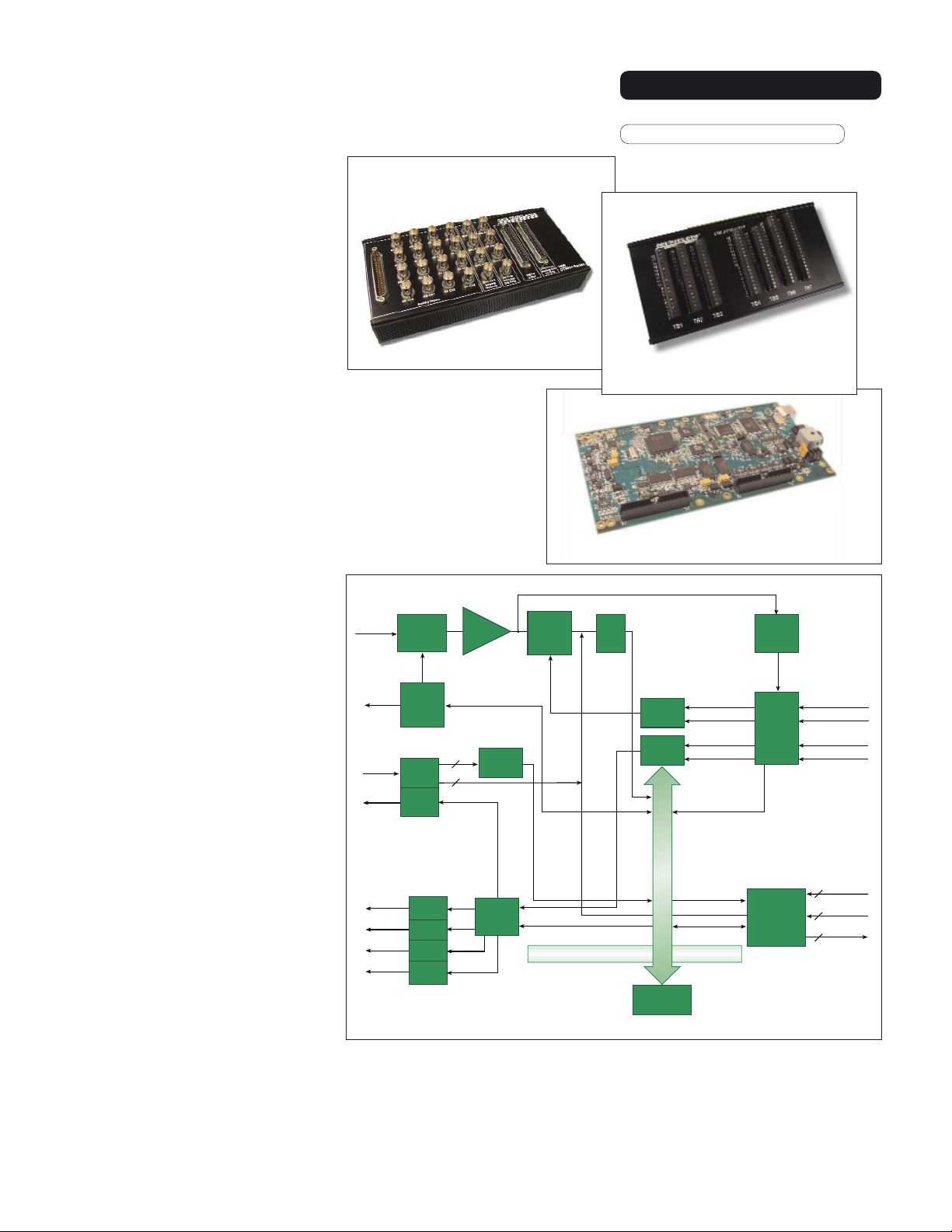
Figure 2. The DT9834 Series provides USB 2.0 multifunction modules for simultaneous
A/D, D/A, DIO, and C/T subsystem operation. This detailed block diagram shows the relationship of each subsystem and the control signals used in the series. For flexible, costeffective solutions, you can choose the number of analog I/O channels and the
the packaging configuration that suits your application.
Type: High-Performance Multifunction
DT9834
BUS: USB
Figure 1.
DT9834 Series
modules are available in
three configurations: BNC or
STP connection box and
OEM embedded version.
(STP connection box available for the 32-analog input
channel version only.)
BNC Connection Box
OEM Embedded
Version
STP
Connection Box
Up to
32SE/16DI
Analog
Input
Dynamic
Digital
Output
4 Analog
Output
Channels
16: 1
Multiplexer
Channel
Gain
List
(1024)
Digital I/O
16 In
16 Out
16-Bit
D/A
16-Bit
D/A
16-Bit
D/A
16-Bit
D/A
Programmable
Gain
1, 2, 4, 8
8
16
Interrupt
Logic
Output
FIFO
16-Bit
A/D
Converter
500 Volt Isolation Barrier
Input
FIFO
Input
Control
Output
Control
USB 2.0
Interface
Ext. A/D Trigger
Ext. A/D Clock
Ext. D/A Trigger
Ext. D/A Clock
Analog
Threshold
Trigger
Clock
and
Trigger
Logic
5 32-Bit
User
Counter/
Tim ers
Ext. A/D Digital
Trigger
Ext. A/D Clock
Ext. D/A Digital
Trigger
Ext. D/A Clock
Clock In
5
Gate
5
Control In
Signal
Output
5
Page 2
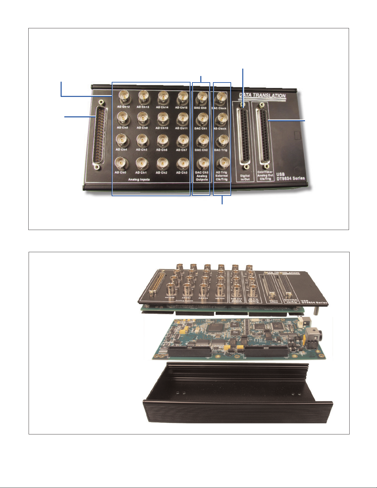
Figure 3. The BNC connection box is available for easy signal connections.
Figure 4. The BNC connection box packages the OEM embedded version of the DT9834 Series in a
CE-compliant enclosure.
Analog Input BNC
Connections
16 single-ended or
8 differential BNCs
Analog Output BNC
Connections
4 analog output BNCs
External Clock & Trigger BNC Connections
External A/D clock and trigger BNCs and external D/A
clock and trigger BNCs
Analog Input
D-Sub
Connector
Access all of the
analog input
signals
Digital I/O D-Sub Connector
Access all of the digital I/O signals
Analog
Output &
Counter/
Timer D-Sub
Connector
Access all of
the analog output and
counter/timer
signals
Easy BNC Connections
BNC Connection Box
Faceplate of BNC
Connection Box
Easy signal connections
OEM Embedded Version
DT9834 Series board
CE-Compliant Enclosure
Maintains signal integrity
BNC Box Assembly
Includes OEM Version
2Data Translation, Inc. US and Canada (800) 525-8528, (508) 481-3700 UK 1256 3333 30 Germany (07142) 95 31-0 Internet www.datatranslation.com
Page 3
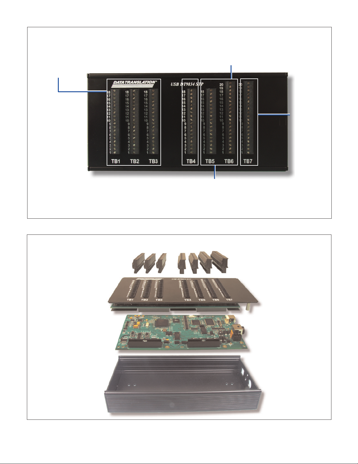
Figure 5. The STP connection box is available for easy signal connections on the 32-channel version of the module.
Figure 6. The STP connection box packages the OEM embedded version of the DT9834 Series in a
CE-compliant enclosure with screw terminal connections.
Analog Input Connections
Access 32 single-ended or
16 differential analog inputs
through screw terminals.
External Clock & Trigger Connections
Access the external A/D clock and trigger signals through
screw terminals.
Counter/
Timer
Connections
Access all of the
counter/timer
signals through
screw terminals.
Easy Screw Terminal Connections
STP Connection Box
Faceplate of STP
Connection Box
Easy signal connections
OEM Embedded Version
DT9834 Series board
CE-Compliant Enclosure
Maintains signal integrity
STP Box Assembly
Includes OEM Version
Digital I/O Connections
Access all of the digital I/O signals through
screw terminals.
STP Connection Box available for the 32-analog input channel version only.
Pluggable Screw Terminals
Easy wiring
Page 4
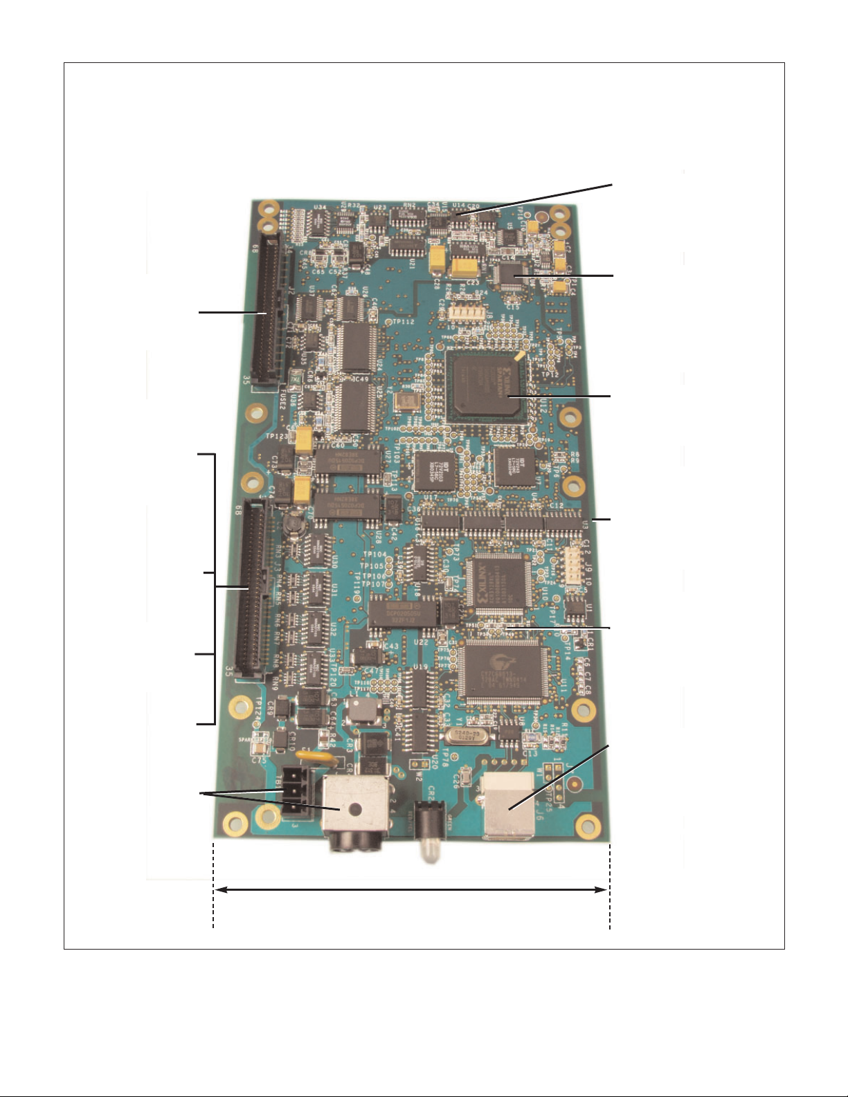
Figure 7. Screw terminal panels are available for the OEM embedded version.
Uncompromised, High-Integrity Performance
OEM Embedded Version
Precision
Measurements...
True 16-bit resolution
at 500 kHz throughput
for measuring
dynamic signals
High Throughput ...
Two-stage instrumentation
amplifiers in series maintain
high-speed throughput
No Limits ...
Full simultaneous operation
of all subsystems
Fully Protected ...
500 V galvanic isolation
protects your computer
and maintains
signal integrity
Designed for Low
Noise ...
12-layer PCB provides
optimal grounding and
shielding to maintain signal
integrity
High-Speed
USB 2.0 ...
USB 2.0 connector for data
transfer at up to 480 Mbps
Flexible Power
Connections ...
+5 V connector; a
secondary +5 V
connector is
provided for
embedded
applications
Clean Signal
Connection ...
Up to 32 high-speed
analog input channels
Ultra Digital I/O ...
Full digital I/O flexibility
for time stamping,
pattern recognition,
and synchronizing with
external events
Full-Featured
Counter/Timers ...
Five 32-bit counter/timers
ideal for automotive
testing applications
Pure Signal
Generation ...
Four waveform,
deglitched DACs
External Control ...
Flexible clocks
and triggers
Euro Card
Compliance ...
100 mm size
4Data Translation, Inc. US and Canada (800) 525-8528, (508) 481-3700 UK 1256 3333 30 Germany (07142) 95 31-0 Internet www.datatranslation.com
Page 5

Overview
The DT9834 Series combines the functionality of multiple boards in a single
USB 2.0 module to provide simultaneous
analog input, analog output, digital I/O,
and counter/timer operations. Available
in a number of configurations, the
DT9834 Series provides maximum flexibility - select the number of analog I/O
channels and the analog I/O resolution
you need, as well as the packaging configuration for your application. All modules feature 16 digital input lines, 16 digital output lines, and 5 counter/timer
channels.
High-Speed, High-Resolution
Analog Inputs
DT9834 Series modules are available in
three analog input channel configurations: 32 single-ended/16 differential, 16
single-ended/8 differential, or no analog
inputs. All analog input signals are multiplexed to a single analog-to-digital converter. All modules feature sampling
rates up to 500 kSamples/s and 16-bit
resolution on both the analog in and analog out.
Four programmable gains (1, 2, 4, and
8) are provided to support input signal
ranges of +/- 10 V, +/-5 V, +/-2.5 V, and
+/-1.25 V. By configuring each analog
input channel for the input range that
you want, you can connect many output
transducers directly to the module.
Flexible Acquisition Modes
Using the DT9834 Series, you can
acquire a single sample from a single
analog input channel or multiple samples from multiple analog input channels. A 1024-location channel-gain list
gives you the flexibility to sample non-
sequential analog input channels, analog input channels with different gains,
and digital inputs and counter/timer
channels with the analog input channels you want at the A/D sample rate.
DT9834 Series modules provide two
ways to cycle through the channel-gain
list:
■
Continuous scan mode – Choose this
mode if you want to accurately control
the period between conversions of individual channels in the channel-gain
list.
■
Triggered scan mode – Choose this
mode if you want to accurately control
both the period between conversions of
individual channels in the channel-gain
list and the period between each scan.
This mode emulates a sample-and-hold
function and is useful when synchronizing or controlling external equipment, or when acquiring a buffer of data
on each trigger. Using this mode, you
can acquire up to 262,144 samples per
trigger (256 times per trigger x 1024location channel-gain list).
High-Speed, High-Resolution
Analog Outputs
DT9834 Series modules are available in
two analog output channel configurations: 4 deglitched analog output channels, or no analog output channels.
Each analog output channel has its
own digital-to-analog converter and
provides an output signal range of +/10 V with a resoluton of 16-bits. You
can achieve a maximum update rate of
500 kSamples/second.
You can update the analog output
channels as you are acquiring analog
input data for gap-free simultaneous
stimulus and response. In addition,
you can update the digital output lines
with the analog output channels at the
analog output rate.
Flexible Output Modes
Using the DT9834 Series, you can output
a single value from a single analog output channel or multiple values from multiple analog output channels. An outputchannel list gives you the flexibility of
updating only the analog output channels you want or updating the digital
output lines with specified analog output
channels at the D/A clock rate. You can
update analog output channels at up to
500 kSamples/s.
The DT9834 features the following
output modes:
■
Continuous output mode – Choose this
mode if you want to accurately control
the period between conversions of individual output channels in the outputchannel list.
■
Waveform mode – Use this mode if you
want to output waveforms repetitively
from an output FIFO on the module,
minimizing communication overhead
with the host computer. If you specify
only one channel in the output-channel
list, you can load a waveform containing up to 128 kSamples into the output
FIFO. If you specify all the analog output channels and the digital output
lines in the output-channel list, you can
load a waveform containing up to 24
kSamples into the output FIFO. Using
waveform mode, you can update multiple channels at up to 500 kSamples/s.
Board Analog In Analog Out Resolution Input Ranges* Throughput Digital In Digital Out Counters Packaging
DT9834-16-0-16-BNC 16SE — 16 PGH 500 kS/s 16 16 5 BNC Box
DT9834-08-0-16-BNC 8DI — 16 PGH 500 kS/s 16 16 5 BNC Box
DT9834-16-0-16-OEM 16SE/8DI — 16 PGH 500 kS/s 16 16 5 OEM Embedded Version
DT9834-16-4-16-BNC 16SE 4 16 PGH 500 kS/s 16 16 5 BNC Box
DT9834-08-4-16-BNC 8DI 4 16 PGH 500 kS/s 16 16 5 BNC Box
DT9834-16-4-16-OEM 16SE/8DI 4 16 PGH 500 kS/s 16 16 5 OEM Embedded Version
DT9834-00-4-16-BNC — 4 16 — 500 kS/s 16 16 5 BNC Box
DT9834-00-4-16-OEM — 4 16 — 500 kS/s 16 16 5 OEM Embedded Version
DT9834-32-0-16-STP 32SE/16DI — 16 PGH 500 kS/s 16 16 5 STP Box
DT9834-32-0-16-OEM 32SE/16DI — 16 PGH 500 kS/s 16 16 5 OEM Embedded Version
*PGH input range = +/– 10, 5, 2.5,1.25 Volts.
High-Performance Data Acquisition USB Modules Matrix
Page 6

High-Speed Digital I/O Lines
DT9834 Series modules feature 16 digital input lines and 16 digital output
lines. The first eight digital input lines
can also be used for interrupt on
change. You can read all the digital
input lines simultaneously with the
analog input channels at the A/D clock
rate. The digital input lines can also be
clocked separately as the only channel
in the channel-gain list at up to 500
kSamples/second.
For digital output operations, you
can update all the digital output lines
with the analog output channels at the
D/A rate. A dynamic digital output line
is also provided for synchronizing
external devices. You can program this
line to change state as an analog input
channel is read.
Flexible Clocks and Triggers
For maximum flexibility, all DT9834
Series modules provide independent
clocks and triggers for the A/D and D/A
subsystems. This allows you to trigger
and clock the analog output subsystem
synchronously with, or independent of,
the analog input subsystem. Each subsystem supports an internal clock and
external clock input, as well as the following trigger types: software command, analog threshold, and external
digital input trigger.
Multifunction Counter/Timers
All DT9834 Series modules feature
five 32-bit user counter/timers. If you
wish, you can read the value of the
counter/timer channels with the analog input channels and digital input
lines at the A/D clock rate. The following counter/timer functions are
supported: event counting, frequency
measurement, pulse width measurement, period measurement, continuous pulse output, one-shot, repetitive
one-shot, and up/down counting
operations.
Programmable gates, edges, clocks,
and output signals are also supported.
Flexible Packaging Configurations
DT9834 Series modules are available in
three packaging configurations: a BNC
or STP connection box and an OEM
embedded version. The BNC connection box is available for 16 singleended channels, 8 differential channels, or 0 analog input channels. The
BNC configurations are enclosed in
metal boxes with standard BNC and Dsub connectors, 4 BNCs for connecting
analog outputs, and 4 BNCs for con-
necting external clocks and triggers.
The STP connection box is available
for 32 single-ended channels or 16 differential analog input channels. The
STP configuration is enclosed in a
metal box with screw terminals for
connecting analog inputs, analog outputs, and external clocks and triggers.
The BNC and STP configurations ship
with a +5 V galvanically isolated power
supply and power cable (EP361), USB
2.0 cable, and Data Acquisition OMNI
CD.
The OEM configuration, ideal for
embedding in test systems, provides all
the functionality of the DT9834 Series
in PC-board form. This configuration
ships with a USB 2.0 cable and Data
Acquisition OMNI CD.
Power
The BNC and STP connection boxes
include a +5 V power supply and power
cable for quick setup. OEMs can purchase these options separately as EP361
(see Figure 10). A secondary power connector is also provided for OEMs to
allow custom power wiring (see Figure
11).
USB 2.0 Compatibility
The DT9834 Series is fully compatible
with USB 2.0 and USB 1.1. USB 2.0
extends the speed of connection to up
to 480 Mbps. For optimal performance,
it is recommended that you use the
DT9834 Series with a USB 2.0 port.
The DT9834 Series can be used with a
USB 1.1 port, but at USB 1.1 performance.
Figure 10. EP361 includes a galvanically
isolated power supply of +5 V and a power
cable. It is included with the BNC configurations of the DT9834 Series.
Figure 11 For OEMs, DT9834 Series modules include a secondary power connector
for custom wiring.
Secondary power
connector
Figure 8. With the optional DIN rail mounting kit (BNC-DIN-RAIL-KIT), you can mount
the DT9834 BNC model to a standard
DIN rail.
Figure 9. Programmable edges allow you to use counter/timers to measure the pulse
width, frequency, and period of a signal.
6Data Translation, Inc. US and Canada (800) 525-8528, (508) 481-3700 UK 1256 3333 30 Germany (07142) 95 31-0 Internet www.datatranslation.com
Connect Signal to
C/T Gate 0
or C/T Clock In 0
Program the
edge to start
the measurement
(rising shown here)
The interval is calculated and
the count is returned.
Pulse width = # of counts
Frequency = 18 MHz
Program the
edge to stop
the measurement
(falling shown here)
18 MHz
# of counts
Period = 1
Frequency
Page 7

500 V Galvanic Isolation Protects
Your Data
Computers are susceptible to groundspikes through any external port. These
spikes can cause system crashes and may
even cause permanent damage to your
computer. DT9834 Series modules feature
500 Volts of galvanic isolation to protect
your computer from ground-spikes and to
ensure a reliable stream of data.
Software
The DT9834 Series ships with the Data
Acquisition OMNI CD, which includes
DT-Open Layers device drivers for
Windows 2000/XP, Ready-to-Measure
applications (called Scope and Quick
Data Acq) that allow you to take data
immediately upon setup, and an evaluation version of our test and measurement
builder, DT Measure Foundry. For maximum flexibility, the DT9834 Series operates under all prominent software applications, including LabVIEW, Visual
Basic, and more. These software choices
allow users of all levels – from programmers to application users – the ability to
access the functionality of the DT9834
Series modules.
Cross-Series Compatibility Saves
Programming Time, Protects Your
Investment
Virtually all Data Translation data acquisition boards, including the DT9834
Series, are compatible with the DT-Open
Layers software standard. This means
that if your application was developed
with one of Data Translation’s software
products, you can easily upgrade to a
new Data Translation board. Little or no
reprogramming is needed. For example,
if you are currently using a DT3016
board on a PCI bus, upgrading to a
DT9834 Series module on the USB bus
is simple – just load and configure the
new driver and you’re done.
Figure 12. DT Measure Foundry allows you to create instrument-like interface applications. This MF Scope example
program, included with DT Measure Foundry, is just one of
the many types of applications that you can create.
Figure 13. Scope is a Ready-To-Measure application for
measuring data immediately upon setup. A dual display
allows you to view live data and real-time FFT data on
one screen. Multiple functions, such as the display mode,
channel display, trigger settings, are all accessible
through one graphical user interface.
Figure 14. DT-LV Link™ allows you to use Data
Tr anslation hardware with LabVIEW.
Figure 15. DTx-EZ allows you to program Data
Tr anslation hardware using Microsoft Visual Basic and
C++.
Page 8

Accessories for OEM Configurations
For applications where you want to embed a DT9834 Series module inside other equipment, use the OEM packaging configuration
(no enclosure) with the following optional accessories:
■ EP361 – A +5 V power supply. It is included with the BNC connection box. (See Figure 10.)
■ EP353 – This accessory panel plugs into connector J2 of a DT9834 Series module and provides one 37-pin, D-sub connector for
attaching analog input signals and one 26-pin connector for attaching a 5B signal conditioning backplane. (See Figure 16.)
■ EP355 – This screw terminal panel plugs into connector J2 or J3 of a DT9834 Series module and provides 14-position screw terminal blocks for attaching analog input, or analog output, digital I/O, counter/timer, and clock and trigger signals.
(See Figure 17.)
■ EP356 – This accessory panel plugs into connector J3 of a DT9834 Series module and provides two 37-pin, D-sub connectors.
You can use one of these connectors to attach analog output, counter/timer, trigger, and clock signals, and the other connector to
attach digital I/O signals. (See Figure 16.)
■ EP333 – This cable connects the STP37 screw terminal panel to a 37-pin female connector on the EP356 or BNC box.
■ EP360 – This cable connects the STP37 screw terminal panel to a 37-pin male (Analog Input) connector on the EP353 or
BNC box.
■ STP37 – This screw terminal panel allows you to connect analog input, digital I/O, analog output, counter/timer, and
clock/trigger signals from the EP353 or EP356 screw terminal panel, or BNC box.
Figure 16. This example shows an EP353 accessory panel,
which plugs into connector J2, and an EP356 accessory panel,
which plugs into connector J3. Use the EP353 to attach analog input signals and a 5B signal conditioning backplane. Use
the EP356 to attach analog output, counter/timer, trigger, and
clock, or digital I/O signals.
Figure 17. The EP355 screw terminal panel plugs into the J2
or J3 connector of a DT9834 Series module. You can attach
analog input, or analog output, counter/timer, trigger, clock,
and digital I/O signals to the screw terminal blocks.
EP353
EP356
EP355
EP355
DT9834 User Manuals
The DT9834 Series includes a getting
started manual and user’s manual.
Manuals are provided in electronic
(PDF) format on the Data Acquisition
OMNI CD provided with the module.
You can also purchase hard copies.
Technical Support
As you develop your application,
application engineers are available during normal business hours to discuss
your requirements. Extensive information, including drivers, example code,
pinouts, a searchable Knowledgebase,
and much more, is available 24 hours a
day on our web site at
www.datatranslation.com. Support is
also available from your point of purchase. Telephone support is free for the
first 90 days; you can also request complimentary support via email or fax at
any time.
Accessories for OEM Embedded Versions
J2
J3
J2
J3
To 5B Signal Conditioning Backplane
To A nalog
Input
Signals
To Digital I/O Signals
To A nalog
Output,
Counter/
Tim er,
Clock/
Tri gger
Signals
To A nalog
Input
Signals
To A nalog
Output,
Counter/
Timer, Clock/
Trigger,
Digital I/O
Signals
8Data Translation, Inc. US and Canada (800) 525-8528, (508) 481-3700 UK 1256 3333 30 Germany (07142) 95 31-0 Internet www.datatranslation.com
Page 9

DT9834 Series Hardware Specifications (Typical at +250C and Rated Voltage, Unless Otherwise Specified)
Analog Inputs
Number of inputs Up to 32 SE/16 DI
Resolution 16-bits 16 bits
Programmable Gain 1,2,4,8
Range +/-10, 5, 2.5, 1.25 V
A/D Throughput
Single channel 500 kS/s
Multiple channel 500 kS/s (aggregate) +/- 0.05%
A/D conversion time 2 µs
Channel acquisition time, +-1/2 LSB 1 µs typical
Sample and Hold Aperture Uncertainty .2 ns typical
Sample and Hold Aperture Delay 50 ns typical
System Accuracy (% of FSR) 500 kHz 400 kHz 250 kHz
Gain=1 +/-0.05% +/-0.03% +/-0.01%
Gain=2 +/-0.06% +/-0.04% +/-0.02%
Gain=4 +/-0.07% +/-0.05% +/-0.02%
Gain=8 +/-0.09% +/-0.07% +/-0.03%
Bipolar Input Range +/-10 V
Output Coding Offset Binary
Common Mode Input Voltage, Max +/-11 V
Common Mode Rejection Ratio, Gain=1 @1 kOhm 80 dB
Maximum Input Voltage without Damage
Power On +/- 30 V
Power Off +/-20 V
Input Impedance
Off Channel 100 MΩ,10 pf
On Channel 100 MΩ,100 pf
Bias Current +/-20 nA
Nonlinearity <1/2 LSB
Differential Nonlinearity 1/2 LSB
Inherent Quantizing Error 1/2 LSB
A/D Zero Drift(/ ° C) +/-10 µV
Gain Drift (of FSR/ ° C) +/-30 ppm
Differential Linearity Drift (of
FSR/
FSR/ ° C) +/-20 ppm
Monotonicity 1 LSB 1 LSB
Analog Outputs
Number of DACs 4
Resolution 16-bits 16 bits
Settling Time to 0.01% of FSR
10 V Step 5 µs 5 µs
100 mV Step 2 µs 2 µs
Throughput 500 kS/s
Slew Rate 10 V/µs
Glitch Energy 12 nV-s typical
Output Range +/-10 V
Data Coding
Bipolar Offset Binary
Output Current +/-5 mA
Output Impedance 0.1 Ω
Capacitive Driver Capability 0.004 µF
Protection Against Short Circuit to analog ground
Nonlinearity 1 LSB 1 LSB
Differential Nonlinearity 1 LSB LSB
Inherent Quantizing Error 1 LSBLSB
Gain Error Adjustable to Zero
Zero Error Adjustable to Zero
Gain Drift +/-30 ppm of FSR/ ° C
Zero Drift (Bipolar) +/-10 ppm of FSR/ ° C
Monotonicity 1 LSB 1 LSB
Page 10

DT9834 Series Hardware Specifications (Typical at +250C and Rated Voltage, Unless Otherwise Specified) -
continued.
Digital I/O Subsystem (All models)
Number of DIO 32 (16 in/16 out), 1 dynamic digital output
Number of Ports 2, 16-bit
Logic Family LVTTL
Logic Sense Positive true
Input Type Level sensitive
Input Termination Inputs tied to +3.3 V with 15 kΩ pullup resistors
Input Logic Load 1 LVTTL load
Logic High Input Voltage 2.0 V minimum
Logic Low Input Voltage 0.8 V maximum
Logic Low Input Current -0.4 mA maximum
Fan-out 12 mA
Logic High Output Voltage 2.0 V minimum
Logic Low Output Voltage 0.8 V maximum
Logic High Output Current -12 mA maximum
Logic Low Output Current 12 mA maximum
Interrupt on Change Yes
Clocked with the sample clock Yes
Software I/O Selectable No
Counter Timer* (All models)
Channels 5
Resolution 32 bits/channel
External A/D and D/A Triggers (All Models)
Triggering Sources:
Internal Software initiated
External Software selectable
Input Type Edge sensitive
Logic Family LVTTL
Logic Load 1 LVTTL load
Input Termination 2.2 kΩ pullup to +3.3 V
Logic Low Input Voltage 0.8 V maximum
Logic High Input Current 25 µA maximum
Logic Low input Current -0.25 mA maximum
Minimum Pulse Width
Clock High 25 ns
Clock Low 25 ns
Triggering Modes:
Single Scan Yes
Continuous Scan Yes
Triggered Scan Yes
Onboard A/D Clocks
Base Frequency 18 MHz
Divisor Range 3 to 4, 294, 967, 295
Usable Range 500 kHz to 0.00419 Hz
Onboard D/A Clocks
Base Frequency 18 MHz
Divisor Range 3 to 4, 294, 967, 295
Usable Range 500 kHz to 0.00419 Hz
* Has same logic high and low voltage and current specifications as the digital I/O lines.
10 Data Translation, Inc. US and Canada (800) 525-8528, (508) 481-3700 UK 1256 3333 30 Germany (07142) 95 31-0 Internet www.datatranslation.com
Page 11

DT9834 Series Hardware Specifications (Typical at +250C and rated Voltage, Unless Otherwise Specified)-
continued.
OEM Embedded Version - Connector J2* Pin Assignments
Pin Signal Pin Signal Pin Signal Pin Signal
1 +5 V Analog 18 Analog Input 8/Analog Input 16a35 Digital Ground 52 Analog In 8 Return/Analog In 24
a
2 Amplifier Low 19 Analog Ground 36 Analog Ground 53 Analog Ground
3 Analog Ground 20 Analog In 7 37 Analog Ground 54 Analog In 7 Return/Analog In 15
b
4 Analog Input 15/Analog Input 23a21 Analog Ground 38 Analog In 15 Return/Analog In 31a55 Analog Ground
5 Analog Ground 22 Analog In 6 39 Analog Ground 56 Analog In 6 Return/Analog In 14
b
6 Analog Input 14/Analog Input 22a23 Analog Ground 40 Analog In 14 Return/Analog In 30ç57 Analog Ground
7 Analog Ground 24 Analog In 5 41 Analog Ground 58 Analog In 5 Return/Analog In 13
b
8 Analog Input 13/Analog Input 21a25 Analog Ground 42 Analog In 13 Return/Analog In 29a59 Analog Ground
9 Analog Ground 26 Analog In 4 43 Analog Ground 60 Analog In 4 Return/Analog In 12
b
10 Analog Input 12/Analog Input 20a27 Analog Ground 44 Analog In 12 Return/Analog In 28a61 Analog Ground
11 Analog Ground 28 Analog In 3 45 Analog Ground 62 Analog In 3 Return/Analog In 11
b
12 Analog Input 11/Analog Input 19a29 Analog Ground 46 Analog In 11 Return/Analog In 27a63 Analog Ground
13 Analog Ground 30 Analog In 2 47 Analog Ground 64 Analog In 2 Return/Analog In 10
b
14 Analog Input 10/Analog Input 18a31 Analog Ground 48 Analog In 10 Return/Analog In 26a65 Analog Ground
15 Analog Ground 32 Analog In 1 49 Analog Ground 66 Analog In 1 Return/Analog In 9
b
16 Analog Input 9/Analog Input 17a33 Analog Ground 50 Analog In 9 Return/Analog In 25a67 Analog Ground
17 Analog Ground 34 Analog In 0 51 Analog Ground 68 Analog In 0 Return/Analog In 8
b
a. These pin assigments apply to the DT9834-32-0-16-OEM and DT9834-32-0-16-STP modules only. The first signal description applies to the differential configuration; the second signal description applies to the
single-ended configuration.
b. The first signal description applies to the differential configuration for all modules. The second signal description applies to the single-ended configuration for the DT9834-16-0-12-OEM, DT9834-08-0-12-OEM,
DT9834-16-0-16-OEM, DT9834-08-0-16-OEM, DT9834-16-4-12-OEM, and DT9834-08-4-12-OEM modules only.
* Mating Connector: Amp 1-104068-8
External A/D and D/A Clocks
Input Type Edge sensitive, rising-edge or falling-edge programmable
Logic Family LVTTL
Logic Load 1 LVTTL load
Input Termination 2.2 kΩ pullup to +3.3 V
Logic High Input Voltage 2.0 V
Logic Low Input Voltage 0.8 V
Logic Low Input Current 1.2 mA
Oscillator Frequency DC to 500 kHz maximum
Minimum Pulse Width
Clock High 25 ns
Clock Low 25 ns
Interface Characteristics
Compatible Bus USB 2.0 or 1.1
Interface Type Bulk
Windows DT-Open Layers Drivers
Plug ‘N Play USB Windows
OEM Board I/O Connectors 2, 68-pin connectors
Fully packaged Enclosure with BNC and D-Sub connectors, or board-only
Power Requirements
+5 Volts +/-5%, @ 2 A Maximum
Physical /Environmental
Dimensions (OEM Embedded Version) 190 mm x 100 mm
Dimensions (BNC Box Version) 215.9 mm (L) x 105.9 mm (W) x 50 mm (H)
Dimensions (STP Box Version) 216 mm (L) x 106 mm (W) x 51 mm (H)
Weight (OEM Embedded Version) 4.6 oz.
Weight (STP Embedded Version) 2.1 lbs.
Operating Temperature Range -0 to +55 ° C
Storage Temperature Range -25 to 85 ° C
Relative Humidity to 95% non-condensing
Page 12

Pin Signal Pin Signal
1 Counter 4 Out 35 Counter 4 Gate
2Counter 4 Clock 36 Digital Ground
3 Counter 3 Out 37 Counter 3 Gate
4Counter 3 Clock 38 Digital Ground
5 Counter 2 Out 39 Counter 2 Gate
6Counter 2 Clock 40 Digital Ground
7 Counter 1 Out 41 Counter 1 Gate
8Counter 1 Clock 42 Digital Ground
9 Counter 0 Out 43 Counter 0 Gate
10 Counter 0 Clock 44 Digital Ground
11 Digital Ground 45 Dynamic Digital Out
12 Digital Input 15 46 Digital Out 15
13 Digital Input 14 47 Digital Out 14
14 Digital Input 13 48 Digital Out 13
15 Digital Input 12 49 Digital Out 12
16 Digital Input 11 50 Digital Out 11
17 Digital Input 10 51 Digital Out 10
18 Digital Input 9 52 Digital Out 9
19 Digital Input 8 53 Digital Out 8
20 Digital Input 7 54 Digital Out 7
21 Digital Input 6 55 Digital Out 6
22 Digital Input 5 56 Digital Out 5
23 Digital Input 4 57 Digital Out 4
24 Digital Input 3 58 Digital Out 3
25 Digital Input 2 59 Digital Out 2
26 Digital Input 1 60 Digital Out 1
27 Digital Input 0 61 Digital Out 0
28 External ADC Clock 62 External ADC Trigger
29 External DAC Clock 63 External DAC Trigger
30 Digital Ground 64 Digital Ground
31 Analog Out 3 65 Analog Out 3 Return
32 Analog Out 2 66 Analog Out 2 Return
33 Analog Out 1 67 Analog Out 1 Return
34 Analog Out 0 68 Analog Out 0 Return
OEM Embedded Version - Connector J3* Pin Assignments
* Mating Connector: Amp 1-104068-8
12 Data Translation, Inc. US and Canada (800) 525-8528, (508) 481-3700 UK 1256 3333 30 Germany (07142) 95 31-0 Internet www.datatranslation.com
Page 13

Accessories (Sold Separately)
■ EP361 — A +5 V power supply (included with BNC configurations).
■ EP353 — Accessory panel for attaching analog input
signals and 5B signal conditioning backplanes (for OEM
configurations only).
■ EP355 — Screw terminal panel for attaching analog I/O
and digital I/O signals (for OEM configurations only).
■ EP356 — Accessory panel for attaching analog output,
counter/timer, trigger, clock signals, and digital I/O
signals (for OEM configurations only).
■ 5B01 — A 16-channel 5B Series backplane used with
the EP353 and AC1315.
■ 5B08 — An 8-channel 5B Series backplane used with the
EP353 and AC1315.
■ AC1315 — Cable that connects to a 5B01 or 5B08.
■ EP333 — Cable between STP37 and EP356 or BNC box.
■ EP360 — Cable between STP37 and EP353 or BNC box.
■ STP37 — Screw terminal panel for EP356, EP353, or
BNC box.
■ BNC-DIN-RAIL-KIT — DIN rail mounting kit.
Software
The following products include a copy of the software,
a single-user license, and a user manual. All software
is supplied on CD-ROM, except as noted.
■
DT Measure Foundry test and measurement application
builder for Windows 2000/XP
SPI300-CD
Free Software Downloads
Data Translation now offers free downloads on the Web for:
■ DT-LV Link to access the power of our boards through
LabVIEW.
■ DTx-EZ to access visual programming tools for
Microsoft Visual Basic and Visual C++.
■ DAQ Adaptor for MATLAB to access the analysis and
visualization tools in MATLAB.
.
Ordering Guide:
Ordering Summary
Type: High-Performance Multifunction
DT9834
BUS: USB
Module Ordering Summary
©
Copyright 2006 Data Translation, Inc. All rights reserved.
All trademarks are the property of their respective holders.
Prices, availability, and specifications subject to change without
notice.
Board Analog In Analog Out Resolution Input Ranges* Throughput Digital In Digital Out Counters Packaging
DT9834-16-0-16-BNC 16SE — 16 PGH 500 kS/s 16 16 5 BNC Box
DT9834-08-0-16-BNC 8DI — 16 PGH 500 kS/s 16 16 5 BNC Box
DT9834-16-0-16-OEM 16SE/8DI — 16 PGH 500 kS/s 16 16 5 OEM Embedded Version
DT9834-16-4-16-BNC 16SE 4 16 PGH 500 kS/s 16 16 5 BNC Box
DT9834-08-4-16-BNC 8DI 4 16 PGH 500 kS/s 16 16 5 BNC Box
DT9834-16-4-16-OEM 16SE/8DI 4 16 PGH 500 kS/s 16 16 5 OEM Embedded Version
DT9834-00-4-16-BNC — 4 16 — 500 kS/s 16 16 5 BNC Box
DT9834-00-4-16-OEM — 4 16 — 500 kS/s 16 16 5 OEM Embedded Version
DT9834-32-0-16-STP 32SE/16DI — 16 PGH 500 kS/s 16 16 5 STP Box
DT9834-32-0-16-OEM 32SE/16DI — 16 PGH 500 kS/s 16 16 5 OEM Embedded Version
*PGH input range = +/– 10, 5, 2.5,1.25 Volts.
All DT9834 Series modules are shipped with a USB cable and the Data Acquisition OMNI CD,
which includes DT-Open Layers-compliant device drivers for Microsoft Windows 2000/XP,
an evaluation version of DT Measure Foundry, Ready-to-Measure software, and comprehensive
manuals in PDF form. The EP361 (power supply) is included with the BNC box configuration.
DT9834
Analog Inputs (4 versions)
00 = 0
08 = 8 differential channels
16 = 16 single-ended channels
or 16 single-ended/
8 differential for the OEM
configuration
32 = 32 single-ended/16 differential
channels
Analog Outputs (2 versions)
0 = 0
4 = 4
PAK = Package Configuration (2 versions)
OEM = Board-level embedded version for maximum flexibility (no power supply).
BNC = A metal box enclosure with either 16 BNCs for single-ended analog inputs,
8 BNCs for differential analog inputs, or 0 BNCs for 0 analog
inputs. If you select a model with analog outputs, 4 BNCs are
provided for connecting analog output signals. The BNC box configuration
provides 4 BNCs for connecting external clocks and triggers.
(EP361 power supply and power cable included.)
STP = A metal box enclosure with screw terminals for connecting 32 single-ended
or 16 differential analog inputs, 16 digital inputs, 16 digital outputs, 5
counter/timers, an external trigger, or an external clock. (EP348 power
supply and power cable included.)
-XX -XX -XXX-X
Throughput/Resolution
16 = 16-bit A/D and D/A resolution at 500 kHz
 Loading...