

Page 1

UM-20769-E
DT9812,
DT9813, and
DT9814
User’s Manual
Page 2

Fifth Edition
March, 2006
Data Translation, Inc.
100 Locke Drive
Marlboro, MA 01752-1192
(508) 481-3700
www.datatranslation.com
Fax: (508) 481-8620
E-mail: info@datx.com
Copyright © 2006 by Data Translation, Inc.
All rights reserved.
Information furnished by Data Translation, Inc.
is believed to be accurate and reliable; however,
no responsibility is assumed by Data Translation,
Inc. for its use; nor for any infringements of
patents or other rights of third parties which
may result from its use. No license is granted by
implication or otherwise under any patent rights
of Data Translation, Inc.
Use, duplication, or disclosure by the United
States Government is subject to restrictions as set
forth in subparagraph (c)(1)(ii) of the Rights in
Technical Data and Computer software clause at
48 C.F.R, 252.227-7013, or in subparagraph (c)(2)
of the Commercial computer Software Registered Rights clause at 48 C.F.R., 52-227-19 as
applicable. Data Translation, Inc., 100 Locke
Drive, Marlboro, MA 01752
Data Translation® is a registered trademark of
Data Translation, Inc. DT-Open Layers
DataAcq SDK
TM
, DT-LV LinkTM, and DTx-EZTM
TM
,
are trademarks of Data Translation, Inc.
All other brand and product names are
trademarks or registered trademarks of their
respective companies.
Page 3

Radio and Television Interference
This equipment has been tested and found to comply with CISPR
EN55022 Class A, and EN50082-1 (CE) requirements and also with
the limits for a Class A digital device, pursuant to Part 15 of the FCC
Rules. These limits are designed to provide reasonable protection
against harmful interference when the equipment is operated in a
commercial environment. This equipment generates, uses, and can
radiate radio frequency energy and, if not installed and used in
accordance with the instruction manual, may cause harmful
interference to radio communications. Operation of this equipment in
a residential area is likely to cause harmful interference, in which case
the user will be required to correct the interference at his own
expense.
Changes or modifications to this equipment not expressly approved
by Data Translation could void your authority to operate the
equipment under Part 15 of the FCC Rules.
Note: This product was verified to meet FCC requirements under
test conditions that included use of shielded cables and connectors
between system components. It is important that you use shielded
cables and connectors to reduce the possibility of causing
interference to radio, television, and other electronic devices.
Canadian Department of Communications Statement
This digital apparatus does not exceed the Class A limits for radio
noise emissions from digital apparatus set out in the Radio
Interference Regulations of the Canadian Department of
Communications.
Le présent appareil numérique n’émet pas de bruits radioélectriques
dépassant les limites applicables aux appareils numériques de la class
A prescrites dans le Règlement sur le brouillage radioélectrique
édicté par le Ministère des Communications du Canada.
Page 4

Page 5

Table of Contents
About this Manual . . . . . . . . . . . . . . . . . . . . . . . . . . . . . . . . . 11
Intended Audience. . . . . . . . . . . . . . . . . . . . . . . . . . . . . . . . . . . . . . 11
How this Manual is Organized . . . . . . . . . . . . . . . . . . . . . . . . . . . 12
Conventions Used in this Manual . . . . . . . . . . . . . . . . . . . . . . . . . 13
Related Information . . . . . . . . . . . . . . . . . . . . . . . . . . . . . . . . . . . . . 13
Where To Get Help. . . . . . . . . . . . . . . . . . . . . . . . . . . . . . . . . . . . . . 14
Chapter 1: Overview . . . . . . . . . . . . . . . . . . . . . . . . . . . . . . . 15
Key Hardware Features . . . . . . . . . . . . . . . . . . . . . . . . . . . . . . . . . 16
Channel-Gain List . . . . . . . . . . . . . . . . . . . . . . . . . . . . . . . . . . . 17
Counter/Timer Channel . . . . . . . . . . . . . . . . . . . . . . . . . . . . . 17
Supported Software . . . . . . . . . . . . . . . . . . . . . . . . . . . . . . . . . . . . . 17
Getting Started Procedure. . . . . . . . . . . . . . . . . . . . . . . . . . . . . . . . 19
Part 1: Getting Started . . . . . . . . . . . . . . . . . . . . 21
Chapter 2: Preparing to Use a Module. . . . . . . . . . . . . . . . . 23
Unpacking . . . . . . . . . . . . . . . . . . . . . . . . . . . . . . . . . . . . . . . . . . . . . 24
Checking the System Requirements . . . . . . . . . . . . . . . . . . . . . . . 25
Installing the Software. . . . . . . . . . . . . . . . . . . . . . . . . . . . . . . . . . . 26
Chapter 3: Setting Up and Installing
the Module . . . . . . . . . . . . . . . . . . . . . . . . . . . . . . . . . . . . . . . 29
Attaching Modules to the Computer . . . . . . . . . . . . . . . . . . . . . . 31
Connecting Directly to the USB Ports . . . . . . . . . . . . . . . . . . 31
Connecting to an Expansion Hub . . . . . . . . . . . . . . . . . . . . . 33
Changing the Name of a Module (Optional) . . . . . . . . . . . . . . . . 35
Chapter 4: Wiring Signals to the Module. . . . . . . . . . . . . . . 37
5
Page 6

Contents
Preparing to Wire Signals . . . . . . . . . . . . . . . . . . . . . . . . . . . . . . . . 39
Wiring Recommendations . . . . . . . . . . . . . . . . . . . . . . . . . . . . 39
Wiring Locations . . . . . . . . . . . . . . . . . . . . . . . . . . . . . . . . . . . . 39
Connecting Analog Input Signals . . . . . . . . . . . . . . . . . . . . . . . . . 43
Connecting Analog Output Signals . . . . . . . . . . . . . . . . . . . . . . . 44
Connecting Digital I/O Signals . . . . . . . . . . . . . . . . . . . . . . . . . . . 45
Connecting Counter/Timer Signals . . . . . . . . . . . . . . . . . . . . . . . 47
Event Counting . . . . . . . . . . . . . . . . . . . . . . . . . . . . . . . . . . . . . 47
Frequency Measurement . . . . . . . . . . . . . . . . . . . . . . . . . . . . . 49
Edge-to-Edge Measurement . . . . . . . . . . . . . . . . . . . . . . . . . . 50
Rate Generation . . . . . . . . . . . . . . . . . . . . . . . . . . . . . . . . . . . . 52
Chapter 5: Verifying the Operation
of a Module. . . . . . . . . . . . . . . . . . . . . . . . . . . . . . . . . . . . . . . 53
Overview . . . . . . . . . . . . . . . . . . . . . . . . . . . . . . . . . . . . . . . . . . . . . 55
Using the Oscilloscope Function . . . . . . . . . . . . . . . . . . . . . . . . . . 57
Using the Chart Recorder Function . . . . . . . . . . . . . . . . . . . . . . . 58
Using the Voltmeter Function . . . . . . . . . . . . . . . . . . . . . . . . . . . . 59
Using the File Viewer Function . . . . . . . . . . . . . . . . . . . . . . . . . . . 60
Using the Waveform Generator Function . . . . . . . . . . . . . . . . . . 61
Using the Digital Input Function . . . . . . . . . . . . . . . . . . . . . . . . . 62
Using the Digital Output Function . . . . . . . . . . . . . . . . . . . . . . . . 63
Using the Counter Function . . . . . . . . . . . . . . . . . . . . . . . . . . . . . . 64
Using the Rate Generator Function . . . . . . . . . . . . . . . . . . . . . . . 65
Part 2: Using Your Module . . . . . . . . . . . . . . . . . 67
Chapter 6: Principles of Operation . . . . . . . . . . . . . . . . . . . 69
Analog Input Features. . . . . . . . . . . . . . . . . . . . . . . . . . . . . . . . . . . 73
Input Resolution . . . . . . . . . . . . . . . . . . . . . . . . . . . . . . . . . . . . 73
Analog Input Channels . . . . . . . . . . . . . . . . . . . . . . . . . . . . . . 73
6
Page 7

Specifying a Single Analog Input Channel . . . . . . . . . 74
Specifying One or More Analog Input Channels . . . . 74
Input Ranges and Gains . . . . . . . . . . . . . . . . . . . . . . . . . . . . . 75
Specifying the Gain for a Single Channel . . . . . . . . . . . 76
Specifying the Gain for One or More Channels . . . . . . 76
Input Sample Clock Sources . . . . . . . . . . . . . . . . . . . . . . . . . . 77
Analog Input Conversion Modes . . . . . . . . . . . . . . . . . . . . . 78
Single-Value Operations . . . . . . . . . . . . . . . . . . . . . . . . . . 78
Continuous Scan Mode . . . . . . . . . . . . . . . . . . . . . . . . . . 78
Input Triggers . . . . . . . . . . . . . . . . . . . . . . . . . . . . . . . . . . . . . . 80
Data Transfer . . . . . . . . . . . . . . . . . . . . . . . . . . . . . . . . . . . . . . . 80
Data Format . . . . . . . . . . . . . . . . . . . . . . . . . . . . . . . . . . . . . . . 81
Converting a Binary Code to a Voltage . . . . . . . . . . . . 81
Converting a Twos Complement Code to a Voltage . . 82
Error Conditions . . . . . . . . . . . . . . . . . . . . . . . . . . . . . . . . . . . . 82
Analog Output Features . . . . . . . . . . . . . . . . . . . . . . . . . . . . . . . . . 83
Output Resolution . . . . . . . . . . . . . . . . . . . . . . . . . . . . . . . . . . 83
Analog Output Channels . . . . . . . . . . . . . . . . . . . . . . . . . . . . 83
Specifying a Single Analog Output Channel . . . . . . . . 83
Specifying Analog Output Channels . . . . . . . . . . . . . . 84
Output Ranges and Gains . . . . . . . . . . . . . . . . . . . . . . . . . . . . 84
Output Trigger . . . . . . . . . . . . . . . . . . . . . . . . . . . . . . . . . . . . . . 85
Output Clock . . . . . . . . . . . . . . . . . . . . . . . . . . . . . . . . . . . . . . . 85
Output Conversion Modes . . . . . . . . . . . . . . . . . . . . . . . . . . . 85
Single-Value Operations . . . . . . . . . . . . . . . . . . . . . . . . . . 86
Continuous Output Mode . . . . . . . . . . . . . . . . . . . . . . . 86
Data Transfer . . . . . . . . . . . . . . . . . . . . . . . . . . . . . . . . . . . . . . . 87
Data Format . . . . . . . . . . . . . . . . . . . . . . . . . . . . . . . . . . . . . . . 88
Converting a Voltage into a Binary Code . . . . . . . . . . . 88
Converting a Voltage to a Twos Complement Code . . 89
Contents
7
Page 8

Contents
Error Conditions . . . . . . . . . . . . . . . . . . . . . . . . . . . . . . . . . . . . 89
Digital I/O Features. . . . . . . . . . . . . . . . . . . . . . . . . . . . . . . . . . . . . 90
Digital I/O Lines . . . . . . . . . . . . . . . . . . . . . . . . . . . . . . . . . . . 90
Resolution . . . . . . . . . . . . . . . . . . . . . . . . . . . . . . . . . . . . . . . . . 90
Operation Modes . . . . . . . . . . . . . . . . . . . . . . . . . . . . . . . . . . . 91
Counter/Timer Features . . . . . . . . . . . . . . . . . . . . . . . . . . . . . . . . . 91
C/T Channels . . . . . . . . . . . . . . . . . . . . . . . . . . . . . . . . . . . . . . 91
C/T Clock Sources . . . . . . . . . . . . . . . . . . . . . . . . . . . . . . . . . . 92
Gate Types . . . . . . . . . . . . . . . . . . . . . . . . . . . . . . . . . . . . . . . . . 93
Pulse Duty Cycles . . . . . . . . . . . . . . . . . . . . . . . . . . . . . . . . . . 93
Counter/Timer Operation Modes . . . . . . . . . . . . . . . . . . . . . 94
Event Counting . . . . . . . . . . . . . . . . . . . . . . . . . . . . . . . . 94
Frequency Measurement . . . . . . . . . . . . . . . . . . . . . . . . . 95
Edge-to-Edge Measurement . . . . . . . . . . . . . . . . . . . . . . 96
Rate Generation . . . . . . . . . . . . . . . . . . . . . . . . . . . . . . . . 97
Chapter 7: Supported Device Driver Capabilities. . . . . . . . 99
Data Flow. . . . . . . . . . . . . . . . . . . . . . . . . . . . . . . . . . . . . . . . . . . . . 101
Buffering . . . . . . . . . . . . . . . . . . . . . . . . . . . . . . . . . . . . . . . . . . . . . 102
DMA. . . . . . . . . . . . . . . . . . . . . . . . . . . . . . . . . . . . . . . . . . . . . . . . . 102
Triggered Scan Mode . . . . . . . . . . . . . . . . . . . . . . . . . . . . . . . . . . . 103
Gain . . . . . . . . . . . . . . . . . . . . . . . . . . . . . . . . . . . . . . . . . . . . . . . . . 104
Synchronous Digital I/O. . . . . . . . . . . . . . . . . . . . . . . . . . . . . . . . 105
Channels . . . . . . . . . . . . . . . . . . . . . . . . . . . . . . . . . . . . . . . . . . . . . 105
Filters . . . . . . . . . . . . . . . . . . . . . . . . . . . . . . . . . . . . . . . . . . . . . . . . 106
Ranges . . . . . . . . . . . . . . . . . . . . . . . . . . . . . . . . . . . . . . . . . . . . . . . 106
Resolution . . . . . . . . . . . . . . . . . . . . . . . . . . . . . . . . . . . . . . . . . . . . 107
Triggers . . . . . . . . . . . . . . . . . . . . . . . . . . . . . . . . . . . . . . . . . . . . . . 108
Clocks. . . . . . . . . . . . . . . . . . . . . . . . . . . . . . . . . . . . . . . . . . . . . . . . 109
Counter/Timers . . . . . . . . . . . . . . . . . . . . . . . . . . . . . . . . . . . . . . . 110
8
Page 9

Miscellaneous . . . . . . . . . . . . . . . . . . . . . . . . . . . . . . . . . . . . . . . . . 112
Chapter 8: Programming Flowcharts. . . . . . . . . . . . . . . . . 113
Single-Value Operations . . . . . . . . . . . . . . . . . . . . . . . . . . . . . . . . 115
Continuous A/D Operations . . . . . . . . . . . . . . . . . . . . . . . . . . . . 117
Continuous D/A Operations . . . . . . . . . . . . . . . . . . . . . . . . . . . . 119
Event Counting Operations . . . . . . . . . . . . . . . . . . . . . . . . . . . . . 121
Frequency Measurement Operations . . . . . . . . . . . . . . . . . . . . . 123
Edge-to-Edge Measurement Operations . . . . . . . . . . . . . . . . . . 125
Pulse Output Operations. . . . . . . . . . . . . . . . . . . . . . . . . . . . . . . . 127
Simultaneous Operations . . . . . . . . . . . . . . . . . . . . . . . . . . . . . . . 129
Chapter 9: Troubleshooting . . . . . . . . . . . . . . . . . . . . . . . . 143
General Checklist . . . . . . . . . . . . . . . . . . . . . . . . . . . . . . . . . . . . . . 144
Technical Support . . . . . . . . . . . . . . . . . . . . . . . . . . . . . . . . . . . . . 148
If Your Module Needs Factory Service . . . . . . . . . . . . . . . . . . . . 149
Chapter 10: Calibration . . . . . . . . . . . . . . . . . . . . . . . . . . . . 151
Using the DT9812 Series Calibration Utility . . . . . . . . . . . . . . . 153
Calibrating the Analog Input Subsystem . . . . . . . . . . . . . . . . . . 154
Connecting a Precision Voltage Source . . . . . . . . . . . . . . . . 154
Using the Auto-Calibration Procedure . . . . . . . . . . . . . . . . 154
Using the Manual Calibration Procedure . . . . . . . . . . . . . . 155
Calibrating the Analog Output Subsystem . . . . . . . . . . . . . . . . 156
Contents
Appendix A: Specifications . . . . . . . . . . . . . . . . . . . . . . . . 157
Appendix B: Screw Terminal Assignments . . . . . . . . . . . 169
Appendix C: Reading from or Writing to the Digital Registers
173
9
Page 10

Contents
10
Page 11

The first part of this manual describes how to install and set up your
DT9812-2.5V, DT9812-10V, DT9813-10V, and DT9814-10V modules
and software, and verify that your modules are working properly.
The second part of this manual describes the features of the
DT9812-2.5V, DT9812-10V, DT9813-10V, and DT9814-10V modules,
the capabilities of the device driver, and how to program the modules
using the DT-Open Layers™ software. It also provides
troubleshooting information.
Note: If the information in this manual applies to both versions of
the DT9812 module, this manual uses the product name "DT9812
module." If the information applies to a specific module, this manual
uses the specific product name.
Intended Audience
About this Manual
This document is intended for engineers, scientists, technicians, or
others responsible for using and/or programming the modules for
data acquisition operations in the Microsoft® Windows® 2000 or
Windows XP operating system. It is assumed that you have some
familiarity with data acquisition principles and that you understand
your application.
11
Page 12

About this Manual
How this Manual is Organized
This manual is organized as follows:
• Chapter 1, “Overview,” describes the major features of the
DT9812-2.5V, DT9812-10V, DT9813-10V, and DT9814-10V
modules, as well as the supported software and accessories for
the modules.
• Chapter 2, “Preparing to Use a Module,” describes how to
unpack the module, check the system requirements, and install
the software.
• Chapter 3, “Setting Up and Installing the Module,” describes
how to install the module and how to configure the device driver.
• Chapter 4, “Wiring Signals to the Module,” describes how to
wire signals to the module.
• Chapter 5, “Verifying the Operation of a Module,” describes
how to verify the operation of the module with the GO!
application.
• Chapter 6, “Principles of Operation,” describes all of the features
of the modules and how to use them in your application.
12
• Chapter 7, “Supported Device Driver Capabilities,” lists the data
acquisition subsystems and the associated features accessible
using the device driver.
• Chapter 8, “Programming Flowcharts,” describes the processes
you must follow to program the subsystems of a module using
DT-Open Layers-compliant software.
• Chapter 9, “Troubleshooting,” provides information that you can
use to resolve problems with a module and device driver, should
they occur.
• Chapter 10, “Calibration,” describes how to calibrate the analog
I/O circuitry of the 10V modules.
• Appendix A, “Specifications,” lists the specifications of the
modules.
Page 13

• Appendix B, “Screw Terminal Assignments,” shows the screw
terminal assignments of the modules.
• Appendix C, “Reading from or Writing to the Digital Registers,”
describes register-level functions that you can use to program the
digital I/O lines of your module.
• An index completes this manual.
Conventions Used in this Manual
The following conventions are used in this manual:
• Notes provide useful information or information that requires
special emphasis, cautions provide information to help you avoid
losing data or damaging your equipment, and warnings provide
information to help you avoid catastrophic damage to yourself or
your equipment.
• Items that you select or type are shown in bold.
About this Manual
Related Information
Refer to the following documents for more information on using the
DT9812, DT9813, and DT9814 modules:
• Benefits of the Universal Serial Bus for Data Acquisition. This white
paper describes why USB is an attractive alternative for data
acquisition. It is available on the Data Translation web site
(www.datatranslation.com).
• DT Measure Foundry Getting Started Manual (UM-19298) and
online help. These documents describe how to use DT Measure
Foundry™ to build drag-and-drop test and measurement
applications for Data Translation® data acquisition devices
without programming.
• DataAcq SDK User’s Manual (UM-18326). For programmers who
are developing their own application programs using the
13
Page 14

About this Manual
Microsoft C compiler, this manual describes how to use the
DT-Open Layers DataAcq SDK™ to access the capabilities of
Data Translation data acquisition devices.
• DTx-EZ Getting Started Manual (UM-15428). This manual
describes how to use the ActiveX controls provided in DTx-EZ™
to access the capabilities of Data Translation data acquisition
devices in Microsoft Visual Basic® or Visual C++®.
• DT-LV Link Getting Started Manual (UM-15790). This manual
describes how to use DT-LV Link™ with the LabVIEW™
graphical programming language to access the capabilities of
Data Translation data acquisition devices.
• DAQ Adaptor for MATLAB (UM-22024). This document describes
how to use Data Translation’s DAQ Adaptor to provide an
interface between the MATLAB Data Acquisition subsystem
from The MathWorks and Data Translation’s DT-Open Layers
architecture.
• Microsoft Windows 2000 or Windows XP documentation.
• USB web site (http://www.usb.org).
14
Where To Get Help
Should you run into problems installing or using a module, the Data
Translation Technical Support Department is available to provide
technical assistance. Refer to Chapter 9 for more information. If you
are outside the United States or Canada, call your local distributor,
whose number is listed on our web site (www.datatranslation.com).
Page 15

1
Overview
Key Hardware Features. . . . . . . . . . . . . . . . . . . . . . . . . . . . . . . . . . 16
Supported Software . . . . . . . . . . . . . . . . . . . . . . . . . . . . . . . . . . . . . 17
Getting Started Procedure. . . . . . . . . . . . . . . . . . . . . . . . . . . . . . . . 19
15
Page 16
Chapter 1
Key Hardware Features
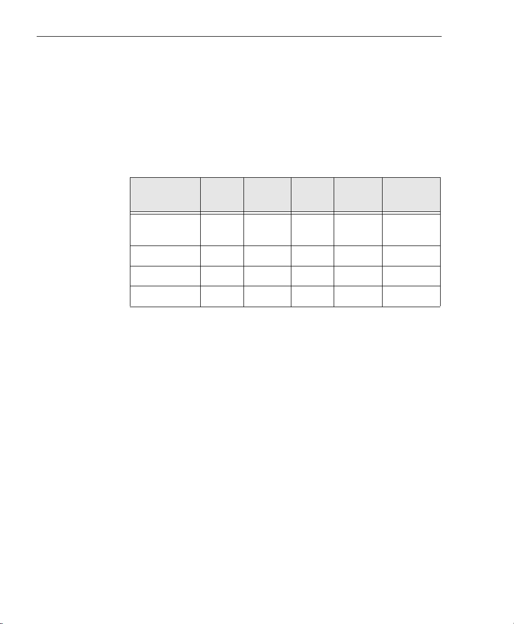
The DT9812-2.5V, DT9812-10V, DT9813-10V, and DT9814-10V
modules are part of the ECONseries of economy, multifunction
mini-instruments. Tabl e 1 lists the key features of each module.
Table 1: Key Features of the DT9812, DT9813, and DT9814
Modules
Analog
Module
DT9812-2.5V 8 SE 2 0 to
DT9812-10V 8 SE 2
DT9813-10V
DT9814-10V
Inputs
16 SE
24 SE
Analog
Outputs
2
2
I/O
Range
2.44 V
±10 V
±10 V
±10 V
Sample
Rate
50 kS/s 8 in/ 8 out
50 kS/s 8 in/ 8 out
50 kS/s 4 in/ 4 out
50 kS/s --
All modules provide the following features:
• 2-location output channel list. You can update both DACs
simultaneously at up to 50 kSamples/s
• 12-bit resolution
• One 32-bit counter/timer channel
• Internal and external A/D clock sources
• Internal and external A/D trigger sources
• No external power supply required
Digital
I/O
16
Page 17

Channel-Gain List
Overview
All modules support a 32-location channel-gain list. You can cycle
through the channel-gain list using continuous scan mode or
triggered scan mode.
Counter/Timer Channel
All modules support one 32-bit counter/timer (C/T) channel that
performs event counting, frequency measurement, edge-to-edge
measurement, and rate generation (continuous pulse output)
operations.
Supported Software
The following software is available for use with the DT9812, DT9813,
and DT9814 modules, and is provided on the ECON CD:
• Device Driver – The DT9812, DT9813, or DT9814 Device Driver
allows you to use these modules with any of the supported
software packages or utilities. Refer to Chapter 2 for more
information on loading the device driver.
• GO! application – The GO! application provides a quick way to
measure and control data from an ECONseries module right out
of the box. The following instrument views make acquiring data
and controlling signals easy: oscilloscope, chart recorder, file
viewer, digital voltmeter, waveform generator, digital input,
digital output, counter, and rate generator. Refer to Chapter 5 for
more information on using this application.
• DataAcq SDK – Use the Data Acq SDK if you want to develop
your own application software for your modules using the
Microsoft C compiler; the DataAcq SDK complies with the
DT-Open Layers standard.
1
1
1
1
1
1
1
1
1
17
Page 18

Chapter 1
• DTx-EZ – Use this optional software package if you want to use
ActiveX controls to access the capabilities of your modules using
Microsoft Visual Basic or Visual C++; DTx-EZ complies with the
DT-Open Layers
standard.
• DAQ Adaptor for MATLAB – Data Translation’s DAQ Adaptor
provides an interface between the MATLAB Data Acquisition
(DAQ) subsystem from The MathWorks and Data Translation’s
DT-Open Layers architecture.
• DT-LV Link – Use this optional software package if you want to
use the LabVIEW graphical programming language to access the
capabilities of your modules.
• DT Measure Foundry – An evaluation version of this software is
included or provided via a link on the ECON CD. DT Measure
Foundry is drag-and-drop test and measurement application
builder designed to give you top performance with ease-of-use
development. Order the full development version of this
software package to develop your own application using real
hardware.
18
Page 19

Getting Started Procedure
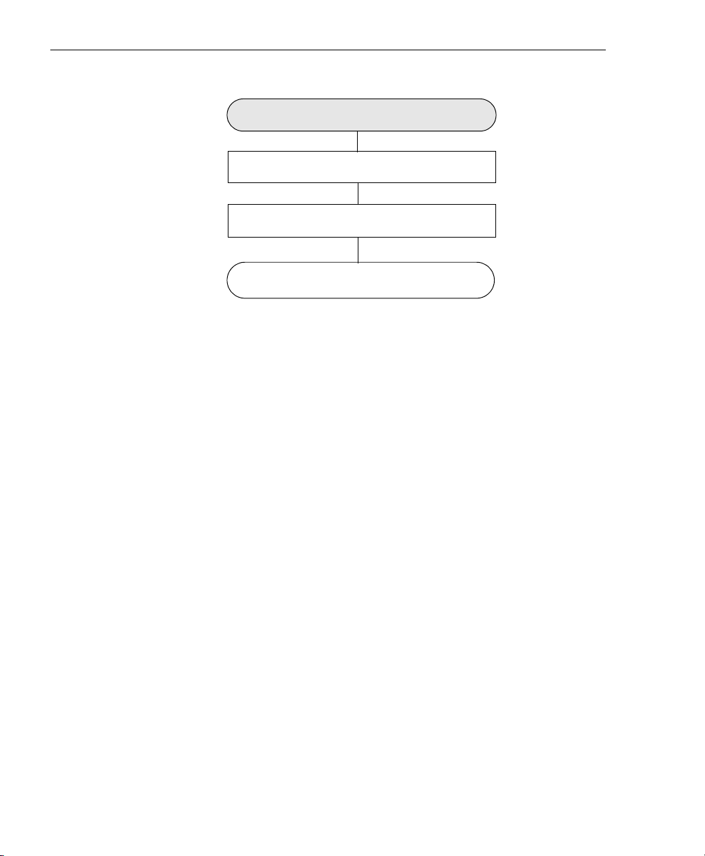
The flow diagram shown in Figure 1 illustrates the steps needed to
get started using the modules. This diagram is repeated in each
chapter; the shaded area in the diagram shows you where you are in
the getting started procedure.
Prepare to Use the Module
(see Chapter 2 starting on page 23)
Set Up and Install the Module
(see Chapter 3 starting on page 29)
Overview
1
1
1
Wire Signals to the Module
(see Chapter 4 starting on page 37)
Verify the Operation of the Module
(see Chapter 5 starting on page 53)
Figure 1: Getting Started Flow Diagram
1
1
1
1
1
1
19
Page 20

Chapter 1
20
Page 21

Part 1: Getting Started
Page 22

Page 23

2
Preparing to Use a Module
Unpacking . . . . . . . . . . . . . . . . . . . . . . . . . . . . . . . . . . . . . . . . . . . . . 24
Checking the System Requirements . . . . . . . . . . . . . . . . . . . . . . . 25
Installing the Software. . . . . . . . . . . . . . . . . . . . . . . . . . . . . . . . . . . 26
23
Page 24
Chapter 2
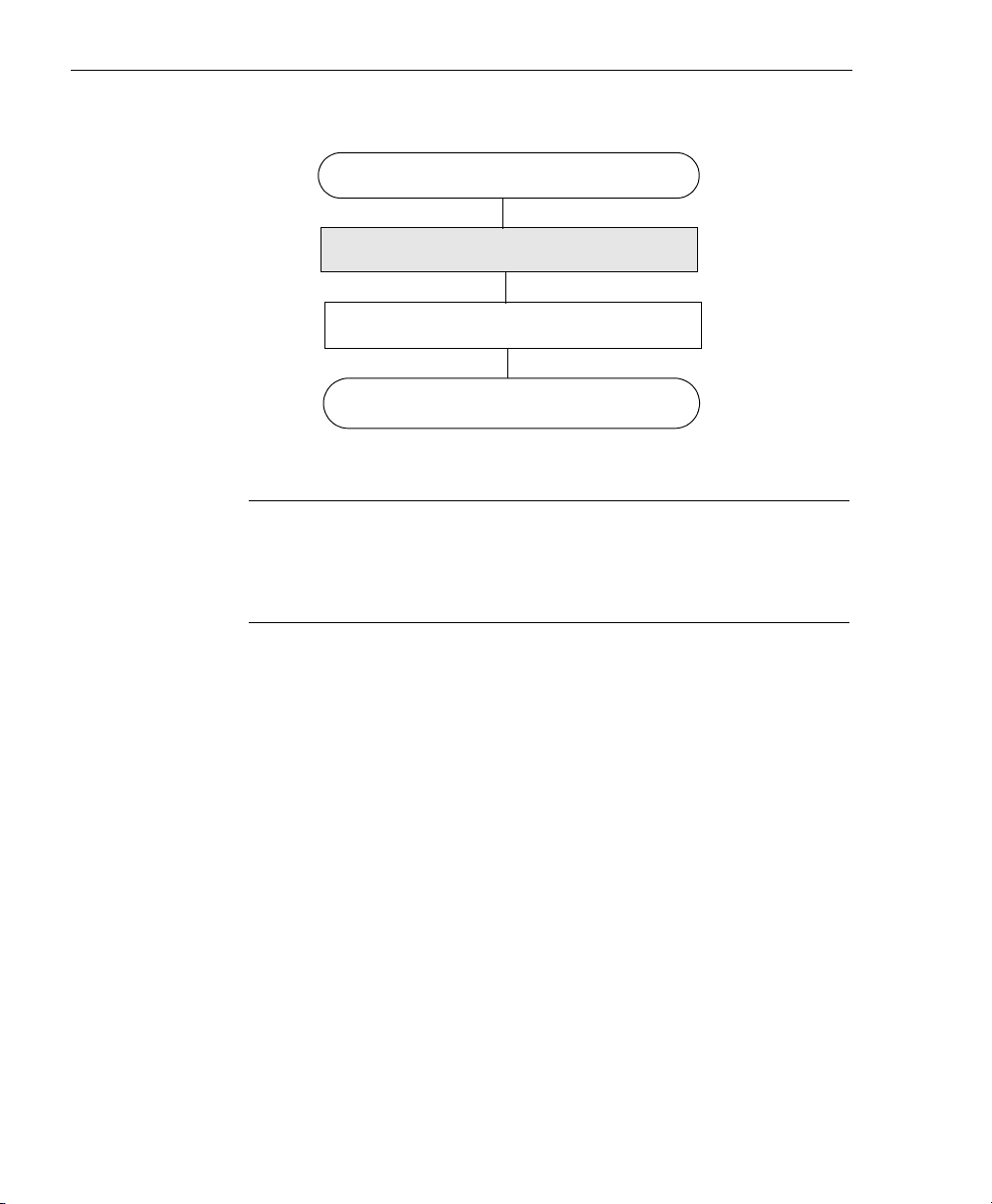
Prepare to Use the Module
(this chapter)
Set Up and Install the Module
(see Chapter 3 starting on page 29)
Wire Signals to the Module
(see Chapter 4 starting on page 37)
Verify the Operation of the Module
(see Chapter 5 starting on page 53)
Unpacking
Open the shipping box and verify that the following items are
present:
• DT9812-2.5V, DT9812-10V, DT9813-10V, or DT9814-10V module
24
• ECON CD
•USB cable
If an item is missing or damaged, contact Data Translation. If you are
in the United States, call the Customer Service Department at (508)
481-3700. An application engineer will guide you through the
appropriate steps for replacing missing or damaged items. If you are
located outside the United States, call your local distributor, listed on
Data Translation’s web site (www.datatranslation.com).
Once you have unpacked your module, check the system
requirements, as described in the next section.
Page 25

Preparing to Use a Module
Checking the System Requirements
For reliable operation, your DT9812, DT9813, and DT9814 modules
require the following:
• Windows 2000 or Windows XP (Professional Edition) operating
system.
For USB Ver. 2.0 support, make sure that you install Service Pack
2 (for Windows XP) or Service Pack 4 (for Windows 2000). In
addition, for some systems, you may have to disable standby
mode. If you are not sure whether you are using USB Ver. 1.1 or
Ver. 2.0, run the Open Layers Control Panel applet, described on
page 31.
2
2
2
• One or more USB ports (Ver. 2.0 or Ver. 1.1). USB Ver. 2.0 is
recommended for optimal performance.
•One CD-ROM drive.
Once you have verified that your system meets the system
requirements, install the software, as described in the next section.
2
2
2
2
2
2
25
Page 26

Chapter 2
Installing the Software
Note: Even if you already have a previous DT9812 Series module
and associated drivers installed, you must install the latest driver
software to support any DT9812 Series module you add to your
system.
To install the device driver, Data Acq SDK, DTx-EZ, and the GO!
application, do the following:
1. Insert the ECON CD into your CD-ROM drive.
If the software runs automatically (the default condition),
continue with step 4.
2. If the software does not run automatically, click Start from the
Task Bar, and then click Run.
The Run dialog box appears.
3. In the Command Line edit box, enter D:\Setup.Exe.
If your CD-ROM is not in drive D:, enter the letter of the drive where
your CD-ROM is located. The welcome screen appears.
26
4. Click Install Drivers and GO!
5. Click Install now!
The installation wizard appears.
6. Click Next.
The wizard prompts you for the destination location.
7. Either change the directory path and/or name using Browse or
accept the default directory (C:\Program Files\Data Translation),
and then click Next.
8. Click Next to copy the files.
9. Click Finish.
Page 27

Preparing to Use a Module
10. If you want to download and install an evaluation version of DT
Measure Foundry, do the following:
a. Click Install Additional Software, and then click Download
now! under the DT Measure Foundry section.
2
b. Click the Open option from the Internet Explorer File
Download dialog box.
The setup program of DT Measure Foundry evaluation is
automatically downloaded and started.
c. Follow the installation prompts.
11. If you want to install DT-LV Link, click Install Additional
Software, and then click Install now! under the LabVIEW Link
section, and follow the installation prompts.
12. When you have finished the installation process, click Quit
Installer.
Continue with the instructions in Chapter 3 starting on page 29.
2
2
2
2
2
2
2
2
27
Page 28

Chapter 2
28
Page 29

3
Setting Up and Installing
the Module
Attaching Modules to the Computer. . . . . . . . . . . . . . . . . . . . . . . 31
Changing the Name of a Module (Optional) . . . . . . . . . . . . . . . . 35
29
Page 30
Chapter 3
Prepare to Use the Module
(see Chapter 2 starting on page 23)
Set Up and Install the Module
(this chapter)
Wire Signals to the Module
(see Chapter 4 starting on page 37)
Verify the Operation of the Module
(see Chapter 5 starting on page 53)
Note: The DT9812, DT9813, and DT9814 modules are
factory-calibrated. The DT9812-2.5V module requires no further
adjustment. If you want to recalibrate the DT9812-10V, DT9813-10V,
or DT9814-10V module, refer to instructions on page 151.
30
Page 31

Setting Up and Installing the Module
Attaching Modules to the Computer
This section describes how to attach a module to the host computer.
3
Note: Most computers have several USB ports that allow direct
connection to USB devices. If your application requires more
modules than you have USB ports for, you can expand the number
of USB devices attached to a single USB port by using expansion
hubs. For more information, refer to page 33.
You can unplug a module, and then plug it in again, if you wish,
without causing damage. This process is called hot-swapping. Your
application may take a few seconds to recognize a module once it is
plugged back in.
You must install the device driver before connecting your module to
the host computer. See “Installing the Software” on page 26.
Connecting Directly to the USB Ports
To connect DT9812, DT9813, or DT9814 modules directly to the USB
ports of your computer, do the following:
1. Attach one end of the USB cable to the USB port on the module.
2. Attach the other end of the USB cable to one of the USB ports on
the host computer, as shown in Figure 2.
The operating system automatically detects the USB module and starts
the Found New Hardware wizard.
3
3
3
3
3
3
3
3
31
Page 32

Chapter 3
DT9812-2.5V, DT9812-10V, DT9813-10V,
or DT9814-10V Modules
USB Ports
Host Computer
USB Cable
Figure 2: Attaching the Module to the Host Computer
3. Click Next and/or Finish as required in the wizard.
If the module is attached correctly, the LED on the module turns green.
4. Repeat the steps to attach another module to the host computer,
if desired.
32
Page 33

Connecting to an Expansion Hub
Setting Up and Installing the Module
Expansion hubs are powered by their own external power supply.
Theoretically, you can connect up to five expansion hubs to a USB
port on the host computer. However, the practical number of DT9812,
DT9813, and/or DT9814 modules that you can connect to a single
USB port depends on the throughput you want to achieve. Each of
the hubs supports up to four modules.
To connect multiple modules to an expansion hub, do the following:
1. Attach one end of the USB cable to the module and the other end
of the USB cable to an expansion hub.
2. Connect the power supply for the expansion hub to an external
power supply.
3. Connect the expansion hub to the USB port on the host computer
using another USB cable.
The operating system automatically detects the USB device and starts
the Found New Hardware wizard.
4. Click Next and/or Finish as required in the wizard.
If the module is attached correctly, the LED on the module turns green.
5. Repeat these steps until you have attached the number of
expansion hubs (up to five) and modules (up to four per hub)
that you require. Refer to Figure 3.
The operating system automatically detects the USB devices as they are
installed.
3
3
3
3
3
3
3
3
3
33
Page 34

Chapter 3
ECONseries Module
USB Cables
Host Computer
USB Cable
Power Supply
for Hub
ECONseries Module
USB Cables
ECONseries Module
USB Cable
Expansion Hubs
Power Supply
for Hub
ECONseries Module
Figure 3: Attaching Multiple DT9812, DT9813, and/or DT9814 Modules
Using Expansion Hubs
34
Page 35

Setting Up and Installing the Module
Changing the Name of a Module (Optional)
To change the name of a module, configure the device driver as
follows:
1. From the Windows Start menu, select Settings|Control Panel.
2. From the Control Panel, double-click Open Layers Control
Panel.
The Data Acquisition Control Panel dialog box appears.
3. Click the DT9812, DT9813, or DT9814 module that you want to
rename, and then click Edit Name.
3
3
3
4. Enter a new name for the module, and then click OK. The name
is used to identify the module in all subsequent applications.
5. When you are finished configuring the module, click Close.
6. Repeat steps 3 to 5 for the other modules that you want to
configure.
7. Close the Data Acquisition Control Panel dialog box.
Continue with the instructions on wiring in Chapter 4 starting on
page 37.
3
3
3
3
3
3
35
Page 36

Chapter 3
36
Page 37

4
Wiring Signals to the Module
Preparing to Wire Signals . . . . . . . . . . . . . . . . . . . . . . . . . . . . . . . . 39
Connecting Analog Input Signals . . . . . . . . . . . . . . . . . . . . . . . . . 43
Connecting Analog Output Signals. . . . . . . . . . . . . . . . . . . . . . . . 44
Connecting Digital I/O Signals . . . . . . . . . . . . . . . . . . . . . . . . . . . 45
Connecting Counter/Timer Signals . . . . . . . . . . . . . . . . . . . . . . . 47
37
Page 38

Chapter 4
Prepare to Use a Module
(see Chapter 2 starting on page 23)
Set Up and Install the Module
(see Chapter 3 starting on page 29)
Wire Signals to the Module
(this chapter)
Verify the Operation of the Module
(see Chapter 5 starting on page 53)
38
Page 39

Preparing to Wire Signals
CAUTION:
Wiring Signals to the Module
4
To avoid electrostatic sensitivity, unplug your DT9812, DT9813, or
DT9814 module from the computer before wiring signals.
This section provides information about wiring signals to a
DT9812-2.5V, DT9812-10V, DT9813-10V, or DT9814-10V module.
Wiring Recommendations
Keep the following recommendations in mind when wiring signals to
an ECONseries module:
• Use individually shielded twisted-pair wire (size 16 to 26 AWG)
in highly noisy electrical environments.
• Separate power and signal lines by using physically different
wiring paths or conduits.
• To avoid noise, do not locate the box and cabling next to sources
that produce high electromagnetic fields, such as large electric
motors, power lines, solenoids, and electric arcs, unless the
signals are enclosed in a mumetal shield.
• Prevent electrostatic discharge to the I/O while the box is
operational.
4
4
4
4
4
4
• Connect all unused analog input channels to analog ground.
Wiring Locations
You wire signals to each module using the screw terminals on the
module. Tabl e 4 lists the screw terminal assignments for the DT9812
modules; Table 5 the DT9813 module; Tab le 6 the DT9814 module.
4
4
39
Page 40

Chapter 4
Table 4: DT9812-2.5V and DT9812-10V Screw Terminal
Assignments
Screw
Terminal
20 USB +5 V Out 40 Ext Trigger
19 Ground 39 Ext Clock
18 Counter 0 In 38 Ground
17 Counter 0 Out 37 Digital Output 7
16 Counter 0 Gate 36 Digital Output 6
15 Ground 35 Digital Output 5
14 DAC 1 34 Digital Output 4
13 DAC 1 Return 33 Digital Output 3
12 DAC 0 32 Digital Output 2
11 DAC 0 Return 31 Digital Output 1
10 2.5 V Reference
9 Analog Ground 29 Ground
8 Analog Input CH7 28 Digital Input 7
7 Analog Input CH6 27 Digital Input 6
Signal
a
Screw
Terminal
30 Digital Output 0
Signal
40
6 Analog Input CH5 26 Digital Input 5
5 Analog Input CH4 25 Digital Input 4
4 Analog Input CH3 24 Digital Input 3
3 Analog Input CH2 23 Digital Input 2
2 Analog Input CH1 22 Digital Input 1
1 Analog Input CH0 21 Digital Input 0
a. For the DT9812-10V module, this reference is 2.5 V. For the DT9812-2.5V
module, this reference is 2.44 V.
Page 41

Wiring Signals to the Module
Table 5: DT9813-10V Screw Terminal Assignments
Screw
Terminal
Signal
Screw
Terminal
4
Signal
20 USB +5 V Out 40 Ext Trigger
19 Ground 39 Ext Clock
18 Counter 0 In 38 Ground
17 Counter 0 Out 37 Digital Input 3
16 Counter 0 Gate 36 Digital Input 2
15 Ground 35 Digital Input 1
14 DAC 1 34 Digital Input 0
13 DAC 1 Return 33 Digital Output 3
12 DAC 0 32 Digital Output 2
11 DAC 0 Return 31 Digital Output 1
10 2.5 V Reference 30 Digital Output 0
9 Analog Ground 29 Ground
8 Analog Input CH7 28 Analog Input CH15
7 Analog Input CH6 27 Analog Input CH14
6 Analog Input CH5 26 Analog Input CH13
5 Analog Input CH4 25 Analog Input CH12
4
4
4
4
4
4
4 Analog Input CH3 24 Analog Input CH11
3 Analog Input CH2 23 Analog Input CH10
2 Analog Input CH1 22 Analog Input CH9
1 Analog Input CH0 21 Analog Input CH8
4
4
41
Page 42

Chapter 4
Table 6: DT9814-10V Screw Terminal Assignments
Screw
Terminal
20 USB +5 V Out 40 Ext Trigger
19 Ground 39 Ext Clock
18 Counter 0 In 38 Ground
17 Counter 0 Out 37 Analog Input CH23
16 Counter 0 Gate 36 Analog Input CH22
15 Ground 35 Analog Input CH21
14 DAC 1 34 Analog Input CH20
13 DAC 1 Return 33 Analog Input CH19
12 DAC 0 32 Analog Input CH18
11 DAC 0 Return 31 Analog Input CH17
10 2.5 V Reference 30 Analog Input CH16
9 Analog Ground 29 Ground
8 Analog Input CH7 28 Analog Input CH15
7 Analog Input CH6 27 Analog Input CH14
Signal
Screw
Terminal
Signal
42
6 Analog Input CH5 26 Analog Input CH13
5 Analog Input CH4 25 Analog Input CH12
4 Analog Input CH3 24 Analog Input CH11
3 Analog Input CH2 23 Analog Input CH10
2 Analog Input CH1 22 Analog Input CH9
1 Analog Input CH0 21 Analog Input CH8
Page 43

Wiring Signals to the Module
Connecting Analog Input Signals
The DT9812-2.5V and DT9812-10V modules support 8 single-ended
analog input channels. The DT9813-10V module supports 16
single-ended analog input channels; the DT9814-10V supports 24.
4
Figure 4 shows how to connect single-ended voltage input signals
(channels 0 and 1, in this case) to the screw terminals of the module.
Analog Ground
-
source 1
V
-
Vsource 0
Signal Source
Figure 4: Connecting Single-Ended Inputs
+
Analog In 1
+
Analog In 0
9
2
1
ECONseries Module
4
4
4
4
4
4
4
4
43
Page 44

Chapter 4
Connecting Analog Output Signals
The DT9812, DT9813, and DT9814 modules support two analog
output channels (DAC0 and DAC1). Figure 5 shows how to connect
an analog output voltage signal (DAC0, in this case) to one of these
modules.
Load
DAC0
DAC0 Return
12
11
ECONseries Module
Figure 5: Connecting Analog Outputs to a Screw Terminal Panel
44
Page 45

Connecting Digital I/O Signals
The DT9812-2.5V and DT9812-10V modules support eight fixed
digital input lines and eight fixed digital output lines. The
DT9813-10V module supports four fixed digital input lines and four
fixed digital output lines.
Figure 6 shows how to connect digital input signals (lines 0 and 1, in
this case) to the screw terminals of a DT9812-2.5V or DT9812-10V
module.
Wiring Signals to the Module
4
4
4
29
22
21
DT9812-2.5V or
DT9812-10V Module
Figure 6: Connecting Digital Inputs
For a DT9813-10V module, connect digital input lines 0 and 1 to
screw terminals 34 and 35, respectively.
Ground
Digital Input 1
Digital Input 0
TTL Inputs
4
4
4
4
4
4
45
Page 46

Chapter 4
Figure 7 shows how to connect digital output signals (line 0, in this
case) to the screw terminals of a DT9812-2.5V, DT9812-10V, or
DT9813-10V module.
38
30
DT9812 Series or
DT9813 Module
Ground
Out = LED On
Digital Output 0
500 Ω
+
5 V
-
Figure 7: Connecting Digital Outputs
Note: The DT9813-10V module has only four digital output lines, at
screw terminals 30 through 33.
46
Page 47

Wiring Signals to the Module
Connecting Counter/Timer Signals
The DT9812, DT9813, and DT9814 modules provide one
counter/timer that you can use for the following operations:
• Event counting
• Frequency measurement
• Edge-to-edge measurement
4
4
• Continuous pulse output (rate generation)
This section describes how to connect counter/timer signals for these
operation modes. Refer to Chapter 6 for more information about
using the counter/timers.
Event Counting
Figure 8 shows how to connect counter/timer signals to the screw
terminals on the module to perform an event counting operation
using an external gate.
In this example, the counter counts the number of rising edges that
occur on the Counter 0 In signal when the Counter 0 Gate signal is in
the active state (as specified by software). Refer to “Counter/Timer
Features” on page 91 for more information.
4
4
4
4
4
4
4
47
Page 48

Chapter 4
Signal
Source
Ground
19
Counter 0 In
External
Gating
Switch
Counter
0 Gate
Ground
18
16
ECONseries Module
Figure 8: Connecting Counter/Timer Signals for an Event Counting
Operation Using an External Gate
Figure 9 shows how to connect counter/timer signals to the screw
terminals on the module to perform an event counting operation
without using a gate (also called a software gate). The counter counts
the number of rising edges that occur on the Counter 0 In signal.
Ground
Signal
Source
ECONseries Module
19
48
Counter 0 In
18
Figure 9: Connecting Counter/Timer Signals for an Event Counting
Operation Without Using a Gate
Page 49

Frequency Measurement
Wiring Signals to the Module
Signal
Source
One way to measure frequency is to use the same wiring as a
standard event counting application that does not use a gate (see
Figure 9), and then call the olDaMeasureFrequency function to
determine the duration over which to count the number of pulses
connected to the Counter 0 In signal. The frequency of the Counter 0
In signal is the number of counts divided by the duration of the
olDaMeasureFrequency function.
If you need more accuracy than the olDaMeasureFrequency function
provides, you can connect a pulse of a known duration to the Counter
0 Gate signal, as shown in Figure 10. In this case, the frequency of the
Counter 0 In signal is the number of counts divided by the period of
the signal connected to the Counter 0 Gate input.
Ground
Counter 0 In
(Number of pulses counted
during gate period)
Counter 0 Gate
Known Signal
Source
(Determines period
for count)
ECONseries Module
19
18
16
4
4
4
4
4
4
4
Figure 10: Connecting Counter/Timer Signals for a Frequency Measurement
Operation Using an External Pulse
4
4
49
Page 50

Chapter 4
Edge-to-Edge Measurement
Figure 11 shows how to connect counter/timer signals to the module
to perform an edge-to-edge measurement operation on one signal
source. The counter measures the number of counts between the start
edge (in this case, a rising edge on the Counter 0 Gate signal) and the
stop edge (in this case, another rising edge on the Counter 0 Gate
signal).
You specify the start edge and the stop edge in software. Refer to
page 96 for more information.
ECONseries Module
Ground
Signal Source
Counter 0 Gate
In this example, the software
returns the number of counts
between the two rising edges
Figure 11: Connecting Counter/Timer Signals for an
Edge-to-Edge Measurement Operation
19
16
50
Page 51

Wiring Signals to the Module
You can use edge-to-edge measurement to measure the following
characteristics of a signal:
• Pulse width – The amount of time that a signal pulse is in a high
or a low state, or the amount of time between a rising edge and a
falling edge or between a falling edge and a rising edge. You can
calculate the pulse width as follows:
− Pulse width = Number of counts/24 MHz
• Period – The time between two occurrences of the same edge
(rising edge to rising edge, or falling edge to falling edge). You
can calculate the period as follows:
− Period = 1/Frequency
4
4
4
− Period = Number of counts/24 MHz
• Frequency – The number of periods per second. You can
calculate the frequency as follows:
− Frequency = 24 MHz/Number of Counts
4
4
4
4
4
4
51
Page 52

Chapter 4
Rate Generation
Figure 12 shows how to connect counter/timer signals to the screw
terminals of a module to perform a rate generation (continuous pulse
output) operation; in this example, an external gate is used.
Heater
Controller
Ground
Counter 0 Out
External
Gating
Switch
Counter 0
Gate
Ground
ECONseries Module
19
17
16
Figure 12: Connecting Counter/Timer Signals for a Rate Generation
Operation Using an External Gate
52
Page 53

5
Verifying the Operation
of a Module
Overview . . . . . . . . . . . . . . . . . . . . . . . . . . . . . . . . . . . . . . . . . . . . . . 55
Using the Oscilloscope Function . . . . . . . . . . . . . . . . . . . . . . . . . . 57
Using the Chart Recorder Function. . . . . . . . . . . . . . . . . . . . . . . . 58
Using the Voltmeter Function. . . . . . . . . . . . . . . . . . . . . . . . . . . . . 59
Using the File Viewer Function . . . . . . . . . . . . . . . . . . . . . . . . . . . 60
Using the Waveform Generator Function. . . . . . . . . . . . . . . . . . . 61
Using the Digital Input Function . . . . . . . . . . . . . . . . . . . . . . . . . . 62
Using the Digital Output Function . . . . . . . . . . . . . . . . . . . . . . . . 63
Using the Counter Function . . . . . . . . . . . . . . . . . . . . . . . . . . . . . . 64
Using the Rate Generator Function . . . . . . . . . . . . . . . . . . . . . . . . 65
53
Page 54

Chapter 5
Prepare to Use a Module
(see Chapter 2 starting on page 23)
Set Up and Install the Module
(see Chapter 3 starting on page 29)
Wire Signals to the Module
(see Chapter 4 starting on page 37)
Verify the Operation of the Module
(this chapter)
54
Page 55

Overview
The GO! application allows you to measure and control signals from
your DT9812-2.5V, DT9812-10V, DT9813-10V, and DT9814-10V
modules right out of the box. Simply install the ECONseries software,
connect your module to the PC, connect your signals to the module,
and run the GO! application from the Data Translation, Inc|
ECONseries program group.
Verifying the Operation of a Module
5
5
The GO! application provides the following instrument-like functions
for data acquisition, control, and display (the software shows only
those functions that are supported by your module):
• Oscilloscope
− Stream, plot, and analyze data from up to eight analog input
channels
− Zoom in or out of live signals
− Select the trigger type, level, and channel
− Print your data or save it to an Excel file
• Chart Recorder
− Record up to 31,990 data points from up to eight analog input
channels
− Log data to an Excel file
•Voltmeter
− Measure data from up to eight analog input channels and
view it in a 5-digit digital display
− Display the maximum or true root mean square (RMS) value
• File Viewer
5
5
5
5
5
5
− Load a previously saved Excel file
− Scroll, zoom, or print your data
5
55
Page 56

Chapter 5
• Function Generator
− Generate DC, sine, rectangle, or triangle waveforms from up
to two analog output channels
− Select the frequency, amplitude, offset, and duty cycle of your
signal
• Digital Input − Monitor the status of the digital inputs using
LEDs
• Digital Output − Control the state of the digital outputs using
switches
• Counter − Count pulses from the counter/timer for 1, 2, or 5
seconds or for an unlimited time
• Rate Generator − Control the frequency of a continuous pulse
output signal from the counter/timer
The GO! application automatically detects and configures the first
installed ECONseries module. If you have multiple ECONseries
modules installed, you can select the module to use.
56
Notes: If no module is connected, the GO! application displays a
message box. If you want to continue, plug a DT9812, DT9813, or
DT9814 module into any USB port of your PC, and then click
Rescan. Otherwise, click Quit to exit from the GO! application.
If you have multiple modules, you can run multiple instances of the
GO! application, if you wish. Each instance of the application detects
the available (not already in use) modules for your convenience.
Press F1 at any time to get help on any of the functions of the GO!
application.
Page 57

Verifying the Operation of a Module
Using the Oscilloscope Function
The verify the analog input operation of your module using the
Oscilloscope function of the GO! application, do the following:
1. Connect a known voltage source, such as the output of a function
generator, to analog input channel 0 on the module (single-ended
mode). Refer to page 43 for an example of how to connect a
single-ended analog input.
5
5
2. Under Visible Channels on the Oscilloscope tab, ensure that only
channel 0 is selected.
The analog input data from channel 0 is continuously displayed.
3. Zoom into your data by using your left mouse button to create a
zoom rectangle around the region that you are interested in.
4. When you are finished, snap back to the standard voltage range
of the module, by clicking the Unzoom button.
5
5
5
5
5
5
5
57
Page 58

Chapter 5
Using the Chart Recorder Function
To verify the analog input operation of your module using the Chart
Recorder function of the GO! application, do the following:
1. Connect a known voltage source, such as the output of a function
generator, to analog input channel 0 on the module (single-ended
mode). Refer to page 43 for an example of how to connect a
single-ended analog input.
2. Under Visible Channels on the Chart Recorder tab, ensure that
only channel 0 is selected.
3. Click Start Recording, and enter Te st for the filename.
The analog input data from channel 0 is displayed on the screen and
logged to the Test.xls file.
4. After a few seconds, click Stop Recording.
5. Launch Excel and open the file called Test.xls to review the data
you just recorded.
58
Page 59

Using the Voltmeter Function
To verify the analog input operation of your module using the
Voltmeter function of the GO! application, do the following:
1. Connect a known voltage source, such as the output of a function
generator, to analog input channel 0 on the module (single-ended
mode). Refer to page 43 for an example of how to connect a
single-ended analog input.
Verifying the Operation of a Module
5
5
2. Under Visible Channels on the Voltmeter tab, ensure that only
channel 0 is selected.
3. Click Normal under Display Settings.
The analog input data from analog input channel 0 is converted into
digital format and displayed.
Note that the 5-digit display is refreshed twice a second.
5
5
5
5
5
5
5
59
Page 60

Chapter 5
Using the File Viewer Function
To verify the analog input operation of your module using the File
Viewer function of the GO! application, do the following:
1. Connect a known voltage source, such as the output of a function
generator, to analog input channel 0 on the module (single-ended
mode). Refer to page 43 for an example of how to connect a
single-ended analog input.
2. Under Visible Channels on the Chart Recorder tab, ensure that
only channel 0 is selected.
3. Click Start Recording, and enter Te st for the filename.
The analog input data from channel 0 is displayed on the screen and
logged to the Test.xls file.
4. After a few seconds, click Stop Recording.
5. Click on the File Viewer tab, and click Open File.
6. Click on the filename Te s t .x l s .
7. Click Open.
60
8. Scroll through the data in the file using the slider at the bottom of
the File Viewer screen.
Page 61

Verifying the Operation of a Module
Using the Waveform Generator Function
To verify the analog output operation of your module using the
Waveform Generator function of the GO! application, do the
following:
5
1. Connect an oscilloscope or voltmeter to analog output channel 0
on the module. Refer to page 44 for an example of how to connect
analog output signals.
2. For Waveform Ch0, select Sine.
Notice the waveform that is output on your oscilloscope or voltmeter
display.
3. If you wish, use the Amplitude sliders for Ch 0 to change the
amplitude of the waveform. For the DT9812-2.5V module, the
amplitude can range between 0 and 2.44 V.
For the DT9812-10V, DT9813-10V, and DT9814-10V modules, the
amplitude can range between −10 V and +10 V.
4. If you wish, use the Frequency sliders for Ch 0 to change the
frequency of the module. The frequency of both modules can
range between 0 and 50 kHz.
5. If you wish, use the Offset sliders for Ch 0 to change the offset of
the module. For the DT9812-2.5V module, the offset can range
between 0 and 2.44 V.
For the DT9812-10V, DT9813-10V, and DT9814-10V modules, the
offset can range between −10 V and +10 V.
5
5
5
5
5
5
5
5
61
Page 62

Chapter 5
Using the Digital Input Function
To verify the digital input operation of your DT9812-2.5V,
DT9812-10V, or DT9813-10V module using the Digital Input function
of the GO! application, do the following:
1. Connect a digital input signal to a digital input line on the
module. Refer to page 45 for an example of how to connect a
digital input.
2. Read the status of the LEDs.
If digital input line 0 is high, the LED for line 0 turns green (on). If
digital input line 0 is low, the LED for line 0 turns gray (off).
The DT9812-2.5V and DT9812-10V modules support eight fixed
digital input lines. The DT9813-10V supports four fixed digital input
lines.
62
Page 63

Verifying the Operation of a Module
Using the Digital Output Function
To verify the digital output operation of your DT9812-2.5V,
DT9812-10V, or DT9813-10V module using the Digital Output
function of the GO! application, do the following:
5
1. Connect a device to a digital output line on the module. Refer to
page 45 for an example of how to connect a digital output.
2. Click the switches to change the state of your device.
3. Check that the device has been changed as expected.
For example, if you connect a simple set of LEDs, the LED
corresponding to a line you switch on with the Digital Output function
should turn green (on).
The DT9812-2.5V and DT9812-10V modules support eight fixed
digital output lines. The DT9813-10V supports four fixed digital
output lines.
5
5
5
5
5
5
5
5
63
Page 64

Chapter 5
Using the Counter Function
To verify the event counting operation of your module using the
Counter function of the GO! application, do the following:
1. Wire an external clock source to the Counter 0 In signal on your
module. (Refer to page 47 for an example of how to connect an
external clock to the counter/timer channel.)
2. Click 2 Seconds, and click Start Counting.
The number of counts is displayed on the screen.
When 2 seconds have elapsed, the operation stops automatically.
64
Page 65

Verifying the Operation of a Module
Using the Rate Generator Function
To verify the rate generation operation of your module using the Rate
Generator function of the GO! application, do the following:
1. Connect a scope or similar device that accepts a pulse output
signal to the Counter 0 Out signal of your module. (Refer to page
52 for an example of how to connect signals for rate generation.)
2. Use the slider to change the frequency of the continuous pulse
output signal.
If you are using a scope, you can see the frequency of the pulse output
signal change as you move the slider.
5
5
5
5
5
5
5
5
5
65
Page 66

Chapter 5
66
Page 67

Part 2: Using Your Module
Page 68

Page 69

6
Principles of Operation
Analog Input Features . . . . . . . . . . . . . . . . . . . . . . . . . . . . . . . . . . . 73
Analog Output Features . . . . . . . . . . . . . . . . . . . . . . . . . . . . . . . . . 83
Digital I/O Features. . . . . . . . . . . . . . . . . . . . . . . . . . . . . . . . . . . . . 90
Counter/Timer Features . . . . . . . . . . . . . . . . . . . . . . . . . . . . . . . . . 91
69
Page 70

Chapter 6
Figure 13 shows a block diagram of the DT9812-2.5V and
DT9812-10V modules.
+2.5 V Reference*
8-Channel Multiplexer
A/D Ch7
A/D Ch6
A/D Ch5
A/D Ch4
A/D Ch3
A/D Ch2
A/D Ch1
A/D Ch0
ESD Protected to 4000 V
DAC 1
DAC 0
From USB
Por t
A/D Clock
12-Bit A/D
Converter
12-Bit D/A
Converter
Power
Supply
32-Bit
Counter/Timer
+5 V
C/T Out 0
C/T Gate 0
C/T In 0
External Clock
External Trigger
Digital
I/O
ESD Protected to 4000 V
DOUT7
DOUT0
DIN7
DIN0
70
USB 2.0 or 1.1
Por t
* Note: For the DT9812-10V module, the reference is 2.5 V.
For the DT9812-2.5V module, the reference is 2.44 V.
Input FIFO
Figure 13: Block Diagram of the DT9812-2.5V and DT9812-10V Modules
Page 71

Principles of Operation
Figure 14 shows a block diagram of the DT9813-10V module.
6
+2.5 V Reference
16-Channel Multiplexer
A/D Ch15
A/D Ch14
A/D Ch13
A/D Ch2
A/D Ch1
A/D Ch0
ESD Protected to 4000 V
DAC 1
DAC 0
From USB
Por t
A/D Clock
12-Bit A/D
Converter
12-Bit D/A
Converter
Power
Supply
32-Bit
Counter/Timer
+5 V
C/T Out 0
C/T Gate 0
C/T In 0
External Clock
External Trigger
Digital
I/O
ESD Protected to 4000 V
DOUT3
DOUT0
DIN3
DIN0
6
6
6
6
6
USB 2.0 Port
Figure 14: Block Diagram of the DT9813-10V Module
Input FIFO
6
6
6
71
Page 72

Chapter 6
Figure 15 shows a block diagram of the DT9814-10V module.
+2.5 V Reference
24-Channel Multiplexer
A/D Ch23
A/D Ch22
A/D Ch21
A/D Ch2
A/D Ch1
A/D Ch0
ESD Protected to 4000 V
DAC 1
DAC 0
From USB
Por t
A/D Clock
12-Bit A/D
Converter
12-Bit D/A
Converter
Power
Supply
32-Bit
Counter/Timer
+5 V
C/T Out 0
C/T Gate 0
C/T In 0
External Clock
External Trigger
ESD Protected to 4000 V
72
USB 2.0 Port
Input FIFO
Figure 15: Block Diagram of the DT9814-10V Module
Page 73

Analog Input Features
This section describes the following features of analog input (A/D)
operations on the DT9812, DT9813, and DT9814 modules:
• Input resolution, described below
• Analog input channels, described below
• Input ranges and gains, described on page 75
Principles of Operation
6
6
• Input sample clock sources, described on page 77
• Analog input conversion modes, described on page 78
• Input triggers, described on page 80
• Data format and transfer, described on page 81
• Error conditions, described on page 82
Input Resolution
The DT9812, DT9813, and DT9814 modules provide a resolution of
12-bits. Note that the resolution is fixed; you cannot program it in
software.
Analog Input Channels
The DT9812-2.5V and DT9812-10V modules provide eight
single-ended analog input channels. The DT9813-10V and
DT9814-10V modules provide 16 and 24 analog input channels,
respectively. The modules can acquire data from a single analog
input channel or from a group of analog input channels.
6
6
6
6
6
6
The following subsections describe how to specify the channels.
6
73
Page 74

Chapter 6
Specifying a Single Analog Input Channel
The simplest way to acquire data from a single analog input channel
is to specify the channel for a single-value analog input operation
using software; refer to page 78 for more information about
single-value operations.
You can also specify a single channel using the analog input
channel-gain list, described in the next section.
Specifying One or More Analog Input Channels
You can read data from one or more analog input channels using an
analog input channel-gain list. You can group the channels in the list
sequentially (starting either with 0 or with any other analog input
channel) or randomly. You can also specify a single channel or the
same channel more than once in the list.
Using software, specify the channels in the order you want to sample
them. You can enter up to 32 entries in the channel-gain list. The
channels are read in order from the first entry in the list to the last
entry in the list. Refer to page 78 for more information about the
supported conversion modes.
74
The maximum rate at which the module can read the analog input
channels is 50 kSamples/s. Therefore, if you specify two analog input
channels in the channel-gain list, the maximum sampling rate is
25 kSamples/s for each channel. Likewise, if you specify 16 analog
input channels in the channel-gain list, the maximum sampling rate is
3.125 kSamples/s for each channel.
Page 75

Input Ranges and Gains
Principles of Operation
The DT9812-2.5V features an input range of 0 to 2.44 V, while the
DT9812-10V, DT9813-10V, and DT9814-10V modules feature an input
range of ±10 V. Use software to specify the input range. Note that this
is the range for the entire analog input subsystem, not the range per
channel.
The modules support programmable gains to allow many more
effective input ranges. Tab le 7 lists the supported gains and effective
input ranges for each module.
Table 7: Effective Input Range
Unipolar
Module Gain
DT9812-2.5V 1 0 to 2.44 V
2 0 to 1.22 V −
4 0 to 0.610 V −
8 0 to 0.305 V −
16 0 to 0.1525 V −
Input Range
Bipolar
Input Range
−
6
6
6
6
6
6
DT9812-10V
DT9813-10V
DT9814-10V
1 − ±10 V
2
4
8
− ±5 V
− ±2.5 V
− ±1.25 V
6
6
6
75
Page 76

Chapter 6
For each channel on the module, choose the gain that has the smallest
effective range that includes the signal you want to measure. For
example, if you are using a DT9812-2.5V module and the range of
your analog input signal is 0 to 1.05 V, specify a range of 0 to 2.44 V
for the module and use a gain of 2 for the channel; the effective input
range for this channel is then 0 to 1.22 V, which provides the best
sampling accuracy for that channel.
The way you specify gain depends on how you specified the
channels, as described in the following subsections.
Specifying the Gain for a Single Channel
The simplest way to specify gain for a single channel is to specify the
gain for a single-value analog input operation using software; refer to
page 78 for more information about single-value operations.
You can also specify the gain for a single channel using an analog
input channel-gain list, described in the next section.
76
Specifying the Gain for One or More Channels
You can specify the gain for one or more analog input channels using
an analog input channel-gain list. Using software, set up the
channel-gain list by specifying the gain for each entry in the list.
For example, assume the analog input channel-gain list contains three
entries: channels 5, 6, and 7 and gains 2, 4, and 1. A gain of 2 is
applied to channel 5, a gain of 4 is applied to channel 6, and a gain of
1 is applied to channel 7.
Page 77

Input Sample Clock Sources
Principles of Operation
You can use one of the following clock sources to pace an analog
input operation:
• Internal clock – Using software, specify the clock source as
internal and the clock frequency at which to pace the operation.
The minimum frequency of the internal clock is 30 Hz; the
maximum frequency of the internal clock is 50 kHz.
According to sampling theory (Nyquist Theorem), specify a
frequency that is at least twice as fast as the input’s highest
frequency component. For example, to accurately sample a 2 kHz
signal, specify a sampling frequency of at least 4 kHz. Doing so
avoids an error condition called aliasing, in which high frequency
input components erroneously appear as lower frequencies after
sampling.
• External clock – An external clock is useful when you want to
pace acquisitions at rates not available with the internal clock or
when you want to pace at uneven intervals. The minimum
frequency of the external clock can be less than 30 Hz; the
maximum frequency of the external clock is 40 kHz.
Connect an external clock to the Ext Clock In signal on the
module. Conversions start on the rising edge of the external clock
input signal.
6
6
6
6
6
6
Using software, specify the clock source as external. The clock
frequency is always equal to the frequency of the external sample
clock input signal that you connect to the module.
6
6
6
77
Page 78

Chapter 6
Analog Input Conversion Modes
The DT9812, DT9813, and DT9814 modules support the following
conversion modes:
• Single-value operations
• Continuous scan operations
Single-Value Operations
Single-value operations are the simplest to use. Using software, you
specify the range, gain, and analog input channel. The module
acquires the data from the specified channel and returns the data
immediately. For a single-value operation, you cannot specify a clock
source, trigger source, scan mode, or buffer.
Single-value operations stop automatically when finished; you
cannot stop a single-value operation.
Continuous Scan Mode
78
Use continuous scan mode if you want to accurately control the
period between conversions of individual channels in a channel-gain
list.
When it receives a software trigger, the module cycles through the
channel-gain list, acquiring and converting the data for each entry in
the list (this process is defined as the scan). The module then wraps to
the start of the channel-gain list and repeats the process continuously
until either the allocated buffers are filled or until you stop the
operation. Refer to page 80 for more information about buffers.
Page 79

Principles of Operation
The conversion rate is determined by the frequency of the internal
sample clock; refer to page 77 for more information about the internal
sample clock. The sample rate, which is the rate at which a single
entry in the channel-gain list is sampled, is determined by the
frequency of the input sample clock divided by the number of entries
in the channel-gain list.
To select continuous scan mode, use software to specify the data flow
as continuous.
6
6
Figure 16 illustrates continuous scan mode using a channel-gain list
with three entries: channel 0, channel 1, and channel 2. In this
example, analog input data is acquired on each clock pulse of the
input sample clock. When it reaches the end of the channel-gain list,
the module wraps to the beginning of the channel-gain list and
repeats this process. Data is acquired continuously.
Chan 0
Input
Sample
Clock
Initial trigger event occurs
Chan 2
Chan 1
Figure 16: Continuous Scan Mode
Chan 0
Chan 1
Chan 2
Data acquired continuously
Chan 0
Chan 2
Chan 1
Chan 0
Chan 1
Chan 2
6
6
6
6
6
6
6
79
Page 80

Chapter 6
Input Triggers
A trigger is an event that occurs based on a specified set of
conditions. Acquisition starts when the module detects the initial
trigger event and stops when the specified number of samples has
been acquired (if the buffer wrap mode is none, described on page
80), or when you stop the operation. Note that when you stop the
operation, the module completes the reading of the channel-gain list.
The DT9812, DT9813, and DT9814 modules support the following
trigger sources:
• Software trigger
start the analog input operation (the computer issues a write to
the module to begin conversions). Using software, specify the
trigger source as a software trigger.
• External digital (TTL) trigger
event occurs when the module detects a high-to-low transition on
the Ext Trigger In signal connected to the module. Using
software, specify a falling-edge external digital trigger (trigger
source extra).
Data Transfer
Before you begin acquiring data, you must allocate buffers to hold
the data. A Buffer Done message is returned whenever a buffer is
filled. This allows you to move and/or process the data as needed.
We recommend that you allocate a minimum of three buffers for
analog input operations, specifying one of the following buffer wrap
modes in software:
• None
– Data is written to multiple allocated input buffers
continuously; when no more empty buffers are available, the
operation stops. If wrap mode is none, the module guarantees
gap-free data.
– A software trigger event occurs when you
– An external digital (TTL) trigger
80
Page 81

• Multiple – Data is written to multiple allocated input buffers
continuously; if no more empty buffers are available, the module
overwrites the data in the current buffer, starting with the first
location in the buffer. This process continues indefinitely until
you stop it. If wrap mode is multiple, the module does not
guarantee gap-free data.
Data Format
Principles of Operation
6
6
The DT9812-2.5V module uses binary data encoding to represent
unipolar input ranges, while the DT9812-10V, DT9813-10V, and
DT9814-10V modules use twos complement encoding to represent
bipolar input ranges.
In software, the analog input value is returned as a code. To convert
the code to voltage, use the information in the following subsections.
Converting a Binary Code to a Voltage
To convert a binary code into a voltage on the DT9812-2.5V module,
use the following formula:
Voltage = (2.44 * Code) / 4096
where,
• 2.44 is the full-scale range of the module (0 to +2.44V)
• Code is the raw count used by the software to represent the
voltage in binary notation
• 4096 is the input resolution (12 bits)
• Voltage is the analog voltage
6
6
6
6
6
6
For example, if the software returns a code of 3072 for the analog
input operation, determine the analog input voltage as follows:
Voltage = (2.44 * 3072) / 4096 = 1.83 V
6
81
Page 82

Chapter 6
Converting a Twos Complement Code to a Voltage
To convert a twos complement code into a voltage on the
DT9812-10V, DT9813-10V, or DT9814-10V module, use the following
formula:
Voltage = (20 * Code) / 4096
where,
• 20 is the full-scale range of the module (-10V to +10V)
• Code is the raw count used by the software to represent the
voltage
• 4096 is the input resolution (12 bits)
• Voltage is the analog voltage
For example, assume that the software returns a code of 1040 for the
analog input value. Determine the analog input voltage as follows:
Voltage = (20 * 1040) /4096 = 5.078 V
82
Error Conditions
An overrun condition is reported if the A/D sample clock rate is too
fast. This error is reported if a new A/D sample clock pulse occurs
while the ADC is busy performing a conversion from the previous
A/D sample clock pulse. It is up to the host application to handle this
error by either ignoring the error or stopping acquisition. To avoid
this error, use a slower sampling rate or increase the buffer size
and/or number of buffers.
Page 83

Analog Output Features
This section describes the following features of analog output
operations:
• Output resolution, described below
• Analog output channels, described below
• Output ranges and gains, described on page 84
Principles of Operation
6
6
• Output trigger, described on page 85
• Output clock, described on page 85
• Data format and transfer, described on page 88
• Error conditions, described on page 89
Output Resolution
The modules provide a fixed output resolution of 12 bits. Note that
the resolution is fixed; it cannot be programmed in software.
Analog Output Channels
DT9812, DT9813, and DT9814 modules provide two analog output
channels (DACs). The modules can output data from a single analog
output channel or from both analog output channels.
The following subsections describe how to specify the channels.
Specifying a Single Analog Output Channel
6
6
6
6
6
6
The simplest way to output data from a single analog output channel
is to use single-value analog output mode, specifying the analog
output channel that you want to update; refer to page 86 for more
information about single-value operations.
6
83
Page 84

Chapter 6
You can also specify a single analog output channel using the output
channel list, described in the next section.
Specifying Analog Output Channels
You can output data continuously from one or both analog output
channels using the output channel list. If you want to output data
from one analog output channel continuously, specify either 0
(DAC0) or 1 (DAC1) in the channel output list. If you want to output
data to both analog output channels continuously, specify the output
channel list in the following order: 0, 1.
Then, use software to specify the data flow mode as continuous for
the D/A subsystem; refer to page 85 for more information on
continuous analog output operations.
Output Ranges and Gains
For the DT9812-2.5V module, a fixed output range of 0 to 2.44 V is
provided. For the DT9812-10V, DT9813-10V, and DT9814-10V, a fixed
output range of ±10 V is provided.
84
Through software, specify the range for the entire analog output
subsystem (0 to 2.44 V for the DT9812-2.5 V module or ±1 0 V for the
DT9812-10V, DT9813-10V, and DT9814-10V modules), and specify a
gain of 1 for each channel.
Page 85

Output Trigger
Principles of Operation
A trigger is an event that occurs based on a specified set of
conditions. The modules support a software trigger for starting
analog output operations. Using a software trigger, the module starts
outputting data when it receives a software command.
Using software, specify the trigger source for the D/A subsystem as a
software trigger.
Output Clock
When in continuous output mode, described on page 86, you can
update both analog output channels simultaneously using the
internal clock on the module.
Using software, specify the clock source for the D/A subsystem as
internal and specify the frequency at which to update the analog
output channels (between 30 Hz to 50 kHz).
Note: The output clock frequency that you specify is frequency at
which both analog output channels are simultaneously updated.
6
6
6
6
6
6
Output Conversion Modes
The DT9812, DT9813, and DT9814 modules support the following
output conversion modes:
• Single-value output operations
• Continuous output operations
6
6
6
85
Page 86

Chapter 6
Single-Value Operations
Single-value operations are the simplest to use but offer the least
flexibility and efficiency. Use software to specify the analog output
channel, and the value to output from the analog output channel.
Since a single-value operation is not clocked, you cannot specify a
clock source, trigger source, or buffer.
Single-value operations stop automatically when finished; you
cannot stop a single-value operation.
Continuous Output Mode
Use continuously paced analog output mode if you want to
accurately control the period between D/A conversions or write a
waveform to one or more analog output channels.
Use software to configure the output channel list, as described on
page 83. Then, allocate a buffer that contains the values to write to the
analog output channels that are specified in the output channel list.
For example, if your output channel list contains DAC0 and DAC1,
specify your buffer as follows: first value for DAC0, first value for
DAC1, second value for DAC0, second value for DAC1, and so on.
86
When it receives the software trigger, the module starts writing
output values to the analog output channels specified in the output
channel list. The operation repeats continuously until either all the
data is output from the buffers (if buffer wrap mode is none) or you
stop the operation (if buffer wrap mode is multiple). Refer to page 88
for more information about buffer modes.
Note: Make sure that the host computer transfers data to the analog
output channels fast enough so that they do not empty completely;
otherwise, an underrun error results.
Page 87

Principles of Operation
To select continuously paced analog output mode, use software to
specify the data flow as continuous, the buffer wrap mode as none or
multiple, the trigger source and output clock as internal, and the
output clock frequency (between 30 Hz and 50 kHz).
6
To stop a continuously paced analog output operation, you can stop
sending data to the module, letting the module stop when it runs out
of data, or you can perform either an orderly stop or an abrupt stop
using software. In an orderly stop, the module finishes outputting the
specified number of samples, then stops; all subsequent triggers are
ignored. In an abrupt stop, the module stops outputting samples
immediately; all subsequent triggers are ignored.
Data Transfer
If you are using continuous output mode, you must allocate and fill
multiple buffers with the appropriate data before starting the
operation, and specify a buffer wrap mode in software.
The following buffer wrap modes are supported:
• None – Data is written from multiple output buffers
continuously; when no more buffers of data are available, the
continuous output operation stops. This mode guarantees
gap-free data.
• Multiple – Data is written from multiple output buffers
continuously; when no more buffers of data are available, the
module returns to the first location of the first buffer and
continues writing data. This process continues indefinitely until
you stop it. This mode does not guarantee gap-free data.
A Buffer Done message is returned whenever the last value in a
buffer is output. This allows you to fill the buffer or provide a new
buffer, as needed.
6
6
6
6
6
6
6
6
87
Page 88

Chapter 6
Note: An underrun error can result if your buffer size is too small,
if you do not allocate enough buffers, or if your clock rate is too fast.
Data Format
The DT9812-2.5V module uses binary data encoding, while the
DT9812-10V, DT9813-10V, and DT9814-10V modules use twos
complement encoding.
In software, you need to supply a code that corresponds to the analog
output value you want the module to output.
Converting a Voltage into a Binary Code
To convert a voltage into a binary code on the DT9812-2.5V module,
use the following formula:
Code = Voltage / (2.44 / 4096)
88
where,
• 2.44 is the full-scale range of the module (0 to +2.44V)
• 4096 is the resolution (12 bits)
• Voltage is the analog output voltage
• Code is the raw count used by the software to represent the
voltage in binary notation
For example, if you want to output a voltage of 2.0 V, determine the
code value as follows:
Code = 2.0 / (2.44 / 4096) = 3357
Page 89

Principles of Operation
Converting a Voltage to a Twos Complement Code
To convert a voltage into a twos complement code on the
DT9812-10V, DT9813-10V, or DT9814-10V module, use the following
formula:
Code = Voltage / (20 / 4096)
where,
• 20 is the full-scale range of the module (-10V to +10V)
• 4096 is the resolution (12 bits)
• Voltage is the analog output voltage
• Code is the raw count used by the software to represent the
voltage in binary notation
For example, if you want to output a voltage of +5 V, determine the
code as follows
Code = 5/ (20 / 4096) = 1024
Error Conditions
6
6
6
6
6
6
The modules can report an underrun error if the data for the analog
output channels is not sent fast enough from the host computer. It is
up to the host application to handle this error either by ignoring it or
by stopping the output operation.
To avoid this error, try slowing down the clock rate, increasing the
output buffer size, or allocating more output buffers.
Note: If no new data is available to be output by the analog output
channels, the last value that was written to the analog output
channels continues to be output.
6
6
6
89
Page 90

Chapter 6
Digital I/O Features
This section describes the following features of digital I/O
operations:
• Digital I/O lines
•Resolution
•Operation modes
Digital I/O Lines
The DT9812-2.5V and DT9812-10V modules provide 8 dedicated
digital input lines and 8 dedicated digital output lines. The
DT9813-10V module provides 4 dedicated digital input lines and 4
dedicated digital output lines.
Using DT-Open Layers, you can specify the digital line that you want
to read or write in a single-value digital I/O operation. Refer to page
91 for more information about single-value operations.
90
A digital line is high if its value is 1; a digital line is low if its value is
0. On power up or reset, a low value (0) is output from each of the
digital output lines.
Note: You can also read or write to the digital I/O lines using direct
register calls. Refer to Appendix C for more information on these
calls.
Resolution
The resolution of the digital ports on the DT9812-2.5V and
DT9812-10V modules is fixed at 8-bits. The resolution of the digital
ports on the DT9813-10V module is fixed at 4-bits.
Page 91

Operation Modes
Principles of Operation
The DT9812 and DT9813 modules support single-value digital I/O
operations only. For a single-value operation, use software to specify
the digital I/O port (the gain is ignored). Data is then read from or
written to the digital lines associated with that port.
Single-value operations stop automatically when finished; you
cannot stop a single-value operation.
Counter/Timer Features
This section describes the following features of counter/timer (C/T)
operations:
• C/T channels, described below
• C/T clock sources, described on page 92
• Gate types, described on page 93
• Pulse types and duty cycles, described on page 93
• C/T operation modes, described on page 94
6
6
6
6
6
6
C/T Channels
The modules provide one 32-bit counter/timer (16 bits in rate
generation mode). The counter accepts a C/T clock input signal
(pulse input signal) and gate input signal, and outputs a pulse signal
(clock output signal), as shown in Figure 17.
6
6
6
91
Page 92

Chapter 6
C/T Clock Input SIgnal
(internal or external)
Figure 17: Counter/Timer Channel
C/T Clock Sources
The following clock sources are available for the counter/timers:
• Internal clock – Through software, specify the clock source as
internal, and specify the frequency at which to pace the
counter/timer operation. The frequency of the internal C/T clock
can range from 15 Hz to 12 MHz.
• External clock – An external clock is useful when you want to
pace counter/timer operations at rates not available with the
internal clock or if you want to pace at uneven intervals.
Counter
Gate Input Signal
(software or external
input)
Pulse Output Signal
92
Connect an external clock with a maximum recommended
frequency of 6 MHz to the Counter 0 In signal on the module.
Using software, specify the C/T clock source as external, and
specify a clock divider between 2 and 65536 to determine the
actual frequency at which to pace the counter/timer operation.
For example, if you connect a 6 MHz external C/T clock and use
a clock divider of 2, the resulting C/T output frequency is 3 MHz.
Counter/timer operations start on the falling edge of the Counter
0 In signal.
Page 93

Gate Types
Principles of Operation
The edge or level of the Counter 0 Gate signal determines when a
counter/timer operation is enabled. Using software, you can specify
one of the following gate types:
• None – A software command enables any counter/timer
operation immediately after execution.
• Logic-high level external gate input – Enables a counter/timer
operation when Counter 0 Gate is high, and disables a
counter/timer operation when Counter 0 Gate is low. Note that
this gate type is used for event counting and rate generation
modes; refer to page 94 for more information about these modes.
• Falling-edge external gate input – Enables a counter/timer
operation when a high-to-low transition is detected on the
Counter 0 Gate signal. In software, this is called a low-edge gate
type. Note that this gate type is used for edge-to-edge
measurement mode; refer to page 96 for more information about
these modes.
• Rising-edge external gate input – Enables a counter/timer
operation when a low-to-high transition is detected on the
Counter 0 Gate signal. In software, this is called a high-edge gate
type. Note that this gate type is used for edge-to-edge
measurement operations; refer to page 96 for more information
about these modes.
6
6
6
6
6
6
Pulse Duty Cycles
Counter/timer output signals from the modules are high-to-low
going signals.
The duty cycle (or pulse width) indicates the percentage of the total
pulse output period that is active. In rate generation mode, the duty
cycle is fixed at 50% for the DT9812, DT9813, and DT9814 modules.
Figure 18 illustrates a high-to-low going output pulse with a duty
cycle of 50%.
6
6
6
93
Page 94

Chapter 6
Total Pulse Period
high pulse
low pulse
Active Pulse Width
Figure 18: Example of a Pulse Output SIgnal with a 50% Duty Cycle
(High-to-Low Going)
Counter/Timer Operation Modes
The modules support the following counter/timer operation modes:
• Event counting
• Frequency measurement
94
• Edge-to-edge measurement
• Rate generation
Event Counting
Use event counting mode if you want to count the number of falling
edges that occur on Counter 0 In when the gate is active (high-level
gate or software gate). Refer to page 93 for information about
specifying the active gate type.
You can count a maximum of 4,294,967,296 events before the counter
rolls over to 0 and starts counting again.
Page 95

Principles of Operation
For event counting operations, use software to specify the
counter/timer mode as count, the C/T clock source as external, and
the active gate type as software or high-level.
Make sure that the signals are wired appropriately. Refer to
Chapter 4 for an example of connecting an event counting
application.
Frequency Measurement
6
6
Using software, specify the counter/timer mode as count, the clock
source as external, and then call the olDaMeasureFrequency function.
Our function uses the Windows timer (which uses a resolution of 1
ms) to specify the duration. If you need more accuracy than the
Windows timer provides, you can connect a pulse of a known
duration to the Counter 0 Gate signal.
If you are using a known pulse connected to the gate pin for the
duration, specify the active gate in software (high level or low level).
When the operation starts, read the number of counts that occurred
when the gate was active.
You can determine the frequency of the clock input signal using the
following equation:
Frequency Measurement = Number of Events
Measurement Period
Make sure that the signals are wired appropriately. Refer to
Chapter 4 for an example of connecting a frequency measurement
application.
6
6
6
6
6
6
6
95
Page 96

Chapter 6
Edge-to-Edge Measurement
Use edge-to-edge measurement mode if you want to measure the
time interval between a specified start edge and a specified stop edge.
The start edge can occur on the rising edge or the falling edge of the
Counter 0 Gate signal, and the stop edge can occur on the rising edge
or the falling edge of the Counter 0 Gate signal. When the start edge
is detected, the counter/timer starts incrementing and continues
incrementing until the stop edge is detected. The C/T then stops
incrementing until it is enabled to start another measurement. When
the operation is complete, you can read the value of the counter. You
can count a maximum of 4,294,967,296 events before the counter rolls
over to 0 and starts counting again.
You can use edge-to-edge measurement to measure the following
characteristics of a signal:
•Pulse width – The amount of time that a signal pulse is in a high
or a low state, or the amount of time between a rising edge and a
falling edge or between a falling edge and a rising edge. You can
calculate the pulse width as follows:
96
− Pulse width = Number of counts/24 MHz
•Period – The time between two occurrences of the same edge
(rising edge to rising edge, or falling edge to falling edge). You
can calculate the period as follows:
− Period = 1/Frequency
− Period = Number of counts/24 MHz
• Frequency – The number of periods per second. You can
calculate the frequency as follows:
− Frequency = 24 MHz/Number of Counts
Using software, specify the counter/timer mode as measure, the C/T
clock source as internal, the start edge as rising or falling gate, and
the stop edge as rising or falling gate.
Page 97

Make sure that the signals are wired appropriately. Refer to
Chapter 4 for an example of connecting an edge-to-edge
measurement application.
Rate Generation
Use rate generation mode to generate a continuous pulse output
signal from Counter 0 Out; this mode is sometimes referred to as
continuous pulse output or pulse train output.
Principles of Operation
6
6
The pulse output operation is enabled whenever the Counter 0 Gate
signal is active (high level, low level, or software gate). While the
pulse output operation is enabled, the counter outputs a high-to-low
going pulse with a pulse width of 50% continuously. As soon as the
operation is disabled, rate generation stops.
The frequency of the output is determined by the C/T clock source
(either internal or external) and the clock divider used. You can
generate an output signal from Counter 0 Out with a frequency of
15 Hz to 12 MHz.
To specify rate generation mode, use software to specify the
counter/timer mode as rate, the C/T clock source as either internal or
external, the clock divider (2 to 65536), and the active gate type
(high-level or software gate). Refer to page 93 for more information
about gate types.
Make sure that the signals are wired appropriately. Refer to
Chapter 4 for an example of connecting a rate generation application.
6
6
6
6
6
6
6
97
Page 98

Chapter 6
98
Page 99

7
Supported Device Driver
Capabilities
Data Flow. . . . . . . . . . . . . . . . . . . . . . . . . . . . . . . . . . . . . . . . . . . . . 101
Buffering . . . . . . . . . . . . . . . . . . . . . . . . . . . . . . . . . . . . . . . . . . . . . 102
DMA. . . . . . . . . . . . . . . . . . . . . . . . . . . . . . . . . . . . . . . . . . . . . . . . . 102
Triggered Scan Mode . . . . . . . . . . . . . . . . . . . . . . . . . . . . . . . . . . . 103
Gain . . . . . . . . . . . . . . . . . . . . . . . . . . . . . . . . . . . . . . . . . . . . . . . . . 104
Synchronous Digital I/O. . . . . . . . . . . . . . . . . . . . . . . . . . . . . . . . 105
Channels . . . . . . . . . . . . . . . . . . . . . . . . . . . . . . . . . . . . . . . . . . . . . 105
Filters . . . . . . . . . . . . . . . . . . . . . . . . . . . . . . . . . . . . . . . . . . . . . . . . 106
Ranges . . . . . . . . . . . . . . . . . . . . . . . . . . . . . . . . . . . . . . . . . . . . . . . 106
Resolution . . . . . . . . . . . . . . . . . . . . . . . . . . . . . . . . . . . . . . . . . . . . 107
Triggers . . . . . . . . . . . . . . . . . . . . . . . . . . . . . . . . . . . . . . . . . . . . . . 108
Clocks. . . . . . . . . . . . . . . . . . . . . . . . . . . . . . . . . . . . . . . . . . . . . . . . 109
Counter/Timers . . . . . . . . . . . . . . . . . . . . . . . . . . . . . . . . . . . . . . . 110
Miscellaneous . . . . . . . . . . . . . . . . . . . . . . . . . . . . . . . . . . . . . . . . . 112
99
Page 100

Chapter 7
The Device Drivers provide support for the analog input (A/D),
analog output (D/A), digital input (DIN), digital output (DOUT),
and counter/timer (C/T) subsystems of the modules. For
information on how to install the device drivers, refer to Chapter 2.
Table 8: DT9812, DT9813, and DT9814 Series Subsystems
DT9812, DT9813, and DT9814 A/D D/A DIN
Total Subsystems on Module 1 1 1 1 1
a. The DIN subsystem contains eight digital input lines (0 to 7) on the DT9812
and four digital input lines (0 to 3) on the DT9813. There is no DIN subsystem
on the DT9814.
b. The DOUT subsystem contains eight digital output lines (0 to 7) on the
DT9812 and four digital output lines (0 to 3) on the DT9813. There is no DOUT
subsystem on the DT9814.
a
DOUT
b
C/T
The tables in this chapter summarize the features available for use
with the DataAcq SDK and the DT9812-2.5V, DT9812-10V,
DT9813-10V, and DT9814-10V modules. The DataAcq SDK provides
functions that return support information for specified subsystem
capabilities at run-time.
100
The first row in each table lists the subsystem types. The first column
in each table lists all possible subsystem capabilities. A description of
each capability is followed by the parameter used to describe that
capability in the DataAcq SDK.
Note: Blank fields represent unsupported options.
The DataAcq SDK uses the functions olDaGetSSCaps (for those
queries starting with OLSSC) and olDaGetSSCapsEx (for those
queries starting with OLSSCE) to return the supported subsystem
capabilities for a device.
 Loading...