

Page 1

UM-17473-N
DT9800 Series
User’s Manual
Page 2

Thirteenth Edition
March, 2006
Data Translation, Inc.
100 Locke Drive
Marlboro, MA 01752-1192
(508) 481-3700
www.datatranslation.com
Fax: (508) 481-8620
E-mail: info@datx.com
Copyright © 2006 by Data Translation, Inc.
All rights reserved.
Information furnished by Data Translation, Inc.
is believed to be accurate and reliable; however,
no responsibility is assumed by Data Translation,
Inc. for its use; nor for any infringements of
patents or other rights of third parties which
may result from its use. No license is granted by
implication or otherwise under any patent rights
of Data Translation, Inc.
Use, duplication, or disclosure by the United
States Government is subject to restrictions as set
forth in subparagraph (c)(1)(ii) of the Rights in
Technical Data and Computer software clause at
48 C.F.R, 252.227-7013, or in subparagraph (c)(2)
of the Commercial computer Software Registered Rights clause at 48 C.F.R., 52-227-19 as
applicable. Data Translation, Inc., 100 Locke
Drive, Marlboro, MA 01752
Data Translation® is a registered trademark of
Data Translation, Inc. DT-Open Layers
DataAcq SDK
TM
Link
, DTx-EZTM, and DT VPITM are trademarks
TM
, DataAcq OMNI CDTM, DT-LV
TM
,
of Data Translation, Inc.
All other brand and product names are
trademarks or registered trademarks of their
respective companies.
Page 3

Radio and Television Interference
This equipment has been tested and found to comply with CISPR
EN55022 Class A, and EN50082-1 (CE) requirements and also with
the limits for a Class A digital device, pursuant to Part 15 of the FCC
Rules. These limits are designed to provide reasonable protection
against harmful interference when the equipment is operated in a
commercial environment. This equipment generates, uses, and can
radiate radio frequency energy and, if not installed and used in
accordance with the instruction manual, may cause harmful
interference to radio communications. Operation of this equipment in
a residential area is likely to cause harmful interference, in which case
the user will be required to correct the interference at his own
expense.
Changes or modifications to this equipment not expressly approved
by Data Translation could void your authority to operate the
equipment under Part 15 of the FCC Rules.
Note: This product was verified to meet FCC requirements under
test conditions that included use of shielded cables and connectors
between system components. It is important that you use shielded
cables and connectors to reduce the possibility of causing
interference to radio, television, and other electronic devices.
Canadian Department of Communications Statement
This digital apparatus does not exceed the Class A limits for radio
noise emissions from digital apparatus set out in the Radio
Interference Regulations of the Canadian Department of
Communications.
Le présent appareil numérique n’émet pas de bruits radioélectriques
dépassant les limites applicables aux appareils numériques de la class
A prescrites dans le Règlement sur le brouillage radioélectrique
édicté par le Ministère des Communications du Canada.
Page 4

Page 5

Table of Contents
About this Manual . . . . . . . . . . . . . . . . . . . . . . . . . . . . . . . . . 11
Intended Audience. . . . . . . . . . . . . . . . . . . . . . . . . . . . . . . . . . . . . . 11
How this Manual is Organized . . . . . . . . . . . . . . . . . . . . . . . . . . . 11
Conventions Used in this Manual . . . . . . . . . . . . . . . . . . . . . . . . . 13
Related Information . . . . . . . . . . . . . . . . . . . . . . . . . . . . . . . . . . . . . 13
Where To Get Help. . . . . . . . . . . . . . . . . . . . . . . . . . . . . . . . . . . . . . 14
Chapter 1: Overview . . . . . . . . . . . . . . . . . . . . . . . . . . . . . . . 15
Features . . . . . . . . . . . . . . . . . . . . . . . . . . . . . . . . . . . . . . . . . . . . . . . 16
Supported Software . . . . . . . . . . . . . . . . . . . . . . . . . . . . . . . . . . . . . 19
Accessories . . . . . . . . . . . . . . . . . . . . . . . . . . . . . . . . . . . . . . . . . . . . 20
Getting Started Procedure. . . . . . . . . . . . . . . . . . . . . . . . . . . . . . . . 22
Part 1: Getting Started . . . . . . . . . . . . . . . . . . . . 23
Chapter 2: Preparing to Use a
Module . . . . . . . . . . . . . . . . . . . . . . . . . . . . . . . . . . . . . . . . . . 25
Unpacking . . . . . . . . . . . . . . . . . . . . . . . . . . . . . . . . . . . . . . . . . . . . 27
Checking the System Requirements . . . . . . . . . . . . . . . . . . . . . . . 28
Installing the Software . . . . . . . . . . . . . . . . . . . . . . . . . . . . . . . . . . 29
Viewing the Documentation Online . . . . . . . . . . . . . . . . . . . . . . . 30
Chapter 3: Installing a Module . . . . . . . . . . . . . . . . . . . . . . . 31
Attaching Modules to the Computer. . . . . . . . . . . . . . . . . . . . . . . 33
Connecting Directly to the USB Ports . . . . . . . . . . . . . . . . . . 33
Connecting to an Expansion Hub . . . . . . . . . . . . . . . . . . . . . 34
Attaching Backplanes/Panels to the EC or EC-I Series . . . . . . . 37
Attaching a 5B Series Backplane . . . . . . . . . . . . . . . . . . . . . . 39
Attaching a 7B Series Backplane . . . . . . . . . . . . . . . . . . . . . . 40
5
Page 6

Contents
Attaching an AC1324 Screw Terminal Panel . . . . . . . . . . . . 41
Attaching a PB16H Opto-22 Backplane . . . . . . . . . . . . . . . . 41
Attaching an STP-EZ Screw Terminal Panel . . . . . . . . . . . . 42
Chapter 4: Configuring the Module and/or Device Driver . 43
Configuring the DT9800 Series Device Driver . . . . . . . . . . . . . . 45
Configuring the EC and EC-I Series Modules . . . . . . . . . . . . . . . 47
Chapter 5: Wiring Signals . . . . . . . . . . . . . . . . . . . . . . . . . . . 51
Wiring Signals to a DT9800 Standard Series Module . . . . . . . . . 53
Connecting Analog Input Signals. . . . . . . . . . . . . . . . . . . . . . 56
Connecting Single-Ended Voltage Inputs . . . . . . . . . . . 57
Connecting Pseudo-Differential Voltage Inputs . . . . . . 58
Connecting Differential Voltage Inputs . . . . . . . . . . . . . 59
Connecting Current Loop Inputs . . . . . . . . . . . . . . . . . . 62
Connecting Thermocouple Inputs . . . . . . . . . . . . . . . . . 63
Connecting Analog Output Signals . . . . . . . . . . . . . . . . . . . . 65
Connecting Digital I/O Signals. . . . . . . . . . . . . . . . . . . . . . . . 65
Connecting Counter/Timer Signals. . . . . . . . . . . . . . . . . . . . 67
Connecting Event Counting Signals . . . . . . . . . . . . . . . 67
Connecting Frequency Measurement Signals . . . . . . . . 69
Connecting Pulse Output Signals . . . . . . . . . . . . . . . . . . 71
Wiring Signals to the EC or EC-I Series. . . . . . . . . . . . . . . . . . . . . 74
Connecting Analog Input Signals. . . . . . . . . . . . . . . . . . . . . . 79
Using 5B or 7B Series Signal Conditioning Modules . . 79
Using an AC1324 Screw Terminal Panel . . . . . . . . . . . . 80
Connecting Single-Ended Voltage Inputs . . . . . . . . 83
Connecting Pseudo-Differential Voltage Inputs. . . 84
Connecting Differential Voltage Inputs. . . . . . . . . . 85
Connecting Current Loop Inputs . . . . . . . . . . . . . . . 88
Connecting Analog Output Signals . . . . . . . . . . . . . . . . . . . . 89
6
Page 7

Connecting Digital I/O Signals. . . . . . . . . . . . . . . . . . . . . . . . 91
Connecting Counter/Timer Signals. . . . . . . . . . . . . . . . . . . . 95
Connecting Event Counting Signals . . . . . . . . . . . . . . . 97
Connecting Frequency Measurement Signals . . . . . . . 100
Connecting Pulse Output Signals . . . . . . . . . . . . . . . . . 101
Chapter 6: Verifying the Operation of a Module . . . . . . . . 105
Installing the Quick Data Acq Application . . . . . . . . . . . . . . . . 107
Running the Quick Data Acq Application . . . . . . . . . . . . . . . . . 107
Testing Single-Value Analog Input . . . . . . . . . . . . . . . . . . . . . . . 108
Testing Single-Value Analog Output . . . . . . . . . . . . . . . . . . . . . 109
Testing Continuous Analog Input . . . . . . . . . . . . . . . . . . . . . . . 110
Testing Single-Value Digital Input . . . . . . . . . . . . . . . . . . . . . . . 111
Testing Single-Value Digital Output . . . . . . . . . . . . . . . . . . . . . . 112
Testing Frequency Measurement . . . . . . . . . . . . . . . . . . . . . . . . 113
Testing Pulse Output . . . . . . . . . . . . . . . . . . . . . . . . . . . . . . . . . . . 114
Part 2: Using Your Module . . . . . . . . . . . . . . . . 115
Contents
Chapter 7: Principles of Operation . . . . . . . . . . . . . . . . . . 117
Analog Input Features . . . . . . . . . . . . . . . . . . . . . . . . . . . . . . . . . 119
Input Resolution . . . . . . . . . . . . . . . . . . . . . . . . . . . . . . . . . . . 119
Analog Input Channels . . . . . . . . . . . . . . . . . . . . . . . . . . . . . 120
Specifying a Single Channel . . . . . . . . . . . . . . . . . . . . . 121
Specifying One or More Channels . . . . . . . . . . . . . . . . 122
Specifying Digital Input Lines in the Analog Input
Channel List . . . . . . . . . . . . . . . . . . . . . . . . . . . . . . . . . . . 122
Performing Dynamic Digital Output Operations . . . 123
Input Ranges and Gains. . . . . . . . . . . . . . . . . . . . . . . . . . . . . 125
Specifying the Gain for a Single Channel . . . . . . . . . . 127
Specifying the Gain for One or More Channels . . . . . 127
A/D Sample Clock Sources . . . . . . . . . . . . . . . . . . . . . . . . . . 128
7
Page 8

Contents
Internal A/D Sample Clock . . . . . . . . . . . . . . . . . . . . . . 129
External A/D Sample Clock . . . . . . . . . . . . . . . . . . . . . 130
Triggers . . . . . . . . . . . . . . . . . . . . . . . . . . . . . . . . . . . . . . . . . . . 130
Analog Input Conversion Modes . . . . . . . . . . . . . . . . . . . . . 131
Continuously Paced Scan Mode . . . . . . . . . . . . . . . . . . 132
Triggered Scan Mode . . . . . . . . . . . . . . . . . . . . . . . . . . . 133
Internally Retriggered Scan Mode . . . . . . . . . . . . . 133
Externally Retriggered Scan Mode. . . . . . . . . . . . . 136
Data Format . . . . . . . . . . . . . . . . . . . . . . . . . . . . . . . . . . . . . . . 138
Data Transfer . . . . . . . . . . . . . . . . . . . . . . . . . . . . . . . . . . . . . . 141
Error Conditions . . . . . . . . . . . . . . . . . . . . . . . . . . . . . . . . . . . 142
Analog Output Features . . . . . . . . . . . . . . . . . . . . . . . . . . . . . . . . 143
Output Resolution. . . . . . . . . . . . . . . . . . . . . . . . . . . . . . . . . . 143
Analog Output Channels . . . . . . . . . . . . . . . . . . . . . . . . . . . . 144
Output Ranges and Gains . . . . . . . . . . . . . . . . . . . . . . . . . . . 145
Conversion Modes . . . . . . . . . . . . . . . . . . . . . . . . . . . . . . . . . 146
Data Format . . . . . . . . . . . . . . . . . . . . . . . . . . . . . . . . . . . . . . . 146
Digital I/O Features . . . . . . . . . . . . . . . . . . . . . . . . . . . . . . . . . . . 148
Digital I/O Lines . . . . . . . . . . . . . . . . . . . . . . . . . . . . . . . . . . 148
Resolution. . . . . . . . . . . . . . . . . . . . . . . . . . . . . . . . . . . . . . . . . 149
Operation Modes. . . . . . . . . . . . . . . . . . . . . . . . . . . . . . . . . . . 149
Counter/Timer Features . . . . . . . . . . . . . . . . . . . . . . . . . . . . . . . . 150
Units . . . . . . . . . . . . . . . . . . . . . . . . . . . . . . . . . . . . . . . . . . . . . 150
C/T Clock Sources . . . . . . . . . . . . . . . . . . . . . . . . . . . . . . . . . 151
Internal C/T Clock . . . . . . . . . . . . . . . . . . . . . . . . . . . . . 151
External C/T Clock . . . . . . . . . . . . . . . . . . . . . . . . . . . . . 152
Internally Cascaded Clock . . . . . . . . . . . . . . . . . . . . . . . 153
Gate Types . . . . . . . . . . . . . . . . . . . . . . . . . . . . . . . . . . . . . . . . 153
Pulse Output Types and Duty Cycles . . . . . . . . . . . . . . . . . 155
Counter/Timer Operation Modes . . . . . . . . . . . . . . . . . . . . 156
8
Page 9

Event Counting . . . . . . . . . . . . . . . . . . . . . . . . . . . . . . . . 157
Frequency Measurement . . . . . . . . . . . . . . . . . . . . . . . . 158
Rate Generation . . . . . . . . . . . . . . . . . . . . . . . . . . . . . . . . 160
One-Shot . . . . . . . . . . . . . . . . . . . . . . . . . . . . . . . . . . . . . . 163
Repetitive One-Shot . . . . . . . . . . . . . . . . . . . . . . . . . . . . 165
Chapter 8: Supported Device Driver Capabilities. . . . . . . 169
Data Flow. . . . . . . . . . . . . . . . . . . . . . . . . . . . . . . . . . . . . . . . . . . . . 171
Buffering . . . . . . . . . . . . . . . . . . . . . . . . . . . . . . . . . . . . . . . . . . . . . 172
DMA. . . . . . . . . . . . . . . . . . . . . . . . . . . . . . . . . . . . . . . . . . . . . . . . . 172
Triggered Scan Mode . . . . . . . . . . . . . . . . . . . . . . . . . . . . . . . . . . . 173
Gain . . . . . . . . . . . . . . . . . . . . . . . . . . . . . . . . . . . . . . . . . . . . . . . . . 174
Synchronous Digital I/O. . . . . . . . . . . . . . . . . . . . . . . . . . . . . . . . 175
Channels . . . . . . . . . . . . . . . . . . . . . . . . . . . . . . . . . . . . . . . . . . . . . 175
Filters . . . . . . . . . . . . . . . . . . . . . . . . . . . . . . . . . . . . . . . . . . . . . . . . 176
Ranges . . . . . . . . . . . . . . . . . . . . . . . . . . . . . . . . . . . . . . . . . . . . . . . 176
Resolution . . . . . . . . . . . . . . . . . . . . . . . . . . . . . . . . . . . . . . . . . . . . 177
Triggers . . . . . . . . . . . . . . . . . . . . . . . . . . . . . . . . . . . . . . . . . . . . . . 177
Clocks. . . . . . . . . . . . . . . . . . . . . . . . . . . . . . . . . . . . . . . . . . . . . . . . 178
Counter/Timers . . . . . . . . . . . . . . . . . . . . . . . . . . . . . . . . . . . . . . . 179
Miscellaneous . . . . . . . . . . . . . . . . . . . . . . . . . . . . . . . . . . . . . . . . . 181
Contents
Chapter 9: Programming Flowcharts. . . . . . . . . . . . . . . . . 183
Single-Value Operations . . . . . . . . . . . . . . . . . . . . . . . . . . . . . . . . 185
Continuous A/D Operations . . . . . . . . . . . . . . . . . . . . . . . . . . . . 187
Event Counting Operations . . . . . . . . . . . . . . . . . . . . . . . . . . . . . 189
Frequency Measurement Operations . . . . . . . . . . . . . . . . . . . . . 191
Pulse Output Operations. . . . . . . . . . . . . . . . . . . . . . . . . . . . . . . . 193
Chapter 10: Calibration . . . . . . . . . . . . . . . . . . . . . . . . . . . . 207
Running the Calibration Utility . . . . . . . . . . . . . . . . . . . . . . . . . . 209
Calibrating the Analog Input Subsystem . . . . . . . . . . . . . . . . . 210
9
Page 10

Contents
Configuring for Calibration. . . . . . . . . . . . . . . . . . . . . . . . . . 210
Using the Auto-Calibration Procedure . . . . . . . . . . . . . . . . 211
Using the Manual Calibration Procedure . . . . . . . . . . . . . . 211
Calibrating the Thermocouple Circuitry . . . . . . . . . . . . . . . . . . 212
Calibrating the Analog Output Subsystem . . . . . . . . . . . . . . . . 215
Chapter 11: Troubleshooting . . . . . . . . . . . . . . . . . . . . . . . 217
General Checklist . . . . . . . . . . . . . . . . . . . . . . . . . . . . . . . . . . . . . . 218
Technical Support . . . . . . . . . . . . . . . . . . . . . . . . . . . . . . . . . . . . . 221
If Your Board Needs Factory Service . . . . . . . . . . . . . . . . . . . . . 222
Appendix A: Specifications . . . . . . . . . . . . . . . . . . . . . . . . 223
Appendix B: Connector Pin Assignments . . . . . . . . . . . . 235
DT9800 Standard Series. . . . . . . . . . . . . . . . . . . . . . . . . . . . . . . . . 236
EC and EC-I Series Modules. . . . . . . . . . . . . . . . . . . . . . . . . . . . . 239
DT9804 BNC Modules . . . . . . . . . . . . . . . . . . . . . . . . . . . . . . . . . . 243
Mechanical Specifications . . . . . . . . . . . . . . . . . . . . . . . . . . . 245
D-Sub Connector Pin Assignments . . . . . . . . . . . . . . . . . . . 246
10
Page 11

The first part of this manual describes how to install and set up your
DT9800 Series module and device driver, and verify that your
module is working properly.
The second part of this manual describes the features of the DT9800
Series modules, the capabilities of the DT9800 Series Device Driver,
and how to program the DT9800 Series modules using DT-Open
Layers™ software. Calibration and troubleshooting information is
also provided.
Intended Audience
This document is intended for engineers, scientists, technicians, or
others responsible for using and/or programming the DT9800 Series
modules for data acquisition operations in the Microsoft® Windows
2000 or Windows XP operating system. It is assumed that you have
some familiarity with data acquisition principles and that you
understand your application.
About this Manual
How this Manual is Organized
The manual is organized as follows:
• Chapter 1, “Overview,” describes the major features of the
modules, as well as the supported software and accessories for
the modules.
• Chapter 2, “Preparing to Use a Module,” describes how to
unpack the DT9800 Series package, check the system
requirements, install the DT9800 Series software under Windows
2000 or Windows XP, and view the DT9800 Series documentation
online.
11
Page 12

About this Manual
• Chapter 3, “Installing a Module,” describes how to install the
DT9800 Series module.
• Chapter 4, “Configuring the Module and/or Device Driver,”
describes how to configure the device driver and the module.
• Chapter 5, “Wiring Signals,” describes how to wire signals to a
DT9800 Series module.
• Chapter 6, “Verifying the Operation of a Module,” describes how
to verify the operation of the module with the Quick Data Acq
application.
• Chapter 7, “Principles of Operation,” describes all of the features
of the modules and how to use them in your application.
• Chapter 8, “Supported Device Driver Capabilities,” lists the data
acquisition subsystems and the associated features accessible
using the DT9800 Series Device Driver.
• Chapter 9, “Programming Flowcharts,” describes the processes
you must follow to program the subsystems on the DT9800 Series
module using DT-Open Layers-compliant software.
• Chapter 10, “Calibration,” describes how to calibrate the analog
I/O circuitry of the modules.
12
• Chapter 11, “Troubleshooting,” provides information that you
can use to resolve problems with the modules and the device
driver, should they occur.
• Appendix A, “Specifications,” lists the specifications of the
modules.
• Appendix B, “Connector Pin Assignments,” shows the pin
assignments for the connectors and the screw terminal
assignments for the modules.
• An index completes this manual.
Page 13

Conventions Used in this Manual
The following conventions are used in this manual:
• Notes provide useful information or information that requires
special emphasis, cautions provide information to help you avoid
losing data or damaging your equipment, and warnings provide
information to help you avoid catastrophic damage to yourself or
your equipment.
• Items that you select or type are shown in bold.
Related Information
Refer to the following documents for more information on using the
DT9800 Series modules:
• Benefits of the Universal Serial Bus for Data Acquisition. This white
paper describes why USB is an attractive alternative for data
acquisition. It is available on the Data Translation web site
(www.datatranslation.com).
About this Manual
• DT Measure Foundry Getting Started Manual (UM-19298) and
online help. These documents describe how to use DT Measure
Foundry™ to build drag-and-drop test and measurement
applications for Data Translation® data acquisition devices
without programming.
• DataAcq SDK User’s Manual (UM-18326). For programmers who
are developing their own application programs using the
Microsoft C compiler, this manual describes how to use the
DT-Open Layers DataAcq SDK
TM
to access the capabilities of
Data Translation data acquisition devices.
• DTx-EZ Getting Started Manual (UM-15428). This manual
describes how to use the ActiveX controls provided in DTx-EZ
to access the capabilities of Data Translation data acquisition
devices in Microsoft Visual Basic® or Visual C++®.
TM
13
Page 14

About this Manual
Where To Get Help
• DT-LV Link Getting Started Manual (UM-15790). This manual
describes how to use DT-LV Link
TM
with the LabVIEW®
graphical programming language to access the capabilities of
Data Translation data acquisition devices.
• DAQ Adaptor for MATLAB (UM-22024). This document describes
how to use Data Translation’s DAQ Adaptor to provide an
interface between the MATLAB Data Acquisition subsystem
from The MathWorks and Data Translation’s DT-Open Layers
architecture.
• Microsoft Windows 2000 or Windows XP documentation.
• USB web site (http://www.usb.org).
• Omega Complete Temperature Measurement Handbook and
Encyclopedia®. This document, published by Omega Engineering,
provides information on how to linearize voltage values into
temperature readings for various thermocouple types.
14
Should you run into problems installing or using a DT9800 Series
module, the Data Translation Technical Support Department is
available to provide technical assistance. Refer to Chapter 11 for more
information. If you are outside the United States or Canada, call your
local distributor, whose number is listed on our web site
(www.datatranslation.com).
Page 15

1
Overview
Features . . . . . . . . . . . . . . . . . . . . . . . . . . . . . . . . . . . . . . . . . . . . . . . 16
Supported Software . . . . . . . . . . . . . . . . . . . . . . . . . . . . . . . . . . . . . 19
Accessories . . . . . . . . . . . . . . . . . . . . . . . . . . . . . . . . . . . . . . . . . . . . 20
Getting Started Procedure. . . . . . . . . . . . . . . . . . . . . . . . . . . . . . . . 22
15
Page 16

Chapter 1
Features
The DT9800 Series is a family of low-cost, multifunction data
acquisition modules for the Universal Serial Bus (USB) (Ver. 1.1 or
Ver. 2.0).
Most computers have two or more USB ports that allow direct
connection to USB devices. You can expand the number of USB
devices attached to a single USB port by using expansion hubs.
DT9800 Series modules are part of the high-power, bus-powered USB
class; therefore, the modules do not require external power, but the
expansion hubs do require external power.
DT9800 Series modules reside outside of the PC and install with a
single cable to ease installation. Modules can be “hot swapped” or
plugged and unplugged while the PC is on, making them useful for
many data acquisition applications.
The DT9800 Series includes the following subseries: DT9800 Standard
Series, DT9800-EC Series, and DT9800-EC-I Series.
16
The DT9800-EC Series modules are not isolated; the DT9800 Standard
Series and DT9800-EC-I Series modules are isolated. In addition, the
DT9800-EC and DT9800-EC-I Series modules support the use of
optional backplanes and screw terminal panels that provide signal
conditioning and other features. Table 1 lists the modules in each
series and the key features of each.
Page 17
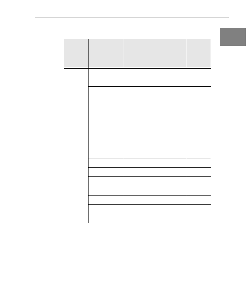
Table 1: Key Features Among the DT9800 Series
Analog
Input
Function
Series
DT9800
Standard
Series
DT9800EC
d
Series
DT9800EC-I
d
Series
a. The resolution is 12 bits.
b. The resolution is 16 bits.
c. The gains provided on the DT9805 and DT9806 are 1, 10, 100, and 500.
All other modules provide gains of 1, 2, 4, and 8.
d. The DT9800-EC Series boards are nonisolated; the DT9800-EC-I Series
boards and all other DT9800 Series boards are isolated.
e. The analog input range is 0 to 10 V or ±10 V.
Modules
DT9801
DT9802
DT9803
DT9804
DT9805
DT9806
DT9801-EC
DT9802-EC
DT9803-EC
DT9804-EC
DT9801-EC-Ia16 SE/8 DI
DT9802-EC-I
DT9803-EC-Ib16 SE/8 DI
DT9804-EC-I 16 SE/8 DI
a
a
b
b
c
c
a
a
b
b
a
# of
Analog Inputs
16 SE/8 DI 100 kS/s 0
16 SE/8 DI 100 kS/s 2
16 SE/8 DI 100 kS/s 0
16 SE/8 DI 100 kS/s 2
16 SE/8 DI/
7 thermocouples
and 1 CJC
16 SE/8 DI/
7 thermocouples
and 1 CJC
16 SE/8 DI
16 SE/8 DI
16 SE/8 DI
16 SE/8 DI
16 SE/8 DI
e
e
g
g
e
e
g
g
Sample
Rate
50 kS/s 0
50 kS/s 2
100 kS/s 0
100 kS/s 2
100 kS/s 0
100 kS/s 2
100 kS/s 0
100 kS/s 2
100 kS/s 0
100 kS/s 2
# of
Analog
Outputs
f
h
f
h
Overview
1
1
1
1
1
1
1
1
1
17
Page 18

Chapter 1
f. The analog output range is 0 to 10 V, 0 to 5 V, ±10 V, or ±5 V.
g. The analog input range is ±10 V.
h. The analog output range is ±10 V.
All DT9800 Series modules share the following major features:
• One 8-bit digital input port and one 8-bit digital output port; the
digital input lines can be included as part of the analog input
channel-gain list to correlate the timing of analog and digital
events; digital outputs can drive external solid-state relays
• Two 16-bit user counter/timers programmable for event
counting, frequency measurement, rate generation (continuous
pulse output), one-shot, and repetitive-one shot pulse output
operations
• USB compatibility
• Software configurable termination resistance for differential
inputs on a channel-by-channel basis
• Input gains of 1, 2, 4, and 8 for all modules except the DT9805 and
DT9806, which support gains of 1, 10, 100, and 500
18
• Continuously paced and triggered scan capability
• A 32-location channel-gain list that supports sampling analog
input channels at the same or different gains in sequential or
random order
• Internal and external clock sources for the analog input
subsystem
• Digital TTL triggering for the analog input subsystem
• One dynamic digital output line
• Programmable gate types and pulse output types
In addition, the DT9805 and DT9806 modules provide thermocouples
and low-level analog input capability. A software calibration utility is
provided for calibrating the analog I/O subsystems of all modules.
Page 19

Supported Software
The following software is available for use with the DT9800 Series
modules and is shipped on the Data Acquisition OMNI CD:
• DT9800 Series Device Driver – The device driver allows you to
use a DT9800 Series module with any of the supported software
packages or utilities. Refer to Chapter 3 for more information on
loading and configuring the device driver.
Overview
1
1
• Quick Data Acq application – The Quick Data Acq application
provides a quick way to get up and running using a DT9800
Series module. Using this application, you can verify key features
of the modules, display data on the screen, and save data to disk.
Refer to Chapter 6 for more information on using the Quick Data
Acq application.
• Calibration Utility – The Calibration Utility allows you to
calibrate the analog I/O circuitry of the modules. Refer to
Chapter 10 for more information on this utility.
• DT Measure Foundry – An evaluation version of this software is
included or provided via a link on the Data Acquisition OMNI
CD. DT Measure Foundry is drag-and-drop test and
measurement application builder designed to give you top
performance with ease-of-use development. Order the full
development version of this software package to develop your
own application using real hardware.
• DataAcq SDK – Use the Data Acq SDK if you want to develop
your own application software for the DT9800 Series modules
using the Microsoft C compiler; the DataAcq SDK complies with
the DT-Open Layers standard.
• DTx-EZ – DTx-EZ provides ActiveX controls, which allow you to
access the capabilities of the DT9800 Series boards using
Microsoft Visual Basic or Visual C++; DTx-EZ complies with the
DT-Open Layers standard.
1
1
1
1
1
1
1
19
Page 20

Chapter 1
• DAQ Adaptor for MATLAB – Data Translation’s DAQ Adaptor
provides an interface between the MATLAB Data Acquisition
(DAQ) subsystem from The MathWorks and Data Translation’s
DT-Open Layers architecture.
• DT-LV Link – Use DT-LV Link if you want to use the LabVIEW
graphical programming language to access the capabilities of the
DT9800 Series modules.
Refer to the Data Translation web site (www.datatranslation.com) for
information about selecting the right software package for your
needs.
Accessories
One EP310 cable is shipped with each DT9800 Series module. The
EP310 is a 2-meter, USB cable that connects the USB connector of the
DT9800 Series module to the USB connector on the host computer. If
you want to buy additional USB cables, EP310 is available as an
accessory product for the DT9800 Series.
20
In addition, you can purchase the following optional items from Data
Translation for use with the DT9800 Series:
• EP316 – A 5-meter, USB cable that connects the USB connector of
the DT9800 Series module to the USB connector on the host
computer.
• 5B01 – A 16-channel backplane that accepts 5B Series signal
conditioning modules.
• 5B08 – An 8-channel backplane that accepts 5B Series signal
conditioning modules.
• PWR-977 power supply – A 5 V, 3 A power supply for powering
the 5B Series backplanes.
• 7BP16-1 – A 16-channel backplane that accepts 7B Series signal
conditioning modules.
Page 21

• 7BP08-1 – An 8-channel backplane that accepts 7B Series signal
conditioning modules.
• 7BP04-1 – A 4-channel backplane that accepts 7B Series signal
conditioning modules.
Overview
1
• AC1324 – A screw terminal panel that connects to a DT9800-EC
or DT9800-EC-I Series module to allow access to the analog
I/O, dynamic digital output, counter/timer, and power signals.
• PB16H – A digital backplane that connects to the DT9800-EC or
DT9800-EC-I module to allow access to the digital I/O signals.
• STP-EZ – A screw terminal panel that connects to a DT9800-EC
or DT9800-EC-I Series module to allow access to the
digital I/O signals. A 50-pin ribbon cable is provided with the
STP-EZ to allow direct connection to a DT9800-EC or
DT9800-EC-I Series module.
• AC1315 – A 2-foot, 26-pin female to 26-pin female cable that
connects a 5B Series backplane to a DT9800-EC or DT9800-EC-I
Series module.
• AC1393 – A 6-inch, 26-pin male to 25-pin female adapter cable
that connects a 7B Series backplane to the AC1315 cable; the
AC1315 cable then connects to a DT9800-EC or DT9800-EC-I
Series module.
• HES14-21 power supply – A linear ac/dc power supply that
provides +24 Vdc for powering 7B Series backplanes.
• EP035 – A 2.4-meter, 50-pin ribbon cable that connects the PB16H
Opto 22 backplane to a DT9800-EC or DT9800-EC-I Series
module.
1
1
1
1
1
1
1
1
21
Page 22

Chapter 1
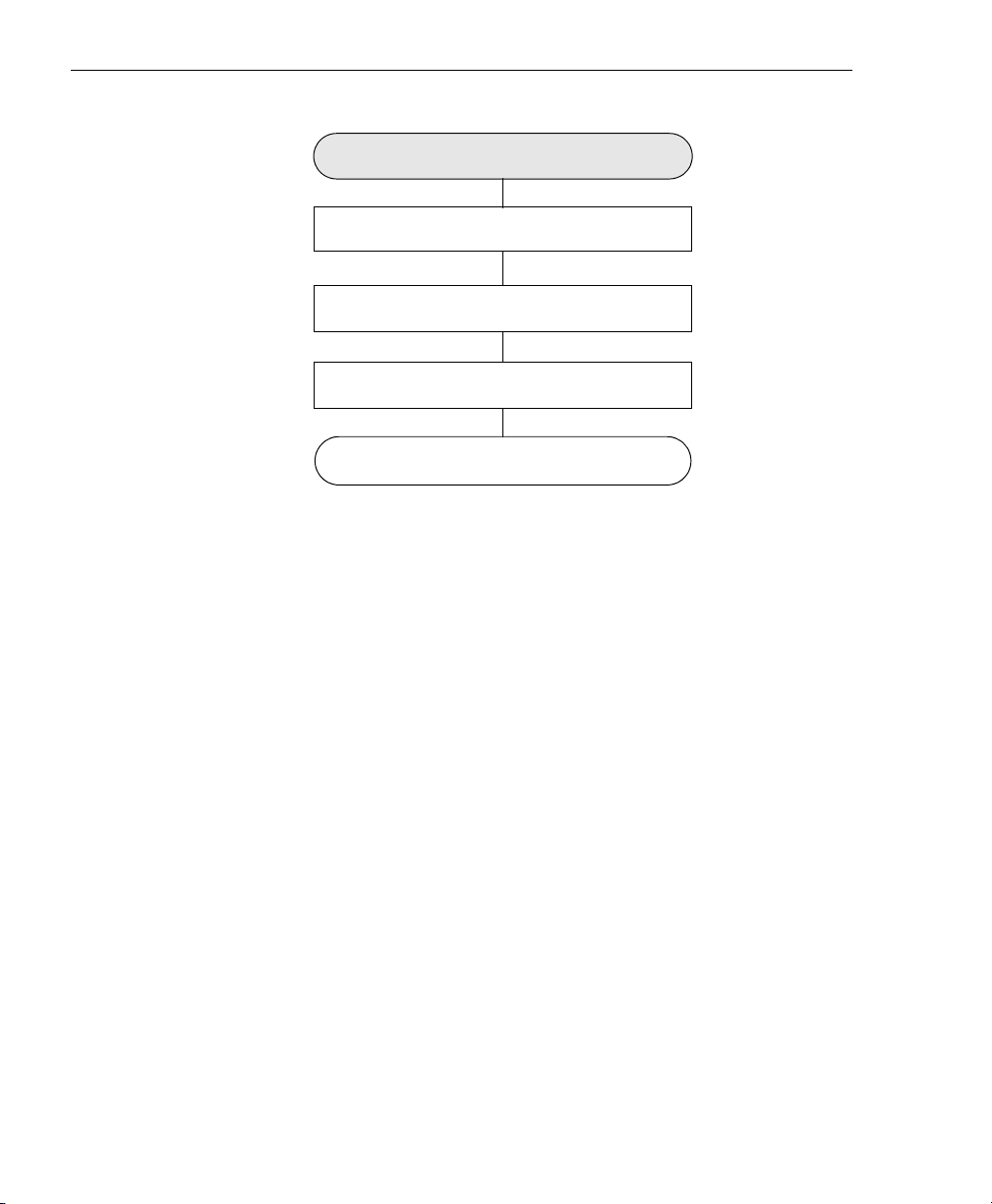
Getting Started Procedure
The flow diagram shown in Figure 1 illustrates the steps needed to
get started using the DT9800 Series modules. This diagram is
repeated in each Getting Started chapter; the shaded area in the
diagram shows you where you are in the procedure.
Preparing to Use a Module
(see Chapter 2 starting on page 25)
(see Chapter 3 starting on page 31)
Configure the Module and/or Device Driver
see Chapter 4 starting on page 43)
(see Chapter 5 starting on page 51)
Verify the Operation of the Module
(see Chapter 6 starting on page 105)
Install the Module
Wire Signals
Figure 1: Getting Started Flow Diagram
22
Page 23

Part 1: Getting Started
Page 24

Page 25

2
Preparing to Use a
Module
Unpacking . . . . . . . . . . . . . . . . . . . . . . . . . . . . . . . . . . . . . . . . . . . . . 27
Checking the System Requirements . . . . . . . . . . . . . . . . . . . . . . . 28
Installing the Software. . . . . . . . . . . . . . . . . . . . . . . . . . . . . . . . . . . 29
Viewing the Documentation Online . . . . . . . . . . . . . . . . . . . . . . . 30
25
Page 26
Chapter 2
Prepare to Use a Module
(this chapter)
Install the Module
(see Chapter 3 starting on page 31)
Configure the Module and/or Device Driver
see Chapter 4 starting on page 43)
Wire Signals
(see Chapter 5 starting on page 51)
Verify the Operation of the Module
(see Chapter 6 starting on page 105)
26
Page 27

Unpacking
Open the shipping box and verify that the following items are
present:
• DT9800 Series module
• EP310 USB cable
• Data Acquisition OMNI CD
Preparing to Use a Module
2
2
If an item is missing or damaged, contact Data Translation. If you are
in the United States, call the Customer Service Department at (508)
481-3700. An application engineer will guide you through the
appropriate steps for replacing missing or damaged items. If you are
located outside the United States, call your local distributor, listed on
Data Translation’s web site (www.datatranslation.com).
Once you have unpacked your module, check the system
requirements, as described in the next section.
2
2
2
2
2
2
2
27
Page 28

Chapter 2
Checking the System Requirements
For reliable operation, your DT9800 Series modules require the
following:
• PC with Pentium 233 MHz (or higher) processor.
• One or more USB ports (Ver. 1.1 or Ver. 2.0). USB Ver. 2.0 is not
required and will not improve performance for this module.
• Windows 2000 or Windows XP (Professional Edition) operating
system.
For USB Ver. 2.0 support, make sure that you install Service Pack
2 (for Windows XP) or Service Pack 4 (for Windows 2000). In
addition, for some systems, you may have to disable standby
mode. If you are not sure whether you are using USB Ver. 1.1 or
Ver. 2.0, run the Open Layers Control Panel applet, described on
page 45.
• 64 MB (or more) of RAM; 128 MB (or more) recommended.
• One or more CD-ROM drives.
28
• Super VGA (800 x 600 or higher resolution) display monitor.
Once you have verified that your system meets the system
requirements, install the software as described in the next section.
Page 29

Installing the Software
To install the software, do the following:
1. Insert the Data Acquisition OMNI CD into your CD-ROM drive.
Typically, the CD runs automatically. If the CD does not run
automatically, select Run from the Windows Start menu. Enter
x:\setup.exe (where x is the letter of your CD-ROM drive) in the Run
dialog box or use the Browse button to locate setup.exe, and then click
OK.
2. From the Data Acquisition Software setup program, click Install
Drivers.
A list of items that you are about to install appears.
3. Click Install now!
The DT-Open Layers Data Acquisition software wizard appears.
4. Click Next.
The installer prompts you for the destination location.
5. Either change the directory path and/or name using Browse or
accept the default directory (C\Program Files\Data Translation),
and then click Next.
The installer prompts you to begin file installation.
Preparing to Use a Module
2
2
2
2
2
2
6. Click Next.
The installer copies the files to the destination directory.
7. Click Finish.
The DT Data Acquisition Software setup program reappears.
8. Click Quit Installer.
2
2
2
29
Page 30

Chapter 2
Viewing the Documentation Online
Note: To view the documentation, you must have Adobe Acrobat
Reader 5.0 or greater installed on your system. Acrobat Reader is
provided on the Data Acquisition OMNI CD. If you install Acrobat
Reader from this CD, make sure that you open Acrobat Reader and
accept the license agreement before viewing the documentation.
You can access the DT9800 Series documentation from the Hardware
Documentation program group. From the Windows Start menu, click
Programs|Data Translation, Inc|Hardware Documentation, and
then select the appropriate document.
The following may be helpful when using Adobe Acrobat Reader:
• To navigate to a specific section of the document, click a heading
from the table of contents on the left side of the document.
• Within the document, click the text shown in blue to jump to the
appropriate reference (the pointer changes from a hand to an
index finger).
30
• To go back to the page from which the jump was made, click the
right mouse button and Go Back, or from the main menu, click
Document, and then Go Back.
• To print the document, from the main menu, click File, and then
Print.
• To increase or decrease the size of the displayed document, from
the main menu, click View, and then Zoom.
• By default, text and monochrome images are smoothed in
Acrobat Reader, resulting in blurry images. If you wish, you can
turn smoothing off by clicking File, and then
Preferences/General, and unchecking Smooth Text and Images.
Page 31

3
Installing a Module
Attaching Modules to the Computer. . . . . . . . . . . . . . . . . . . . . . . 17
Attaching Backplanes/Panels to the EC or EC-I Series . . . . . . . 37
31
Page 32

Chapter 3
Prepare to Use a Module
(see Chapter 2 starting on page 25)
Install the Module
(this chapter)
Configure the Device Driver and/or Module
(see Chapter 4 starting on page 43)
Wire Signals to the Module
(see Chapter 5 starting on page 51)
Verify the Operation of the Module
(see Chapter 6 starting on page 105)
32
Note: All DT9800 Series modules are factory-calibrated and require
no further adjustment prior to installation. If you are using the
DT9800 Standard, DT9800-EC, or DT9800-EC-I Series modules and
decide later to recalibrate them, refer to Chapter 10 for instructions.
Page 33

Attaching Modules to the Computer
You can attach a DT9800 Series module to the host computer in one of
two ways:
• Connect directly to a USB port of the host computer, described on
this page. Use this method if one or two DT9800 Series modules
are sufficient for your application.
• Connect to one or more self-powered USB hubs, described on
page 34. Use this method if your application requires more
DT9800 Series modules than the USB ports on the host computer.
You must install the device driver before connecting your DT9800
Series module(s) to the host computer. See “Installing the Software”
on page 29.
Installing a Module
3
3
3
3
Note: DT9800 Series modules are low-power devices (using less
than 500 mA); therefore, they do not require external power
supplies.
Connecting Directly to the USB Ports
To connect a DT9800 Series module directly to a USB port on your
computer, do the following:
1. Attach one end of the EP310 (USB) cable, which is shipped with
the DT9800 Series module, to the USB port on the module.
2. Attach the other end of the EP310 cable to one of the USB ports
on the host computer, as shown in Figure 2.
The operating system automatically detects the USB device and starts
the Found New Hardware wizard.
3
3
3
3
3
33
Page 34

Chapter 3
USB Ports
DT9800 Series
Modules
Host Computer
EP310 Cables
Figure 2: Attaching the Module to the Host Computer
3. Click Next and/or Finish in the wizard. Once the firmware is
loaded, the wizard restarts to initiate the firmware to accept
commands. Click Next and/or Finish again.
4. Repeat the steps to attach another DT9800 Series module to the
host computer, if desired.
Note: You can unplug a module, and then plug it in again, if you
wish, without causing damage. This process is called hot-swapping.
34
Your application may take a few seconds to recognize a module once
it is plugged back in.
Connecting to an Expansion Hub
Expansion hubs are powered by their own external power supply.
Theoretically, you can connect up to five expansion hubs to a USB
port on the host computer. However, the practical number of DT9800
Series modules that you can connect to a single USB port depends on
the throughput you want to achieve. Each of the hubs supports up to
four modules.
Page 35

Installing a Module
Note: The bandwidth of the USB Ver. 1.1 bus is 12 Mbits/second.
Each DT9800 Series module running at full speed (100 kHz) requires
200 kB of this bandwidth. Therefore, if you want to achieve full
throughput on each module, you should connect no more than four
DT9800 Series modules to a single USB Ver. 1.1 port.
To connect multiple DT9800 Series modules to an expansion hub, do
the following:
1. Attach one end of the USB cable to the DT9800 Series module and
the other end of the USB cable to an expansion hub.
2. Connect the power supply for the expansion hub to an external
power supply.
3. Connect the hub to the USB port on the host computer using
another USB cable.
The operating system automatically detects the USB device and starts
the Found New Hardware wizard.
4. Click Next and/or Finish in the wizard. Once the firmware is
loaded, the wizard restarts to initiate the firmware to accept
commands. Click Next and/or Finish again.
5. Repeat these steps until you have attached the number of hubs
(up to five) and modules (up to four per hub) that you desire.
Refer to Figure 3.
The operating system automatically detects the USB devices as they are
installed.
3
3
3
3
3
3
3
3
3
35
Page 36

Chapter 3
Host Computer
USB Cable
DT9800 Series
Module
USB Cables
DT9800 Series
Module
USB Cable
Power Supply
for Hub
DT9800 Series
Module
USB Cables
Self-Powered
USB Hubs
DT9800 Series
Module
Figure 3: Attaching Multiple Modules Using Expansion Hubs
Note: You can unplug a module, and then plug it in again, if you
wish, without causing damage. This process is called hot-swapping.
Your application may take a few seconds to recognize a module once
it is plugged back in.
If you are using a DT9800-EC or DT9800-EC-I Series module,
continue with the next section. Otherwise, continue with the
instructions on wiring in Chapter 4 starting on page 43.
36
Page 37

Installing a Module
Attaching Backplanes/Panels to the EC or EC-I Series
Only the DT9800-EC and DT9800-EC-I Series modules support
Analog Devices 5B and 7B Series backplanes, the Opto-22 PB16H
digital I/O backplane, and the Data Translation STP-EZ backplane
and AC1324 screw terminal panel.
The DT9800-EC and DT9800-EC-I Series modules provide the
following three connectors:
• Connector J6 − Supports 5B and 7B Series backplanes or an
AC1324 screw terminal panel for analog input connections.
3
3
3
Specific 5B and 7B Series backplanes that are supported include
the following:
− 5B01 − a 16-channel backplane for 5B Series signal
conditioning modules
− 5B08 − an 8-channel backplane for 5B Series signal
conditioning modules
− 7BP16-1 − a 16-channel backplane for 7B Series signal
conditioning modules
− 7BP08-1 − an 8-channel backplane for 7B Series signal
conditioning modules
− 7BP04-1 − a 4-channel backplane for 7B Series signal
conditioning modules
• Connector J5 − Supports an AC1324 screw terminal panel for
analog output, dynamic digital output, counter/timer, and
power connections.
• Connector J4 − Supports the STP-EZ and the PB16H digital I/O
backplane. The PB16H supports eight digital inputs at locations 0
to 7, and eight digital outputs at locations 8 to 15.
3
3
3
3
3
3
37
Page 38

Chapter 3
Figure 4 shows the location of these connectors on the DT9800-EC
and DT9800-EC-I Series modules.
DT9800-EC or DT9800-EC-I
Series Module
J5
J6
J4
Figure 4: J6, J5, and J4 Connectors
38
This section describes how to connect a 5B or 7B Series backplane, a
AC1324 screw terminal panel, and/or a PB16H Opto-22 backplane to
your DT9800-EC or DT9800-EC-I Series module.
Page 39

Attaching a 5B Series Backplane
Installing a Module
To connect a 5B Series signal conditioning backplane to a DT9800-EC
or DT9800-EC-I Series module, complete the steps that follow while
referring to Figure 5:
USB Cable to
Host Computer
Figure 5: Connecting a 5B Series Backplane to the DT9800-EC or
DT9800-EC/
DT9800-EC-I
DT9800-EC-I Series Modules
J6 Connector
5B Series Backplane
AC1315
Cable
PWR-977
Power Supply
To wall outlet
3
3
3
3
3
3
1. Plug one end of an AC1315 cable into the J6 connector of the
DT9800-EC or DT9800-EC-I Series module.
2. Plug the other end of the AC1315 cable into the 26-pin connector
on the 5B Series backplane.
3. Connect power supply PWR-977 to the +5 V and power ground
screw terminals on the 5B Series backplane and to the wall outlet.
3
3
3
39
Page 40

Chapter 3
Attaching a 7B Series Backplane
To connect a 7B Series signal conditioning backplane to a DT9800-EC
or DT9800-EC-I Series module, complete the steps that follow while
referring to Figure 6:
AC1393
Adapter Cable
7B Series Backplane
HES14-21
Power Supply
USB Cable to
Host Computer
J6 Connector
DT9800-EC/
DT9800-EC-I
AC1315
Cable
To wall outlet
Figure 6: Connecting a 7B Series Backplane to the DT9800-EC or
DT9800-EC-I Series Modules
1. Plug one end of an AC1315 cable into the J6 connector of the
DT9800-EC or DT9800-EC-I Series module.
2. Plug the other end of the AC1315 cable into the 26-pin connector
of the AC1393 adapter cable; then, attach the 25-pin connector of
the AC1393 adapter cable to the 7B Series backplane.
3. Connect power supply HES14-21 to the V+A and COM screw
terminals on the 7B Series backplane and to the wall outlet.
40
Page 41

Attaching an AC1324 Screw Terminal Panel
Installing a Module
To connect an AC1324 screw terminal panel to a DT9800-EC or
DT9800-EC-I Series module, do the following:
1. Plug one end of an AC1315 cable into the J6 or J5 connector of the
DT9800-EC or DT9800-EC-I Series module.
2. Plug the other end of the AC1315 cable into the 26-pin connector
on the AC1324 screw terminal panel, as shown in Figure 7.
J6 or J5 Connector
USB Cable to
Host Computer
Figure 7: Connecting the AC1324 Screw Terminal Panel to the
DT9800-EC or DT9800-EC-I Series Module
DT9800-EC/
DT9800-EC-I
AC1315
Cable
Attaching a PB16H Opto-22 Backplane
3
3
3
3
AC1324
3
3
To connect a PB16H Opto-22 backplane to a DT9800-EC or
DT9800-EC-I Series module, do the following:
1. Plug one end of an EP035 cable into the J4 connector of the
DT9800-EC or DT9800-EC-I Series module.
2. Plug the other end of the EP035 cable into the 50-pin connector on
the PB16H Opto-22 backplane, as shown in Figure 8.
3
3
3
41
Page 42

Chapter 3
USB Cable
to Host
Computer
DT9800-EC/
DT9800-EC-I
J4 Connector
PB16H Opto-22 Backplane
EP035 50-Pin
Ribbon Cable
Figure 8: Connecting the PB16H Opto-22 Backplane to the
DT9800-EC or DT9800-EC-I Series Module
Attaching an STP-EZ Screw Terminal Panel
To connect an STP-EZ screw terminal panel to a DT9800-EC or
DT9800-EC-I Series module, do the following:
1. Attach one end of the 50-pin cable that is shipped with the
STP-EZ screw terminal panel into connector J4 on the DT9800-EC
or DT9800-EC-I board.
2. Attach the other end of the cable to the J1 connector on the
STP-EZ screw terminal panel, as shown in Figure 9.
42
USB Cable
to Host
Computer
DT9800-EC/
DT9800-EC-I
J4 Connector
50-Pin Ribbon
Cable
STP-EZ
J1 Connector
Figure 9: Connecting the STP-EZ to the DT9800-EC or
DT9800-EC-I Module
Page 43

4
Configuring the Module and/or
Device Driver
Configuring the DT9800 Series Device Driver. . . . . . . . . . . . . . . 45
Configuring the EC and EC-I Series Modules . . . . . . . . . . . . . . . 47
43
Page 44

Chapter 4
Prepare to Use a Module
(see Chapter 2 starting on page 25)
(see Chapter 3 starting on page 31)
Configure the Module and/or Device Driver
(see Chapter 5 starting on page 51)
Verify the Operation of the Module
(see Chapter 6 starting on page 105)
Install the Module
this chapter)
Wire Signals
If you are using a DT9800 Standard Series, DT9800-EC Series, or
DT9800-EC-I Series module, you must configure the device driver;
refer to page 45 for information.
In addition, if you are using a DT9800-EC or DT9800EC-I Series
module, you must configure the module; refer to page 47 for
information.
44
Page 45

Configuring the Module and/or Device Driver
Configuring the DT9800 Series Device Driver
This section describes how to configure the device driver for a
DT9800 Standard Series, DT9800-EC Series, or DT9800-EC-I Series
module to use or not use bias-return termination resistance.
To configure the device driver, do the following:
1. If you have not already done so, power up the host computer and
all peripherals.
2. From the Windows Control Panel, double-click the Open Layers
Control Panel icon.
The Data Acquisition Control Panel dialog box appears.
3. Click the DT9800 Series module that you want to configure, and
then click Advanced.
The DT9800 Configuration dialog box appears.
4. If you are using differential analog input channels, we
recommend that you select the 10k Ohm Resistor Terminations
checkbox for each analog input channel on the module. This
ensures that 10 kΩ of bias return termination resistance is used
for the analog input channels. (This is the default configuration.)
Bias return termination resistance is particularly useful when
your differential source is floating.
4
4
4
4
4
4
If you are using single-ended analog input channels, clear the
checkbox for each analog input channel so that bias return
resistance is not used.
4
4
4
45
Page 46

Chapter 4
5. To continuously power the analog and/or digital outputs, select
the Power Always On checkbox. The DT9800 Series module will
remain on even when you exit from the applications that use the
module.
If you want to shut down power to the module, you must
uncheck this checkbox and close the control panel. Once all
applications that use this module are exited, the module will
power down. The module will remain off until you either run an
application that uses the module or click the Advanced button
from the Open Layers Data Acquisition Control Panel.
6. Click OK.
7. If you want to rename the module, click Edit Name; otherwise,
go to step 9.
8. Enter a new name for the module, and then click OK.
Note: This name is used to identify the module in all subsequent
applications.
46
9. When you are finished configuring the module, click Close.
10. Repeat steps 3 to 9 for the other modules that you want to
configure.
11. Close the Control Panel.
If you are using a DT9800-EC or DT9800-EC-I module, continue with
the next section. Otherwise, continue with the instructions on wiring
in Chapter 5 starting on page 51.
Page 47

Configuring the Module and/or Device Driver
Configuring the EC and EC-I Series Modules
To use 5B or 7B Series signal conditioning backplanes with a
DT9800-EC or DT9800-EC-I Series module, you must configure your
USB module for proper operation.
By default, the 5B01 and 7BP16-1 backplanes map to single-ended
analog input channels 0 to 15, the 5B08 and 7BP08-1 backplanes map
to single-ended analog input channels 0 to 7, and the 7BP04-1
backplane maps to single-ended analog input channels 0 to 3.
However, you can use channels 14 and 15 on the 5B01 or 7BP16-1
backplane as analog output channels 0 and 1, if you wish.
Note: You cannot use analog output modules on the 5B08, 7BP04-1,
or 7BP08-1 backplane.
4
4
4
4
4
You can determine how channels 14 and 15 are used on the 5B01 and
7BP16-1 backplanes using DIP switch block SW1 on the DT9800-EC
and DT9800-EC-I modules. DIP switch SW1 contains switches 1 to 4.
To use channels 14 and 15 on the 5B01 or 7BP16 as analog inputs,
slide all the switches of DIP switch SW1 on the DT9800-EC or
DT9800-EC-I Series module to the OFF position. To use channel 14 on
the 5B01 or 7BP16 as analog output channel 0, set switches 1 and 3 of
DIP switch SW1 on the DT9800-EC or DT9800-EC-I Series module to
the ON position.
To use channel 15 on the 5B01 or 7BP16 as analog output channel 1,
set switches 2 and 4 of DIP switch SW1 on the DT9800-EC or
DT9800-EC-I Series modules to the ON position.
Refer to Figure 10 for the location of DIP switch SW1.
4
4
4
4
47
Page 48

Chapter 4
SW1
J6
SW1
OFF
1
2
3
4
J5
J4
ON
DT9800-EC or DT9800-EC-I
Series Module
Figure 10: DIP Switch SW1
Function
Channel 14 is an
Analog Input
Channel 15 is an
Analog Input
Channel 14 is an
Analog Output
Channel 15 is an
Analog Output
Switch Settings
Set switches 1 and
3 of SW1 OFF.
Set switches 2 and
4 of SW1 OFF.
Set switches 1 and
3 of SW1 ON.
Set switches 2 and
4 of SW1 ON.
48
For example, assume that you are using a 5B01 with the DT9801-EC
and that you want to use analog output channels 0 and 1. In this case,
ensure that you wire DAC0 signals to channel 14 and DAC1 signals
to channel 15 on the 5B01 backplane. Then, set all the switches of DIP
switch SW1 on the DT9800-EC or DT9800-EC-I Series module to the
ON position.
Page 49

Configuring the Module and/or Device Driver
Also note the following considerations when using 5B and 7B Series
signal conditioning accessories:
• If you are using a 5B Series backplane, you must install jumper
W3 on the 5B Series backplane to connect Amp Low to Analog
Ground.
• 5B and 7B thermocouple modules provide their own CJC and
return a voltage that already compensates for CJC. Therefore,
when using 5B and 7B Series thermocouple modules, you do not
have to compensate for offsets.
• The output of many 5B modules is ±5 V. The output of many 7B
modules is 0 to 10 V. Ensure that you select an input range that
matches the output of the 5B or 7B modules that you are using.
For example, if you are using 5B modules that have an output of
±5 V, use a bipolar input range and a gain of 2 on the DT9800-EC
and DT9800-EC-I Series modules.
• Connect all unused inputs to analog common. Reading an open
channel can cause settling problems on the next valid channel.
4
4
4
4
4
4
4
4
4
49
Page 50

Chapter 4
50
Page 51

5
Wiring Signals
Wiring Signals to a DT9800 Standard Series Module . . . . . . . . . 53
Wiring Signals to the EC or EC-I Series. . . . . . . . . . . . . . . . . . . . . 74
51
Page 52

Chapter 5
Prepare to Use a Module
(see Chapter 2 starting on page 25)
Install the Module
(see Chapter 3 starting on page 31)
Configure the Module and/or Device Driver
see Chapter 4 starting on page 43)
Wire Signals
(this chapter)
Verify the Operation of the Module
(see Chapter 6 starting on page 105)
Note: For information about the special DT9804 BNC modules,
refer to “DT9804 BNC Modules,” in Appendix B.
52
Page 53

Wiring Signals to a DT9800 Standard Series Module
Wiring Signals
5
CAUTION:
To avoid electrostatic sensitivity, unplug your DT9800 Series module
from the computer before wiring signals.
Keep the following recommendations in mind when wiring signals to
a DT9800 Standard Series module:
• Use individually shielded twisted-pair wire (size 14 to 26 AWG)
when using the DT9800 Standard Series module in highly noisy
electrical environments.
• Separate power and signal lines by using physically different
wiring paths or conduits.
• To avoid noise, do not locate the DT9800 Standard Series module
and cabling next to sources that produce high electromagnetic
fields, such as large electric motors, power lines, solenoids, and
electric arcs, unless the signals are enclosed in a mumetal shield.
• Prevent electrostatic discharge to the I/O while the module is
operational.
• Connect all unused analog input channels to analog ground.
• When first installing the module, try wiring the signals as
follows:
5
5
5
5
5
5
− Wire a function generator or a known voltage source to
analog input channel 0 using the differential configuration.
− Wire an oscilloscope or voltage meter to analog output
channel 0.
− Wire a digital input to digital input line 0 of port A.
− Wire a digital output to digital output line 0 of port B.
5
5
53
Page 54

Chapter 5
− Wire an external clock or scope to counter/timer channel 0.
− Then, run the Quick Data Acq application (described in
Chapter 6 starting on page 105) to verify that the module is
operating properly.
Once you have determined that the module is operating
properly, wire the signals according to your application’s
requirements.
Figure 11 shows the assignments of the screw terminals on DT9800
Standard Series modules. The screw terminal blocks are removable
for your convenience.
54
Page 55

t
t
t
t
User Clk Input 0
User Cntr Out 0
External Gate 0
Isolated Dig Gnd
User Clk Input 1
User Cntr Out 1
External Gate 1
Isolated Dig Gnd
Dynamic Dig Out
Digital Output 0
Digital Output 1
Digital Output 2
Digital Output 3
Digital Output 4
Digital Output 5
Digital Output 6
Digital Output 7
Isolated Dig Gnd
54
53
52
51
50
49
48
47
46
45
44
43
42
41
40
39
38
37
36
Isolated Dig Gnd
35
Digital Input 7
DT9800 Standard Series Modules
27
29
30
31
32
33
34
Digital Input 6
Digital Input 5
Digital Input 4
Digital Input 3
Digital Input 2
Digital Input 1
28
Digital Input 0
Isolated +5 V Out
Isolated Dig Gnd
26
24
25
Ext A/D Sample Clk
Ext A/D Trigger
23
Isolated Dig Gnd
22
Analog Out 1 Ret
1
2
3
4
5
6
7
8
9
10
11
12
13
14
15
16
17
18
20
21
Analog Out 1+
Analog Out 0 Ret
Channel 00
Channel 08/00 Ret
Channel 01
Channel 09/01 Ret
Channel 02
Channel 10/02 Ret
Channel 03
Channel 11/03 Ret
Channel 04
Channel 12/04 Re
Channel 05
Channel 13/05 Re
Channel 06
Channel 14/06 Re
Channel 07
Channel 15/07 Re
Isolated An Gnd
Amp Low
19
Analog Out 0+
Wiring Signals
5
5
5
5
5
Figure 11: DT9800 Standard Series
Screw Terminal Assignments
Note: Screw terminals TB19 through TB22 are not used on DT9801,
DT9803, and DT9805 modules since these modules do not support
analog output.
5
5
5
5
55
Page 56

Chapter 5
Connecting Analog Input Signals
DT9800 Standard Series modules support both voltage and current
loop inputs.
You can connect analog input signals to a DT9800 Standard Series
module in the following configurations:
• Single-ended − Choose this configuration when you want to
measure high-level signals, noise is not significant, the source of
the input is close to the module, and all the input signals are
referred to the same common ground. When you choose the
single-ended configuration, all 16 analog input channels are
available on the DT9800 Standard Series.
• Pseudo-Differential − Choose this configuration when noise or
common-mode voltage (the difference between the ground
potentials of the signal source and the ground of the module or
between the grounds of other signals) exists and the differential
configuration is not suitable for your application. This option
provides less noise rejection than the differential configuration;
however, all 16 analog input channels are available on the
DT9800 Standard Series.
56
• Differential − Choose this configuration when you want to
measure thermocouple or low-level signals (less than 1 V), you
are using an A/D converter with high resolution (greater than
12 bits), noise is a significant part of the signal, or common-mode
voltage exists. When you choose the differential configuration,
eight analog input channels are available on the DT9800
Standard Series.
This section describes how to connect single-ended,
pseudo-differential, and differential voltage inputs, as well as current
loop and thermocouple inputs to the DT9800 Standard Series
module.
Page 57

Connecting Single-Ended Voltage Inputs
Wiring Signals
Figure 12 shows how to connect single-ended voltage inputs
(channels 0, 1, and 8, in this case) to a DT9800 Standard Series
module.
Note: If you are using single-ended inputs, set up the software so
that bias return resistance is not used. For more information, refer to
page 45.
Signal
Source
V
-
Vsource 8
-
Vsource 1
source 0
+
+
+
Analog In 0
Analog In 8
Analog In 1
DT9800 Standard Series
Module
TB1
TB2
TB3
5
5
5
5
5
5
*Ensure that you
Isolated Analog Ground*
TB18*
Figure 12: Connecting Single-Ended Voltage Inputs
(Shown for Channels 0, 1, and 8)
TB17
connect Isolated Analog
Ground to Amp Low.
5
5
5
57
Page 58

Chapter 5
Connecting Pseudo-Differential Voltage Inputs
Figure 13 shows how to connect pseudo-differential voltage inputs
(channels 0, 1, and 8, in this case) to a DT9800 Standard Series
module.
Signal
Source
V
-
Vsource 8
-
*
V
CM
Vsource 1
*Make this connection as close to V
possible to reduce ground loop errors. V
common mode voltage for all 16 analog inputs.
+
source 0
+
+
Isolated Analog Ground
Amp Low
Analog In 0
Analog In 8
Analog In 1
DT9800 Standard Series
Module
TB1
TB2
TB3
TB17
TB18
sources as
IN
is the
cm
58
Figure 13: Connecting Pseudo-Differential Voltage Inputs
(Shown for Channels 0, 1, and 8)
Page 59

Wiring Signals
Note: If you are using pseudo-differential inputs, set up the
software so that bias return resistance is not used. For more
information, refer to page 45.
Connecting Differential Voltage Inputs
Figure 14A illustrates how to connect a floating signal source to a
DT9800 Standard Series module using differential inputs. (A floating
signal source is a voltage source that has no connection with earth
ground.)
Note: For floating signal sources, we recommend that you provide
a bias return path for the differential channels by adding 10 kΩ of
termination resistance from the low side of the channel to isolated
analog ground.
For more information on configuring termination resistance, refer to
page 45.
5
5
5
5
5
5
Figure 14B illustrates how to connect a nonfloating signal source to a
DT9800 Series module using differential inputs. In this case, the
signal source itself provides the bias return path; therefore, you do
not need to provide bias return resistance through software.
R
is the signal source resistance while Rv is the resistance required to
s
balance the bridge. Note that the negative side of the bridge supply
must be returned to analog ground.
5
5
5
59
Page 60

Chapter 5
A)
Floating
Signal
Source
B)
R
v
R
s
R
s
Bridge
+
Analog In 0
Analog In 0
Return
-
Isolated Analog
Ground
DT9800 Standard Series
Module
Analog In 0
Analog In 0
Return
.
.
.
TB1
TB2
TB17
We recommend that you
software-select 10 k
resistance to connect
the low side of channel 0
to analog ground (a
physical resistor is not
required). Refer to page
TB1
45 for more information.
TB2
Ω of
60
+
DC Supply
-
.
Isolated
Analog Ground
.
.
TB17
Figure 14: Connecting Differential Voltage Inputs (Shown for Channel 0)
Page 61

Wiring Signals
Note that since they measure the difference between the signals at the
high (+) and low (−) inputs, differential connections usually cancel
any common-mode voltages, leaving only the signal. However, if you
are using a grounded signal source and ground loop problems arise,
connect the differential signals to the DT9800 Standard Series module
as shown in Figure 15. In this case, make sure that the low side of the
signal (−) is connected to ground at the signal source, not at the
DT9800 Standard Series module, and do not tie the two grounds
together.
DT9800 Standard Series
Module
5
5
5
.
.
.
TB1
TB2
TB17
We recommend that you
software-select 10 k
resistance to connect
the low side of channel 0
to analog ground (a
physical resistor is not
required). Refer to
Chapter 4 for more
information.
+
Analog In 0
Grounded
Signal
Source
Signal Source
Ground V
Figure 15: Connecting Differential Voltage Inputs from a Grounded Signal
E
s
-
g1
Analog In 0
Return
Isolated Analog
Ground
Source (Shown for Channel 0)
5
5
Ω of
5
5
5
5
61
Page 62

Chapter 5
Connecting Current Loop Inputs
Figure 16 shows how to connect a current loop input (channel 0, in
this case) to a DT9800 Standard Series module.
+V
CC
4 to 20 mA
Analog Input 0
Analog Input 0
Return
Isolated Analog
Ground
DT9800 Standard Series
Module
TB1
TB2
.
.
.
TB17
We recommend that you software-select 10 k
termination resistance to connect the low side of
channel 0 to analog ground (a physical resistor is
not required). Refer to page 45 for more
information.
User-installed resistor
The user-installed
resistor connects the high
side of the channel to the
low side of the
corresponding channel,
thereby acting as a shunt.
If, for example, you add a
250
Ω resistor, then
connect a 4 to 20 mA
current loop input to
channel 0, the input range
is converted to 1 to 5 V.
Figure 16: Connecting Current Inputs (Shown for Channel 0)
Ω of
62
Page 63

Wiring Signals
Note: If you are using current loop inputs, set up the software so
that bias return resistance is used. For more information, refer to
page 45.
Connecting Thermocouple Inputs
The DT9805 and DT9806 modules provide cold junction
compensation (CJC) on channel 0 at 10 mV/
seven thermocouples to the DT9805 or DT9806 module using channel
0 as a CJC. The accuracy of the CJC is ±1
Figure 17 shows how to connect a thermocouple input to channel 1 of
a DT9805 or DT9806 module.
° C. You can attach up to
° from 5° to 45° C.
5
5
5
5
5
5
5
5
5
63
Page 64

Chapter 5
.
No Connection
to Channel 0
+
-
DT9805 or DT9806 Module
CJC
10 mV/
High
Low
High
Low
TB2
TB1
TB3
TB4
10 kΩ
10 kΩ∗
10 kΩ∗
10 M
° C
+2.5 V Ref
Ω
MUX
Chan 0
Chan 1
Thermocouple
Input on
Channel 1
Isolated Analog
Ground
.
.
.
TB17
*We recommend that you software-select 10 kΩ of
termination resistance to connect the low side of
channels 0 and 1 to analog ground (a physical resistor
is not required). Refer to page 45 for more information
The 10 kΩ resistor to the CJC, the CJC,
the 10 M
reference are supplied on the DT9805
and DT9806 module.
Due to the 10 M
reference, the output of the channel
goes to full scale if an open circuit is
detected at the input.
Ω resistor, and the +2.5 V
Ω resistor to the +2.5 V
Figure 17: Connecting Thermocouple Inputs (Shown for Channel 1)
Note: You can connect voltages instead of thermocouples to the
DT9805 and DT9806 modules. In this case, ensure that the signal you
attach to channel 0 is capable of driving 10 kΩ, and that the signals
you attach to channels 1, 2, 3, 4, 5, 6, and 7 are capable of driving
10 MΩ.
64
Page 65

Connecting Analog Output Signals
Wiring Signals
Figure 18 shows how to connect an analog output voltage signal
(channel 0, in this case) to a DT9802, DT9804, or DT9806 module.
Analog Output 0
Load
Figure 18: Connecting Analog Output Voltages (Shown for Channel 0)
Connecting Digital I/O Signals
Figure 19 shows how to connect digital input signals (lines 0 and 1,
Port A, in this case) to a DT9800 Standard Series module.
Analog Output 0 Return
DT9802, DT9804, or DT9806
Module
TB19
TB20
5
5
5
5
5
5
5
5
5
65
Page 66

Chapter 5
DT9800 Standard
Series Module
TTL Inputs
Digital Input Line 0 (Port A)
Digital Input Line 1 (Port A)
Isolated Digital Ground
TB28
TB29
TB36
Figure 19: Connecting Digital Inputs (Shown for Lines 0 and 1, Port A)
Figure 20 shows how to connect a digital output (line 0, Port B, in this
case) to a DT9800 Standard Series module.
DT9800 Standard
Series Module
0 Out = LED On
TB45
500 Ω
+
5 V
-
Digital Output Line 0 (Port B)
66
Isolated Digital Ground
TB37
Figure 20: Connecting Digital Outputs (Shown for Line 0, Port B)
Page 67

Connecting Counter/Timer Signals
Wiring Signals
DT9800 Standard Series modules provide two user counter/timer
channels that you can use for the following operations:
• Event counting
• Frequency measurement
• Pulse output (rate generation, one-shot, and repetitive one-shot)
This section describes how to connect counter/timer signals to
perform these operations. Refer to Chapter 7 for more information on
using the counter/timers.
Connecting Event Counting Signals
Figure 21 shows one example of connecting event counting signals to
a DT9800 Standard Series module using user counter 0. In this
example, rising clock edges are counted while the gate is active.
User Clock Input 0
Signal Source
External
Gating
Switch
Gate 0
Isolated Digital
Ground
TB54
TB52
TB51
5
5
5
5
5
5
5
Isolated Digital Ground
Figure 21: Connecting Event Counting Signals
(Shown for Clock Input 0 and External Gate 0)
TB47
DT9800 Standard
Series Module
5
5
67
Page 68

Chapter 5
Figure 22 shows another example of connecting event counting
signals to a DT9800 Standard Series module using user counter 0. In
this example, a software gate is used to start the event counting
operation; however, this connection is not required.
DT9800 Standard
Series Module
Signal Source
User Clock Input 0
Isolated Digital
Ground
TB54
TB51
Figure 22: Connecting Event Counting Signals without an External Gate
Input (Shown for Clock Input 0)
Figure 23 shows an example of how to cascade two counters
externally to perform an event counting operation using user
counters 0 and 1. Note that you can also internally cascade counters
using software; if you internally cascade the counters, you do not
need to make the external cascading connections.
68
Page 69

Wiring Signals
User Clock Input 0
Signal
Source
Figure 23: Cascading Counters (Shown for Event Counting Using
External
Gating
Switch
Counters 0 and 1 and External Gate 0)
Gate 0
Isolated Digital
Ground
Gate 1
Isolated Digital Ground
TB53
TB50
DT9800 Standard
Series Module
Connecting Frequency Measurement Signals
This section describes two examples of how to connect frequency
measurement signals to a DT9800 Standard Series module.
TB54
TB52
TB51
TB48
TB47
User
Counter
Output 0
User Clock
Input 1
5
5
5
5
5
5
The first configuration uses the same wiring as an event counting
application that does not use an external gate signal (see Figure 22 on
page 68); a system timer specifies the duration of the frequency
measurement. In this configuration, the frequency of the clock input
is the number of counts divided by the duration of the Windows
timer.
5
5
5
69
Page 70

Chapter 5
If you need more accuracy than the system timer provides, you can
connect a pulse of a known duration (such as a one-shot output of
another user counter) to the external gate input, as shown in Figure
24. In this configuration, the frequency of the clock input is the
number of counts divided by the period of the external gate input.
DT9800 Standard
Series Module
Signal Source
Figure 24: Connecting Frequency Measurement Signals
User Clock Input 0
Gate 0
Isolated Digital Ground
(Shown for Clock Input 0 and External Gate 0)
TB54
TB52
TB49
TB47
User
Counter
Output 1
70
Page 71

Connecting Pulse Output Signals
Wiring Signals
Figure 25 shows one example of connecting pulse output signals to a
DT9800 Standard Series module using user counter 0.
User Clock Output 0
Heater
controller
Figure 25: Connecting Pulse Output Signals
(Shown for Counter Output 0 and Gate 0)
Figure 26 shows an example of how to externally cascade two
counters to perform a rate generation operation using user counters 0
and 1. Note that you can also cascade counters internally using
software; if you internally cascade the counters, you do not need to
make the external cascading connections. In this example, counter 1
gate is logic high.
External
Gating
Switch
Isolated Digital Ground
Gate 0
Isolated Digital
Ground
DT9800 Standard
Series Module
TB53
TB52
TB51
TB47
5
5
5
5
5
5
5
5
5
71
Page 72

Chapter 5
User Clock Input 0
Signal
Source
External
Gating
Switch
Gate 0
Isolated Digital
Ground
Isolated Digital Ground
TB53
TB50
DT9800 Standard
Series Module
Figure 26: Cascading Counters (Shown for Rate Generation Using
Counters 0 and 1 and External Gate 0)
Figure 27 shows an example of how to cascade two counters
externally to perform a one-shot operation using user counters 0 and
1. Note that you can also internally cascade counters using software;
if you internally cascade the counters, you do not need to make the
external cascading connections. In this example, counter 0 gate is
logic high.
TB54
TB52
TB51
TB47
User
Counter
Output 0
User Clock
Input 1
72
Page 73

Wiring Signals
User Clock Input 0
Signal
Source
One-Shot
Tri gger
Figure 27: Cascading Counters (Shown for One-Shot Using
Counters 0 and 1 and External Gate 1)
Isolated Digital
Ground
Gate 1
Isolated Digital Ground
TB53
TB50
DT9800 Standard
Series Module
TB54
TB51
TB48
TB47
User
Counter
Output 0
User Clock
Input 1
5
5
5
5
5
5
5
5
5
73
Page 74

Chapter 5
Wiring Signals to the EC or EC-I Series
CAUTION:
To avoid electrostatic sensitivity, it is recommended that you unplug
your DT9800 Series module from the computer before wiring signals.
When first installing the module, try wiring the signals as follows:
• Wire a function generator or a known voltage source to analog
input channel 0 using the differential configuration.
• Wire an oscilloscope or voltage meter to analog output channel 0.
• Wire a digital input to digital input Port A.
• Wire an external clock or scope to counter/timer channel 0.
• When you finish wiring the signals, run the Quick Data Acq
application (described in Chapter 6 starting on page 105) to verify
that the module is operating properly.
Once you have determined that the module is operating
properly, wire the signals according to your application’s
requirements.
74
Tabl e 2 lists the pin assignments for connector J6, Tab le 3 lists the pin
assignments for connector J5, and Table 4 lists the pin assignments
for connector J4 on the DT9800-EC and DT9800-EC-I Series modules.
Page 75

Wiring Signals
Table 2: Connector J6 Pin Assignments
AC1324
a
Screw
Terminal
a
Signal Name
J6
Pin #
J6
Pin #
1 TB1 Analog Input 0 2 TB2 Analog Input 0 Return/
a
AC1324
Screw
Terminal
a
Signal Name
Analog Input 8
5
5
3 TB3 Isolated Analog
Ground
5 TB5 Analog Input 1 6 TB6 Isolated Analog
7 TB7 Analog Input 2 8 TB8 Analog Input 2 Return/
9 TB9 Isolated Analog
Ground
11 TB11 Analog Input 3 12 TB12 Isolated Analog
13 TB13 Analog Input 4 14 TB14 Analog Input 4 Return/
15 TB15 Isolated Analog
Ground
17 TB17 Analog Input 5 18 TB18 Isolated Analog
19 TB19 Analog Input 6 20 TB20 Analog Input 6 Return/
21 TB21 Not Connected 22 TB22 Analog Input 7 Return/
b
b
b
4 TB4 Analog Input 1 Return/
Analog Input 9
b
Ground
Analog Input 10
10 TB10 Analog Input 3 Return/
Analog Input 11
b
Ground
Analog Input 12
16 TB16 Analog Input 5 Return/
Analog Input 13
b
Ground
Analog Input 14
Analog Input 15
5
5
5
5
5
5
5
75
Page 76

Chapter 5
Table 2: Connector J6 Pin Assignments (cont.)
J6
Pin #
a
AC1324
Screw
Terminal
a
Signal Name
J6
Pin #
a
AC1324
Screw
Terminal
a
Signal Name
23 TB23 Analog Input 7 24 TB24 Isolated Analog
b
Ground
25 TB25 Amp Low 26 TB26 External A/D Trigger
a. Analog input signals 8 to 15 are not available on the 5B08 or 7BP08-1 backplane. Analog input
signals 4 to 15 are not available on the 7BP04-1 backplane.
b. This signal is not isolated on the DT9800-EC Series.
Table 3: Connector J5 Pin Assignments
AC1324
J5
Pin #
Screw
Terminal
Signal Name
Pin #
1 TB1 Analog Output 0 2 TB2 Analog Output 0
3 TB3 Analog Output 1 4 TB4 Analog Output 1
J5
AC1324
Screw
Terminal
Signal Name
Return
Return
76
5 TB5 Isolated Digital
a
Ground
7 TB7 External A/D Sample
Clock
9 TB9 Isolated +5 V
a,b
Output
6 TB6 External A/D
Trigger
8 TB8 Isolated Digital
Ground
a
10 TB10 Not Connected
11 TB11 Not Connected 12 TB12 Dynamic Digital
Output
13 TB13 Isolated Digital
a
Ground
14 TB14 User External Gate
1
Page 77

Table 3: Connector J5 Pin Assignments (cont.)
Wiring Signals
AC1324
J5
Pin #
15 TB15 User Counter Output 1 16 TB16 User Clock Input 1
17 TB17 Isolated Digital
19 TB19 User Counter Output 0 20 TB20 User Clock Input 0
21 TB21 Not Connected 22 TB22 Not Connected
23 TB23 Not Connected 24 TB24 Not Connected
25 TB25 Not Connected 26 TB26 Not Connected
a. This signal is not isolated on the DT9800-EC Series.
b. +5 V output is available only when one of the subsystems is activated, which, in turn, activates
power to the module. This signal can be used as an input to power the digital output latch so
that the outputs retain their states during power down.
J4
Pin #
Screw
Terminal
STP-EZ
Screw
Terminal
Signal Name
a
Ground
Table 4: Connector J4 Pin Assignments
Signal Name
Pin #
18 TB18 User External Gate
J4
Pin #
J5
AC1324
Screw
Terminal
STP-EZ
Screw
Ter minal
Signal Name
0
Signal Name
5
5
5
5
5
5
1 TB1 Not Connected 2 TB2 Digital Ground
3 TB3 Not Connected 4 TB4 Digital Ground
5 TB5 Not Connected 6 TB6 Digital Ground
7 TB7 Not Connected 8 TB8 Digital Ground
9 TB9 Not Connected 10 TB10 Digital Ground
11 TB11 Not Connected 12 TB12 Digital Ground
13 TB13 Not Connected 14 TB14 Digital Ground
5
5
5
77
Page 78

Chapter 5
Table 4: Connector J4 Pin Assignments (cont.)
STP-EZ
J4
Pin #
15 TB15 Not Connected 16 TB16 Digital Ground
17 TB17 Digital Output 7 18 TB18 Digital Ground
19 TB19 Digital Output 6 20 TB20 Digital Ground
21 TB21 Digital Output 5 22 TB22 Digital Ground
23 TB23 Digital Output 4 24 TB24 Digital Ground
25 TB25 Digital Output 3 26 TB26 Digital Ground
27 TB27 Digital Output 2 28 TB28 Not Connected
29 TB29 Digital Output 1 30 TB30 Not Connected
31 TB31 Digital Output 0 32 TB32 Not Connected
33 TB33 Digital Input 7 34 TB34 Not Connected
35 TB35 Digital Input 6 36 TB36 Not Connected
37 TB37 Digital Input 5 38 TB38 Not Connected
39 TB39 Digital Input 4 40 TB40 Not Connected
Screw
Terminal
Signal Name
J4
Pin #
STP-EZ
Screw
Ter minal
Signal Name
78
41 TB41 Digital Input 3 42 TB42 Not Connected
43 TB43 Digital Input 2 44 TB44 Not Connected
45 TB45 Digital Input 1 46 TB46 Not Connected
47 TB47 Digital Input 0 48 TB48 Not Connected
49 TB49 Not Connected 50 TB50 Not Connected
Page 79

Connecting Analog Input Signals
Wiring Signals
This section describes how to connect analog input signals to a
DT9800-EC or DT9800-EC-I Series module using a 5B01, 5B08,
7BP16-1, 7BP08-1, or 7BP04-1 signal conditioning backplane, or an
AC1324 screw terminal panel.
Using 5B or 7B Series Signal Conditioning Modules
When using DT9800-EC or DT9800-EC-I Series modules with 5B and
7B Series signal conditioning backplanes and modules, keep the
following considerations in mind:
• The 7BP04-1 backplane maps to single-ended analog input
channels 0 to 3.
• The 5B08 and 7BP08-1 backplanes map to single-ended analog
input channels 0 to 7.
• By default, the 5B01 and 7BP16-1 backplanes map to
single-ended analog input channels 0 to 15. However, you can
use channels 14 and 15 on the 5B01 or 7BP16-1 backplane as
analog output channels 0 and 1 by configuring DIP switch SW1
on the module. Refer to page 47 for more information on
configuring DIP switch SW1.
5
5
5
5
5
5
• Install jumper W3 on the 5B Series backplane to connect Amp
Low to Analog Ground on the backplane.
• 5B and 7B Series thermocouple modules provide their own CJC
and return a voltage that already compensates for CJC.
Therefore, when using 5B or 7B Series modules, you do not have
to compensate for offsets.
• The output of many 5B modules is ±5 V. The output of many 7B
modules is 0 to 10 V. Ensure that you select an input range that
matches the output of the 5B or 7B modules that you are using.
For example, if you are using 5B modules that have an output of
±5 V, use a bipolar input range and a gain of 2 on the DT9800-EC
Series module.
5
5
5
79
Page 80

Chapter 5
• Connect all unused inputs to analog common. Reading an open
channel can cause settling problems on the next valid channel.
Refer to the 5B Series User’s Manual and 5B Series data sheets or the 7B
Series User’s Manual for detailed information on using the backplanes
and modules, including how to configure jumpers on the backplane,
install modules, wire signals to the modules, and connect power to
the backplanes.
Using an AC1324 Screw Terminal Panel
The DT9800-EC and DT9800-EC-I Series modules support both
voltage and current loop inputs through connector J6. You attach the
AC1324 screw terminal to connector J6 on the DT9800-EC or
DT9800-EC-I Series module as shown in Figure 28.
AC1324 Screw Terminal Panel
TB1
TB3
TB5
TB7
TB9
TB11
TB13
TB15
TB17
TB19
TB21
TB23
TB25
TB2
TB4
TB6
TB8
TB10
TB12
TB14
TB16
TB18
TB20
TB22
TB24
TB26
J6
J5
J4
DT9800-EC or DT9800-EC-I
Series Module
80
Figure 28: Attaching the AC1324 Screw Terminal Panel to Connector J6 of
the DT9800-EC/EC-I for Analog Inputs
Page 81

Wiring Signals
You can connect analog input voltage signals to an AC1324 screw
terminal panel in the following configurations:
• Single-ended − Choose this configuration when you want to
measure high-level signals, noise is not significant, the source of
the input is close to the DT9800-EC or DT9800-EC-I Series
module, and all the input signals are referred to the same
common ground. When you choose the single-ended
configuration, all 16 analog input channels are available.
• Pseudo-Differential − Choose this configuration when noise or
common-mode voltage (the difference between the ground
potentials of the signal source and the ground of the DT9800-EC
or DT9800-EC-I Series module or between the grounds of other
signals) exists and the differential configuration is not suitable for
your application. This option provides less noise rejection than
the differential configuration; however, all 16 analog input
channels are available.
5
5
5
5
• Differential − Choose this configuration when you want to
measure low-level signals (less than 1 V), you are using an A/D
converter with high resolution (greater than 12 bits), noise is a
significant part of the signal, or common-mode voltage exists.
When you choose the differential configuration, eight analog
input channels are available.
Note: We recommend that you connect all unused analog input
channels to analog ground.
5
5
5
5
5
81
Page 82

Chapter 5
Keep the following recommendations in mind when wiring analog
input signals to the AC1324 screw terminal panel:
• Use individually shielded twisted-pair wire (size 14 to 26 AWG)
when using the DT9800-EC or DT9800-EC-I Series module and
AC1324 in highly noisy electrical environments.
• Separate power and signal lines by using physically different
wiring paths or conduits.
• To avoid noise, do not locate the DT9800-EC or DT9800-EC-I
Series module, AC1324, and cabling next to sources that produce
high electromagnetic fields, such as large electric motors, power
lines, solenoids, and electric arcs, unless the signals are enclosed
in a mumetal shield.
• Prevent electrostatic discharge to the I/O while the module is
operational.
This section describes how to connect single-ended,
pseudo-differential, and differential voltage inputs, as well as current
loop inputs to the AC1324 screw terminal panel. For a description of
the screw terminal blocks on the AC1324 screw terminal panel, refer
to Table 2 on page 75.
82
Page 83

Connecting Single-Ended Voltage Inputs
Wiring Signals
Figure 29 shows how to connect single-ended voltage inputs
(channels 0, 1, and 2, in this case) to the AC1324 screw terminal panel.
Signal
Source
V
source 0
-
Vsource 1
-
Vsource 2
Isolated Analog Ground
*Ensure that you connect Isolated
Analog Ground to Amp Low.
Note that this signal is not isolated on
the DT9800-EC Series.
Figure 29: Connecting Single-Ended Voltage Inputs
+
+
+
(Shown for Channels 0, 1, and 2)
Analog In 0
Analog In 1
Analog In 2
AC1324 Screw Terminal Panel
TB1
TB3
TB5
TB7
TB9
TB11
TB13
TB15
TB17
TB19
TB21
TB23
TB25*
TB2
TB4
TB6
TB8
TB10
TB12
TB14
TB16
TB18
TB20
TB22
TB24
TB26
5
5
5
5
5
5
Note: If you are using single-ended inputs, set up the software so
that bias return resistance is not used. For more information, refer to
page 45.
5
5
5
83
Page 84

Chapter 5
Connecting Pseudo-Differential Voltage Inputs
Figure 30 shows how to connect pseudo-differential voltage inputs
(channels 0, 1, and 2, in this case) to the AC1324 screw terminal panel.
Signal
Source
V
source 0
-
Vsource 1
-
*
V
CM
Vsource 2
+
Analog In 0
Analog In 1
+
+
Analog In 2
Amp Low
AC1324 Screw Terminal Panel
TB1
TB3
TB5
TB7
TB9
TB11
TB13
TB15
TB17
TB19
TB21
TB23
TB25
TB2
TB4
TB6
TB8
TB10
TB12
TB14
TB16
TB18
TB20
TB22
TB24
TB26
84
Isolated Analog Ground**
*Make this connection as close to V
possible to reduce ground loop errors. V
common mode voltage for all 16 analog inputs.
**This signal is not isolated on the DT9800-EC Series.
sources as
IN
cm
Figure 30: Connecting Pseudo-Differential Voltage Inputs
(Shown for Channels 0, 1, and 2)
is the
Page 85

Wiring Signals
Note: If you are using pseudo-differential inputs, set up the
software so that bias return resistance is not used. For more
information, refer to page 45.
Connecting Differential Voltage Inputs
Figure 31A illustrates how to connect a floating signal source to a
DT9800-EC or DT9800-EC-I Series module using differential inputs.
(A floating signal source is a voltage source that has no connection
with earth ground.)
For floating signal sources, it is recommended that you provide a bias
return path for the differential channels by adding 10 kΩ of
termination resistance from the low side of the channel to isolated
analog ground. For more information on configuring the bias return
resistance, refer to page 45.
Note: Analog ground is not isolated on the DT9800-EC Series.
Figure 31B illustrates how to connect a nonfloating signal source to a
DT9800-EC or DT9800-EC-I Series module using differential inputs.
In this case, the signal source itself provides the bias return path;
therefore, you do not need to provide bias return resistance through
software.
5
5
5
5
5
5
5
R
is the signal source resistance while Rv is the resistance required to
s
balance the bridge. Note that the negative side of the bridge supply
must be returned to analog ground.
5
5
85
Page 86

Chapter 5
A)
Floating
Signal
Source
B)
AC1324 Screw Terminal Panel
+
Analog In 0
R
s
Analog In 0
Return
-
When configuring the DT9800 Series Device
Driver, we recommend that you software-select
10 k
Ω of resistance to connect the low side of
channel 0 to analog ground (a physical resistor
is not required). For more information, refer to
page 45.
TB1
TB3
TB5
TB7
TB9
TB11
TB13
TB15
TB17
TB19
TB21
TB23
TB25
TB2
TB4
TB6
TB8
TB10
TB12
TB14
TB16
TB18
TB20
TB22
TB24
TB26
86
R
v
R
+
s
DC Supply
Bridge
Analog In 0
Analog In 0
Return
Isolated
Analog
Ground*
*This signal is not isolated
on the DT9800-EC Series.
AC1324 Screw Terminal Panel
TB1
TB3
TB5
TB7
TB9
TB11
TB13
TB15
TB17
TB19
TB21
TB23
TB25
TB2
TB4
TB6
TB8
TB10
TB12
TB14
TB16
TB18
TB20
TB22
TB24
TB26
Figure 31: Connecting Differential Voltage Inputs (Shown for Channel 0)
Page 87

Note that since they measure the difference between the signals at the
high (+) and low (−) inputs, differential connections usually cancel
any common-mode voltages, leaving only the signal. However, if you
are using a grounded signal source and ground loop problems arise,
connect the differential signals to the AC1324 screw terminal panel as
shown in Figure 32. In this case, make sure that the low side of the
signal (−) is connected to ground at the signal source, not at the
AC1324 screw terminal panel, and do not tie the two grounds
together.
Grounded
Signal Source
E
s
Signal Source
Ground V
g1
+
-
Analog In 0
Analog In 0
Return
Isolated Analog
Ground*
AC1324 Screw Terminal Panel
TB1
TB3
TB5
TB7
TB9
TB11
TB13
TB15
TB17
TB19
TB21
TB23
TB25
TB2
TB4
TB6
TB8
TB10
TB12
TB14
TB16
TB18
TB20
TB22
TB24
TB26
Wiring Signals
5
5
5
5
5
5
*This signal is not isolated on the DT9800-EC
Series.
When configuring the DT9800 Series Device
Driver, we recommend that you software-select
10 k
Ω of resistance to connect the low side of
channel 0 to analog ground (a physical resistor
is not required). For more information, refer to
page 45.
Figure 32: Connecting Differential Voltage Inputs from a
Grounded Signal Source (Shown for Channel 0)
5
5
5
87
Page 88

Chapter 5
Connecting Current Loop Inputs
Figure 33 shows how to connect a current loop input (channel 0, in
this case) to an AC1324 screw terminal panel.
+V
CC
4 to 20 mA
Analog Input 0
Analog Input 0
Return
Isolated Analog
Ground*
TB1
TB3
TB5
TB7
TB9
TB11
TB13
TB15
TB17
TB19
TB21
TB23
TB25
AC1324 Screw Terminal Panel
User-installed
resistor
TB2
TB4
TB6
TB8
TB10
TB12
TB14
TB16
TB18
TB20
TB22
TB24
TB26
88
*This signal is not isolated on the DT9800-EC
Series.
The user-installed resistor connects the high side
of the channel to the low side of the corresponding
channel, thereby acting as a shunt. If, for example,
you add a 250
current loop input to channel 0, the input range is
converted to 1 to 5 V.
When configuring the DT9800 Series Device
Driver, we recommend that you software-select
10 k
Ω of termination resistance to connect the low
side of channel 0 to analog ground (a physical
resistor is not required). For more information,
refer to page 45.
Ω resistor, then connect a 4 to 20 mA
Figure 33: Connecting Current Inputs (Shown for Channel 0)
Page 89

Wiring Signals
Note: If you are using current loop inputs, set up the software so
that bias return resistance is used. For more information, refer to
page 45.
Connecting Analog Output Signals
The DT9800-EC and DT9800-EC-I Series modules support analog
outputs through connector J5. This section shows how to wire analog
output signals to an AC1324 screw terminal panel attached to
connector J5.
You attach the AC1324 screw terminal to connector J5 on the
DT9800-EC or DT9800-EC-I Series module as shown in Figure 34.
AC1324 Screw Terminal Panel
TB1
TB3
TB5
TB7
TB9
TB11
TB13
TB15
TB17
TB19
TB21
TB23
TB25
TB2
TB4
TB6
TB8
TB10
TB12
TB14
TB16
TB18
TB20
TB22
TB24
TB26
J6
J5
J4
DT9800-EC or DT9800-EC-I
Series Module
5
5
5
5
5
5
5
Figure 34: Attaching the AC1324 Screw Terminal Panel to Connector J5 of
the DT9800-EC/EC-I Series for Analog Outputs
5
5
89
Page 90

Chapter 5
Figure 35 shows how to connect an analog output voltage signal
(channel 0, in this case) to an AC1324 screw terminal. For a
description of the screw terminal blocks, refer to Table 3 on page 76.
Analog Output 0
Load
Analog Output 0 Return
AC1324 Screw Terminal Panel
TB1
TB3
TB5
TB7
TB9
TB11
TB13
TB15
TB17
TB19
TB21
TB23
TB25
TB2
TB4
TB6
TB8
TB10
TB12
TB14
TB16
TB18
TB20
TB22
TB24
TB26
Figure 35: Connecting Analog Output Voltages Using an External +10 V
Reference (Shown for Channel 0)
90
Page 91

Connecting Digital I/O Signals
Wiring Signals
TB1
TB16
The DT9800-EC and DT9800-EC-I Series modules support digital I/O
signals through connector J4. This section shows how to wire digital
I/I signals to an STP-EZ screw terminal panel attached to connector
J4.
You attach the STP-EZ screw terminal to connector J4 on the
DT9800-EC or DT9800-EC-I Series module as shown in Figure 36.
J1
TB27
TB39
W
TB17
TB26
W
W4
W5
TB38
J2
J5
TB50
J6
DT9800-EC or
DT9800-EC-I Series
Module
J4
5
5
5
5
5
5
Figure 36: Attaching the STP-EZ Screw Terminal Panel to Connector J4 of
the DT9800-EC/EC-I Series for Digital I/O
Figure 37 shows how to connect digital input signals (lines 0 and 1 of
Port A, in this case) to an STP-EZ screw terminal. For a description of
the screw terminal blocks, refer to Table 4 on page 77.
5
5
5
91
Page 92

Chapter 5
Digital Input
Line 1 (Port A)
TTL Inputs
Digital Input Line
0 (Port A)
Isolated Digital Ground*
*This signal is not isolated on the
DT9800-EC Series.
TB39
TB40
TB41
TB42
TB43
TB44
TB45
TB46
TB47
TB17
TB18
TB19
TB20
TB21
TB22
TB23
TB24
TB25
TB26
STP-EZ Screw Terminal Panel
TB48
TB49
TB50
92
Figure 37: Connecting Digital Inputs (Shown for Lines 0 and 1, Port A)
Figure 38 shows how to connect a digital output (line 0 of Port B, in
this case) to an STP-EZ screw terminal panel.
Page 93

Wiring Signals
TB27
TB28
0 Out = LED On
500 Ω
+
5 V
-
Isolated Digital Ground*
*This signal is not isolated on the
DT9800-EC Series.
Figure 38: Connecting Digital Outputs (Shown for Line 0, Port B)
Digital Output Line 0
(Port B)
TB17
TB18
TB19
TB20
TB21
TB22
TB23
TB24
TB25
TB26
STP-EZ Screw Terminal Panel
TB29
TB30
TB31
TB32
TB33
TB34
TB35
TB36
TB37
TB38
5
5
5
5
5
5
If you want the digital outputs to retain their values during power
down, you must connect +5 V external power to the +5 V isolated
power signal of connector J5 on the module and activate one of the
subsystems on the module, which, in turn, activates power to the
module.
Figure 39 shows how to connect the AC1324 screw terminal to
connector J5 on the DT9800-EC or DT9800-EC-I Series module.
5
5
5
93
Page 94

Chapter 5
AC1324 Screw Terminal Panel
TB1
TB3
TB5
TB7
TB9
TB11
TB13
TB15
TB17
TB19
TB21
TB23
TB25
TB2
TB4
TB6
TB8
TB10
TB12
TB14
TB16
TB18
TB20
TB22
TB24
TB26
J6
DT9800-EC or DT9800-EC-I
Series Module
J5
J4
Figure 39: Attaching the AC1324 Screw Terminal Panel to Connector J5 of
the DT9800-EC/EC-I Series for +5 V Power
94
Figure 40 shows how to wire +5 V external power to the AC1315
screw terminal panel.
Page 95

Wiring Signals
Isolated Digital Ground*
+5 V External Power
*This signal is not isolated on the
DT9800-EC Series.
Figure 40: Connecting +5V External Power to Retain Digital Output States
AC1324 Screw Terminal Panel
TB1
TB3
TB5
TB7
TB9
TB11
TB13
TB15
TB17
TB19
TB21
TB23
TB25
TB2
TB4
TB6
TB8
TB10
TB12
TB14
TB16
TB18
TB20
TB22
TB24
TB26
Connecting Counter/Timer Signals
The DT9800-EC and DT9800-EC-I Series modules support two
counter/timer channels through connector J5. This section shows
how to wire counter/timer signals to an AC1324 screw terminal
panel attached to connector J5.
5
5
5
5
5
5
You attach the AC1324 screw terminal to connector J5 on the
DT9800-EC or DT9800-EC-I Series module as shown in Figure 41.
5
5
5
95
Page 96

Chapter 5
AC1324 Screw Terminal Panel
TB1
TB3
TB5
TB7
TB9
TB11
TB13
TB15
TB17
TB19
TB21
TB23
TB25
TB2
TB4
TB6
TB8
TB10
TB12
TB14
TB16
TB18
TB20
TB22
TB24
TB26
J6
DT9800-EC or DT9800-EC-I
Series Module
J5
J4
Figure 41: Attaching the AC1324 Screw Terminal Panel to Connector J5 of
the DT9800-EC/EC-I Series for Counter/Timer Signals
You can use these counter/timer channels for the following
operations:
96
• Event counting
• Frequency measurement
• Pulse output (rate generation, one-shot, and repetitive one-shot)
The following sections describe how to wire counter/timer signals to
an AC1324 screw terminal panel to perform these operations. For a
description of the screw terminal blocks, refer to Table 3 on page 76.
Page 97

Connecting Event Counting Signals
Wiring Signals
Signal
Source
Figure 42 shows one example of connecting event counting signals to
user counter 0 using an AC1324 screw terminal panel attached to
connector J5. In this example, rising clock edges are counted while
the gate is active.
AC1324 Screw Terminal Panel
TB2
TB4
TB6
TB8
TB10
TB12
TB14
TB16
TB18
TB20
TB22
TB24
TB26
External
Gating
Switch
User Clock Input 0
Gate 0
Isolated Digital
Ground*
TB1
TB3
TB5
TB7
TB9
TB11
TB13
TB15
TB17
TB19
TB21
TB23
TB25
5
5
5
5
5
5
Isolated Digital Ground
Figure 42: Connecting Event Counting Signals
(Shown for Clock Input 0 and External Gate 0)
Figure 43 shows another example of connecting event counting
signals to user counter 0 using an AC1324 screw terminal panel
attached to connector J5. In this example, a software gate is used to
start the event counting operation; however, this connection is not
required.
*This signal is not isolated on the
DT9800-EC Series.
5
5
5
97
Page 98

Chapter 5
AC1324 Screw Terminal Panel
TB1
TB3
TB5
TB7
TB9
TB11
TB13
TB15
TB17
TB19
TB21
TB23
TB25
Signal Source
User Clock Input 0
Isolated Digital
Ground*
*This signal is not isolated on the
DT9800-EC Series.
Figure 43: Connecting Event Counting Signals without an External Gate
Input (Shown for Clock Input 0)
Figure 44 shows an example of how to cascade counters 0 and 1
externally to perform an event counting operation using an AC1324
screw terminal panel attached to connector J5. Note that you can also
internally cascade counters using software; if you internally cascade
the counters, you do not need to make the external cascading
connections.
TB2
TB4
TB6
TB8
TB10
TB12
TB14
TB16
TB18
TB20
TB22
TB24
TB26
98
Page 99

Signal
Source
External
Gating
Switch
User Clock Input 0
Gates 0 and 1
Isolated Digital
Ground*
User Clock Output 0
Wiring Signals
AC1324 Screw Terminal Panel
TB1
TB3
TB5
TB7
TB9
TB11
TB13
TB15
TB17
TB19
TB21
TB23
TB25
TB2
TB4
TB6
TB8
TB10
TB12
TB14
TB16
TB18
TB20
TB22
TB24
TB26
5
5
5
User Clock Input 1
*This signal is not isolated on the
DT9800-EC Series.
Figure 44: Cascading Counters (Shown for Event Counting Using
Counters 0 and 1 and External Gate 0)
5
5
5
5
5
5
99
Page 100

Chapter 5
Connecting Frequency Measurement Signals
This section describes two examples of how to connect frequency
measurement signals to an AC1324 screw terminal panel attached to
connector J5.
The first configuration uses the same wiring as an event counting
application that does not use an external gate signal (see Figure 43 on
page 98); the software uses the Windows timer to specify the
duration of the frequency measurement. In this configuration, the
frequency of the clock input is the number of counts divided by the
duration of the Windows timer.
If you need more accuracy than the Windows timer provides, you
can connect a pulse of a known duration (such as a one-shot output of
another user counter) to the external gate input, as shown in Figure
45. In this configuration, the frequency of the clock input is the
number of counts divided by the period of the external gate input.
User Clock Input 0
Signal
Source
Isolated Digital Ground*
*This signal is not isolated on the
DT9800-EC Series.
Gate 0
User Clock Output 0
AC1324 Screw Terminal Panel
TB1
TB3
TB5
TB7
TB9
TB11
TB13
TB15
TB17
TB19
TB21
TB23
TB25
TB2
TB4
TB6
TB8
TB10
TB12
TB14
TB16
TB18
TB20
TB22
TB24
TB26
100
Figure 45: Connecting Frequency Measurement Signals
(Shown for Clock Input 0 and External Gate 0)
 Loading...