

Page 1

UM-19133-B
DT3162 Gett ing
Started Manual
Page 2

Second Edition
March, 2002
Copyright © 2002 by Data Translation, Inc.
All rights reserved.
Information furnished by Data Translation, Inc.
is believed to be accurate and reliable; however,
no responsibility is assumed by Data Translation,
Inc. for its use; nor for any infringements of
patents or other rights of third parties which
may result from its use. No license is granted by
implication or otherwise under any patent rights
of Data Translation, Inc.
Use, duplication, or disclosure by the United
States Government is subject to restrictions as set
forth in subparagraph (c)(1)(ii) of the Rights in
Technical Data and Computer software clause at
48 C.F.R, 252.227-7013, or in subparagraph (c)(2)
of the Commercial computer Software Registered Rights clause at 48 C.F.R., 52-227-19 as
applicable. Data Translation, Inc., 100 Locke
Drive, Marlboro, MA 01752
Data Translation, Inc.
100 Locke Drive
Marlboro, MA 01752-1192
(508) 481-3700
www.datatranslation.com
Fax: (508) 481-8620
E-mail: info@datx.com
Data Translation
registered trademarks, Imaging OMNI CD
and GLOBAL LAB are
TM
,
and DT Vision Foundry are trademarks of Data
Translation, Inc.
All other brand and product names are
trademarks or registered trademarks of their
respective companies.
Page 3

Table of Contents
About this Manual . . . . . . . . . . . . . . . . . . . . . . . . . . . . . . . . . . v
Intended Audience. . . . . . . . . . . . . . . . . . . . . . . . . . . . . . . . . . . . . . . v
What You Should Learn from this Manual. . . . . . . . . . . . . . . . . . . v
Conventions Used in this Manual . . . . . . . . . . . . . . . . . . . . . . . . . vi
Related Information . . . . . . . . . . . . . . . . . . . . . . . . . . . . . . . . . . . . . vi
Where to Get Help . . . . . . . . . . . . . . . . . . . . . . . . . . . . . . . . . . . . . . vii
Chapter 1: Overview . . . . . . . . . . . . . . . . . . . . . . . . . . . . . . . . 1
Key Features . . . . . . . . . . . . . . . . . . . . . . . . . . . . . . . . . . . . . . . . . . . . 2
Supported Software . . . . . . . . . . . . . . . . . . . . . . . . . . . . . . . . . . . . . . 3
Accessories . . . . . . . . . . . . . . . . . . . . . . . . . . . . . . . . . . . . . . . . . . . . . 4
Getting Started Procedure . . . . . . . . . . . . . . . . . . . . . . . . . . . . . . . . . 5
Chapter 2: Preparing to Use the DT3162. . . . . . . . . . . . . . . . 7
Unpacking . . . . . . . . . . . . . . . . . . . . . . . . . . . . . . . . . . . . . . . . . . . . . . 9
Checking the System Requirements . . . . . . . . . . . . . . . . . . . . . . . 10
Installing the Software. . . . . . . . . . . . . . . . . . . . . . . . . . . . . . . . . . . 11
Viewing the DT3162 Documentation . . . . . . . . . . . . . . . . . . . . . . 13
Chapter 3: Installing the Board and Configuring the
Device Driver . . . . . . . . . . . . . . . . . . . . . . . . . . . . . . . . . . . . . 15
Installing the Board . . . . . . . . . . . . . . . . . . . . . . . . . . . . . . . . . . . . . 17
Setting up the Computer . . . . . . . . . . . . . . . . . . . . . . . . . . . . . 17
Selecting an Expansion Slot . . . . . . . . . . . . . . . . . . . . . . . . . . . 18
Inserting the DT3162 Board in the Computer. . . . . . . . . . . . 18
Loading and Configuring the Device Driver . . . . . . . . . . . . . . . . 21
iii
Page 4

Contents
Chapter 4: Connecting Signals . . . . . . . . . . . . . . . . . . . . . . 23
Connecting Signals to Connector J1. . . . . . . . . . . . . . . . . . . . . . . . 26
Using the EP332 Cable . . . . . . . . . . . . . . . . . . . . . . . . . . . . . . . 27
Using the Camera Interface Module . . . . . . . . . . . . . . . . . . . 28
Connecting Signals to Connector J2 . . . . . . . . . . . . . . . . . . . . . . . 35
Chapter 5: Verifying Board Operation . . . . . . . . . . . . . . . . . 37
Overview . . . . . . . . . . . . . . . . . . . . . . . . . . . . . . . . . . . . . . . . . . . . . . 39
Using DT-Acquire2. . . . . . . . . . . . . . . . . . . . . . . . . . . . . . . . . . . . . . 40
Chapter 6: Troubleshooting . . . . . . . . . . . . . . . . . . . . . . . . . 43
General Checklist . . . . . . . . . . . . . . . . . . . . . . . . . . . . . . . . . . . . . . . 45
Service and Support . . . . . . . . . . . . . . . . . . . . . . . . . . . . . . . . . . . . . 50
Telephone Technical Support. . . . . . . . . . . . . . . . . . . . . . . . . . 50
E-Mail and Fax Support . . . . . . . . . . . . . . . . . . . . . . . . . . . . . . 53
World-Wide Web . . . . . . . . . . . . . . . . . . . . . . . . . . . . . . . . . . . . 53
If Your Board Needs Factory Service. . . . . . . . . . . . . . . . . . . . . . . 54
iv
Index . . . . . . . . . . . . . . . . . . . . . . . . . . . . . . . . . . . . . . . . . . . . .55
Page 5

About this Manual
This manual describes how to get started using a DT3162 frame
grabber board.
Intended Audience
This document is intended for engineers, scientists, technicians, or
others responsible for setting up a DT3162 board to perform machine
vision and/or image analysis operations. It is assumed that you have
some familiarity with the operating characteristics of your video
source. It is also assumed that you are familiar with the Windows 98,
Windows Me (Millennium Edition), Windows XP, or Windows 2000
operating system.
What You Should Le arn from this Manual
This manual will help you install and set up your board and required
software successfully. It is organized as follows:
• Chapter 1, “Overview,” describes the key features of the DT3162
hardware and software, and provides an overview of the getting
started procedure.
• Chapter 2, “Preparing to Use the DT3162,” describes how to
unpack the board and software, check system requirements,
install the DT3162 software, and view the DT3162 documentation
online.
• Chapter 3, “Installing the Board and Configuring the Device
Driver,” describes how to install the DT3162 board and configure
the device driver in Windows 98, Windows Me, Windows XP, or
Windows 2000.
• Chapter 4, “Connecting Signals,” describes how to connect
signals to the board.
v
Page 6

About this Manual
Conventions Used in this Manual
• Chapter 5, “Verifying Board Operation,” describes how to verify
the board’s operation using DT-Acquire2.
• Chapter 6, “Troubleshooting,” describes how to resolve issues
with the DT3162 board should they occur.
• An index completes this manual.
The following conventions are used in this manual:
• Notes provide useful information that requires special emphasis,
cautions provide information to help you avoid losing data or
damaging your equipment, and warnings provide information to
help you avoid catastrophic damage to yourself or your
equipment.
• Items that you select or type are shown in bold.
• Courier font is used to represent source code.
vi
Related Informat ion
Refer to the following documents for more information on using a
DT3162 board:
•The DT3162 User’s Manual (UM-19131). This manual
(UM3162.PDF), included on the Imaging OMNI CD
the features of the DT3162 board in detail.
• DT-Active Frame Grabber Controls Getting Started Manual
(UM-19336). This manual (DTFG.PDF) included on the Imaging
OMNI CD, describes how to install the DT-Active Frame Grabber
Controls in Visual Basic and Visual C++, and describes the
properties, methods, and events included in the controls.
TM
, describes
Page 7

• GLOBAL LAB Image/2 User’s Manual (UM-17790), available from
Data Translation, describes how to use GLOBAL LAB® Image/2
and GLOBAL LAB Image/2 Streamline to create scientific
applications using object-oriented image processing tools.
• DT Vision Foundry User’s Manual (UM-17755), available from Data
Translation, describes how to use DT Vision Foundry to create
machine vision applications using object-oriented image
processing tools.
Where to Get Help
Should you run into problems installing or using a DT3162 board, the
Technical Support Department is available to provide technical
assistance. Refer to Chapter 6 starting on page 43 for more
information. If you are outside the United States or Canada
local distributor, whose number is listed in your Data Translation
product handbook.
About this Manual
call your
,
vii
Page 8

About this Manual
viii
Page 9

1
Overview
Key Features . . . . . . . . . . . . . . . . . . . . . . . . . . . . . . . . . . . . . . . . . . . . 2
Supported Software . . . . . . . . . . . . . . . . . . . . . . . . . . . . . . . . . . . . . . 3
Accessories . . . . . . . . . . . . . . . . . . . . . . . . . . . . . . . . . . . . . . . . . . . . . 4
Getting Started Procedure . . . . . . . . . . . . . . . . . . . . . . . . . . . . . . . . . 5
1
Page 10

Chapter 1
Key Features
Key features of the DT3162 board are summarized as follows:
• Operates on the 32-bit, 33 MHz PCI local bus interface;
• Accepts up to three AC-coupled, multiplexed, monochrome,
composite input sources;
• Accepts RS-170/RS-343, CCIR, and variable-scan signal types, in
software-selectable interlaced or noninterlaced (progressive scan)
video formats.
• Accepts separate horizontal and vertical sync inputs or provides
separate horizontal and vertical sync outputs for variable-scan
devices;
• Provides an internal pixel clock and accepts an external pixel
clock with frequencies ranging from 0 to 40 MHz;
• Accepts an external trigger with selectable polarity;
• Provides programmable brightness settings from 0 to 255 and
programmable contrast settings from 0 to 100;
• Digitizes 10-bit monochrome video signals into 256 grayscale
levels using one of two 1024 x 8-bit, programmable
look-up-tables (LUTs);
• Can acquire images up to 2,048 pixels per line by 2,048 lines per
frame;
• Supports overlays;
• Provides one programmable TTL-level expose/reset output
signal for asynchronous reset cameras;
• Provides one programmable strobe output signal to control
lighting for progressive scan cameras;
• Accepts up to four digital input signals which can generate a PCI
interrupt on a change of state; and
• Provides up to four digital output signals.
2
Page 11

Supported Software
The following software is available for use with the DT3162 board:
• DT3162 Device Driver − This software is provided on the
Imaging OMNI CD, which is shipped with the board. You must
install this device driver to use a DT3162 board with any of the
supported software packages or utilities. Refer to Chapter 2
starting on page 7 for information on installing the DT3162
device driver.
• DT-Active Monochrome Frame Grabber Control− Use this
ActiveX control, provided on the Imaging OMNI CD, if you want
to develop your own application software for the DT3162 board
using Microsoft Visual Basic or Visual C++ in Windows 98,
Windows Me, Windows 2000, or Windows XP. Refer to Chapter 2
starting on page 7 for information on installing the DT3162
software.
Overview
1
1
1
1
• DT-Acquire2 − This software is provided on the Imaging OMNI
CD, which is shipped with the board. This program allows you to
verify the operation of your DT3162 board during startup. Refer
to Chapter 5 starting on page 37 for information on using
DT-Acquire2.
• GLOBAL LAB Image®/2 − Order this optional software package
if you want to develop scientific applications using
object-oriented image processing tools.
• DT Vision Foundry − Order this optional software package if
you want to develop machine vision applications using
object-oriented image processing tools.
Refer to Data Translation’s imaging product catalog for information
on additional software packages available for the DT3162 board.
1
1
1
1
1
3
Page 12

Chapter 1
Accessories
The following accessories are available for the DT3162. Unless
otherwise noted, you must order these accessories separately:
• EP332 cable − A 1-meter integrated cable assembly that provides
eight BNC connectors for attaching up to three video inputs, a
horizontal and vertical sync input/output, a trigger input, a pixel
clock input, and an expose/reset output signal.
• Camera Interface Module − A DIN-rail mountable enclosure that
provides a Hirose connector for attaching a video input, a
horizontal and vertical sync input/output, a TTL pixel clock
input, and an expose/reset output signal; two BNC connectors
for attaching two additional video inputs; a screw terminal block
for attaching external +12 V power; and a screw terminal block
for attaching an internal trigger.
• EP321 cable − A 2-meter integrated cable assembly that is
shipped with the Camera Interface Module module. The EP321
cable attaches connector J1 on the DT3162 board to the VCP
(Video Control Port) on the Camera Interface Module.
• EP261 cable − A composite video cable assembly that attaches a
composite video signal to a BNC connector on the Camera
Interface Module or to a BNC connector from the EP332 cable.
• STP15 screw terminal panel − A screw terminal panel that
accepts digital inputs and provides connections for digital
outputs and strobe outputs.
• EP337 cable − A 2-meter cable assembly that is shipped with the
STP15 screw terminal panel. It attaches the STP15 screw terminal
panel to the J2 connector on the DT3162 board.
4
Page 13

Getting Started Procedure
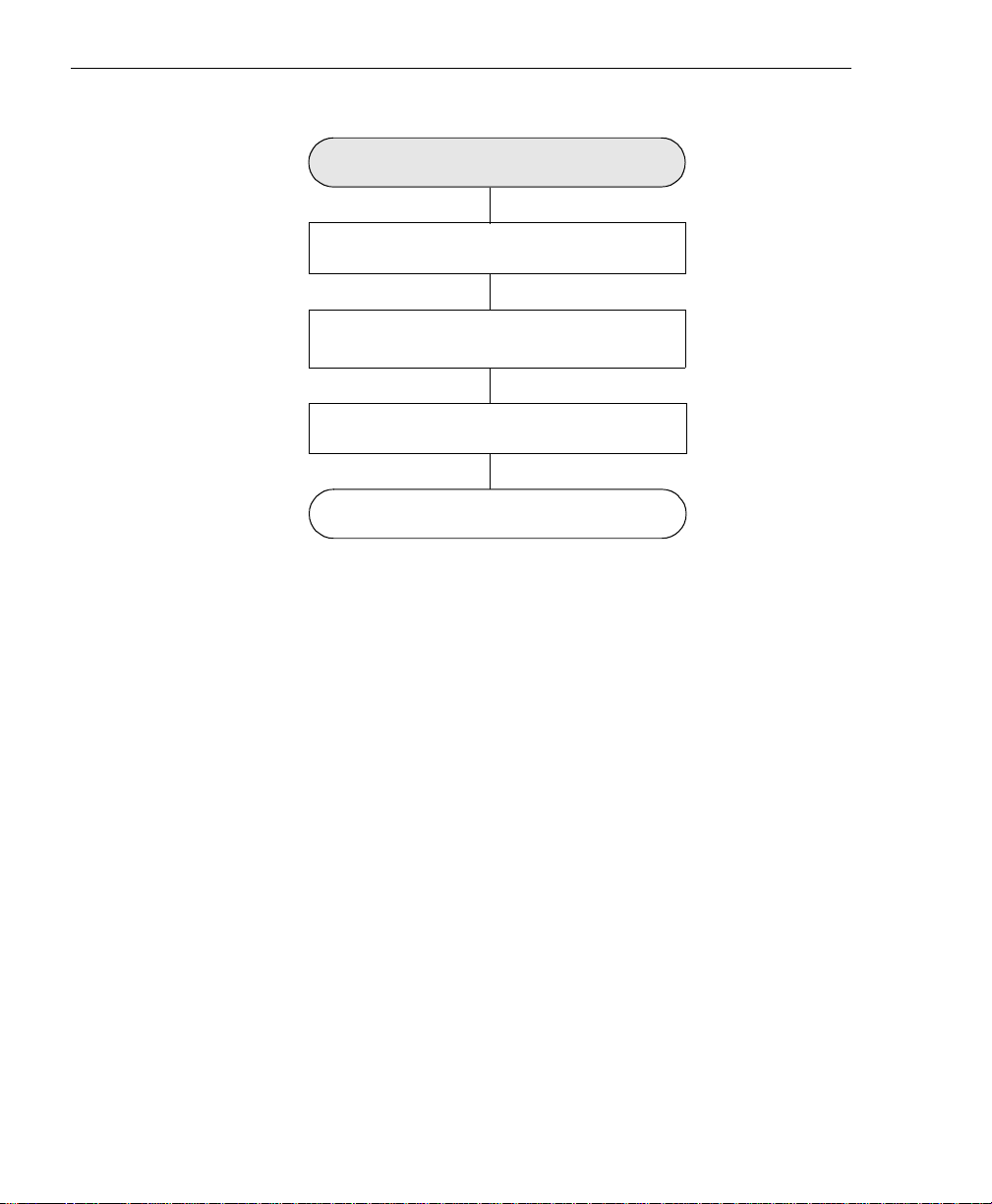
The flow diagram shown in Figure 1 illustrates the steps needed to
get started using the DT3162 board. This diagram is repeated in each
chapter; the shaded area in the diagram shows you where you are in
the getting started procedure.
Prepare to Use the DT3162 Board
(see Chapter 2 starting on page 7)
Install the Board and Configure the Device
Driver (see Chapter 3 starting on page 15)
Connect Signals to the Board
(see Chapter 4 starting on page 23)
Verify Bo ard Operation
(see Chapter 5 starting on page 37)
Overview
1
1
1
1
1
Troubleshoot Issues
(see Chapter 6 starting on page 43)
Figure 1: Getting Started Flow Diagram
1
1
1
1
5
Page 14

Chapter 1
6
Page 15

2
Preparing to Use the
DT3162
Unpacking . . . . . . . . . . . . . . . . . . . . . . . . . . . . . . . . . . . . . . . . . . . . . . 9
Checking the System Requirements . . . . . . . . . . . . . . . . . . . . . . . 10
Installing the Software. . . . . . . . . . . . . . . . . . . . . . . . . . . . . . . . . . . 11
Viewing the DT3162 Documentation . . . . . . . . . . . . . . . . . . . . . . 13
7
Page 16
Chapter 2
Prepare to Use the DT3162 Board
Install the Board and Configure the Device
Driver (see Chapter 3 starting on page 1 5)
Connect Signals to the B oa rd
(see Chapter 4 starting on page 23)
(see Chapter 5 starting on page 37 )
(see Chapter 6 starting on page 43 )
(this chapter)
Verify Board Operation
Troubleshoot Issues
8
Page 17

Unpacking
Open the shipping box and carefully remove the DT3162 frame
grabber board.
Keep the DT3162 board in its protective antistat ic bag until you are
ready to configure and/or install it.
Verify that the following items are present:
Preparing to Use the DT3162
2
2
CAUTION:
2
• DT3162 frame grabber board, and
• Imaging OMNI CD.
If an item is missing or damaged, call Data Translation's Customer
Service Department at (508) 481-3700 x1394. Customer Service will
guide you through the appropriate steps for replacing missing or
damaged items. If you are located outside the USA, call your local
distributor, listed in your Data Translation Product Handbook.
Note: We suggest that you save the original packing material in the
unlikely event that your board requires servicing in the future.
2
2
2
2
2
2
9
Page 18

Chapter 2
Checking the System Requirements
For reliable operation, your DT3162 board requires the following
minimum system requirements:
• Pentium III processor
• At least one available PCI 32-bit, 33 MHz bus master expansion
slot.
• At least 128 MB of RAM.
• A DirectX-compatible graphics adapter set to 24-bit or 32-bit
color.
• At least one CD-ROM drive.
• Window 98, Windows Me, Windows 2000, or Windows XP.
• If you are using the DT-Active Monochrome Frame Grabber
Control, Microsoft Visual Basic 6.0 or higher or Microsoft Visual
C++ 6.0 or higher.
10
Page 19

Installing the Software
To operate properly, the DT3162 board requires the following
software components:
• Microsoft DirectX, version 7.0 or greater,
• DT3162 Device Driver, version 1.0 or greater.
You can install these software components from the Imaging OMNI
CD. To install the DT3162-related software from the Imaging OMNI
CD, perform the following procedure:
Preparing to Use the DT3162
2
2
2
Note: Note that if the DirectX software on your computer is less
than version 7.0, you are prompted to install the updated DirectX
software, which is provided on the Imaging OMNI CD.
1. Insert the Imaging OMNI CD into your CD-ROM drive.
Note that in most systems, the CD will launch automatically. If
your system does not launch the OMNI CD automatically,
perform the following steps:
a. Click Start from the Task Bar, then click Run.
The Run dialog box appears.
b. Either enter x:\LAUNCH.EXE (where x is the letter of your
CD-ROM drive) or use the Browse button to locate
LAUNCH.EXE.
c. Click OK.
The Imaging OMNI CD splash screen appears.
2. Click Install Products.
3. Click MACH II SERIES.
4. Click Install Devices.
2
2
2
2
2
2
11
Page 20

Chapter 2
5. Click DT3162.
If you do not have the proper version of DirectX installed on your
system, you are prompted to install updated DirectX software, which is
provided on the Imaging OMNI CD; afterwards, you must repeat steps
1 to 5. Otherwise, the InstallShield Wizard appears.
6. Click Next.
The license agreement is displayed.
7. Click Ye s to accept the license agreement, then click Finish.
You are prompted to choose your destination location.
8. Click Next.
9. Click Ty pi ca l (which installs the driver, ActiveX control,
examples, and manuals), Compact (which installs only the driver
and ActiveX control), or Custom (which allows you to select the
components to install).
10. Click Next.
11. If you selected Custom, specify the components that you want to
install, then click Next. Otherwise, continue with the next step.
12
12. If you are using Windows 98 or Windows Me, select the Restart
Later option, then click Finish. If you are using Windows 2000 or
Windows XP, click Finish.
13. Click Main Menu, then click Exit.
Page 21

Preparing to Use the DT3162
Viewing the DT3162 Documentation
The DT3162 documentation is installed if you select Typical in the
installation procedure, described in the previous section.
2
You can access these documents through the Data Translation,
Inc\DT3162 program folder, or you can view the DT3162
documentation from the Imaging OMNI CD by performing the
following steps:
Note: This procedure assumes that Adobe Acrobat 4.0 or greater is
installed on your system. Acrobat Reader 5.0 is provided on the
Imaging OMNI CD. If you install Acrobat Reader 5.0 from this CD,
ensure that you open Acrobat Reader and accept the license
agreement before performing the following procedure.
1. Insert the Imaging OMNI CD into your CD-ROM drive.
Note that in most systems, the CD will launch automatically. If
your system does not launch the OMNI CD automatically,
perform the following steps:
a. Click Start from the Task Bar, then click Run.
The Run dialog box appears.
b. Either enter x:\LAUNCH.EXE (where x is the letter of your
CD-ROM drive) or use the Browse button to locate
LAUNCH.EXE.
2
2
2
2
2
2
c. Click OK.
The Imaging OMNI CD splash screen appears.
2. Click Install Products.
3. Click MACH II SERIES.
4. Click Documentation.
5. Click Getting Started Manuals.
2
2
13
Page 22

Chapter 2
6. Click DT3162.
7. View and/or print the PDF manual, then close Adobe Acrobat.
8. Click Main Menu.
9. Click View Documentation.
10. Click User’s Manuals.
11. Click DT3162.
12. View and/or print the PDF manual, then close Adobe Acrobat.
13. Click Main Menu.
14. Click View Documentation.
15. Click DT-Active Frame Grabber Controls (Mach II).
16. View and/or print the PDF manual, then close Adobe Acrobat.
17. Click Main Menu, then click Exit.
14
Page 23

3
Installing the Board and
Configuring the Device Driver
Installing the Board . . . . . . . . . . . . . . . . . . . . . . . . . . . . . . . . . . . . . 17
Loading and Configuring the Device Driver . . . . . . . . . . . . . . . . 21
15
Page 24

Chapter 3
Prepare to Use the DT3162 Board
(see Chapter 2 starting on page 7)
Install the Board and Configure the Device
Driver (this chapter)
Connect Signals to the B oa rd
(see Chapter 4 starting on page 23)
Verify Board Operation
(see Chapter 5 starting on page 37)
Troubleshoot Issues
(see Chapt e r 6 sta r ting on page 43 )
16
Page 25

Installing the Board
To install the board, you need to set up the computer, select an
expansion slot, then insert the board into the computer, as described
in the following sections.
Settin g up the C om p ut er
Installing the Board and Configuring the Device Driver
3
3
CAUTION:
To preven t electr ostatic damage that can occ ur when handling
elec tronic equip m e nt, us e a ground strap or simila r devic e when
performing this installation procedure.
Perform the following procedure to set up the computer:
1. Turn off the computer.
2. Turn off all peripherals (printer, modem, monitor, and so on)
connected to the computer.
3. Remove the cover from your computer. Refer to your computer’s
user manual for instructions.
Next, select an expansion slot, as described in the next section.
3
3
3
3
3
3
3
17
Page 26

Chapter 3
Selecting an Expansion Slot
Perform the following procedure to select an expansion slot:
1. Select a 32-bit, 33 MHz PCI master expansion slot. Refer to your
computer system’s user manual to determine which slots are bus
masters.
PCI slots are shorter than ISA or EISA slots and are usually white
or ivory. Commonly, three PCI slots (one of which may be a
shared ISA/PCI slot) are available. If an ISA board exists in the
shared slot, you cannot use the slot for a PCI board; likewise if a
PCI board exists in the shared slot, you cannot use the slot for an
ISA board.
Note: In most PCI systems, any PCI slot can be a bus master.
2. Remove the cover plate from the selected expansion slot. Retain
the screw that held it in place; you will use it later to install the
board.
18
Next, insert the DT3162 board in the expansion slot, as described in
the next section.
Insert i n g the D T 3162 Board in the C o mputer
To insert the DT3162 board in the computer, perform the following
steps:
1. To discharge any static electricity, hold the wrapped board in one
hand while placing your other hand firmly on a metal portion of
the computer chassis.
2. Carefully remove the antistatic packing material from the board.
(We suggest that you save the original packing material in the
unlikely event that your board requires servicing in the future.)
Page 27

Installing the Board and Configuring the Device Driver
3. Hold the board by its edges and do not touch any of the
components on the board.
4. Position the board so that the cable connectors are facing the rear
of the computer, as shown in Figure 2.
3
3
DT3162 Board
PCI Expansion Slot Bus Connector
Figure 2: Inserting the DT3162 Board in the Computer
5. Carefully lower the board into the PCI expansion slot using the
card guide to properly align the board in the slot. When the
bottom of the board contacts the bus connector, gently press
down on the board until it clicks into place.
CAUTION:
Rear of Computer
3
3
3
3
3
Do not force the board into place. Moving the board from s ide to side
during installation may damage the bus connector. If you encounter
resistance when in serting the boar d, rem ov e the boar d and try aga in.
3
3
19
Page 28

Chapter 3
6. Secure the board in place at the rear panel of the system unit
using the screw removed from the slot cover.
7. Replace the cover and turn on the computer.
When you are finished with this procedure, configure the device
driver using the instructions in the next section.
20
Page 29

Installing the Board and Configuring the Device Driver
Loading and Configuring the Device Driver
If you are using Windows XP, once you install the board and turn the
computer on, the New Hardware Found dialog box appears. Perform
the following steps to load the device driver:
1. Select the option to Install the software automatically
(Recommended), then click Next.
3
3
2. Click Finish.
For all other operating systems, the driver is automatically loaded
when you install the DT3162 software from the Imaging OMNI CD.
Once the driver has been loaded, configure the DT3162 Device Driver
through the DT3162 configuration dialog box. To access the DT3162
configuration dialog box, perform the following steps:
1. Open the Control Panel.
2. Double-click the DT Imaging Control icon.
3. Select the DT3162 board to configure.
The DT3162 configuration dialog box is displayed.
4. If you wish, change the alias (or name) of the board.
5. If you want to use the board, ensure that the Disabled box is not
checked.
6. Click Advanced.
7. By default, the installation program automatically points to the
directory in which the configuration and LUT files were installed.
If you want to change this directory, either enter or browse to the
appropriate folder from which to load or save the configuration
and LUT files.
3
3
3
3
3
3
3
21
Page 30

Chapter 3
8. By default, the installation program selects the rs-170.ccf
configuration file, which is the standard video format in the
United States. If this configuration file does not match your video
format, select the default configuration file to use, then click OK.
The default configuration file for Europe is ccir.ccf.
9. When you are finished, click OK.
When you are finished with this procedure, continue by connecting
signals to the board. Refer to Chapter 4 starting on page 23.
22
Page 31

4
Connecting Signals
Connecting Signals to Connector J1. . . . . . . . . . . . . . . . . . . . . . . . 26
Connecting Signals to Connector J2 . . . . . . . . . . . . . . . . . . . . . . . 35
23
Page 32

Chapter 4
Prepare to U se the DT3162 Board
(see Chapter 2 st arting on page 7)
Install the Board and Load the Device Driver
(see Chapter 3 starting on page 15)
Connect Signals to the Board
(this chapter)
Verify Board Operation
(see Chapter 5 starting on page 37)
Troubleshoot Issues
(see Chapter 6 starting on page 43)
24
Page 33

Connecting Signals
The DT3162 board provides two user connectors: J1 and J2.
Connector J1 brings out the video, sync, pixel clock, trigger input,
and expose/reset signals. Connector J2 brings out the strobe output
and digital I/O signals.
This chapter describes how to connect signals to the board using the
J1 and J2 connectors.
CAUTION:
Always turn off the power to both your computer and the input device
before making these connections. Damage can result if connections
are made with the power on.
4
4
4
4
4
4
4
4
4
25
Page 34

Chapter 4
Connecting Signals to Connector J1
To connect signals to the J1 connector, you can use either of the
following solutions:
• EP332 cable − Provides eight BNC connectors for attaching up to
three video inputs, a horizontal and vertical sync input/output,
an external TTL pixel clock input, a trigger input, and an
expose/reset output signal.
• Camera Interface Module (with the EP321) − A DIN-rail
mountable enclosure that provides a Hirose connector for
attaching a video input, a horizontal and vertical sync
input/output, a TTL pixel clock input, and an expose/reset
output signal; two BNC connectors for attaching two additional
video inputs; a screw terminal block for attaching external +12 V
power; and a screw terminal block for attaching an internal
trigger.
Choose the solution that is most convenient for your application. This
section describes how to connect signals to the board using either of
these solutions.
26
Note: If you need to provide a differential pixel clock input, you
need to build your own cable to mate with connector J1 on the
DT3162 board. Refer to Appendix A and B of the DT3162 User’s
Manual for more information.
Page 35

Using the EP332 Cable
Connecting Signals
To connect signals to connector J1 on the DT3162 board using the
optional EP332 cable, perform the following steps:
1. After making sure power to the computer is off, push the
connector end of the EP332 cable into the J1 socket at the rear of
the DT3162 board, as shown in Figure 3, and tighten the screws
on the connector.
HSYNC
TRIGGER
EXP RESET
VIDEO 0
VIDEO 1
VIDEO 2 PIX CLK B (TTL)
Figure 3: Connecting the EP332 Cable Assembly to Connector J1
VSYNC
EP332
J1
DT3162
J2
4
4
4
4
4
4
2. Connect a video source to EP332 connector VIDEO 0, VIDEO 1,
or VIDEO 2.
Note: The EP332 cable terminates in female BNC connectors;
this allows you to easily connect to a standard male BNC to BNC
cable of the desired length or to the EP261 cable).
4
4
4
27
Page 36

Chapter 4
3. If you are using an external sync input or output, attach the
horizontal sync input/output to EP332 connector HSYNC and
the vertical sync input/output to EP332 connector VSYNC.
4. If you are using an external trigger source, attach the output of
the external trigger source to EP332 connector TRIGGER.
5. If you are using an external TTL-level pixel clock, attach the
output of the clock source to EP332 connector PIX CLK B.
6. If you are using an asynchronous reset camera, attach the
expose/reset input of your camera to EP332 connector EXP
RESET.
Once you have connected all the required signals to the DT3162
board, apply power to the computer, then apply power to your video
source.
Using the Camera Interface Module
This section assumes that you have purchased an optional Camera
Interface Module; the EP321 cable is shipped with the Camera
Interface Module.
28
To connect signals to connector J1 on the DT3162 board using the
Camera Interface Module, perform the following steps:
1. After making sure power to the computer is off, push one end of
the EP321 cable into the J1 socket at the rear of the DT3162 board,
push the other end of the EP321 cable into the VCP connector of
the Camera Interface Module, and tighten the screws on both
connectors. Figure 4 illustrates this step.
Page 37

Connecting Signals
CAMERA
+12 V
TRIGGER
Figure 4: Connecting the Camera Interface M od ul e to Connect or J1
2. Connect a video source to either the CAMERA Hirose connector
Camera Interface
Module
VCP
(in software this connector is referred to as VIDEO 0), the
VIDEO 1 BNC connector, or the VIDEO 2 BNC connector on the
Camera Interface Module.
The cable that connects to the CAMERA connector is specific to
the camera used and should be provided by the camera
manufacturer. The CAMERA connector has 12 pins which
correspond to many of the signals brought out from the J1
connector on the DT3162 board. The configuration of the
jumpers, described in step 6, determines which signals are
available to the camera.
VIDEO 1
EP321
J1
DT3162
J2
VIDEO 2
4
4
4
4
4
4
4
The EP261 cable, available from Data Translation, is available for
connecting a composite video signal to a BNC connector on the
Camera Interface Module.
3. If you are using an external trigger source, attach the output of
the external trigger source to the TRIGGER screw terminals on
the Camera Interface Module.
4
4
29
Page 38

Chapter 4
4. If you want to provide +12 V to the video source connected to the
CAMERA connector, attach a +12 VDC power supply to the
+12 V screw terminals on the Camera Interface Module.
5. Using a flat screw driver, lift the round metal cover on the
Camera Interface Module to expose the camera jumpers, as
shown in Figure 5.
Camera Interface
Module
Remove Cover By Lifting it
with a Flat Screw Driver
Camer a J ump er s
30
W1
W2
W3
TP1
W5
W10
TP3
Note: By default, jumpers W1, W3, W4, and W11 are installed.
W4
W6
TP5 TP6
W7
W9
W11
SP1
W8
TP2
TP4
Figure 5: Exposing the Camera Jumpers on the Camera Inter face Module
Page 39

6. Install the camera jumpers according to your camera
configuration. Ta ble 4 lists the pin assignments of the CAMERA
connector on the Camera Interface Module; Ta bl e 5 summarizes
the function of each camera jumper.
WARNING!
Refer to you camera documentation before configuring pins 6
through 11 of the CAMERA connector on the Camera Interface
Module. Misconfiguration of pin 11 may cause damage to the
DT3162, Camera Interface Module, and/ or your camera.
Connecting Signals
4
4
4
Table 4: CAMERA Connector Pin Assignments
Pin Description Pin Description
1 Digital Ground 2 +12 V
3 Video 0 Return 4 Video 0
5 Digital Ground 6 HSync or Expose/ Reset
7 VSync or Expose/Reset
9 HSync, Pixel Clo ck, or
Expose/Reset
11 Pixel Clock,
Expose/Reset, or +12 V
a. This is the input from the 12 VDC terminal block.
b. To access the HSync signal on pin 6, install jumper W3 (by default, this jumper is
installed); or to access the Expose/Reset signal on pin 6, install jumper W2.
c. To access the VSync signal on pin 7, install jumper W11 (by default, this jumper is
installed); or to access the Expose/Reset signal on pin 7, install jumper W10.
d. To access the HSync signal on pin 9, install jumper W5; to access the Pixel Clock signal
on pin 9, install jumper W6; or to access the Expose/Reset signal on pin 9, install jumper
W4 (by default, this jumper is installed).
e. To access the Digital Ground signal on pin 10, install jumper W1 (by default, this jumper
is installed). If jumper W1 is not installed, this pin is not connected to any signal.
d
c
8 Digital Ground
10 Digital Ground or Not
12 Digital Ground
a,f
a
Connected
e
4
4
b
4
4
4
4
31
Page 40

Chapter 4
f. To access the Pixel Clock signal on pin 11, install jumper W9; to access the Expose/Reset
signal on pin 11, install jumper W7; or to access the+12 V signal on pin 11, install jumper
W8 and place a short across Solder Pad 1 (SP1).
Table 5: Camera Interface Module Jumpers
Jumpers
a
Pin Affected Signal Description
W1 10 If this jumper is installed (the default
configuration), the Digital Ground signal is
accessible on pin 10 of the CAMERA
connector. If this jumper is not installed, pin 10
has no signal connected to it.
W2 6 If this jumper is installed, the Expose/Reset
signal is accessible on pin 6 of the CAMERA
connector.
W3 6 If this jumper is installed (the default
configuration), the HSync signal is accessible
on pin 6 of the CAMERA connector.
W4 9 If this jumper is installed (the default
configuration), the Expose/Reset signal is
accessible on pin 9 of the CAMERA connector.
W5 9 If this jumper is installed, the HSync signal is
accessible on pin 9 of the CAMERA connector.
W6 9 If this jumper is installed, the Pixel Clock signal
is accessible on pin 9 of the CAMERA
connector.
b
W7
11 If this jumper is installed, the Expose/Reset
signal is accessible on pin 11 of the CAMERA
connector.
32
W8 and
Solder Pad 1
11 If this jumper is installed, the +12 V signal is
b,c
accessible on pin 11 of the CAMERA
connector.
Page 41

Table 5: Camera Interface Module Jumpers (cont.)
Connecting Signals
Jumpers
b
W9
W10 7 If this jumper is installed, the Expose/Reset
W11 7 If this jumper is installed, the VSync signal is
a. If a specified jumper is installed, the corresponding signal is available to the camera on the
pin specified. If a specified jumper is not installed, the corresponding signal is not available
to the camera on the pin specified. Only one jumper corresponding to a pin can be installed
at a time.
b. Misconfiguration of this jumper can cause damage to the DT3162, Camera Interface Module,
or your camera.
c. If your camera requires 12 V on pin 11, you need to install jumper W8 and place a short
across Solder Pad 1 (SP1).
a
7. If you wish, use test points TP1 to TP6 to debug your camera set
Pin Affected Signal Description
11 If this jumper is installed, the Pixel Clock signal
is accessible on pin 11 of the CAMERA
connector.
signal is accessible on pin 7 of the CAMERA
connector.
accessible on pin 7 of the CAMERA connector.
By default, this jumper is installed.
up. Tab l e 6 describes the function of test points TP1 to TP6.
4
4
4
4
4
4
Table 6: Test Point Descriptions
Tes t Poin ts Description Test Points Description
TP1 Digital Ground TP4 Vertical Sync
TP2 Pixel Clock 1
TP3 Horizontal Sync TP6 Trigger
a. Pixel Clock 1 is a TTL-level signal from the camera that is converted to an LVDS
differential signal (PIX CLK1+ and PIX CLK1-) for the DT3162 board.
a
TP5 Expose/Reset
4
4
4
33
Page 42

Chapter 4
8. Once you have connected all the required signals to the DT3162
board, apply power to the computer, then apply power to your
video source.
Note: When +12 V power is applied to the Camera Interface
Module, the LED next to the +12 V connector lights.
When the Camera Interface Module detects the rising edge of an
expose/reset pulse that is output from the DT3162 board, the LED
next to the TRIGGER connector lights momentarily.
34
Page 43

Connecting Signals to Connector J2
This section assumes that you have purchased an optional STP15
screw terminal panel; the EP337 cable is shipped with the STP15.
Connecting Signals
4
To connect signals to connector J2 on the DT3162 board, perform the
following steps:
1. Make sure power to the computer is off.
2. Push one end of the EP337 cable into the J2 socket at the rear of
the DT3162 board, then push the other end of the EP337 cable
into the STP15 screw terminal panel. Figure 6 illustrates this step.
J1
EP337
STP15
Figure 6: Conn e c ting t h e STP15 to the DT3162 Board
J2
DT3162
4
4
4
4
4
4
3. Connect digital input, digital output, and/or strobe output
signals to the screw terminals of the STP15. Figure 7 shows the
layout of the STP15 and the signal descriptions for each screw
terminal.
4
4
35
Page 44

Chapter 4
J1, 15-Pin Connector
TB1
IN0
IN1
DGND
IN2
IN3
DGND
STROBE
DGND
DGND
DGND
OUT3
OUT2
DGND
OUT1
OUT0
TB2
+5 V
Figure 7: Layout of the STP15 Screw Terminal Panel
Notes: In Figure 7, IN refers to digital input signals, OUT refers to
digital output signals, STROBE refers to strobe output signal, DGND
refers to digital ground signals, and +5 V refers to a +5 V (100 mA)
output signal from the DT3162 board.
36
The dark filled circles in Figure 7 represent holes that you can use to
mount the STP15 on a DIN rail. To mount the STP15 on a DIN rail,
you need two DIN rail mount adapters (Phoenix Contact part
number 1201578 or Data Translation part number 18083), and four
thread form screws (Bossard part number BN2724M3x8 or Data
Translation part number 18193).
Page 45

5
Verifying Board Operation
Overview . . . . . . . . . . . . . . . . . . . . . . . . . . . . . . . . . . . . . . . . . . . . . . 39
Using DT-Acquire2. . . . . . . . . . . . . . . . . . . . . . . . . . . . . . . . . . . . . . 40
37
Page 46

Chapter 5
Prepare to U se the DT3162 Board
(see Chapter 2 st arting on page 7)
Install the Board and Load the Device Driver
(see Chapter 3 starting on page 15)
Connect Signals to the Board
(see Chapter 4 starting on page 23)
Verify Bo ard Operation
(this chapter)
Troubleshoot Issues
(see Chapter 6 starting on page 43)
38
Page 47

Overview
The DT-Acquire2 example program provides a quick way to verify
that your board is properly installed, that the camera or cameras are
properly connected, and that you can acquire images.
Verifying Board Operation
5
DT-Acquire2 allows you to
• Acquire either a single image or continuous images,
• Open a previously saved BMP image,
• Save an acquired image in BMP format,
• Load a configuration file,
• Save a configuration file, and
• Perform a digital I/O operation.
DT-Acquire2 is automatically installed when you install the DT3162
software providing that you select either the Typical installation
option or the Custom installation option with Example Applications
checked (see page 11 for more information).
5
5
5
5
5
5
5
5
39
Page 48

Chapter 5
Using DT-Acquire2
To start DT-Acquire2, click the DT-Acquire2 icon in the Data
Translation, Inc\DT3162\ program group. The main menu is
displayed.
Note: For specific information about the components of
DT-Acquire2, click Help from the DT-Acquire2 main menu, then
click DT-Acquire2 Help Topics.
To use DT-Acquire2, perform the following steps:
1. Connect a video input signal to video source 0, 1, or 2; connect
control signals and strobe, expose/reset, and digital I/O signals,
as needed. Refer to Chapter 4 starting on page 23 for more
information.
2. From the DT-Acquire2 main menu, click File, then Select Device.
40
3. Select the alias that you gave to the DT3162 board when you
configured the device driver, then click OK.
4. Click Setup, then click Ti meout, and enter a value to indicate
when the acquisition should timeout if a valid video signal is not
present.
5. To use an existing configuration, click File, click Load/Save
Configuration File, highlight the file to use, click Load, then go
to step 12. Otherwise, continue with step 6.
6. Click Setup, then click Configure.
7. Use the Input tab to configure the sync input signals, input video
source, trigger, and pixel clock source, then click OK.
Page 49

Verifying Board Operation
8. Use the Output tab to configure the sync output (if used) or to set
up the strobe and expose output pulses, if desired. Note that if
you enable either strobe or expose, the pulses are output when
you start the acquisition. When you are finished with this tab,
click OK.
5
9. Use the Capture tab to configure the video signal, region of
interest, and the brightness and contrast settings. You can see the
effect of these changes by selecting either Start Continuous
Acquire or Single Frame Acquire. To stop a continuous acquire
operation, select Stop Continuous Acquire. When you are
finished with this tab, click OK.
10. Use the LUT tab to select the look-up table to use, then click OK.
By default, LUT 0 uses the identity pattern; LUT 1 uses the
inverse pattern.
The display window shows the results of applying the values in the LUT
to the incoming video.
11. To save this configuration, click File from the DT-Acquire2 main
menu, click Load/Save Configuration File, click Save, enter the
name of the configuration file, the name of the creator of the file
(optional), and a short description of the file (optional), then click
OK.
12. From the DT-Acquire2 main menu, click Run, then click either
Start Continuous Acquire or Single Frame Acquire.
Images are acquired and displayed on the screen.
13. To save an image if desired, click File from the DT-Acquire2 main
menu, then click Save Image File.
5
5
5
5
5
5
14. To perform a digital I/O operation, click Setup, then click Digital
I/O
To read the digital input line, click Read. To perform a digital
.
output operation, set the digital output values appropriately; the
selected values are written immediately to the digital output
lines. Click OK when you are finished with this menu option.
15. When you are finished with this program, click File from the
DT-Acquire2 main menu, then click Close Device and close the
application.
5
5
41
Page 50

Chapter 5
42
Page 51

6
Troubleshooting
General Checklist . . . . . . . . . . . . . . . . . . . . . . . . . . . . . . . . . . . . . . . 45
Service and Support . . . . . . . . . . . . . . . . . . . . . . . . . . . . . . . . . . . . . 50
If Your Board Needs Factory Service. . . . . . . . . . . . . . . . . . . . . . . 54
43
Page 52

Chapter 6
Prepare to U se the DT3162 Board
(see Chapter 2 st arting on page 7)
Install the Board and Load the Device Driver
(see Chapter 3 starting on page 15)
Connect Signals to the B oa rd
(see Chapter 4 starting on page 23)
Verify Bo ard Operation
(see Chapter 5 starting on page 37)
Troubleshoot Issues
(this chapter)
44
Page 53

General Checklist
Should you experience problems using the DT3162 board, follow
these steps:
1. Read all the documentation provided for your product. Make
sure that you have added any “Read This First” information to
your manual and that you have used this information.
2. Check the Imaging OMNI CD for any README files and ensure
that you have used the latest installation and configuration
information available.
3. Check that your system meets the requirements stated on page
10.
4. Check that you have installed the software properly using
instructions starting on page 11.
5. Check that you have installed your hardware properly using the
instructions starting on page 17.
6. Check that you have configured the device driver properly using
the instructions on page 21.
Troubleshooting
6
6
6
6
6
7. Search the DT Knowledgebase in the Support section of the Data
Translation web site (at www.datatranslation.com) for an answer
to your problem.
If you still experience problems, try using the information in Ta b le 7
to isolate and solve the problem. If you cannot identify the problem,
refer to page 50.
6
6
6
6
45
Page 54

Chapter 6
Table 7: Troubleshooting Problems
Symptom Possible Cause Possible Solution
Board does not
respond.
The board is
incorrectly aligned in
a PCI expansion slot.
The interrupt level is
unacceptable.
Check that the slot in which your DT3162
board is located is a PCI slot and that the
board is correctl y seated in the slot; see
the instructions starti ng on page 17
An interrupt conflict exists in your system.
The most comm on interrupt conflict
occurs with a PCI device and a device that
is plugged i nto the ISA bus. To resolv e this
problem, change the interrupt setting
(usually by chang ing a jumper) on the ISA
device.
An interrupt conflict can also occur if a PCI
device was not designed to share
interrupts. To resolve this pr oblem, select
a diff erent interrupt for each PCI slot in the
PCI BIOS. To do this, enter the system
BIOS program; this is usually done by
pressing t he DEL k ey when rebooting your
system. Once in the system BIOS, enter
the PCI/PnP BIOS setup, and select a
unique interrupt f or each PCI slot. The PCI
BIOS assigns the interrupt; the device on
the PCI bus does not have control over the
interrupt a ssignment.
.
46
The board is
damaged.
The recalibrate
operation failed.
Some network devices do not share
interrup t s. I f yo u stil l have an interrupt
conflict, try removi ng the network device,
installing t he DT3162 boa rd an d reboot ing
the system, then reinse rting the network
device.
Contact Data Translation for technical
support; refer to page 50.
Contact Data Translation for technical
support; refer to page 50.
Page 55

Table 7: Troubleshooting P roblems (cont.)
Troubleshooting
Symptom Possible Cause Possible Solution
Intermittent
operation.
Data appears to
be invalid.
Computer does
not boot.
Loose connections or
vibrations exist.
Electrical noise exists. Check your connections; see the
The board is
overheating.
Wiring is not
connected properly.
Board is not seated
properly.
Check your wiring and tighten any loose
connections or cushion vibration sources;
see the instructions in Chapter 4 starting
on page 23.
instructions in Chapter 4 starting on page
23.
Check environmental and ambient
temperature; consult the board’s
specifications i n Appendix A of the
DT3162 User’s Manual
documentation p ro vided b y yo ur computer
manufacturer for more information.
Check your wiring and fix any open
connections; see the instructions in
Chapter 4 starting on page 23.
Check that the slot in which your DT3162
board is located is a PCI slot, that the
board is correctl y seated in the slot, and
that the board is secured in the slot with a
screw; see the instructions in the
Getting Started Manual.
and the
DT3162
6
6
6
6
6
6
The power supply of
the computer is too
small to handle a ll th e
system resources.
Check the power requirements of your
system resources and, if needed, get a
larger power supply; consult the board’s
specifications i n Appendix A of the
DT3162 User’s Manual
.
6
6
6
47
Page 56

Chapter 6
Table 7: Troubleshooting P roblems (cont.)
Symptom Possible Cause Possible Solution
System locked
up.
Board is not seated
properly.
Interrupt level is
unacceptable.
Check that the slot in which your DT3162
board is located is a PCI slot, that the
board is correctl y seated in the slot, and
that the board is secured in the slot with a
screw; see the instructions starting on
page 17
An interrupt conflict exists in your system.
The most comm on interrupt conflict
occurs with a PCI device and a device that
is plugged i nto the ISA bus. To resolv e this
problem, change the interrupt setting
(usually by chang ing a jumper) on the ISA
device.
An interrupt conflict can also occur if a PCI
device was not designed to share
interrupts. To resolve this pr oblem, select
a diff erent interrupt for each PCI slot in the
PCI BIOS. To do this, enter the system
BIOS program; this is usually done by
pressing t he DEL k ey when rebooting your
system. Once in the system BIOS, enter
the PCI/PnP BIOS setup, and select a
unique interrupt f or each PCI slot. The PCI
BIOS assigns the interrupt; the device on
the PCI bus does not have control over the
interrupt a ssignment.
.
48
Some network devices do not share
interrup t s. I f yo u stil l have an interrupt
conflict, try removi ng the network device,
installing t he DT3162 boa rd an d reboot ing
the system, then reinse rting the network
device.
Page 57

Table 7: Troubleshooting P roblems (cont.)
Troubleshooting
Symptom Possible Cause Possible Solution
Images are
scrambled.
Acquisition
operation timed
out.
The capture
properties are not set
appropriately.
The capture
properties are not set
appropriately.
Wiring is not
connected properly.
Refer to the d ocumentation for your
camera or i mage device a nd set t he
capture properties to match the
requirements of your device. Refer to the
DT3162 User’s Manual
and to the FGXMONO.HLP file on the
Imaging OMNI CD for more information.
Refer to the d ocumentation for your
camera or i mage device a nd set t he
capture properties to match the
requirements of your device. Refer to the
DT3162 User’s Manual
and to the FGXMONO.HLP file on the
Imaging OMNI CD for more information.
Check your wiring and fix any open
connections; see the instructions in
Chapter 4 starting on page 23.
(UM3162.PDF)
(UM3162.PDF)
6
6
6
6
6
6
6
6
6
49
Page 58

Chapter 6
Service and Suppo rt
If you have difficulty using the DT3162 board, Data Translation’s
Technical Support Department is available to provide prompt
technical assistance. Support upgrades, technical information, and
software are also available.
All customers can always obtain the support needed. The first 90
days are complimentary, as part of the product’s original warranty, to
help you get your system running. Customers who call outside of this
time frame can either purchase a support contract or pay a nominal
fee (charged on a per-incident basis).
For “priority support,” purchase a support contract. Support
contracts guarantee prompt response and are very affordable; contact
your local sales office for details.
Refer to the Data Translation Support Policy located at the end of this
manual for a list of services included and excluded in our standard
support offering.
50
Telephone Technical Support
Telephone support is normally reserved for original warranty and
support-contract customers. Support requests from non-contract or
out-of-warranty customers are processed after requests from original
warranty and support-contract customers.
For the most efficient service, complete the form on page 52 and be at
your computer when you call for technical support. This information
helps to identify specific system and configuration-related problems
and to replicate the problem in house, if necessary.
You can reach the Technical Support Department by calling
(508) 481-3700 x1401.
Page 59

Troubleshooting
If you are located outside the USA, call your local distributor. The
name and telephone number of you nearest distributor are provided
in your Data Translation catalog.
If you are leaving a message to request a support call, include the
following information:
• Your name (include proper spelling),
• Your company or organization (include proper spelling),
6
6
• A phone number,
• An e-mail address where you can be reached,
• The hardware/software product you need help on,
• A summary of the issue or question you have,
• Your contract number, if applicable, and
• Your product serial number or purchase date.
Omitting any of the above information may delay our ability to
resolve your issue.
6
6
6
6
6
6
6
51
Page 60

Chapter 6
Information Required for Technical Support
Name:___________________________________________Phone__________________________
Contr act Number: ______________________________________________ ____________________
Address: _________________________________________________________________________
________________________________________________________________________________
Data Translation hardware product(s): __________________________________________________
serial number:_________________________________________________________________
configuration: _________________________________________________________________
Data Translation device driver - SPO number:___________ ________________________________
_______________________________________________ version: _________________________
Data Translation software - SPO number:_______________ ________________________________
serial number:________________________________ version:__________________________
PC make/model: ___________________________________________________________________
operating system: _____________________________ version:__________________________
Windows version: ______________________________________________________________
processor: ___________________________________ speed:___________________________
RAM: _______________________________________ hard disk space:____________________
network/number of users: _______________________ disk cache:________________________
graphics adapter: _____________________________ data bus:_________________________
I have the following boards and applications installed in my system:____________________________
________________________________________________________________________________
________________________________________________________________________________
I am enc ountering the following problem(s): ______________________________________________
________________________________________________________________________________
________________________________________________________________________________
________________________________________________________________________________
and have received the following error messages/codes: ____________________________________
________________________________________________________________________________
________________________________________________________________________________
I have run th e board di agno st ic s w ith the following results: ___________________________ _______
________________________________________________________________________________
You can reproduce the problem by perfor ming these steps:
1._______________________________________________________________________________
________________________________________________________________________________
2._______________________________________________________________________________
________________________________________________________________________________
3._______________________________________________________________________________
________________________________________________________________________________
52
Page 61

E-Mail and Fax Support
Troubleshooting
You can also get technical support by e-mailing or faxing the
Technical Support Department:
• E-mail: You can reach Technical Support at the following address:
tsupport@datx.com
Ensure that you provide the following minimum information:
− Yo u r n a m e ,
− Your company or organization,
− A phone number,
− An e-mail address where you can be reached,
− The hardware/software product you need help on,
− A summary of the issue you are experiencing,
− Your contract number, if applicable, and
− Your product serial number or purchase date.
Omitting any of the above information may delay our ability to
resolve your issue.
• Fax: Photocopy and complete the form on page 52, then fax
Technical Support at the following number: (508) 481-8620.
6
6
6
6
6
6
Support requests from non-contract and out-of-warranty customers
are processed with the same priority as telephone support requests.
World-Wide Web
For the latest tips, software fixes, and other product information, you
can always access our World-Wide Web site free of charge at the
following address: http://www.datatranslation.com
6
6
6
53
Page 62

Chapter 6
If Your Board Needs F a ctory Service
If your board must be returned to Data Translation, perform the
following steps:
1. Record the board’s serial number, then contact the Customer
Service Department at (508) 481-3700 (if you are in the USA) and
obtain a Return Material Authorization (RMA).
If you are located outside the USA, call your local distributor for
authorization and shipping instructions. The name and
telephone number of your nearest distributor are listed in your
Data Translation catalog.
All return shipments to Data Translation must be marked with
the correct RMA number to ensure proper processing.
2. Using the original packing materials, if available, package the
board as follows:
− Wrap the board in an electrically conductive plastic material.
Handle with ground protection. A static discharge can destroy
components on the board.
54
− Place in a secure shipping container.
3. Return the board to the following address, making sure the RMA
number is visible on the outside of the box.
Customer Service Dept.
Data Translation, Inc.
100 Locke Drive
Marlboro, MA 01752-1192
Page 63

Index
A
accessories
Camera Interface Module
EP261 cable
EP321 cable
EP332 cable
EP337 cable
STP15 screw terminal panel
ActiveX control
Adobe Acrobat Reader, using
4
4
4,
4,
27
35
3
4
4
13
C
cables
EP261
EP321
EP332
EP337
CAMERA connector
Camera Interface Module
checking system requirements
CIM
connecting signals
to connector J1
using the Camera Interface Module
using the EP332 cable
using the EP337 cable
using the STP15
conventions used
customer service
28
4
28
4,
27
4,
35
4,
31
28
4,
10
4
26
27
35
35
vi
54
D
DT Vision Foundry 3
DT3162 Device Driver
DT3162 documentation, installing
DT-Acquire2
DT-Active Monochrome Frame
Grabber Control
3,
40
3
E
e-mail support 53
EP261 cable
EP321 cable
EP332 cable
EP337 cable
expansion slot
selection
4
28
4,
27
4,
35
4,
10
18
F
factory service 54
fax support
G
GLOBAL LAB Image/2 3
53
H
help 45
3
13
55
Page 64

Index
I
inserting the board in the computer 18
installing the DT3162 documentation
13
installing the software
11
J
J1 connector 26
J2 connector
jumpers
35
32
P
pin assignments, CAMERA connector
31
R
related documents vi
requirements
returning boards to the factory
RMA
54
10
54
Worl d Wide Web
system requirements
T
technical support 50
e-mail
fax
telephone
World-Wide Web
telephone support
troubleshooting
procedure
service and support procedure
troubleshooting table
53
53
50
45
U
unpacking the board 9
V
verifying board operation 39
53
10
53
50
50
46
56
S
screw terminal panel layout 36
selecting an expansion slot
service and support procedure
setting up the computer
slot selection
software supported
STP15 screw terminal panel
support
e-mail
fax
53
telephone
53
18
3
50
18
17
4,
35
W
World-Wide Web 53
50
 Loading...