

TRACKER 300 SERIES PROCESS CONTROLLER INSTALLATION GUIDE 30-5012 ISSUE D
1. Introduction
The Tracker 300 provides solutions for the following applications:
• Data acquisition.
• Signal conditioning.
• Condition monitoring.
• Alarm trip.
•PID control.
2. Safety and EMC Information
Safety EN61010-1:2001
Susceptibility EN61326:1998
Emissions EN61326:1998
CE certified 2004
Warnin g: This instrument is marked with the international hazard
symbol. It is important to read this Installation Guide
before installing or commissioning the instrument as it
contains important information relating to safety and
Electromagnetic Compatibility EMC.
Warnin g: This instrument must be fitted within an enclosure that
provides adequate protection against electric shocks.
Warnin g: The mains terminals must use ferrules.
The unit is double insulated.
Note: Ensure that the power to the instrument is switched off before
carrying out any installation or maintenance work.
3. Installation
To install the instrument, you will need to carry out the following steps:
Make connections to the instrument as shown in Section 4 Connections.
1. Attach the instrument on a DIN rail.
To do this, latch the DIN rail recess on
the back of the instrument on the DIN
rail top runner.
2. Insert a screwdriver into the aperture
on the spring-loaded securing clip
located on the back of the instrument.
3. Lever the screwdriver upward to slide
the clip away from the instrument
(take care not to exert too much
pressure on the instrument casing).
Ensure the recess is located around
both the top and bottom DIN rail
runners then release the clip to
securely lock the instrument on the
DIN rail.
Note: •Avoid installing the instrument close to strong magnetic fields,
e.g. switch gear, contactors or motor starters.
•It is recommended that all connections to the terminals are
made using ferrules to provide greater reliability and to prevent
short circuits between adjacent terminals.
•Do not place signal and power supply wiring in the same loom.
•Use screened cables or wires for all signal/sensor leads with
the screen earthed at one end only.
•The DIN rail should be earthed to ensure the best performance
of the instrument.
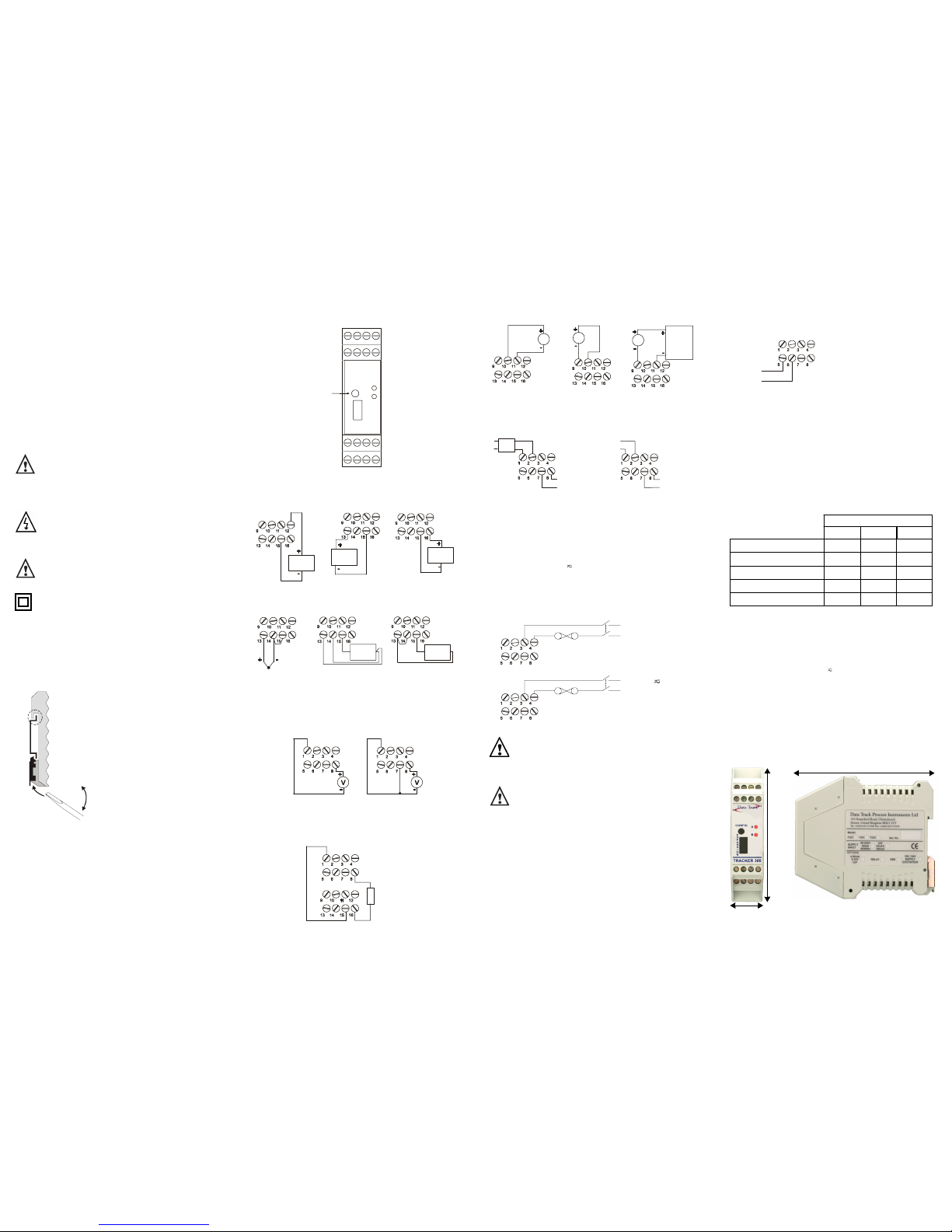
4. Connections
The diagram below shows the terminal connection arrangement.
Analogue Input Connections
10V Voltage Input 100mV Input 20mA Input
Thermocouple RTD (3-wire) RTD (2-wire)
TPSU Connections (Transducer Power Supply) T321
& T332 only
24V DC 10V DC
Two Wire Transmitter Connections (T321 & T332 only)
(24V, 4–20mA input)
Analogue Output Connections (optional)
Voltage Out Current Out (source) Current Out (sink)
T331 Logic Outputs
Relay/SSR Connections (T331) Relay Connections (T331)
5. Powering the Instrument
The AC mains supply version operates with voltages in the range 90230V
≈ @ 50/60Hz. The low voltage version operates from an AC/DC
supply in the range 10-32V .
The diagram shows how the instrument should be connected to the
appropriate supply. Isolation should be provided by a double pole switch
and a 630mA or 1A time-delay fuse as appropriate (see diagram below).
The isolation switch must be readily accessible.
Warni ng: This instrument is designed for installation in an enclosure
that provides adequate protection against electric shocks.
Access to power terminals should be restricted to authorised,
skilled personnel only. Application of supply voltages higher
than those for which the instrument is intended may
compromise safety and cause permanent damage.
Warni ng: Ensure the power supply is connected to the terminals
marked 3 & 4 as shown in the diagram above.
6. Indicators
There are two LEDs located on the front panel of the instrument, identified
as A and B as shown in the terminal connection arrangement diagram.
LED A – can represent four different functions:
1. When lit, it confirms that the instrument is receiving mains power.
2. When flashing fast (approx. 4Hz), it indicates that there is a
system error.
3. When flashing slowly (approximately 1 second per cycle), it
indicates that there is a process error, e.g. sensor break.
4. When flickering, it indicates that the serial communication
interface is transmitting.
LED B – functions are user programmable
7. Serial Communications
The instrument can be configured using either of its serial interfaces:
1. Connection to the RS485 interface is as shown below.
2. Connection to the front panel configuration socket is via a special
cable. The main RS485 interface is disconnected when the
configuration socket is in use.
There are no internal links or potentiometers. There is no reason to open
the instrument.
The Windows compatible software supplied provides access to all
configuration parameters and allows all setup files to be named and stored
for future use. Full context-sensitive help and an online User Guide are
available at all times when using the configuration software. The RS485
interface can also be used to access real time values, i.e. measurements,
values, alarm setpoints.
8. Specification
*Requires an analogue output or Tracker 340 module for PID control.
†
Optionally 2× relay (replaces SSR drive).
Power Requirements
AC mains supply 90-230V≈ 50mA 50/60Hz
Low Voltage
10-32V 300mA
Operating Conditions
Ambient temperature Storage -10°C to 70°C.
Operating 0°C to 60°C.
Humidity 10% to 95% RH non-condensing.
Physical/Mechanical
T330 module Weight 167g (max) packed weight 223g.
Dimensions
1
2
3
A
B
CONFIGURATION
LEAD SOCKET
1234
57
68
9101112
13 1514 16
Volt age
Source
mV
Source
mA
Source
RTD
RTD
+
-
Transmitter
C - Common A two relay version of the T331 is
available where the second relay
replaces the SSR drive.
NO - Normally Open
V
A
External
Supply
A
NO
C
RELAY2
NO
C
RELAY1
NO
C
RELAY1
SSR
+
-
L(+)
Neutral
N(-)
Live (~)
90-230V
50/60Hz
≈
(630mA)
(+)
_
(-)
+
10-32V
AC/DC
(1A)
A
B
MODEL NU MBER
Tracker 321 Tracker 331 Tracker 332
Universal Input + RS485 Interface
✔✔✔
Sensor Excitation (10/24V DC)
✔✔
Analogue Output (Option)
✔✔✔
Auto-tune PID C ontrol
✔✔*
1 x Relay + 1 x SSR Outputs
✔
†
112.6mm
22.5mm
99.0mm
Note: Depth is 114.5mm when mounted
on DIN rail TS35/TS35D
TRACKER 300 SERIES PROCESS CONTROLLER INSTALLATION GUIDE 30-5012 ISSUE D
Voltage & Current Inputs
Ranges ±100mV, ±10V DC and ±20mA DC.
Input Impedance (Ohms) >500MΩ, >1MΩ and <5Ω.
Sensor Excitation Supply (Tracker 321 and 332 only)
2-wire loop supply 24V DC nominally @ 35mA max.
Bridge supply 10V DC regulated @ 35mA max.
Isolation functional isolation only.
Thermocouple Measurement
Resistance Thermometers
Configuration 2 or 3 wire.
Communications Interface
Isolation 500V DC/peak AC.
Type RS485 2-wire multidrop.
Protocols MODBUS RTU & ASCII, DTPI (ASCII)
Analogue Output
Isolation 500V DC/peak AC.
Output Selectable 0 to 10V, 0 to 20mA or 4 to 20mA.
Maximum current output 22mA @ 18V.
Maximum voltage output 11V @ 22mA.
Maximum load (mA output) 900 Ohms.
Logic Outputs (Tracker 331 only)
Relay type 1 x normally open contacts. (Optionally 2.)
Rating 1A @ 230V AC, 1A @ 30V DC.
Relay isolation Isolated from each other and all other inputs
and outputs.
SSR drive output 18V DC 20mA nominal
(see also Tracker 340 Logic Module).
Partial Load Failure Feedback
4 to 20mA or 0 to 10V DC input from an external current transmitter. The
CT signal must be a different signal type from the PV signal.
Pack ing Lis t
The following items are included in the package with the instrument.
Mini CD (80 mm diameter) The CD contains the Reference Manual in PDF
format, foreign language Installation Guides
in PDF format, the instrument configuration
software and additional freeware utilities.
Installation Guide Folded A3 Installation Guide detailing safety
and connection information.
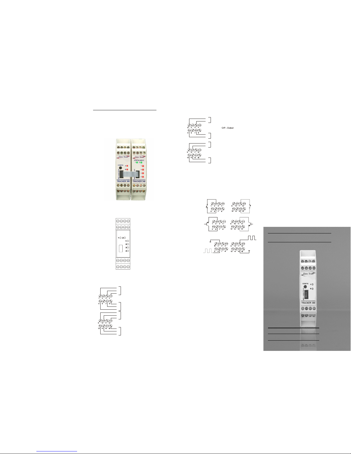
Tracker 340 Expansion Module
1. Introduction
The Tracker 340 expansion module is connected to a Tracker 300 series
instrument via the expansion port. The Tracker 340 is powered by and
configured via the Tracker 300.
2. Connections
The diagram below shows the terminal connection arrangement.
Relay Connections
Logic Connections
3. Connecting the Status Inputs
There are two status (logic) inputs provided on the Tracker 340 expansion
module. The inputs can be used with either voltage free contacts, such as
relay contacts, switches, open collector transitor outputs, or voltage driven.
The inputs are active low, i.e. apply a short circuit between the status input
and status common. The following diagrams illustrate typical applications.
Status Input 1 Status Input 2
Voltage Free
Contacts
Open Collector
TTL Outputs
Voltage Driven
Note: 0V is active
4. Indicators
There are six LEDs on the front panel of the instrument, two green (input)
and four red (output).
Green LED Status Inputs 1 & 2– lit when the respective status input is
active.
Red LED 1, 2, 3 and 4 – programmable LEDs.
5. Specification
Relay Option
Relays 4 off, change over
Rating 1A @ 230V AC, 1A @ 30V DC
Relay isolation Isolated from each other and all other inputs
and outputs
TTL Logic Option
Drivers 4 off, TTL
Rating ±20mA, source or sink
Isolation No isolation
Status Inputs (both options)
Logic inputs 2 off, voltage free or TTL
Protection Reverse diode p rotected
DATA TRACK Process Instruments Ltd
153 Somerford Road
Christchurch, Dorset
BH23 3TY
United Kingdom
TRACKER 300 SERIES
INSTALLATION GUIDE
DATA TRACK
PROCESS INSTRUMENTS
Accuracy Including Lin earisation
Thermocouple Range (
o
C) Worst Case Typical @ 20°C
Type B, Pt30%Rh/ Pt6%Rh 0 to 1820 ±1.0°C ±0.5°C
Type J, Fe/NiCu -210 to 1200 ±1.0°C ±0.5°C
Type K, NiCh/Ni/ Al -270 to 1372 ±1.0°C ±0.5°C
Type T, Cu/CuNi -270 to 400 ±1.0°C ±0.5°C
Type N, Nicrosil- Nisil - 200 to 1300 ±1.0°C ±0.5°C
Type R, Pt13%Rh -Pt -50 to 1767 ± 2.0°C ±1.2°C
Type S, Pt10%Rh-P t -50 to 1767 ±2.0°C ±1.2°C
Accuracy Including Lin earisation
RTD Type Range (
o
C) Worst Case Typical @ 20°C
Pt100 (alpha = 385) -200 to 850 ±0.8°C ±0.4°C
Pt100 (alpha = 392) -270 to 457 ±0.8°C ±0.4°C
1234
57
68
9101112
13 1514 16
C
NO
NC
NC
NO
C
NC
NO
C
C
NO
NC
Relay1
Relay2
Relay3
Relay4
C - Common
NO - Normally Open
NC - Normally Closed
0V
O/P
Logic1
Logic2
Logic3
Logic4
O/P
0V
O/P
0V
0V
O/P
0V
0V
5V
0V
0V
5V
 Loading...