

Page 1
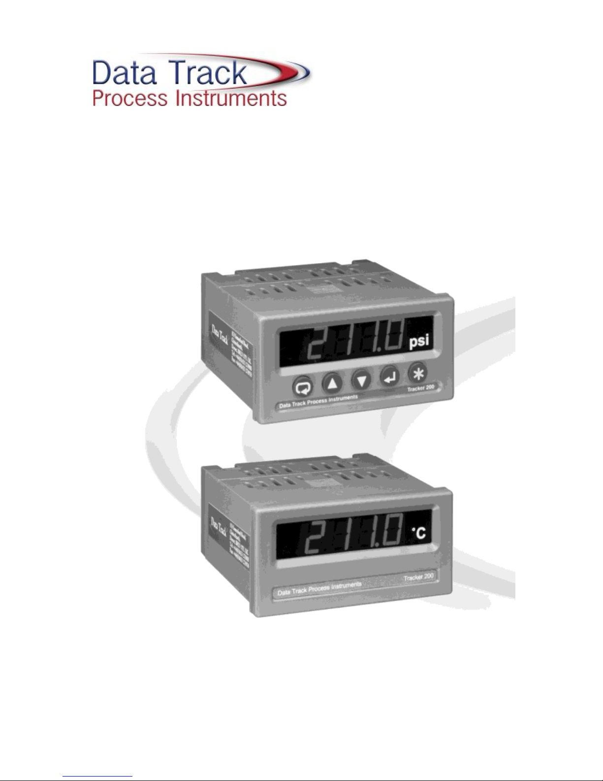
TRACKER 211
Low Cost Panel Indicator
A Budget Priced Universal Input Panel Indicator
for Temperature and Process Measurement
Page 2
Parts Number 20-5110 Issue G
Celebrating 20 years in the design and manufacture of innovative hardware
and software products for the Telecommunication and Process
Measurement Industries.
TRACKER 200 SERIES
Digital Panel Indicator Solutions for:
Displacement - T280, T260, T220, T210 Series
Temperature - T232, T220, T210 Series
Frequency - T280 Series
Totalising - T280 Series
Weighing - T240, T220, T210 Series
Pressure - T250, T232, T220, T210 Series
Encoder - T280 Series
Timing - T280 Series
Flow - T280, T220, T210 Series
Ask your Tracker supplier for full details
© Data Track Process Instruments Ltd. 2000 - 2011
No part of this publication may be reproduced or transmitted in any form or by any
means, electronic, mechanical, photocopying, recording or otherwise, or stored in any
retrieval system of any kind, without the written permission of Data Track Process
Instruments Ltd.
DATA TRACK
PROCESS INSTRUMENTS
153 Somerford Road, Christchurch, Dorset, BH23 3TY
Tel: +44 (0) 1425 271900 Fax: +44 (0) 1425 271978
Email: [email protected]
Page 3

Temperature & Process Measurement Indicators Setup Guide
20-5110 Issue G 1
Contents
Introduction ................................................................................................ 2
Installation ................................................................................................. 3
Connections ............................................................................................... 5
Connecting the Sensor ............................................................................... 6
Powering the Instrument ............................................................................ 7
Operator Functions ..................................................................................... 8
The Setup Menus ....................................................................................... 9
Configuration Menu Map ................................ ................................ ......... 12
Menu Options .......................................................................................... 14
Messages ................................ ................................ ................................ .. 18
Page 4
Temperature & Process Measurement Indicators Setup Guide
2 20-5110 Issue G
Introduction
This Setup Guide describes how to install and configure your instrument.
This instrument is marked with the international
hazard symbol. It is important to read this Setup
Guide before installing or commissioning your panel
meter as it contains important information relating
to safety and Electromagnetic Compatibility EMC.
The instrument provides the following features as standard:
Universal input for mV, mA, volt, thermocouple, RTD and resistance.
1 configurable alarm with relay output.
4 digit bright LED display.
Transducer/transmitter supplies.
<110mm behind panel depth (or 100mm without any options fitted).
The instrument provides the following features as options:
Isolated 4 - 20mA scaleable retransmission output.
Up to 2 additional alarms with relay outputs.
Front panel keypad with function keys.
Page 5

Temperature & Process Measurement Indicators Setup Guide
20-5110 Issue G 3
Installation
To install your instrument, you will need to carry out the following steps:
Apply the engineering units label to the right-hand side of the display
panel. A sheet of labels covering the most commonly used
engineering units is supplied with all units. If the unit you require is
not on the sheet, a blank label is provided on which you can use
LETRASET™.
Install the instrument into a panel.
Make connections to the instrument.
PLEASE NOTE:
Ensure that the power to the instrument is switched off before
carrying out any installation or maintenance work.
It is recommended that all connections to the terminals are made using
ferrules to afford greater reliability and to prevent short circuits
between adjacent terminals.
Avoid installing the instrument close to switch gear, contactors or
motor starters.
Do not place signal and power supply wiring in the same loom.
Use screened cables or wires for all signal/sensor leads with screen
earthed at one point only.
Panel Mounting
The instrument is supplied with an installation kit consisting of a mounting
clamp, a panel sealing gasket and terminal connectors.
Ensure that there is sufficient space behind the instrument panel - the
instrument requires a depth of 100mm (110mm when any options are
fitted) plus enough space to allow safe routing of cables.
To install the instrument:
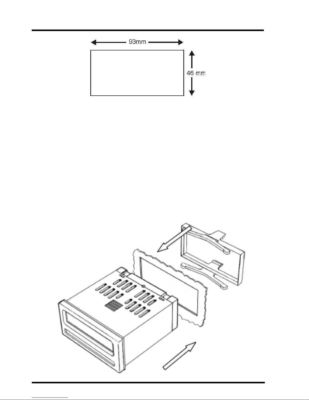
1. Make panel cut-out with the dimensions as shown overleaf. Panel
thickness from 1.5mm to 9.5mm can be accommodated.
Page 6
Temperature & Process Measurement Indicators Setup Guide
4 20-5110 Issue G
2. Fit the rubber seal by slipping it over the unit from the rear of the
box and pushing it forwards until it sits behind the front lip of the
unit.
3. Insert the instrument into the panel from the front, pushing it through
as far as the front lip, to ensure correct seating of the rubber seal
between the panel and the unit.
4. Working from behind the panel, take the mounting clamp, slide over
the rear of the instrument and push forwards.
5. Continue to push the clip forward until the ratchet operates and the
clamp is sufficiently compressed to apply adequate pressure on the
panel.
Page 7
Temperature & Process Measurement Indicators Setup Guide
20-5110 Issue G 5
Connections
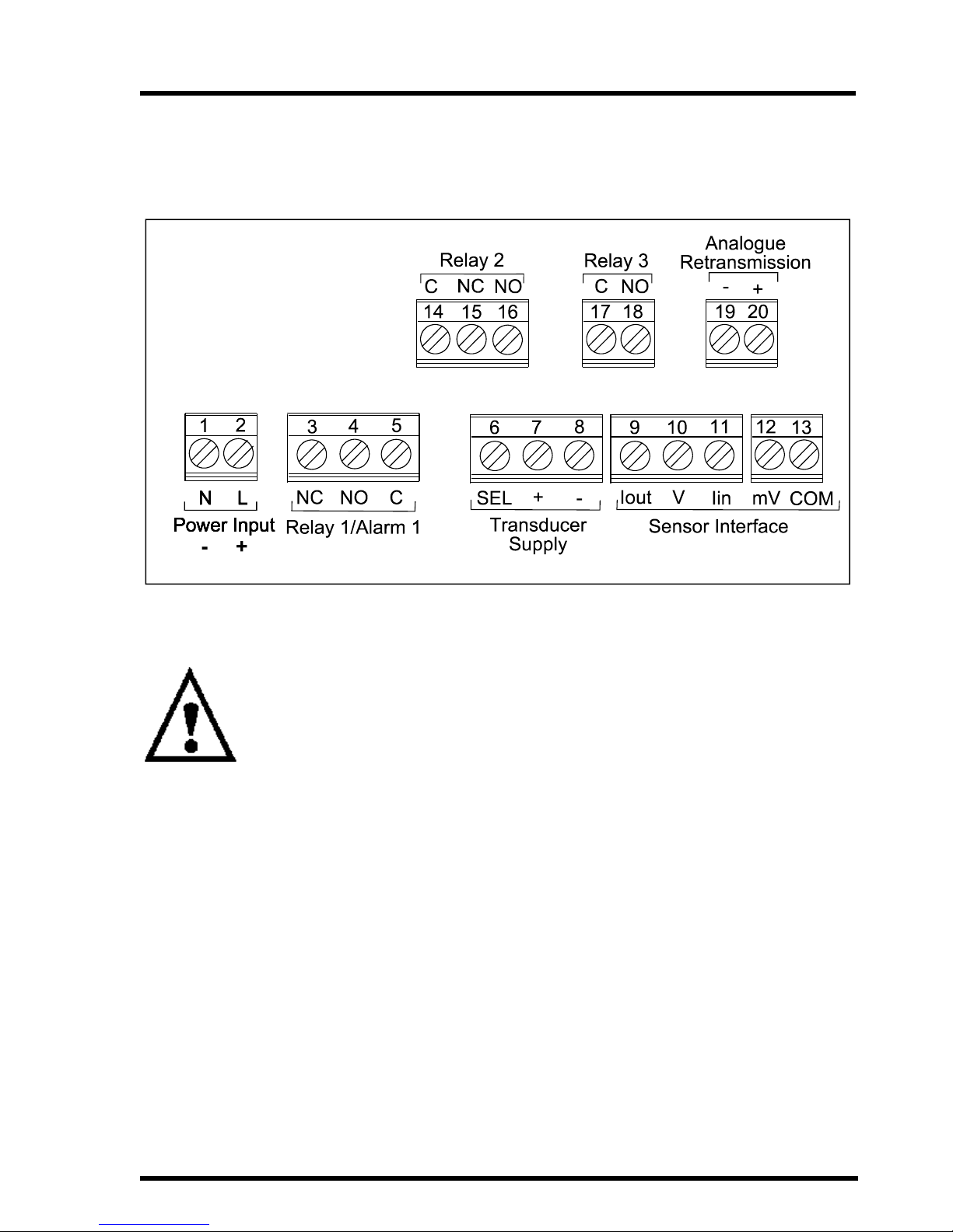
The diagram below shows the rear panel terminal connection arrangement.
Rear Panel Terminal Connections
Ensure the power supply is connected to Terminals 1 & 2 (marked N & L).
Page 8
Temperature & Process Measurement Indicators Setup Guide
6 20-5110 Issue G
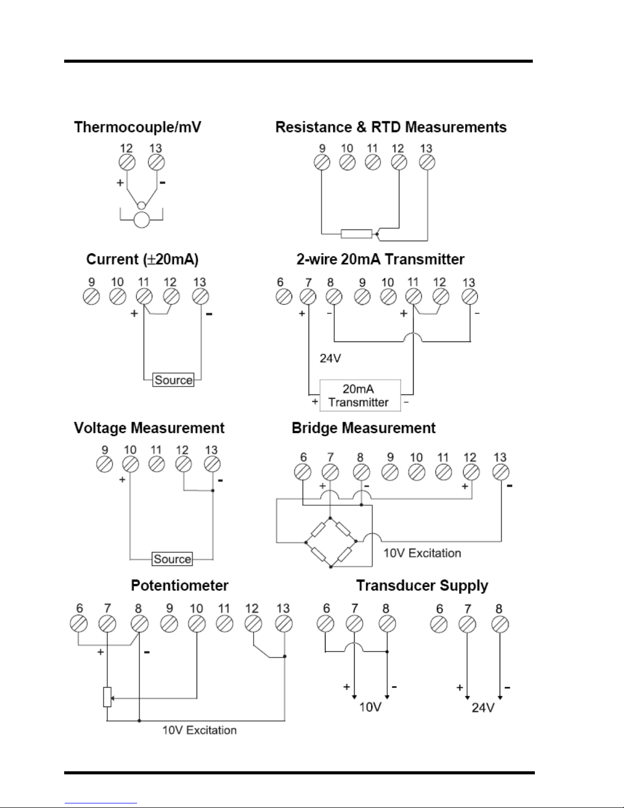
Connecting the Sensor
Page 9
Temperature & Process Measurement Indicators Setup Guide
20-5110 Issue G 7
Powering the Instrument
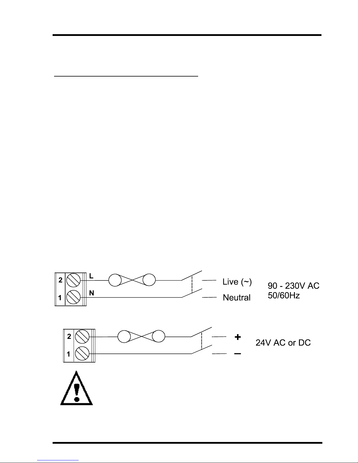
THERE ARE 2 SUPPLY VARIANTS: a mains supply variant and a low
voltage supply variant. The instrument is designed to operate from either
an AC supply with voltages in the range 90 to 230V AC 50/60Hz mains
supply or from a DC supply with voltages in the range 24 to 32V DC (20
to 30V AC) 50/60Hz low voltage supply with a maximum power
consumption of 20VA when all outputs are fully loaded and the display
has all segments illuminated.
The diagrams below show how the instrument should be connected to the
mains supply. Isolation should be provided by a double pole switch and a
time delay 200mA fuse.
WARNING - The instrument is designed for installation in an
enclosure which provides adequate protection against electric shock.
Access to power terminals should be restricted to authorised skilled
personnel only. Application of supply voltages higher than those for
which the instrument is intended may compromise safety and cause
permanent damage.
Recommended Mains Supply Connections
Recommended Low Voltage Supply Connections
BEFORE POWERING UP THE INSTRUMENT,
check the model label on the underside of the
instrument for the supply variant, eg. MAINS OR
LOW VOLTAGE.
Page 10
Temperature & Process Measurement Indicators Setup Guide
8 20-5110 Issue G
Operator Functions
These functions are only available on units which have the front panel
push buttons.
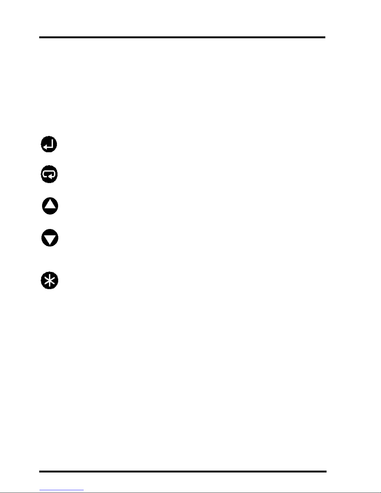
Operator/Configuration Mode - Key Functions
From the normal runtime display:
Enter - Accesses the setup menus.
Next - Scrolls forward through the setup menus.
Up - Function Key 1 (see page 17).
Down - Accesses the alarm setpoint(s). Use the Next Key for
viewing and the Enter Key for editing.
Star - Function Key 2 (see page 17).
NOTE: Units which have the front panel push buttons are externally
configurable. Units which do not have front panel push buttons are
internally configurable (see page 9).
Page 11
Temperature & Process Measurement Indicators Setup Guide
20-5110 Issue G 9
The Setup Menus
Behind the Front Panel
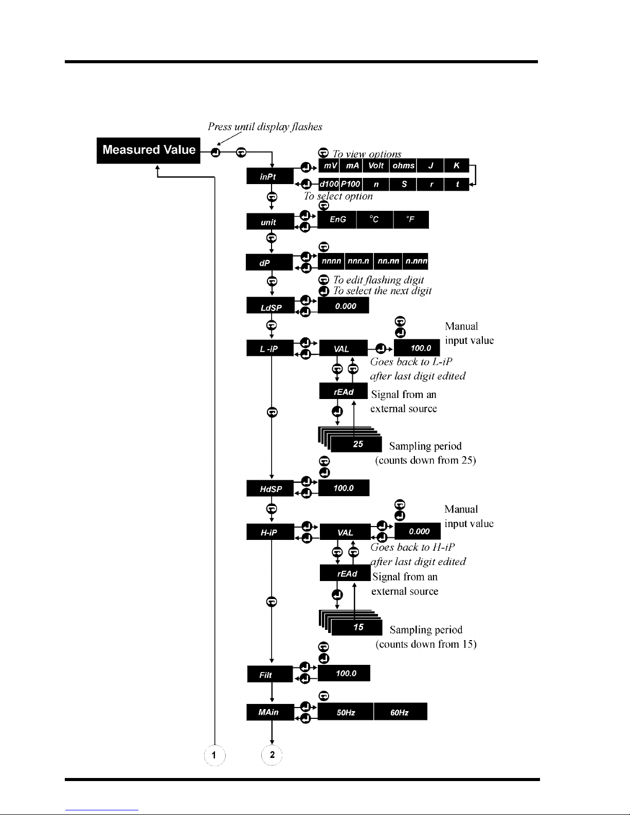
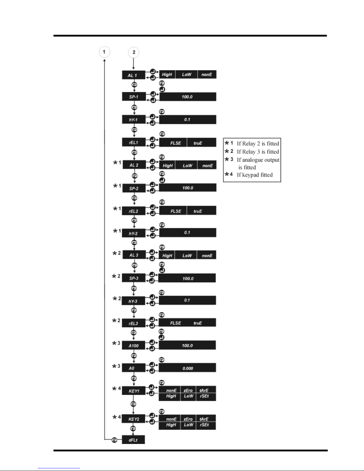
The instrument uses a single level menu structure. The menu system lists
parameters (eg. inPt, unit, dP, etc.), each of which leads to a list of
configurable instrument options (eg. the parameter inPt leads to the
options mV, mA, VoLt etc.).
To enter the setup menus:
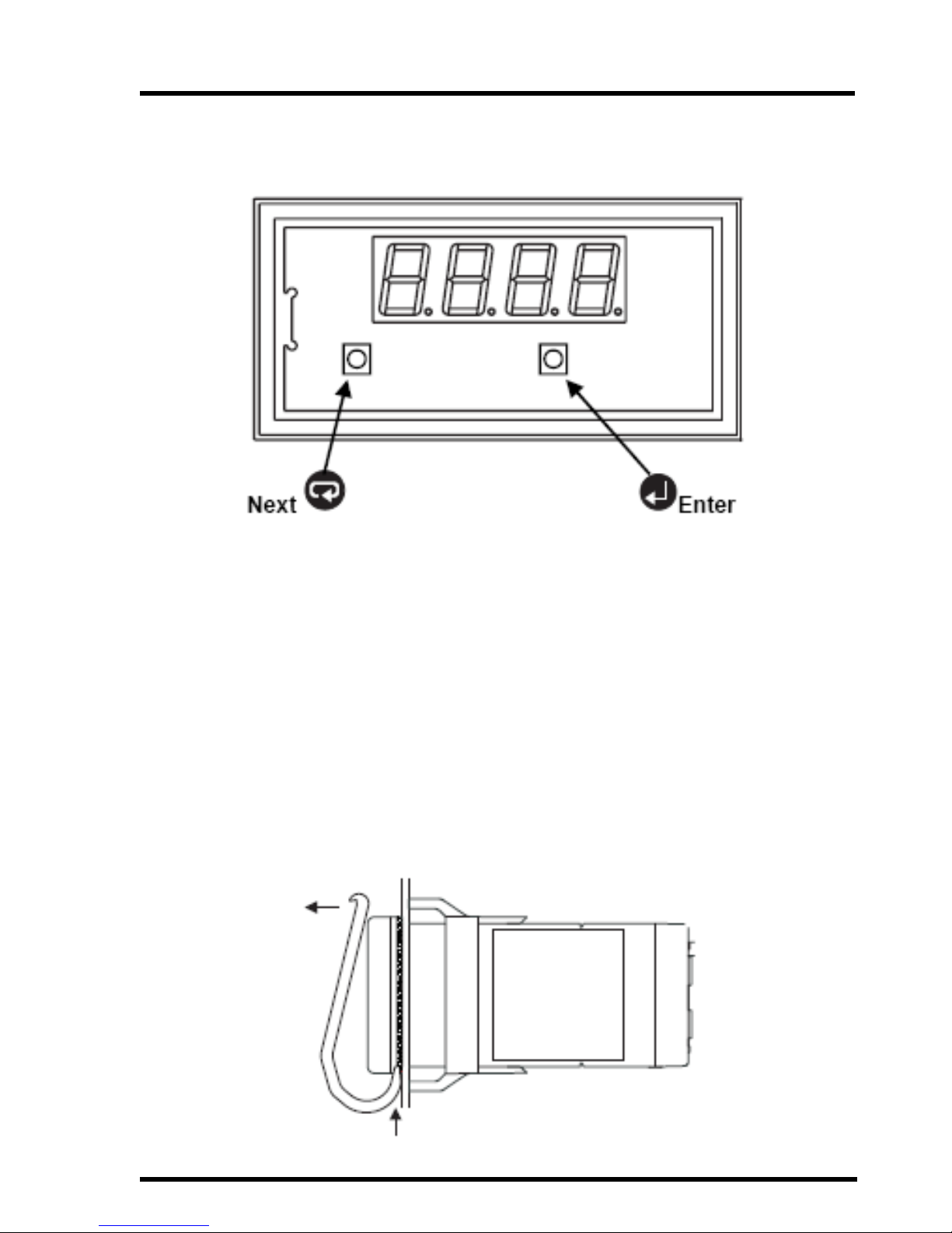
1. Remove the front cover by pushing the extraction tool into the gap
below the bezel and then pulling the tool forward to unclip the bezel
as shown in the diagram below.
Page 12

Temperature & Process Measurement Indicators Setup Guide
10 20-5110 Issue G
Removing the Bezel with the Extraction Tool
2. Press and hold down the Enter Key for approximately 3 seconds
until the display begins to flash.
3. Press the Next Key and the flashing display should be replaced with
the message inPt (the first menu parameter).
4. To cycle through the menu parameters, press the Next Key
repeatedly.
5. To view a menu parameter, press the Enter Key and the current
option for that parameter will be displayed.
6. To cycle through all of the available options for a parameter, press
the Next Key.
7. Press the Enter Key to select the required option.
8. a) Editing a Setting
Some parameters are setup by selecting from a list of options
(eg. the parameter unit has 3 options: oC, oF and EnG).
The following example will show you how to edit a parameter.
We will change the decimal places (labelled dP) from 1 to 2.
With the unit displaying the measured value, press and
hold down the Enter Key for approximately 3 seconds
until the display begins to flash.
Press the Next Key and the flashing display should be
replaced with the message inPt (the first menu parameter).
Press the Next Key repeatedly until dP is displayed.
Press the Enter Key and nnn.n will be displayed.
Press the Next Key and the decimal point will move and
nn.nn will be displayed.
Press the Enter Key to save this setting and exit. When the
Enter Key is pressed, the display will return to the menu
parameter, ie. dP.
Press the Next Key repeatedly to scroll through the rest of
Page 13

Temperature & Process Measurement Indicators Setup Guide
20-5110 Issue G 11
the menu parameters until the measured value display is
restored.
b) Editing a Value
Other parameters are changed by editing a value (eg. the
parameter HdSP has a default numeric value of [100.0]).
Press the Next Key to edit the flashing digit and the Enter
Key to select the next digit for editing.
The following example will show you how to edit a numeric
value. We will change the high display value (labelled HdSP).
With the unit displaying the measured value, press and
hold down the Enter Key for approximately 3 seconds
until the display begins to flash.
Press the Next Key and the flashing display should be
replaced with the message inPt (the first menu parameter).
Press the Next Key repeatedly until HdSP is displayed.
Press the Enter Key and 100.0 will be displayed (with the
least significant digit flashing).
Press the Next Key to scroll through digit values 0 to 9
and edit the least significant digit.
To move to the next most significant digit, press the
Enter Key and the digit will flash.
Repeat the previous 2 steps until the left most significant
digit is flashing.
Press the Next Key to scroll through digit values -1, - and
0 to 9.
If the value allows the dP position to be moved, the dP
will flash. To move the dP position, use the Next Key.
Press the Enter Key to save this value and exit. When the
Enter Key is pressed and the left most significant digit is
flashing, the display will return to the menu parameter, ie.
HdSP.
Press the Next Key repeatedly to scroll through the rest of
the menu parameters until the measured value display is
restored.
Page 14
Temperature & Process Measurement Indicators Setup Guide
12 20-5110 Issue G
Configuration Menu Map
Page 15
Temperature & Process Measurement Indicators Setup Guide
20-5110 Issue G 13
Page 16
Temperature & Process Measurement Indicators Setup Guide
14 20-5110 Issue G
Menu Options
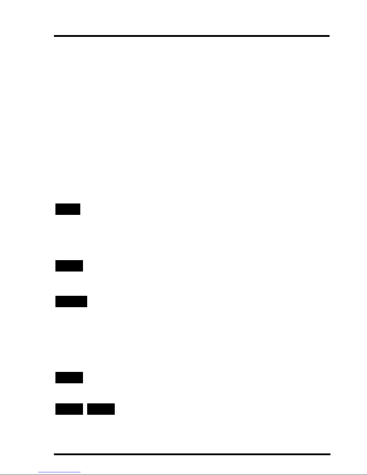
Input Default: mV
Allows the input type and range to be defined. There are 12 ranges
for measurement available. When a thermosensor range is selected, ie. J,
K, t, r, S, n or RTD, the instrument will automatically set the appropriate
scaling in oC. Note: Due to the limitations of a 7-segment display, the mA
option is displayed as na, the mV option is displayed as nu and the
ohms option is displayed as ohns.
Engineering Units Default: Eng
Allows the user to define the units of measurement to be displayed
in oC, oF and Eng (linear engineering units).
Decimal Position Default: 1
Defines the position of the decimal point for the display; 0 or 1 for
thermocouples/RTD and 0 to 3 for process inputs.
High and Low Display Values Default: Low = 000.0, high = 100.0
The low display value LdSP is used for scaling purposes
when combined with the other scaling parameters L-iP, HdSP, and H-iP.
These 4 parameters can scale the measured input to any engineering units
as long as the relationship between the displayed units is linear. LdSP is
used to define the value to be displayed for an input defined by L-iP.
HdSP is used to define the value to be displayed for an input defined by
H-iP.
High and Low Input Values
Correspond to the signal output values from the sensor
which will cause the instrument to display the values set as LdSP and
HdSP. L-iP and H-iP can be input in mV, V, mA etc.
There are 2 methods of setting the low and high input
values, either by manually entering a signal value using the VAL option or
by sampling the sensor output using the rEAd option. Values entered
manually are entered in the same way as other numeric values (see
inPt
unit
dP
L-iP
HdSP
LdSP
H-iP
VAL
rEAd
Page 17
Temperature & Process Measurement Indicators Setup Guide
20-5110 Issue G 15
Editing a Value page 11). The value to be entered will usually be
supplied with the data accompanying your sensor. However, if it is not
available, the output from the sensor may be rEAd from an external
source by the instrument. When performing a rEAd input as part of the
scaling process, the sensor must have the corresponding physical value
applied. This may be pressure, weight, temperature etc. The instrument
will sample the output from the sensor and save this as the L-ip and H-iP
scaling parameters.
A example of scaling: 0 - 100 mV = 0 -1000 (psi)
LdSP = 0 L-iP = 0 (mV)
HdSP = 1000 H-ip = 100.0 (mV)
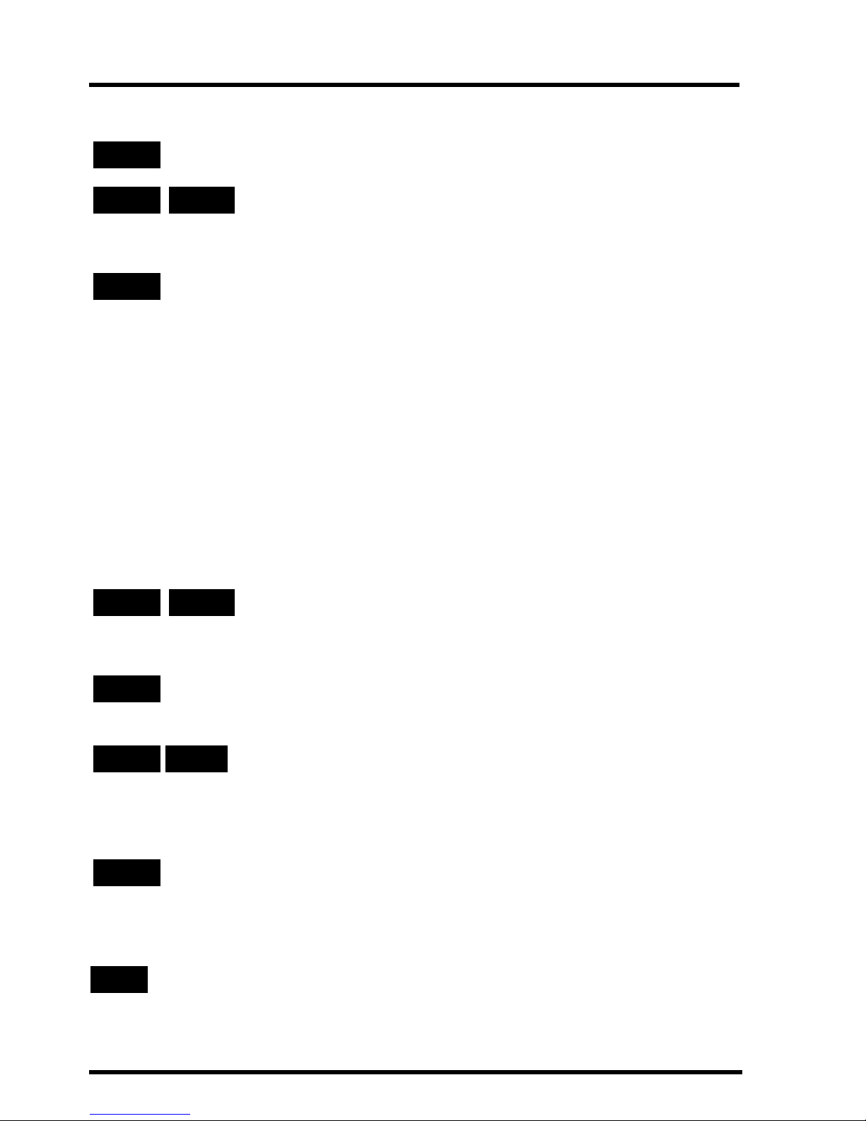
Display Filtering Default: 000
This parameter is used to apply a digital filter to the display value.
The filter is defined in seconds which approximate to the time constant.
This parameter would be used to damp out any effects from noisy signals.
Mains Frequency Default: 50Hz
Set to the mains frequency dependent on the local mains supply.
Alarm Messages Display Default: On
Enables display alarm messages when set to on or disables
messages when set to oFF.
NOTE: Alarm 3 has the highest priority for messages and Alarm 1 has the
lowest.
Alarm 1 Mode Default: None
Defines whether Alarm 1 is disabled when to set to nonE or
operates as a high or low alarm.
As Alarm 1 if Alarms 2 and 3 fitted.
Filt
MAin
AdSP
AL 1
AL 2
AL 3
Page 18
Temperature & Process Measurement Indicators Setup Guide
16 20-5110 Issue G
Alarm Setpoint 1 Default: 100.0
Defines the alarm setpoint for Alarm 1 in display units.
As Alarm Setpoint 1 if Alarms 2 and 3 are fitted.
Hysteresis 1 Default: 0.1
Specifies the size of a band around an Alarm Setpoint within
which the measured value may fluctuate without the alarm state changing.
It is in the same engineering units as the displayed value and the Setpoint.
The hysteresis value defines both the on and oFF hysteresis.
on hysteresis: For a high alarm it is the value (in engineering units) above
the setpoint beyond which the alarm is turned on. For a low alarm, it is the
measured value below the setpoint beyond which the alarm is turned on.
oFF hysteresis: For a high alarm it is the value (in engineering units)
below the setpoint beyond which the alarm is turned off. For a low alarm,
it is the measured value above the setpoint beyond which the alarm is
turned off.
The default hysteresis value for all alarms is 0.1.
As Hysteresis 1 if Alarms 2 and 3 are fitted.
Relay 1 Default: True
Defines the operation of Relay 1, which can be in either the
energised alarm state (truE) or the de-energised alarm state (FLSE).
As Relay 1 if Alarms 2 and 3 are fitted.
A100 Default: 100.0
Defines the display value which corresponds to 20mA or 10V
from the optional analogue retransmission.
A0 Default: 0.0
Defines the display value which corresponds to 4mA or 0V from
the optional analogue retransmission.
A0
A100
rEL2
rEL3
rEL1
SP-2
SP-3
SP-1
hY-1
hY-2
hY-3
Page 19

Temperature & Process Measurement Indicators Setup Guide
20-5110 Issue G 17
Key 1
On units fitted with the front panel buttons, the following
functions may be assigned to either or both function keys: zero, tare,
display high (maximum) or low (minimum) value since last reset or reset
of the high and low values to the current measured value. See Default
(below) for related information.
Key 2
As for Key 1.
Default Default: Off
Allows the instrument to be returned to its factory supplied
setup.
NOTE: On a 211 with front panel keys, defaulting the unit removes the
Key1 and Key2 options from the setup menu. Immediately after defaulting
the unit, press either one of the function keys (up-arrow or star) to restore
these options.
dFLt
KEY2
KEY1
Page 20
Temperature & Process Measurement Indicators Setup Guide
18 20-5110 Issue G
Messages
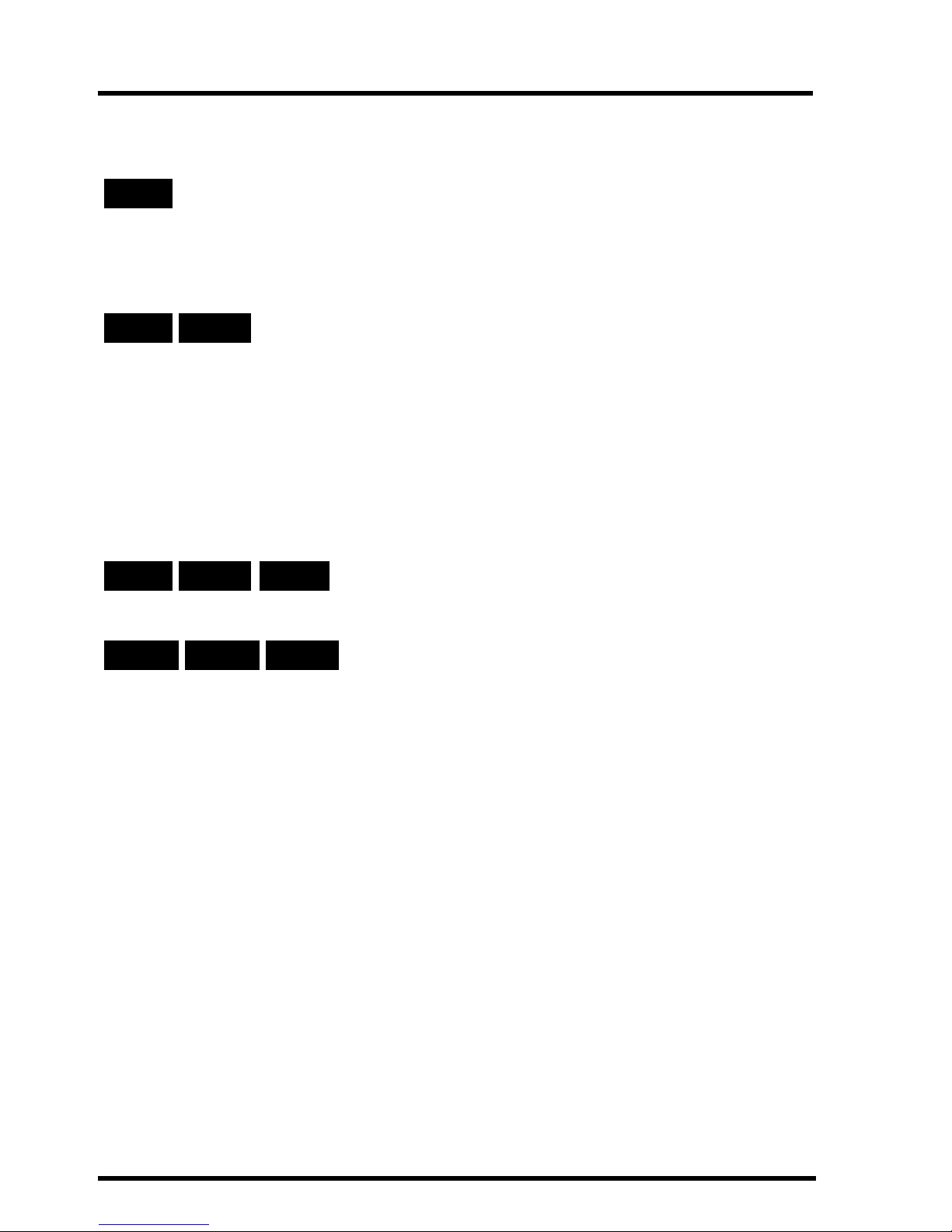
The input circuit, when measuring mV, thermocouple or RTD, has
detected an open circuit sensor connection. When a sensor break is
detected by the instrument, the measured value will be forced upscale
causing any high alarms to be activated.
Displayed when the measured value goes out of its
allowed range, either outside the normal range of the connected
thermosensor or the maximum/minimum display range for the decimal
places set.
Alarm Messages
Alarm messages are 3 letters followed by the alarm number. The codes
are:
High alarm. Eg. HiA3 indicates high Alarm 3
has been activated.
Low alarm.
NOTE: Alarm 3 has the highest priority for messages and Alarm 1 has the
lowest.
LoA1
LoA2
LoA3
HiA1
HiA2
HiA3
undr
oVEr
brk
 Loading...