

Page 1
1
Page 2

2
TABLE OF CONTENTS
GENERAL INFORMATION...................................................................................................................... 4
COPYRIGHT ................................................................................................................................................ 4
NOTICES AND CLASSIFICATIONS ................................................................................................................ 4
CONTACT US..............................................................................................................................................4
PRECAUTIONS FOR THE RAID SYSTEM............................................................................................ 5
GENERAL PRECAUTIONS.............................................................................................................................5
RAID SYSTEM PRECAUTIONS .................................................................................................................... 5
INTRODUCTION........................................................................................................................................ 6
FEATURES................................................................................................................................................... 6
SYSTEM REQUIREMENT..............................................................................................................................7
MAC...................................................................................................................................................... 7
OPTIONAL ACCESSORIES ............................................................................................................................ 7
PACKAGE CONTENTS.................................................................................................................................. 8
SYSTEM VIEWS......................................................................................................................................... 9
FRONT VIEW............................................................................................................................................... 9
REAR VIEW ................................................................................................................................................ 9
TOP & COVER VIEW (EXPOSED)................................................................................................................10
INSERTING/REPLACING THE HARD DRIVES IN THE RAID SYSTEM......................................11
FASTEN THE HDD SMARTGUIDER KIT ONTO THE HARD DRIVE ..............................................................12
PLACE THE HDD SMARTGUIDER KIT INSIDE THE RAID SYSTEM ............................................................15
CONNECTING THE RAID SYSTEM TO A HOST COMPUTER.......................................................17
NUMBER OF HARD DRIVE/SSD SUPPORTING EACH RAID MODE............................................19
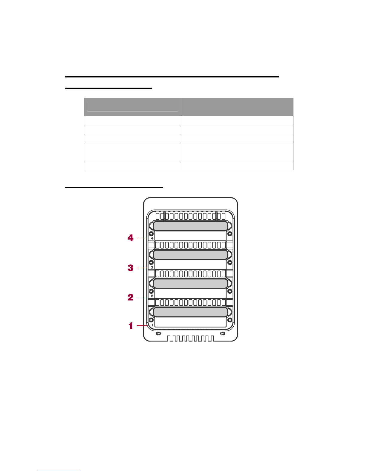
DISK SLOT NUMBER...............................................................................................................................19
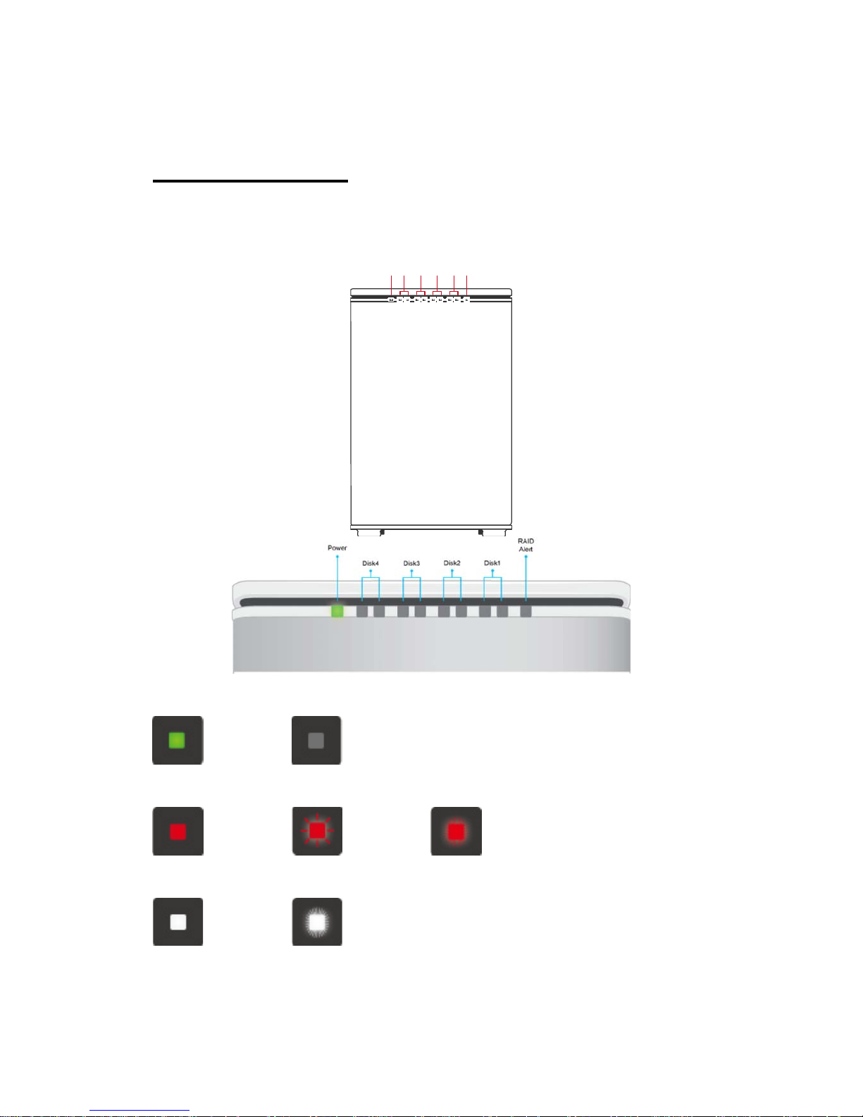
LED INDICATORS....................................................................................................................................20
GREEN: ON / OFF.......................................................................................................................................20
RED: ON / BLINK / FLASH ..........................................................................................................................20
WHITE: ON / FLASH...................................................................................................................................20
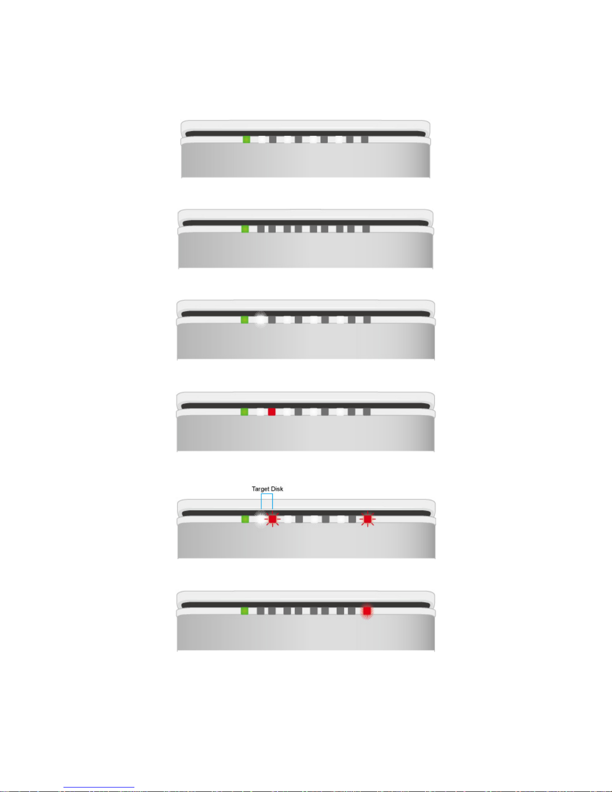
ALL DISKS: INSERTED / DETECTED............................................................................................................21
ALL DISKS: NOT INSERTED / DETECTED...................................................................................................21
ALL DISKS: DISK 4 DATA ACCESS ONLY.................................................................................................21
ALL DISKS: DISK 4 ERROR ONLY............................................................................................................21
ALL DISKS: DISK 4 REBUILD ONLY.........................................................................................................21
FAN: ERROR ..............................................................................................................................................21
DAISY CHAIN: CONNECTING MULTIPLE DEVICES......................................................................22
SAFE REMOVAL OF THE RAID SYSTEM...........................................................................................22
SSD SMARTGUIDER KIT........................................................................................................................23
SSD SMARTGUIDER KIT: PACKAGE.....................................................................................................23
SSD SMARTGUIDER KIT: SSD COMPATIBILITY...................................................................................23
SSD SMARTGUIDER KIT: INSTALLATION.............................................................................................24
RAID MASTER...........................................................................................................................................26
RAID MASTER: INSTALLATION..........................................................................................................26
INSTALLATION FOR MAC.................................................................................................................26
Page 3

3
RAID MASTER: GUI.................................................................................................................................30
INFORMATION:...................................................................................................................30
CONFIGURATIONS:............................................................................................................30
SETTINGS:............................................................................................................................30
NOTIFICATIONS:.................................................................................................................30
LOGS:....................................................................................................................................30
FIRMWARE:..........................................................................................................................30
RAID MASTER: FEATURES...................................................................................................................31
INFORMATION......................................................................................................................................31
Device Information:.......................................................................................................... .. ...31
RAID & Disk Information:....................................................................................................31
Disk Information: ..................................................................................................................32
RAID CONFIGURATIONS:....................................................................................................................33
SETTINGS:..............................................................................................................................................33
NOTIFICATIONS:...................................................................................................................................34
EVENT LOG:...........................................................................................................................................34
FIRMWARE INFORMATION................................................................................................................35
RAID MASTER: OPERATION................................................................................................................36
RAID CONFIGURATIONS: SET UP A NEW RAID SET ......................................................................36
RAID CONFIGURATIONS: DELETE AN EXISTING RAID SET........................................................39
RAID CONFIGURATIONS: REBUILD A RAID SET............................................................................41
GLOSSORY.................................................................................................................................................44
LED INDICATORS....................................................................................................................................44
POWER LED X 1........................................................................................................................................44
RAID ALERT LED X 1 ............................................................................................................................44
DISK LED X 8 ..........................................................................................................................................44
RAID MASTER...........................................................................................................................................45
POPUP WINDOWS.................................................................................................................................45
REBUILD.................................................................................................................................................47
RAID MODES.............................................................................................................................................47
RAID 0 (STRIPING) ...................................................................................................................................48
RAID 1 (MIRRORING) ...............................................................................................................................48
RAID 1+0 .................................................................................................................................................49
JBOD (NONE RAID).................................................................................................................................49
HYPERDUO: CAPACITY AND SAFE.............................................................................................................50
APPENDIX: SPECIFICATIONS..............................................................................................................51
Page 4

4
GENERAL INFORMATION
Copyright
V8 Copyright © 2013 Data Watch Technologies Co., Ltd. All rights reserved.
DataTale and DataTale logo are the trademarks of Data Watch Technologies Co.,
Ltd. No part of DataTale brand products and materials may be reproduced,
stored in a retrieval system, or transmitted in any form or by any means
(electronic, mechanical, photocopying, recording or otherwise), without the prior
written consent of Data Watch Technologies Co., Ltd. Thunderbolt
TM
and the
Thunderbolt
TM
logo are trademarks of Intel Corporation in the United States and
other countries.
The product information provided in this user’s manual is subject to change
without prior notice and does not represent a commitment on behalf of the
vendor. The vendor assumes no liability or responsibility for any errors that may
appear in this manual. Firmware, software, images, and descriptions may vary
slightly from actual products.
Notices And Classifications
FCC-B Radio Frequency Interference Statement
This device complies with Part 15 of the FCC rules. Operation is subject to the
following two conditions:
This device may not cause harmful interference.
This device must accept any interference received, including interference that
may cause undesired operation.
This equipment has been tested and found to comply with the limits for a Class
B digital device, pursuant to Part 15 of the FCC rules. These limits are designed
to provide reasonable protection against harmful interference when the
equipment is operated in a commercial environment. This equipment generates
uses and can radiate radio frequency energy and, if not installed and used in
accordance with the instruction manual, may cause harmful interference to radio
communications.
Contact Us
We are committed to offer economical, high-quality connectivity and storage
enclosure solutions to the market. Any questions, inquiries or comments are
highly welcomed. For the latest version of the User Manual & Technical Support,
please go to our website at www.datawatchtech.com
. To enhance excellent
quality service, please complete the Product Registration on our website.
Data Watch Technologies Co., Ltd.
3F, No. 60, Lane 321, Yang Guang St., Nei Hu, Taipei 114 Taiwan
Tel: +886-2-8797-8868 Fax: +886-2-8797-4801
Email: [email protected]
Page 5

5
PRECAUTIONS FOR THE RAID SYSTEM
General Precautions
¾ The main circuit board of the RAID System is susceptible to static
electricity. Proper grounding is required to prevent electrical
damage to the RAID System or other connected devices, including
the host computer. Always place the RAID System on a smooth
surface and avoid all dramatic movement, vibration and percussion.
¾ Do NOT place the RAID System close to magnetic devices (such
as a mobile phone), high-voltage devices (such as a hair dryer), or
near a heat source (such as on the dashboard of a car or any place
where it will be exposed to direct sunlight).
¾ Use only the power supply cable provided with the RAID System.
¾ Do NOT attempt to service this RAID System yourself. Please
contact Technical Support in regards to any parts other than the
ones already mentioned in the Installation Section of this User’s
Manual.
¾ Do NOT block the ventilation. Proper airflow is required to ensure
reliable operation and to prevent overheating.
¾ Do NOT allow water to enter the RAID System.
¾ Do unplug the RAID System from the electrical outlet when not in
use to provide an ecological friendly environment.
RAID System Precautions
¾ Installation of RAID MASTER software in the host computer is
required for proper operation.
¾ Installation of additional equipment in the host computer may be
required. Visit our website at www.datawatchtech.com
to download
the latest product information updates.
¾ Any loss, corruption, or destruction of data is the sole
responsibility of the user of the RAID System. Under no
circumstances will the manufacturer be held liable for the
recovery or restoration of any data.
Page 6

6
INTRODUCTION
Thank you for purchasing the DataTale SMART 4-Bay Thunderbolt
TM
RAID
System. The RAID System with Thunderbolt
TM
connection and RAID MASTER
(Graphic User Interface) provides up to 10Gbps of access/transfer speeds along
with substantial storage capacity and distinctive RAID configuration options in a
desktop storage device. The RAID MASTER allows easy configuration of RAID
Modes*: JBOD (None RAID), RAID 0 (Striping), RAID 1 (Mirroring), RAID 1+0,
and HyperDuo (Capacity/Safe).
Please thoroughly read and follow the instructions provided in this manual.
Failure to do so may result in damage to the RAID System, and any or all of the
connected devices.
Features
Compatible with SATA hard drives and solid-state drives, up to 6 Gbps
Connects via two (2) Thunderbolt
TM
ports (up to 10Gbps of transfer rates)
Provides multiple RAID tasks* for effective storage management: JBOD
(None RAID), RAID 0 (Striping), RAID 1 (Mirroring), RAID 1+0, and
HyperDuo (Capacity/Safe)
Compatible with Disk Utility (Apple) and configurable as a “Fusion Drive”
Supports Rebuild under RAID 1, and RAID 1+0
Compatible with Time Machine (Apple) for backups & file protection
Provides multiple devices with increased speed and flexibility via Daisy
Chain (Up to six Thunderbolt
TM
-compatible devices/displays)
Configures RAID modes easily using RAID MASTER (GUI)
Monitors System status via LED indicators or RAID MASTER (GUI)
Features effortless yet trayless hard drive/SSD hot swap or hot plug via
SmartGuider*
Dissipates heat efficiently with aluminum housing
Maximizes airflow with two silent fans, SmartGuider* design, and well-
matched mechanical design
Additional RAID modes and features, along with the latest support and troubleshooting information, can be found on our website.
SmartGuider is a trayless device that utilizes the simplicity of a handle and
screws. The integrated handle is attached onto the hard drive (or SSD inside a
SSD Bracket) with auto-limiting segmented screws. Then, the entire HDD/SSD
SmartGuider Kit can be slide into the RAID System by aligning the screws with
its specially designed guides. This enables flexibility for easy hard drive/SSD
removal and insertion.
Page 7
7
System Requirement
To use the RAID System, the minimum system configuration in the host
computer requires the following:
MAC
M acintosh/ Int el i7 or faster processor
1G of RAM or higher
Mac OS X 10.7 or higher
Chrome 18, FireFox 11, Safari 5.1, Opera 11.61, IE 9 or higher
One available ThunderboltTM port
Time Machine Compatible
3.5/2.5-inch SATA-compatible hard drive and/or 2.5-inch SSD are required for
the RAID System. Once the hard drive and/or SSD are formatted, the actual
available storage capacity can vary depending on the selected operating
environment (normally 5-10 % less).
Optional Accessories
SSD SmartGuider Kit (Retail package sold separately)
ThunderboltTM Cable (check your dealer to see if it is included in the
package or sold separately)
Due to restrictions of each individual SSD's controller and user's host system,
not all the SSDs are compatible when utilized with the RAID System. Please see
SSD SmartGuider Kit Section for more information.
Page 8
8
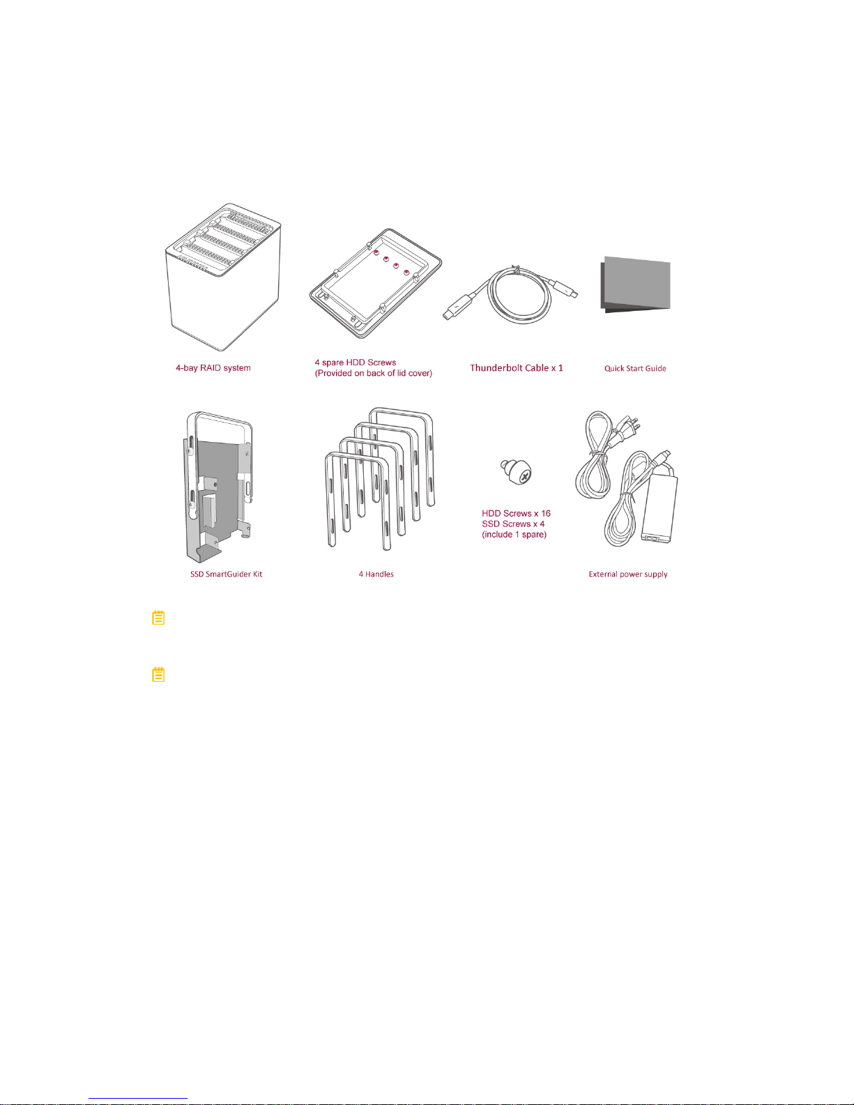
Package Contents
Please keep all package contents and packaging material in the event that the
product must be returned.
Please go to our websites for the most updated information and resources,
including RAID MASTER and User’s Manual. http://www.data-tale.com;
http://www.datawatchtech.com
Page 9
9
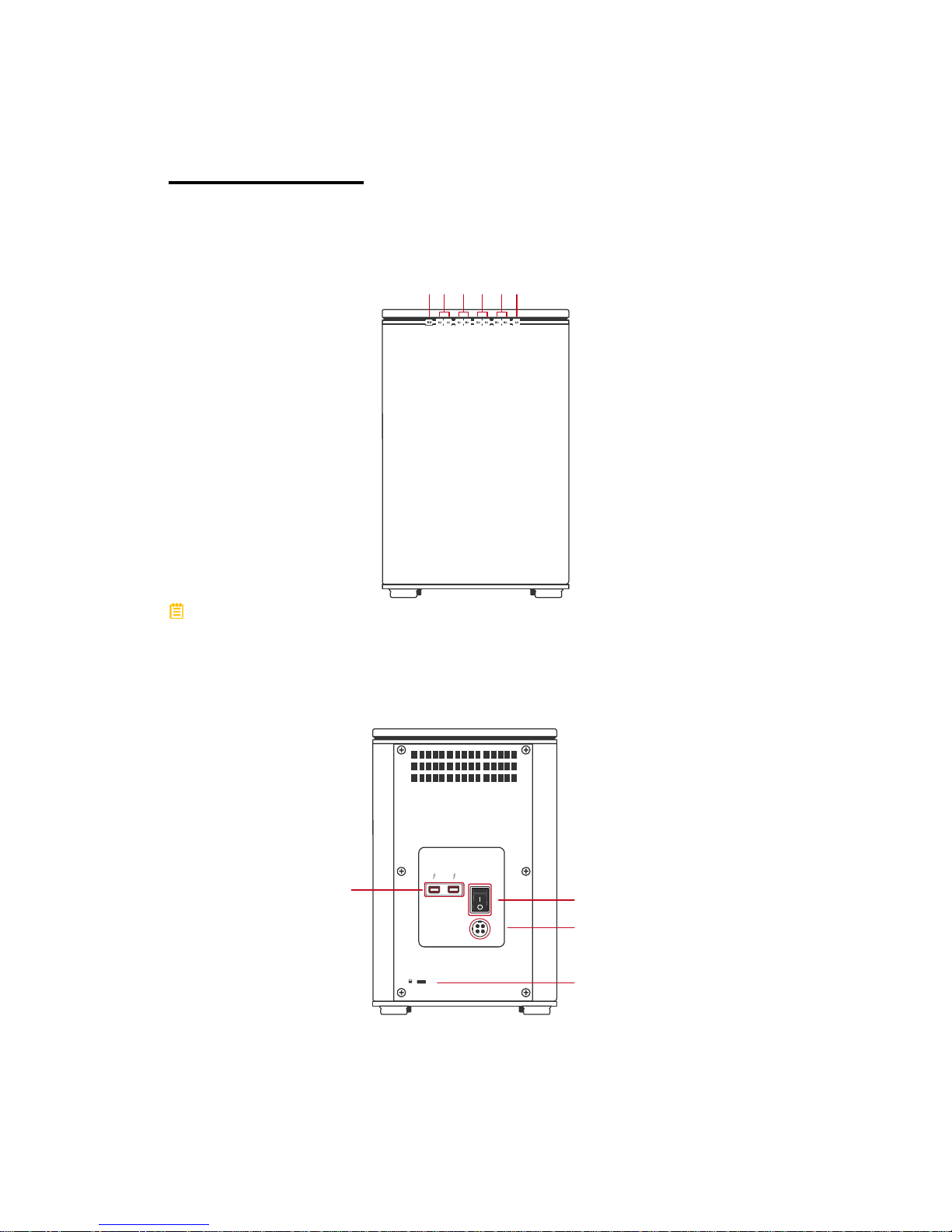
SYSTEM VIEWS
Front View
Power
Disk 4
Disk 3
Disk 2
Disk 1
RAID Alert
The status indication of each LED indicator is listed under the LED
INDICATORS section.
Rear View
DC IN
Thunderbolt
Port
Power Switch
DC IN
Lock Port / Slo
t
Page 10
10
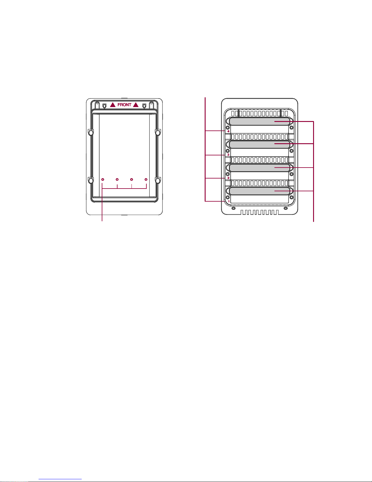
Top & Cover View (Exposed)
Disk Slots (indicate Disk1 through Disk 4)
Handles
4 Spare HDD Screws
Page 11
11
INSERTING/REPLACING THE HARD DRIVES IN
THE RAID SYSTEM
To assemble the RAID System, please follow the steps listed in the instructions
below:
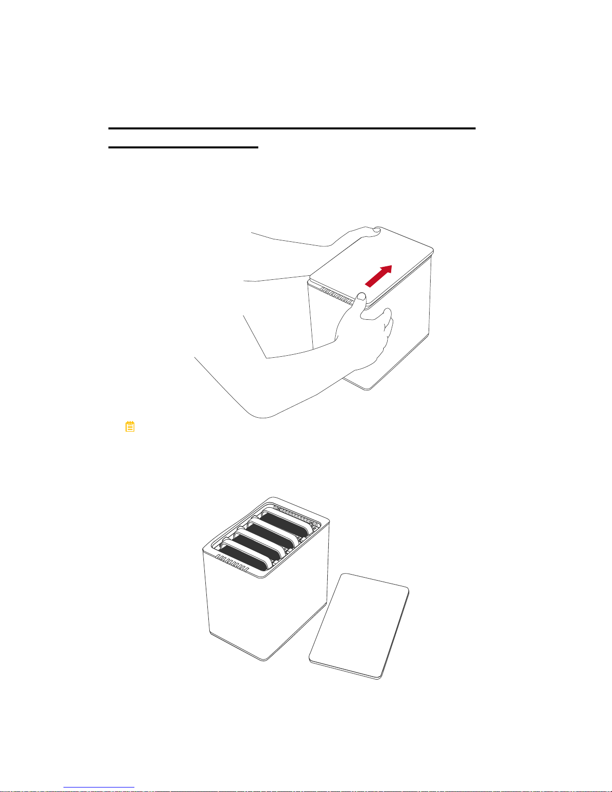
1. Place the RAID System with its Front View facing you. Position both hands
on the top lid, one in the front and one in the back. Simultaneously, push the
lid in the direction away from you, front to back, using your thumbs.
A “click” sound would indicate release of the top lid’s security clasp.
2. Lift the top lid up to remove and expose the Top View (or Disk Slots).
Remove the Handles from the RAID System itself and locate the HDD Screws
in the packaging box.
Page 12
12
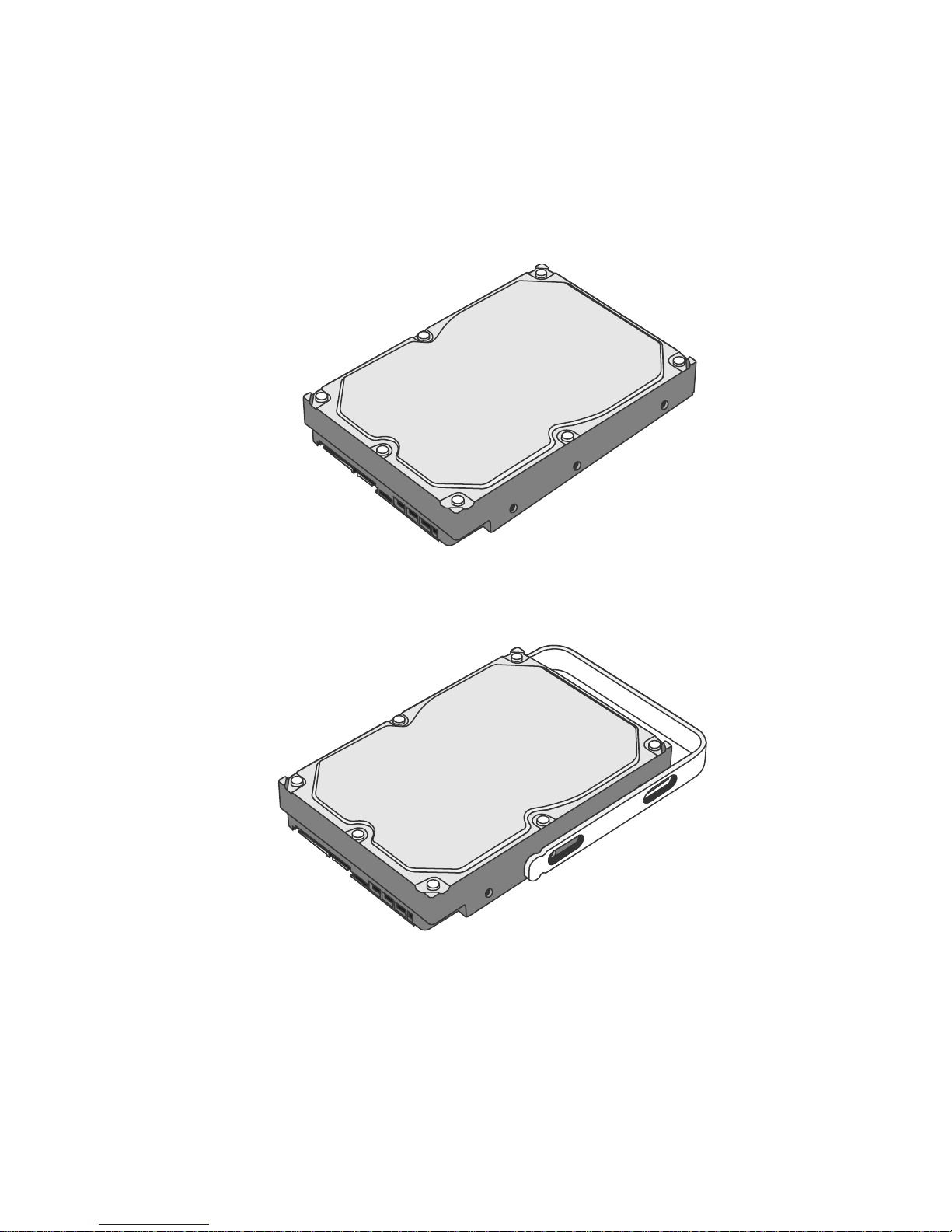
Fasten The HDD SmartGuider Kit Onto The Hard Drive
3. Place the hard drive with the metal cover side facing up and ensure that the
interface connectors are oriented toward your left side.
Connectors
4. Position the Handle to the hard drive end, which is facing away from the
interface connectors, and align it with the HDD Screw hole openings.
Connectors
Page 13
13
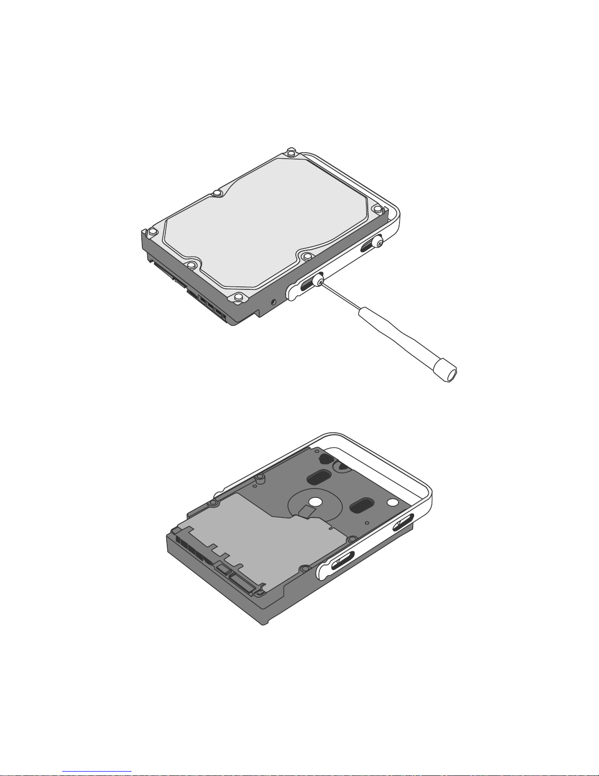
5. Fasten the Handle onto the hard drive by inserting and tightening the HDD
Screws, the left one first, then the right one.
Left
Right
6. Now, flip the hard drive so it is facing you with the PCBA (Printed Circuit
Board) on top and the unfasten Handle side facing you.
Page 14
14
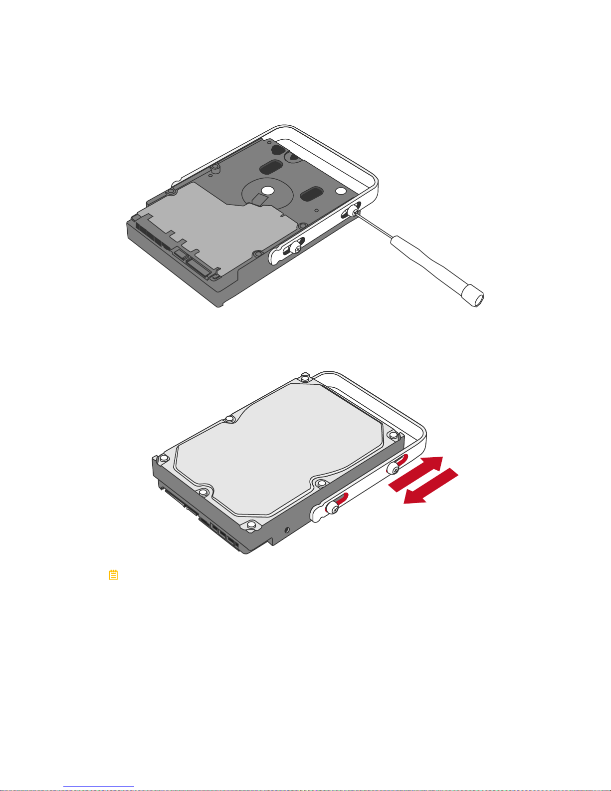
7. Insert and tighten the HDD Screws, the left one first, then the right one.
Left
Right
8. Finally, test sliding the Handle to make sure that the holes glide smoothly on
the HDD Screw guides and the HDD SmartGuider Kit is completed! Repeat
the same procedures for rest of the hard drive(s) if necessary.
The auto-limiting segmented screws are designed to prevent the hard drives
or/and the handles from damages due to over-tightening. Furthermore, this
design makes the handle slide easily without any tightness.
Page 15

15
Place The HDD SmartGuider Kit Inside The RAID System
9. Hold the HDD SmartGuider Kit with its metal cover side facing you and the
Handle attached in the upward position.
If the HDD SmartGuider Kit is inserted on its reverse side, the SmartGuider
System would not be able to align and the HDD SmartGuider Kit cannot be
inserted.
10. Align the Handle with the guide rails and slide the HDD SmartGuider Kit into
the indicated Disk Slot. Firmly push downward until a “thump” sound is heard.
Repeat the same procedures for rest of the HDD SmartGuider Kit(s).
In most cases, you would need to firmly push the HDD SmartGuider Kit to
a close until a “thump” sound is heard.
Page 16
16
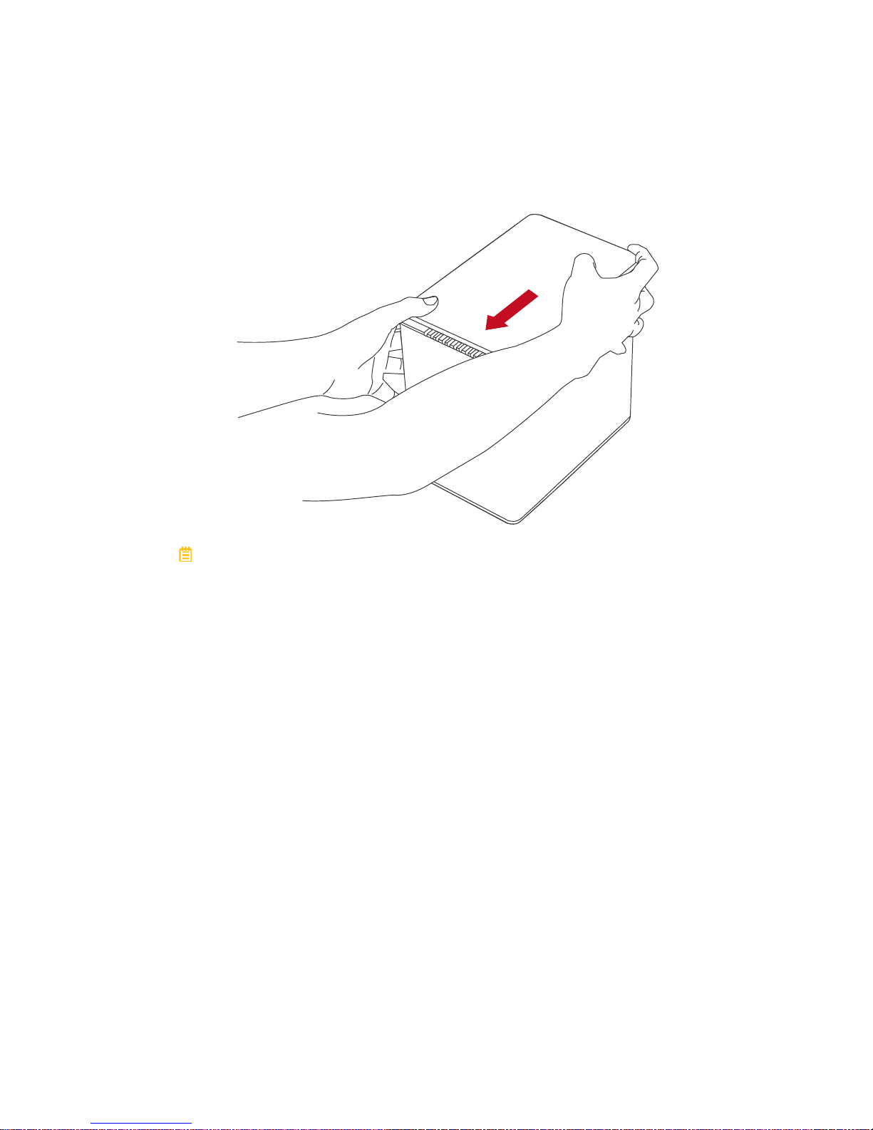
11. Place the RAID System with its Front View facing you and the top lid on.
Position both hands on the top lid, one in the front and one in the back.
Simultaneously, push the lid firmly downward and toward you, back to front.
A “click” sound would indicate grasp of the top lid security clasp.
Page 17
17
CONNECTING THE RAID SYSTEM TO A HOST
COMPUTER
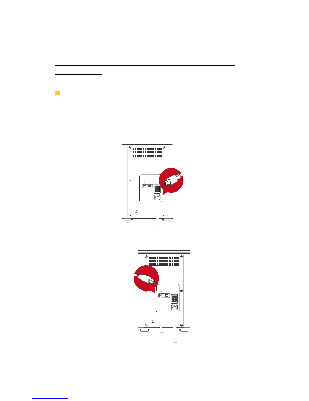
To connect the RAID System, please complete the following steps:
The ThunderboltTM technology is designed to control power supply/energysaving and time management between the host computer and connected
Thunderbolt
TM
-compatible devices. Therefore, both the External Power Supply
and the Thunderbolt
TM
Cable need to be connected with the RAID System before
the RAID System can be powered “ON”.
1. First, connect the AC/DC Power Adapter (External Power Supply).
DC IN
2. Then, insert both ends of the Thunderbolt
TM
Cable(s) into the corresponding
port of the RAID System and the host computer.
DC IN
Page 18
18
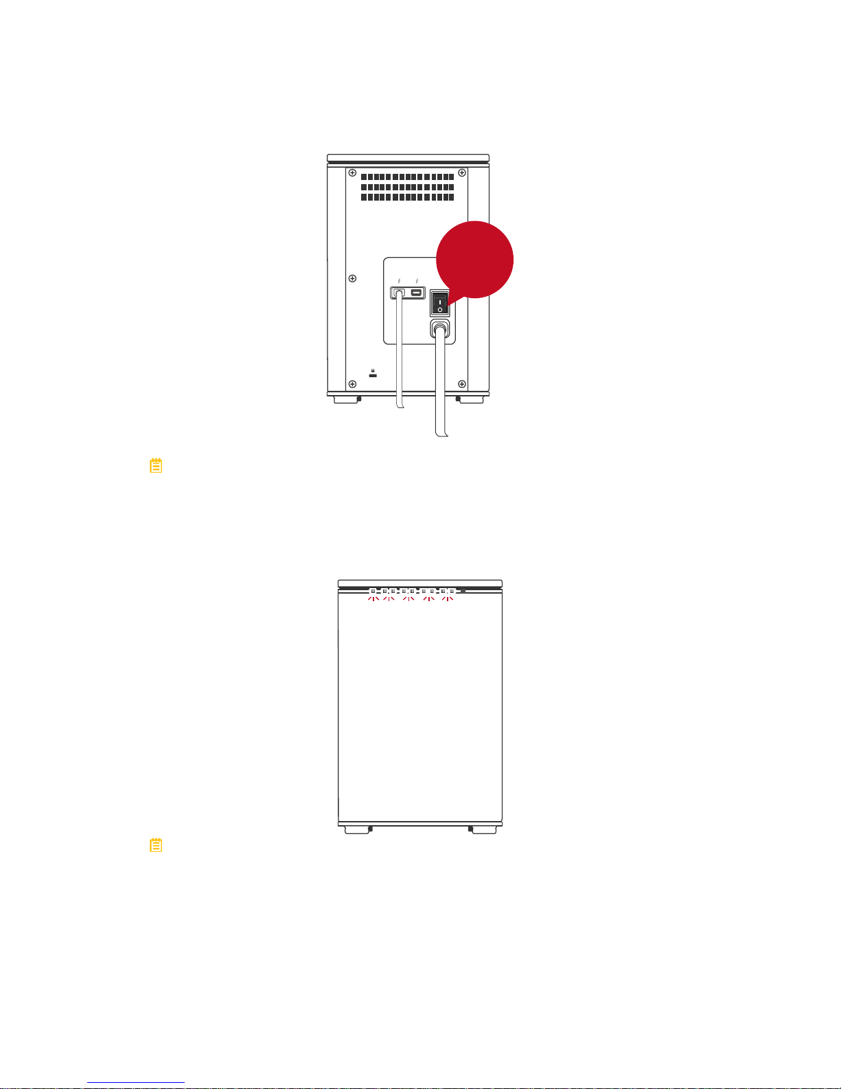
3. Finally, press the Power Switch to the “ON” position.
DC IN
ON
In order for networked computers to operate properly with the RAID System,
both the host computer and the RAID System must remain “ON” at all times.
4. When connected, the Power LED light will become steadily green. If the hard
drive/SSDs are inside the RAID System, the Disk LED lights will remain
steadily white. If there are no hard drive/SSDs inside the RAID System, the
Disk LED lights will not turn on.
By using the ThunderboltTM Cable, up to six ThunderboltTM Technologycompatible devices can be connected to the host computer, including: the
DataTale Thunderbolt
TM
Series, high-resolution displays, digital devices, and
much more. Please see Daisy Chain: Connecting Multiple Devices Section for
more information.
Page 19
19
NUMBER OF HARD DRIVE/SSD SUPPORTING
EACH RAID MODE
RAID Modes
Number of Hard Drive/SSD(s)
in the RAID System
JBOD (None RAID) 1 to 4
RAID 0 (Striping) 2 to 4
RAID 1 (Mirroring) 2
HYPERDUO
(Capacity/Safe)
1 Hard Drive and 1 to 3 SSDs
RAID 1+0 4
DISK SLOT NUMBER
Page 20
20
LED INDICATORS
For more information, please refer to “LED INDICATORS” under Glossary
section.
Power
Disk 4
Disk 3
Disk 2
Disk 1
RAID Alert
Green: On / Off
Red: On / Blink / Flash
White: On / Flash
Page 21
21
All Disks: Inserted / Detected
All Disks: NOT Inserted / Detected
All Disks: Disk 4 Data Access ONLY
All Disks: Disk 4 Error ONLY
All Disks: Disk 4 Rebuild ONLY
Fan: Error
Page 22

22
DAISY CHAIN: CONNECTING MULTIPLE DEVICES
By using the ThunderboltTM Cable, up to six ThunderboltTM Technologycompatible devices can be connected to the host computer via Daisy Chain,
including: the DataTale Thunderbolt
TM
Series, other computer hardware (i.e. DVD
writer), high-resolution displays, digital devices (i.e. digital video camera), and
much more. However, the process/transfer speeds of each device connected
along the Thunderbolt
TM
may vary depending on the device’s model/brand and its
original connection port itself. To maximize the process/transfer rates, it is highly
recommended to place the RAID System at the beginning of the chain,
connected directly to the host computer. For more information, please go to
Intel’s website at www.intel.com.
SAFE REMOVAL OF THE RAID SYSTEM
Safe removal of the RAID System from the host controller is highly
recommended. In order to safely remove the RAID System from the host
computer, one would need to eject the device on the actual host computer
system.
Page 23
23
SSD SMARTGUIDER KIT
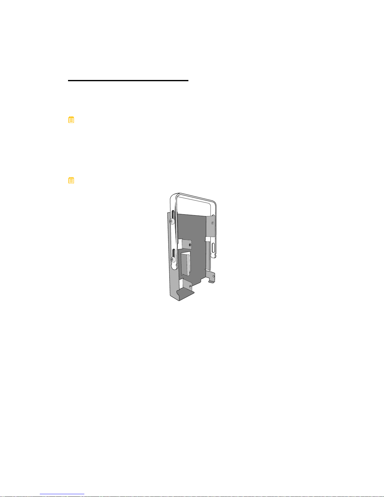
The SSD SmartGuider Kit can be utilized in any of the DataTale SMART Series
and is available for purchase separately. The SSD SmartGuider Kit is
compatible with most 2.5-inch hard drives or 9.5mm thick SSDs.
If 7.0mm thick SSD is used, please first stick the two (2) Damper Strips
(included in the Retail Package) onto the SSD Bracket before installing the SSD.
SSD SMARTGUIDER KIT: Package
Each RAID System includes one (1) set of SSD SmartGuider Kit within its
original package.
One (1) Spare SSD Screw is included in the package if needed.
SSD SMARTGUIDER KIT: SSD Compatibility
Due to restrictions of each individual SSD's controller and user's host system, not
all the SSDs are compatible when utilized with the RAID System. However,
based upon our testing results, here is a list of different SSD models/brands that
have successfully completed our compatibility tests:
Intel 520 Series: 60G, 240G
PATRIOT: PYROSE 120G, 240G, MAC Series XT 120G
Liteon: 120G
MemoRight FMT Plus: 120G, 240G
Regardless, there is no guarantee that these models/brands are compatible and
functional with the RAID System under any conditions or at all times.
Page 24

24
SSD SMARTGUIDER KIT: Installation
To assemble the SSD SmartGuider Kit onto a SSD, please complete the
following steps listed below:
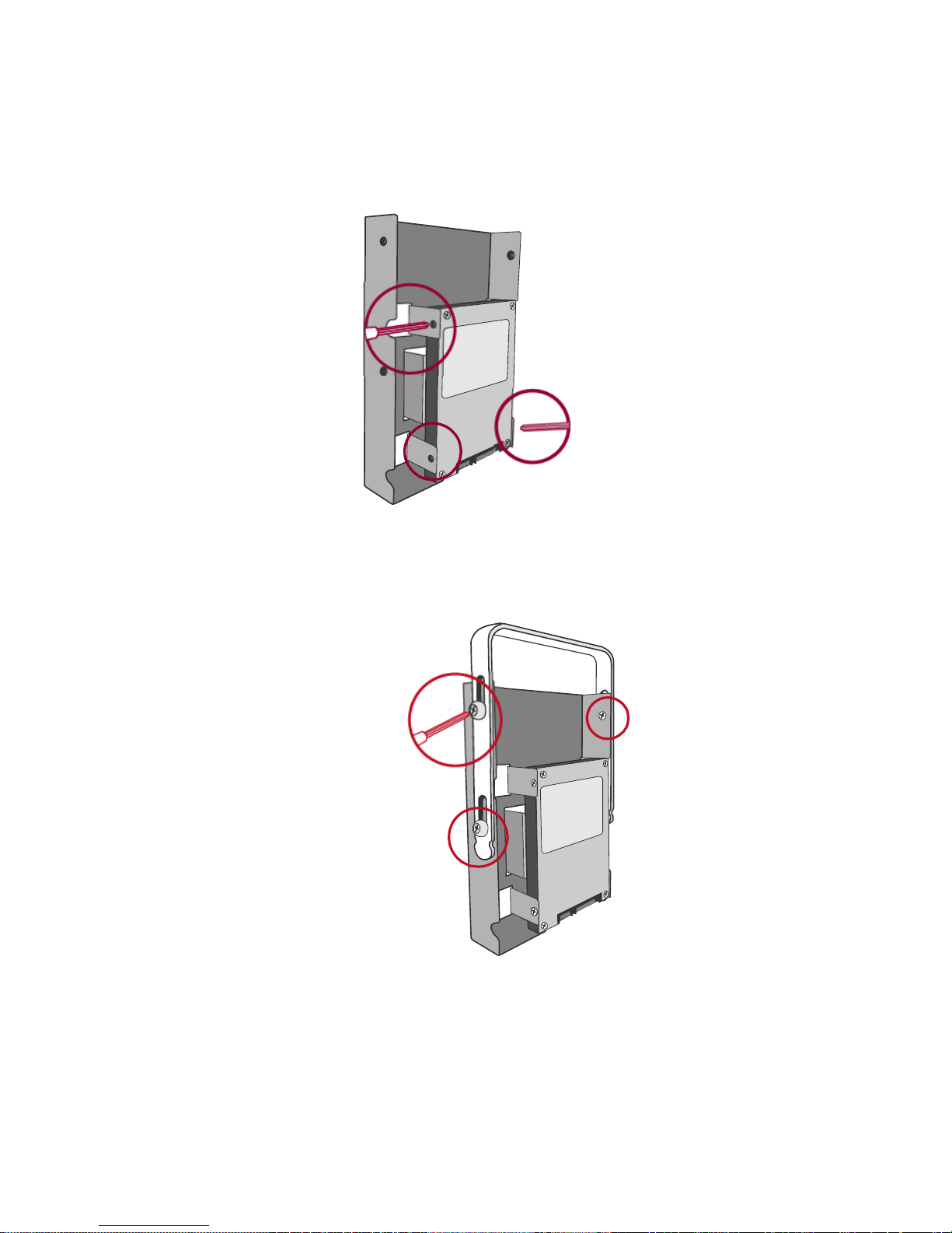
1. First, remove the Handle from the SSD Bracket by untightening the three (3)
larger Handle Screws, included in the package.
2. Second, place the SSD (the interface connectors oriented toward the opening
away from the Handle) into the SSD Insert on the SSD Bracket and align it
with the SSD Screw’s hole openings.
Connector
Page 25
25
3. Then, tighten the three (3) smaller SSD Screws onto the SSD and SSD
Bracket, included in the package.
4. After the SSD has been screwed properly onto the SSD Bracket, place the
Handle (away from the SSD interface connectors) onto the SSD Bracket and
aligned it with SSD Screw’s hole openings. Then, tighten the 3 larger Handle
Screws, included in the package.
Page 26
26
RAID MASTER
The RAID MASTER is a specially-designed GUI software specifically for our
DataTale SMART Thunderbolt
TM
RAID Systems. The RAID MASTER for Mac
will be provided via CD or our website. The RAID MASTER delivers a more
convenient yet modern way to manage the RAID System.
RAID MASTER: INSTALLATION
To install the RAID MASTER via CD, please insert the enclosed CD provided in
the package. To install the RAID MASTER via Internet, please download the
appropriate installation package file from our website at www.data-tale.com or
www.datawatchtech.com
before beginning the installation process.
INSTALLATION FOR MAC
Please follow the steps listed in the instructions provided below:
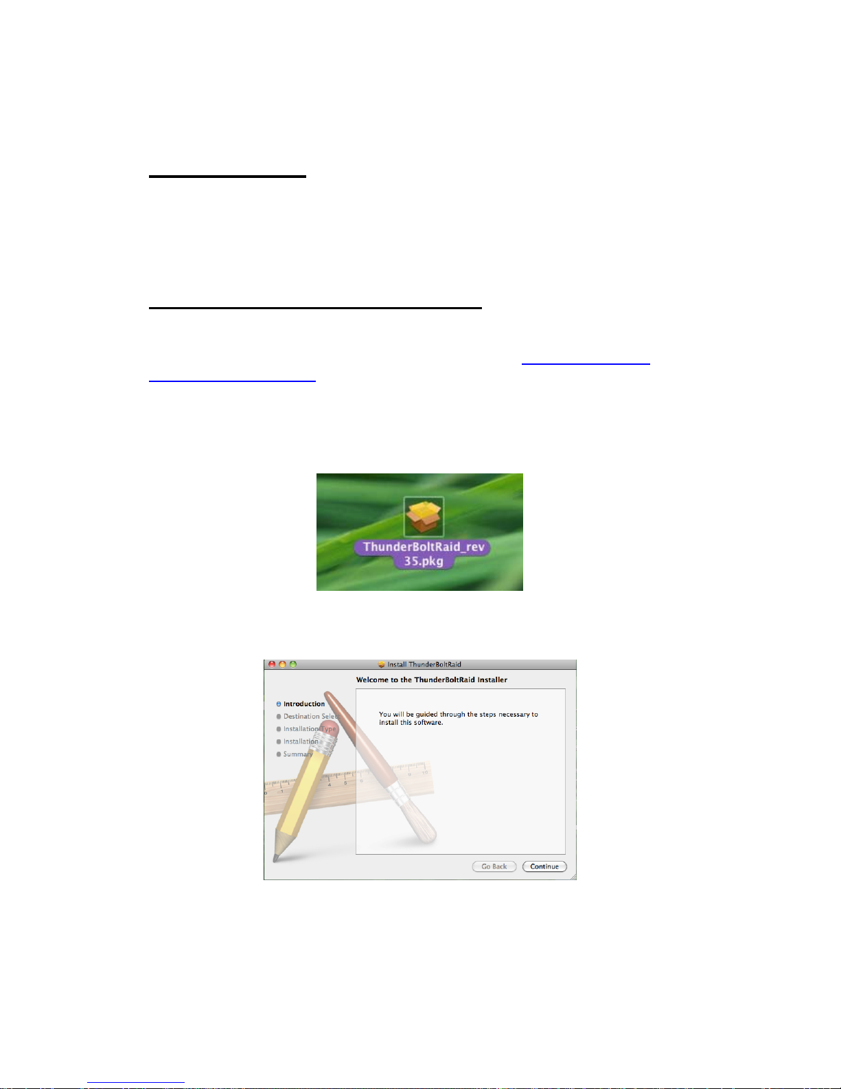
1. First, copy the “Pkg” file onto the host computer desktop, and double click
on the icon.
2. Ne xt, the MAC Software Inst aller will automatically appear with these
steps: Introduction, Destination Select, Installation Type, Installation, and
Summary. You will be guided through the steps necessary to install this
software. Please click “Continue” to begin the installation process.
Page 27
27
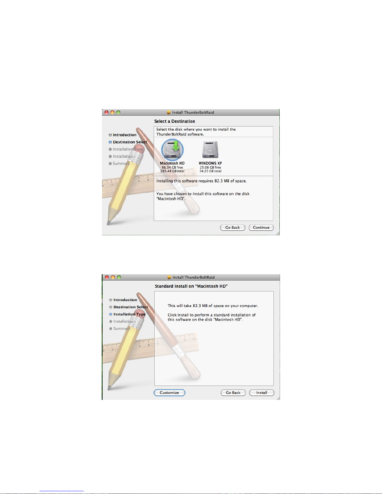
3. Then, under t he second step, you will need to select a disk to install the
RAID MASTER, which the host computer’s available disk(s) will appear for
selection. Once a disk is selected, the Installer will specify how much
space will be required to install this software. Please click “Continue” to
continue the installation process.
4. To personally change the Installation Type, please click “Customize” to
specify your preferences. If the Standard Installation is suitable for you,
simply click “Install” to continue the installation process.
Page 28
28
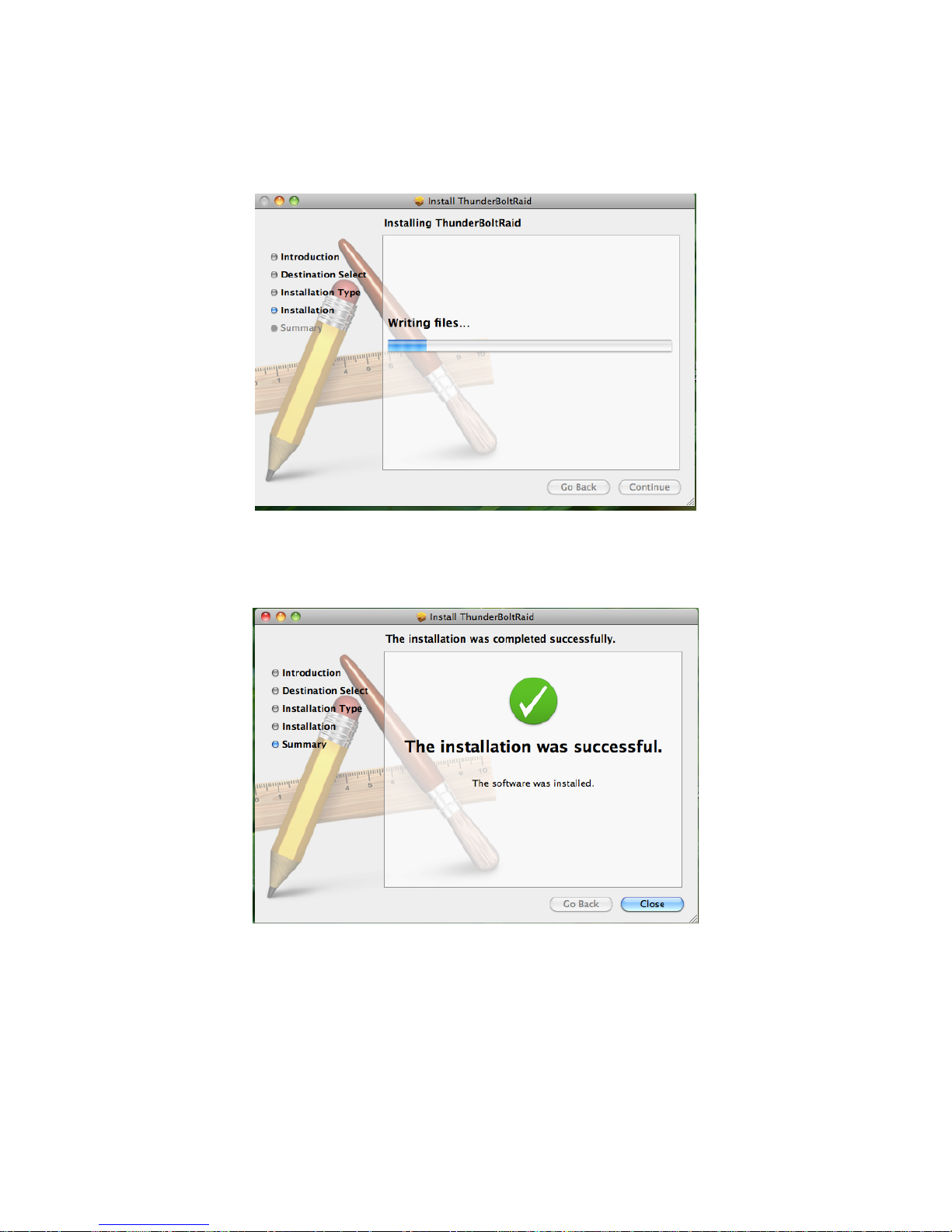
5. This step may take a few moments.
6. Once the RAID MASTER has been successfully installed, please click
“Close” to end the Installation process. Now, you may begin using the
RAID MASTER!
Page 29

29
The RAID MASTER icon will appear on the desktop and/or in the Applications
folder.
Due to MAC’s OS, installation and un-installation of RAID MASTER is
unnecessary. Simply repeat the steps mentioned above for any future
firmware updates or for un-installation.
Page 30

30
RAID MASTER: GUI
To operate RAID MASTER for the RAID System, please connect the RAID
System to the host computer (more information provided under Connecting the
RAID System to a Host Computer) and double-click on the RAID MASTER icon
to begin:
¾
INFORMATION: Provides basic information for the RAID
System, inserted Disks, and any available RAID Sets.
¾
CONFIGURATIONS: Provides RAID Mode configurations,
inserted Disks’ status, and a list of any available RAID Sets.
¾ SETTINGS: Provides current settings to adjust for Language.
¾
NOTIFICATIONS: Provides Email settings for notifications and
a Notification Center with an Event List to select which Events to notify.
¾
LOGS: Provides record of all the activities completed for the RAID
System and can save the log information as a text format file.
¾
FIRMWARE: Provides RAID System’s current Firmware
information and Firmware Update feature.
Page 31
31
RAID MASTER: FEATURES
INFORMATION
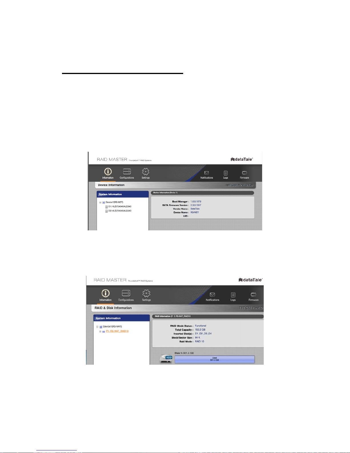
Once the RAID System is connected to the host computer, the RAID MASTER
will provide basic information of the RAID System under the Information icon.
¾
Device Information: Device number, Boot Manager (Chip itself), SATA
Firmware Version (Chip itself), Vendor Name (Brand), Device Name
(RAID System), and UID (Thunderbolt
TM
Unique Identification Number).
¾ RAID & Disk Information: Device number, RAID Set number (P#),
RAID Mode Status, Total Capacity, Inserted Disk(s), Block/Sector Size,
RAID Mode; and all inserted Disks’ type (HDD/SSD), volume (GB), and
Disk number.
Page 32

32
¾
Disk Information: Disk number (D#), Type (HDD/SSD), Model,
Disk/Used/Free Capacities, Status, Speed, Serial number, Firmware
Version (of the Disk itself), and Hard/Solid-State Disk(s) detailed
information
Once the RAID System is connected to the host computer, the RAID MASTER
will show detailed information of the RAID System and its inserted Disks.
Because the RAID MASTER can manage more than “one Unit” of the RAID
System, each RAID System connected to the host computer will reflect as
“Device” and in the numbering order of “Device1, Device2, …” respectively. The
System List will reflect the RAID Sets as “P1, P2, …” and the Disks as “D1,
D2, …” respectively.
Page 33
33
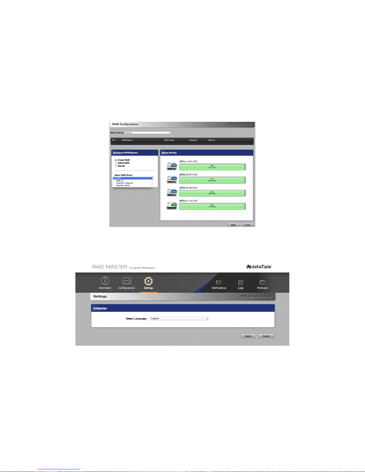
RAID CONFIGURATIONS: Provides a selection of which Devices to
choose from; a list of existing RAID Sets’ information (Number, RAID Name,
RAID Mode, Capacity, Disk Number); a selection of available RAID Modes to
choose from; and the inserted Disks’ status. There are operative selections to
choose from: Create RAID, Delete RAID, Rebuild, Select RAID Mode (Available
RAID Modes will appear based on number/type of Disks selected), and which
Disk(s) to select along with its individual capacity information.
SETTINGS: Provides current Language setting with a selection of available
Languages to choose from.
Page 34

34
NOTIFICATIONS: Provides email settings for notifications and a
Notification Center with an Event List to select which Events to notify, including:
SMTP Server Name, SMTP Server Port, Sender’s Email, Sender’s User Name,
Sender’s Password, Recipient’s Email, Send Mail Test, and Upload/Save Profile.
The Notification Center provides common Events to choose from, including:
RAID mode is broken, Rebuild process has failed, Data read/write process has
failed, RAID mode is degraded, Disk is unplugged, RAID is deleted, and Disk is
inserted.
EVENT LOG: Provides a record of all the activities completed for the RAID
System and option to save its information as a text format file, including: Event
No. in the order of occurrence, of which Device & under which RAID Mode, Date
& Time happened, Type of activity, Message available if any, to save the record
as a text format file under Save as File, to clear the record under Clear All, Total
number of Pages, and Go to which Page.
Page 35
35
FIRMWARE INFORMATION
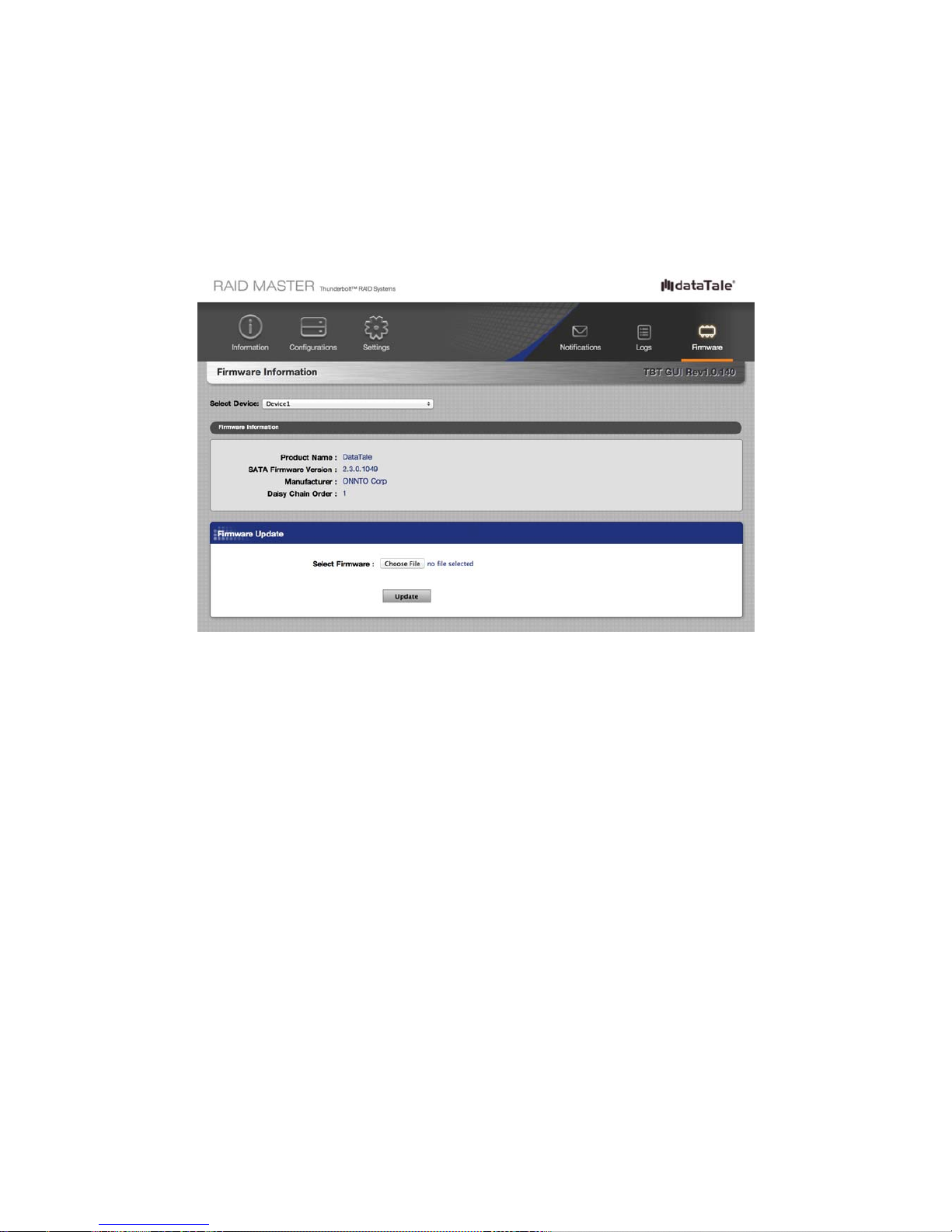
Provides RAID System’s current Firmware Information and Firmware Update
features, including: Product Name, SATA Firmware Version (Chip itself),
Manufacturer, and Daisy Chain Order (current selected Device), Select Firmware
to Update under Firmware Update.
Page 36
36
RAID MASTER: OPERATION
RAID CONFIGURATIONS: SET UP A NEW RAID SET
To set up a new RAID Set for the RAID System, please complete using the
following steps:
In order to change an existing RAID Set for the inserted Disks in the RAID
System, the existing RAID Set must be deleted first. Please complete the steps
under “RAID MODE: DELETE AN EXISTING RAID SET” first, and then continue
under “RAID MODE: SET UP”.
Please review under “Number of Hard Drive/SSD Supporting Each RAID
Mode” or individual “RAID Mode” sections under Glossary for more detailed
information and assistance on choosing the most suitable RAID Mode for your
needs. If the number/type of inserted Disks do not qualify for a particular RAID
Mode, that RAID Mode will not appear under Select RAID Mode list. More than
one RAID Set can be created for different Disk(s), but must be created
separately (For example, two sets of RAID 1 or combination sets of RAID 0/
RAID 1 for four Disks).
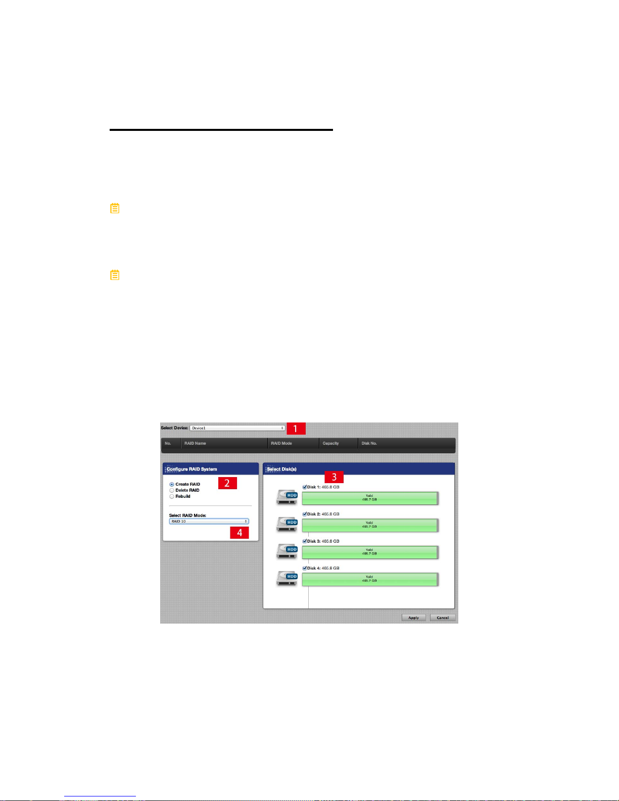
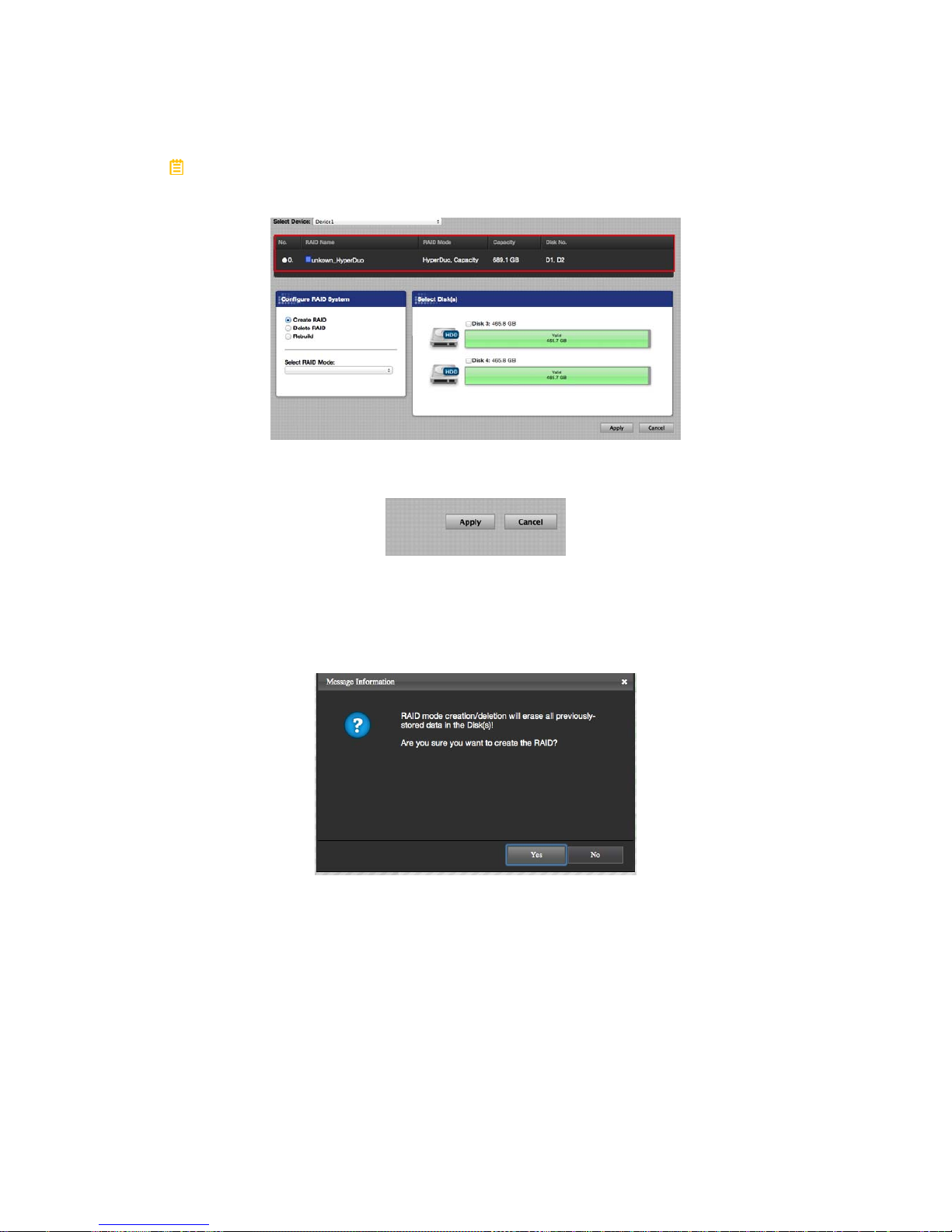
1. Click on th e Configur at ions icon and select the available options based on
preferences by following the steps in the picture.
Page 37
37
A list of existing RAID Set(s) may appear if the inserted Disk(s) are already
pre-formatted by the RAID MASTER.
2. Then, click on the Apply icon to begin.
3. Once begin, the RAID MASTER will display a Popup Window stating,
“RAID Mode creation/deletion will erase all previously-stored data in the
Disk(s)! Are you sure you want to create the RAID?” Click on the Yes icon
to confirm and continue the process.
Page 38
38
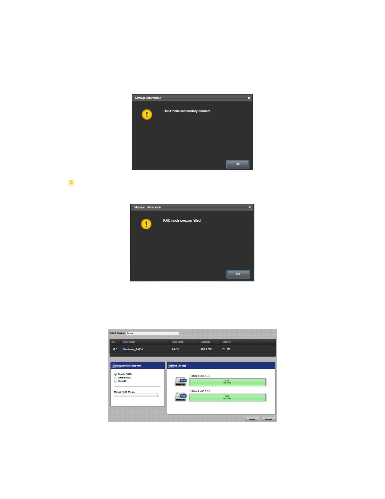
4. Once the RAID Creation process is completed, the RAID MASTER will
display a Popup Window stating, “RAID mode successfully created!” Click
on the “OK” icon to confirm and finish the process.
If the new RAID Set creation has failed, the RAID MASTER will display a
Popup Window stating, “RAID mode creation failed!” Click on the “OK” icon to
confirm and double check on the Inserted Disk(s) before restarting the process.
5. Now, the newly created RAID Set will appear under the RAID Set list
reflecting basic information. The chosen Disks for the new RAID Set will
disappear and only the available (Valid) Disk(s) under Select Disk(s) will
appear. The newly created RAID Set is now ready for usage in the RAID
System!
Page 39
39
RAID CONFIGURATIONS: DELETE AN EXISTING RAID
SET
To delete an existing RAID Set for the inserted Disk(s) in the RAID System,
please complete using the following steps:
Deleting an existing RAID Set will erase all data stored on the Disk(s). If there
are saved data in the Disk(s), please remember to backup all the data before
deleting the existing RAID Set.
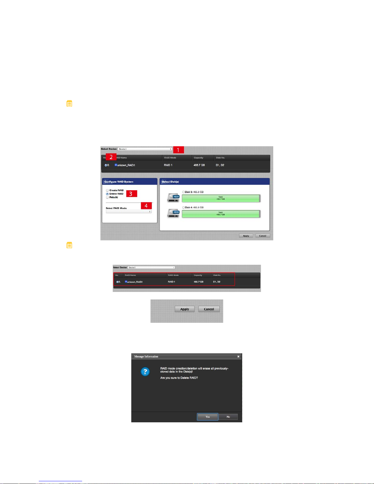
1. Click on the Configurations icon and select the options based on
preferences by following the steps in the picture.
A list of existing RAID Set(s) should appear for the inserted Disk(s). If the
preferred RAID Set does not appear on the list, please restart/connect the RAID
System and the host computer.
2. Then, click on the Apply icon to begin.
3. Once begin, the RAID MASTER will display a Popup Window stating,
“RAID Mode creation/deletion will erase all previously-stored data in the
Disk(s)! Are you sure you want to Delete RAID?” Click on the Yes icon to
confirm and continue the process.
Page 40
40
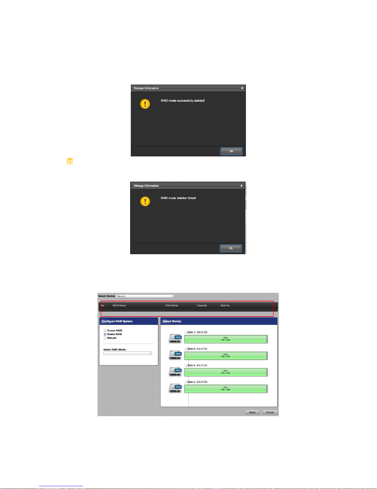
4. Once the RAID deletion process is completed, the RAID MASTER will
display a Popup Window stating, “RAID mode successfully deleted!” Click
on the “OK” icon to confirm and finish the process.
If the new RAID Set deletion has failed, the RAID MASTER will display a
Popup Window stating, “RAID mode deletion failed!” Click on the “OK” icon to
confirm and restart the process.
5. Now, the deleted RAID Set will disappear from under the RAID Set list.
The previously-chosen Disks for the deleted RAID Set will reappear as
available (Valid) Disk(s) under Select Disk(s). The available (Valid) Disk(s)
are now ready for usage!
Page 41
41
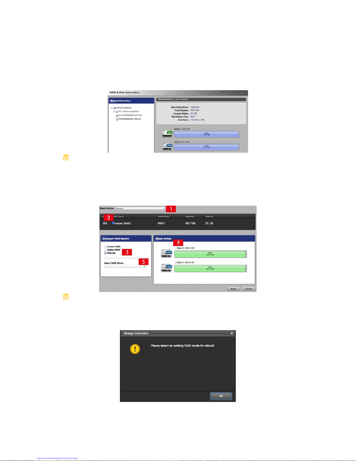
RAID CONFIGURATIONS: REBUILD A RAID SET
To Rebuild a degraded or broken RAID Set, please complete using the following
steps:
If the RAID System loses connection to the host computer, the Rebuild
process will stop. Even if the RAID System is powered off, the RAID System will
retain the Rebuild status in memory. When the RAID System is powered “on”
again, the Rebuild process will resume from the previous status.
1. Click on the Configurations icon and select the options based on
preferences by following the steps in the picture.
If an existing RAID Set is NOT dotted for Rebuild under the list of existing
RAID Set(s) for the inserted Disk(s), the RAID MASTER will display a Popup
Window stating, “Please select an existing RAID mode for rebuild”. If the
preferred RAID Set does not appear on the list, please restart/connect the RAID
System and the host computer.
Page 42

42
2. Then, click on the Apply icon to begin.
3. Once begin, the RAID MASTER will display a Popup Window stating,
“RAID Mode creation/deletion will erase all previously-stored data in the
Disk(s)! Are you sure you want to rebuild the RAID mode?” Click on the
Yes icon to confirm and continue the process. The Rebuild process may
take a few moments, please do not disconnection or Power Off the RAID
System/host computer at this time unless necessary.
4. Once the RAID Rebuild process is completed, the RAID MASTER will
display a Popup Window stating, “RAID mode successfully rebuild!”
Click on the “OK” icon to confirm and finish the process.
If the RAID Rebuild has failed, the RAID MASTER will display a Popup
Window stating, “RAID mode rebuild failed! …!” Click on the “OK” icon to
confirm and double check on the Inserted Disk(s) before restarting the
process.
Page 43
43
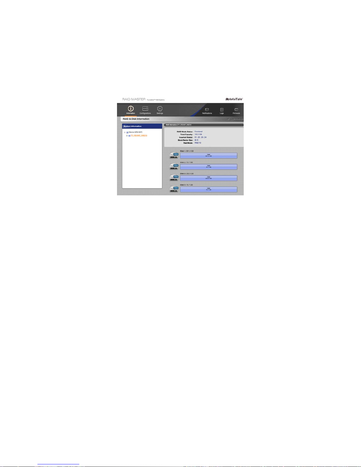
5. After the Rebuild process is completed, the data in the new hard
drive/SSD will replace the damaged or non-functioning hard drive/SSD.
The RAID Mode Status should state, “Functional” under RAID
Information. Remember to remove the non-functional Disk(s) before
continue using the RAID System!
Page 44
44
GLOSSORY
Detailed descriptions and/or pictures are provided as reference for better
understanding of the RAID System and RAID MASTER. For any technical
troubleshooting issues, please review the “Troubleshooting” and/or “Teach Me”
sections under Support.
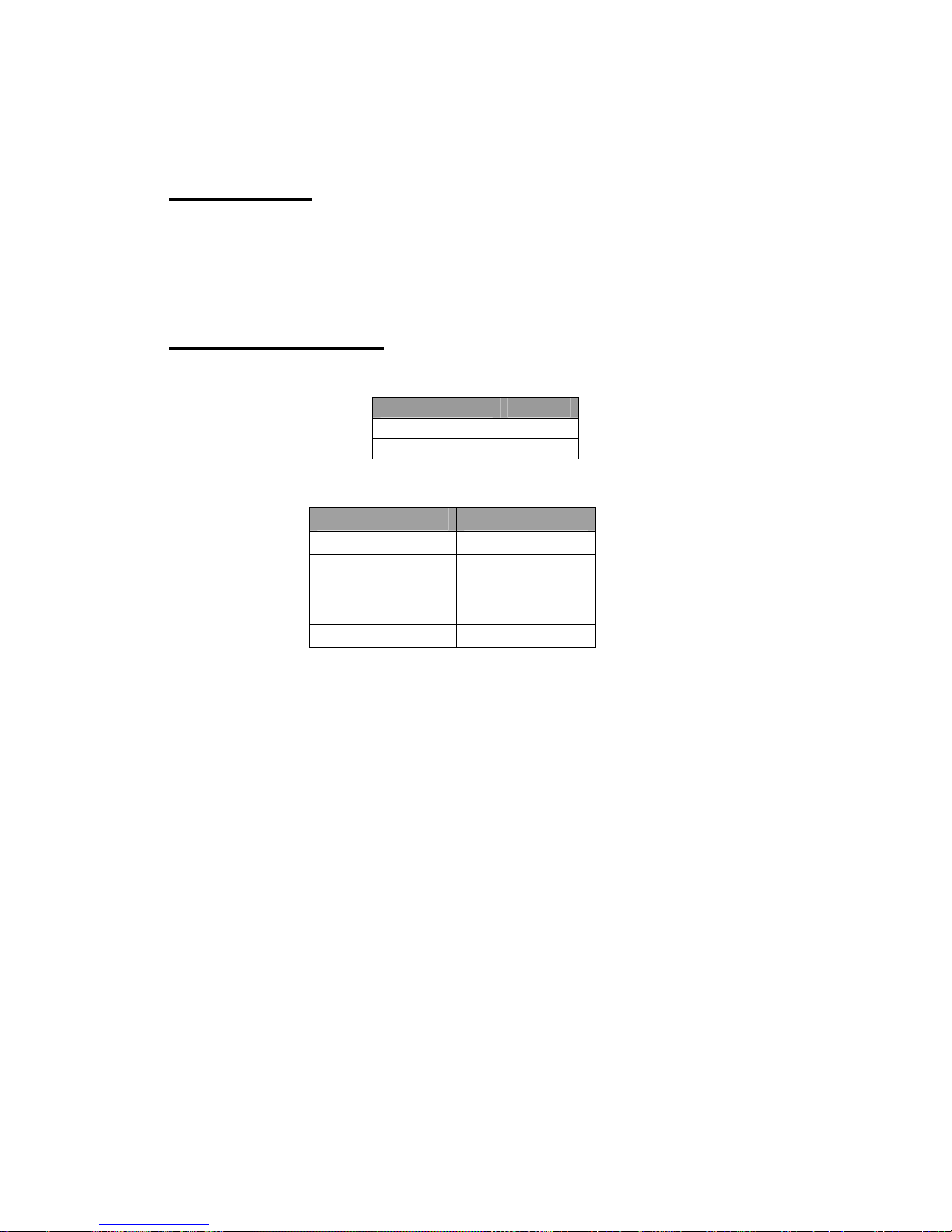
LED INDICATORS
Power LED x 1
Indicators Color
Power on
Green
Power off
None
RAID ALERT LED x 1
Indicators Color
Healthy None
Rebuild Blink Red
Broken or
Degrade
Red
Fan Error Flash Red
DISK LED x 8
There are 2 LEDs for each Disk Slot. The left Disk LED indicates
“Connection/Access” and the right Disk LED indicates “Health”.
The Connection/Access Disk LED is only one-color (white). When the RAID
System is connected and a hard drive/SSD is inserted, the white Disk LED will be
on. When the hard drive/SSD is being accessed or rebuilding, the white Disk
LED will flash. When the hard drive/SSD is not healthy, the white Disk LED will
also be on.
The Health Disk LED is only one-color (red). When the hard drive/SSD is not
healthy, the red Disk LED will be on. When hard drive/SSD is healthy and
rebuilding as a Target Disk, the red Disk LED will blink.
Page 45
45
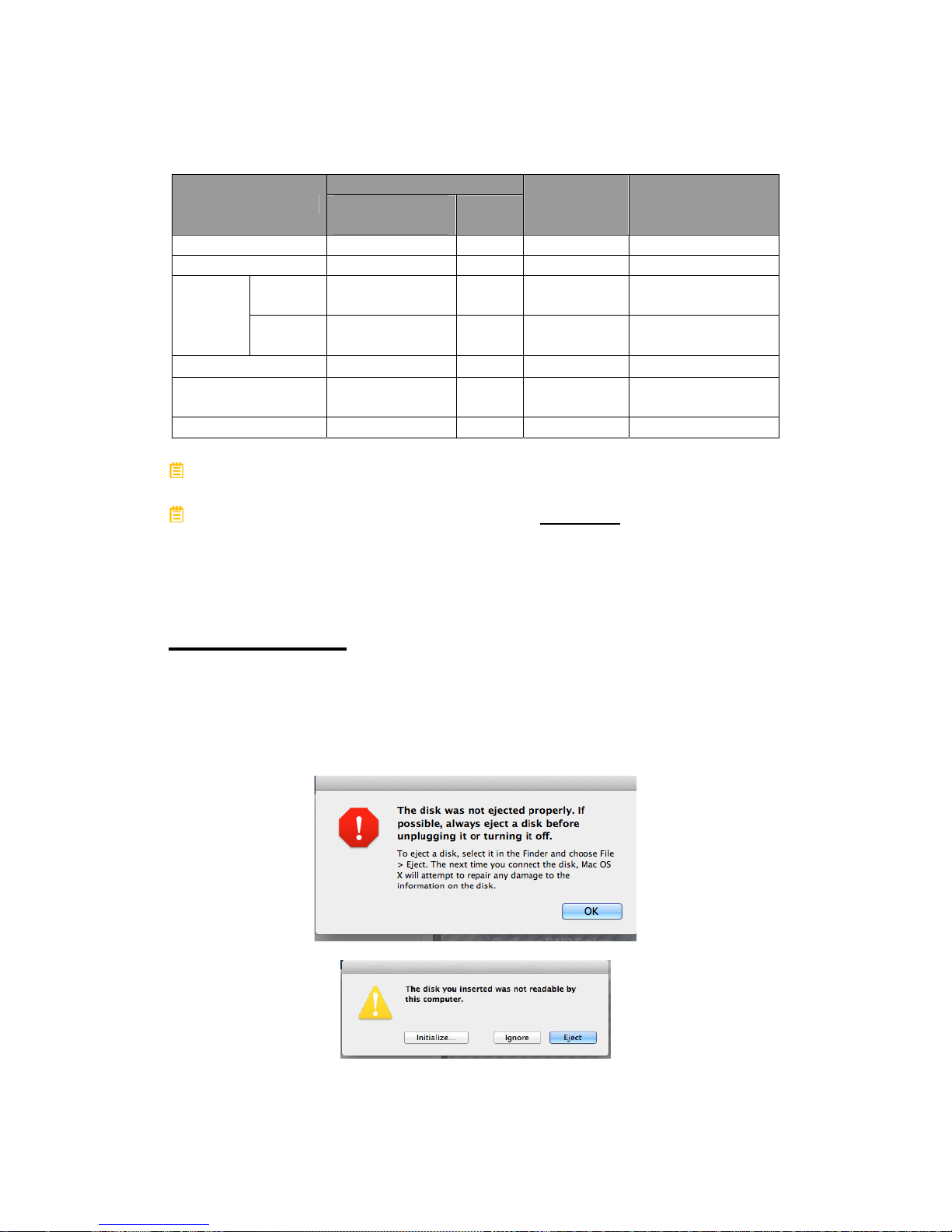
Disk (1, 2, 3, 4)
Indicator
Connection/
Access
Health
RAID Alert RAID Mode
Disk Error
White Red Red ALL
Data Access
White (Flash) None None ALL
Source
Disk
White (Flash) None Red (Blink)
RAID 1 and 1+0
Disk
Rebuild
Target
Disk
White (Flash)
Red
(Blink)
Red (Blink)
RAID 1 and 1+0
Fan Error
None None Red (Flash)
ALL
Disk Not
Detected
None None None
ALL
Disk Detected
White None None ALL
The difference between a flashing LED and a blinking LED is that flashing
shows slow yet long pulses, and blinking shows fast yet short pulses.
Due to the chipset design, the LED Indicators WILL NOT be able to display
any status alerts for Disk Error and Rebuild process when the RAID MASTER is
CLOSED. Hence, if prefer to receive all alerts and monitor all features via LED
Indicators, please keep the RAID MASTER "ON" at all times. Nevertheless, this
will not affect any of the RAID MASTER operations and functions.
RAID MASTER
POPUP WINDOWS
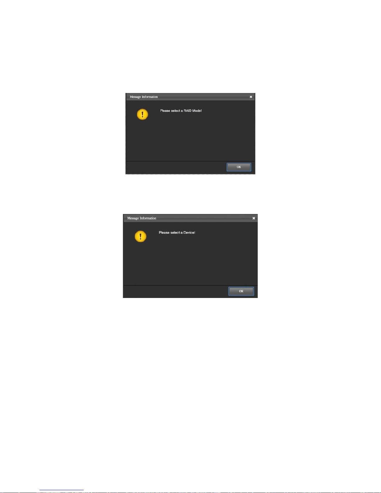
¾ EJECTED
Either Popup Windows may appear as a warning whenever a RAID Set is
created, deleted, or rebuild. It may also appear if any of the inserted
Disk(s) have become “non-functional”.
Page 46
46
¾ SELECT A RAID MODE
This Popup Window may appear as a warning whenever a RAID Mode
(Create) and/or an existing RAID Set (Delete) are not selected under
RAID Configurations.
¾ SELECT A DEVICE
This Popup Window may appear as a warning whenever a Device is not
selected under any of the Main pages of the RAID MASTER.
¾ BROKEN
A “Broken” Popup Window may appear as a warning if any of the inserted
Disk(s) in a RAID Set have become “non-functional”.
¾ DEGRADE
A “Degrade” Popup Window may appear as a warning if any of the
inserted Disk(s) in a RAID Set have become “non-functional” and the
RAID Set is in danger of losing its stored data unless proper steps are
taken.
Page 47

47
REBUILD
The RAID MASTER’s Rebuild feature is available manually under RAID 1 and
RAID 1+0. If one of the existing RAID Set becomes “degraded/broken”,
functional hard drive/SSDs can be inserted to Rebuild and recover the data
within the degraded/broken RAID Set. However, recovery of the data/RAID Set
depends on each situation (RAID Mode, number of “non-functional” Disks, etc).
The use of identical hard drive/SSDs from the same manufacturer, having the
same capacity and RPM is highly recommended
.
Please read the "REBUILD: …" section under “RAID MASTER: OPERATION”
for more information.
RAID MODES
A Redundant Array of Independent (or Inexpensive) Disks (RAID) is a system
that utilizes multiple hard drive/SSDs to share or replicate data among the hard
drive/SSDs. The benefit, depending on the selected RAID Mode (combinations
of disks), is one or more of increased data integrity, fault-tolerance, throughput or
capacity as a single drive when compared to individual hard drive/SSDs.
Any RAID mode changes or deletions will erase all the existing data inside the
hard drive/SSD. It is highly recommended
to save all existing data to another
hard drive/SSD before performing any RAID mode changes or deletions.
Using identical hard drive/SSDs with the same capacity and RPM, and from
the same manufacturer are highly recommended
for best performances.
Page 48
48
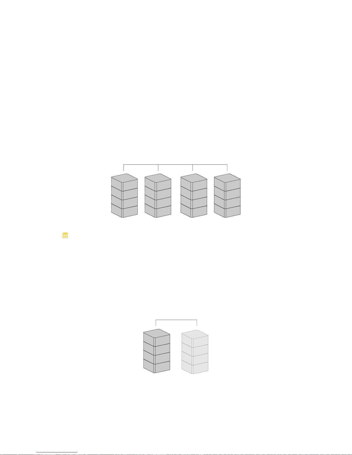
RAID 0 (Striping)
RAID 0 (Striping) is a performance-oriented, non-redundant data mapping
technique. It combines multiple hard drive/SSDs into a single logical System.
Instead of seeing several different hard drive/SSDs, the operating system sees
only one large drive. Striping splits data evenly across two or more hard
drive/SSDs simultaneously, dramatically increasing performance.
Striping can be implemented in hard drive/SSDs of differing sizes, but the
storage space added to the array by each hard drive/SSD is limited to the size of
the smallest hard drive/SSD. Although Striping is an easily implemented and
simple configuration, Striping should never be used for mission critical
applications. The speed of operation is fast in comparison to other RAID modes.
RAID 0
Disk 1 Disk 2 Disk 3 Disk 4
A1
B1
C1
D1
A2
B2
C2
D2
A3
B3
C3
D3
A4
B4
C4
D4
In Striping mode, if one hard drive/SSD in the RAID System fails, all data in
both installed hard drive/SSDs will be lost.
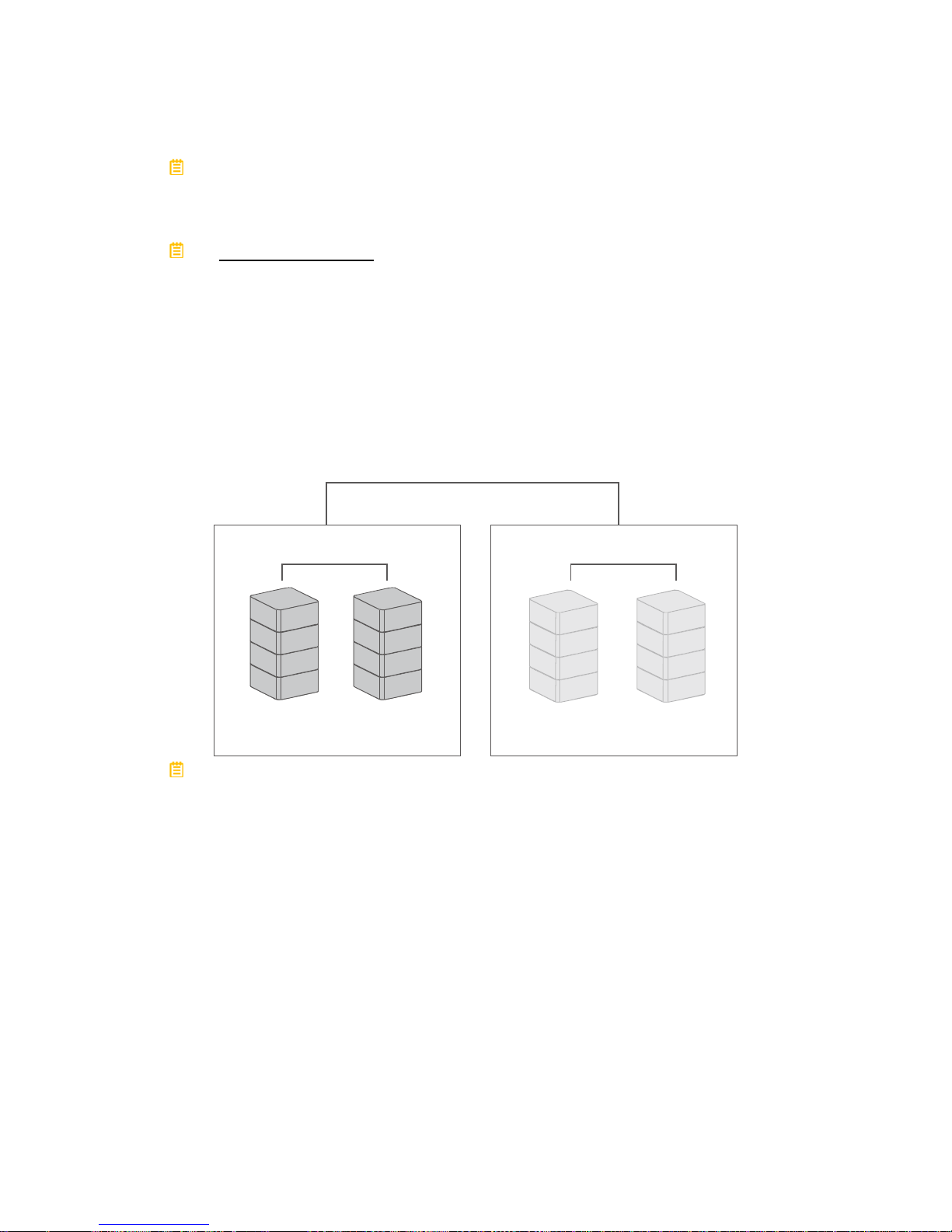
RAID 1 (Mirroring)
RAID 1 (Mirroring) consists of at least two (2) hard drive/SSDs storing duplicate
copies of the same data. In this mode, the data is simultaneously written to two
(2) hard drive/SSDs. Thus, the storage capacity of a two-disk array is combined
into a single disk and the capacity is limited to the size of the smallest hard
drive/SSD. The speed of operation is average in comparison to other RAID
modes.
RAID 1
Disk 1
Disk 2
A
B
C
D
A
B
C
D
Page 49
49
In Mirroring mode, if one of the hard drive/SSDs fails, either Source Disk or
Spare Disk, the data is still available. However, if the Source Disk fails during the
Rebuild process, the data in both hard drive/SSDs will be lost.
It is NOT recommended to do hot swap for the Source Disk during the
Rebuild process because it may cause the Rebuild process to fail and the data in
both hard drive/SSDs will be lost.
RAID 1+0
In RAID 1+0, the data is first mirrored and then striped. Under this RAID Mode, it
provides another way to achieve higher performance and data security, while
increasing complexity. The speed of operation is average in comparison to other
RAID modes.
Mirror
Striping
RAID 1+0
Disk 1
Disk 2
Mirror
Disk 3
Disk 4
RAID 1+0 requires a minimum of four (4) hard drive/SSDs in an array. If one
of the hard drive/SSDs becomes defective, the original and identical backed up
data is still available offhand.
JBOD (None RAID)
Just a Bunch of Disks (JBOD) refers to a group of hard drive/SSDs. In JBOD, the
number of logical hard drive/SSDs is equal to the number of physical hard
drive/SSDs. This mode allows the RAID System to operate as a multi-disk
storage enclosure, but provides no data redundancy. The speed of operation is
fast in comparison to other RAID modes.
Page 50
50
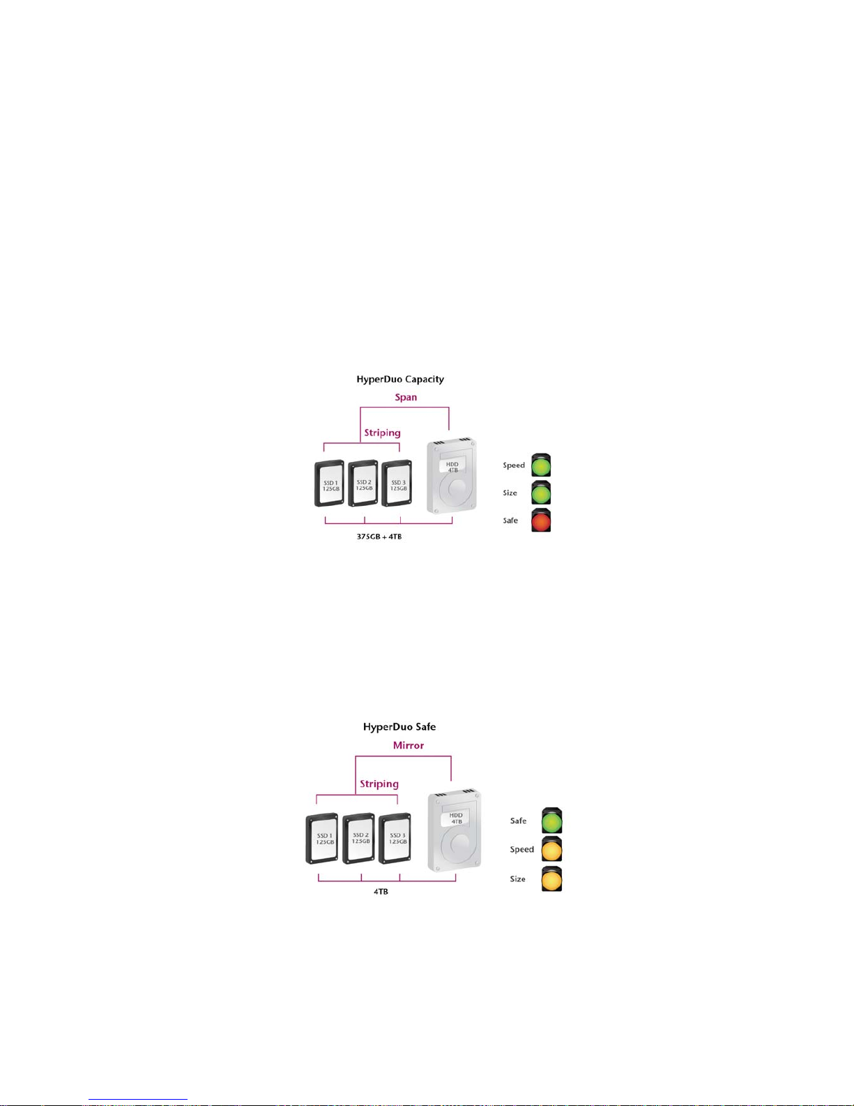
HyperDuo: Capacity and Safe
The HyperDuo feature allows only one (1) hard drive, and can support at least
one (1) up to three (3) additional solid-state drives. It has two RAID modes:
Capacity Mode and Safe Mode.
The Capacity Mode provides maximum capacity available by combining both the
SSD(s) and hard drive, while performing at SSD speeds, unless all the SSD(s)
are full. Under Capacity Mode, data is striped into all the SSD(s). Then, if the
SSD(s) are full, additional data is stored via Span into the hard drive and
performance speeds are decreased. The total volume available is based on all
the SSD(s) and hard drive combined. If either the hard drive or SSD(s) becomes
defective, all data will be lost.
The Safe Mode provides optimal data protection without affecting data read
speeds, but data write speeds are decreased for maximum resiliency. Under
Safe Mode, data is striped into all the SSD(s), and at the same time, the same
data is mirrored into the hard drive. Then, if the SSD(s) are full, additional data is
stored via Span into the hard drive. The total volume available is based on the
hard drive alone. If all the SSD(s) becomes defective but the hard drive is still
functional, the original and identical backed up data is still available offhand.
Page 51

51
APPENDIX: SPECIFICATIONS
Model Name RS-M4T
Connector
Thunderbolt
TM
ports x 2
Disk Support
3.5” & 2.5” SATA hard drive
2.5” SSD*
*Identical hard disk recommended – same
manufacturer, capacity and RPM
RAID Mode*
JBOD (None RAID), RAID 0 (Striping), RAID 1
(Mirroring), RAID 10 (1+0), HyperDuo
(Capacity/Safe), and Rebuild
Additional RAID modes and features will be provided via our
website
Data Transfer Speed
Up to 10Gbit/sec
System Material
Aluminum case with plastic parts
LED Indicators
Power / Connection / Health / Access / Rebuild /
RAID Alert/ Fan Error
Power Supply
Input: AC 100-240V
Output: DC +12V/7.5A
FAN
High Performance Fans x 2
Dimension
210 (L) x 138 (W) x 213 (H) mm
8.27 (L) x 5.45 (W) x 8.39 (H) inches
Weight (without Disk)
2.2 kgs, 5.33 pounds (lbs)
Certification
CE, FCC, Thunderbolt
TM
 Loading...