

Page 1
1
Rev.01
Page 2

2
TableofContents
GENERALINFORMATION ........................................................................................ 3
Copyright.............................................................................................................................................................. 3
NoticesandClassifications ........................................................................................................................... 3
ContactUs............................................................................................................................................................3
PRECAUTIONSFORTHEENCLOSURE............................................................... 4
INTRODUCTION ...................................................................................................... 5
Features................................................................................................................................................................ 5
SYSTEMREQUIREMENT .......................................................................................... 6
PC................................................................................................................................................................................. 6
MAC............................................................................................................................................................................. 6
OptionalAccessories .......................................................................................................................................6
PACKAGECONTENTS............................................................................................... 6
HUM10J ................................................................................................................................................................... 6
SYSTEMUNITVIEWS............................................................................................... 7
Rear/FrontView ............................................................................................................................................... 7
BottomView ....................................................................................................................................................... 7
InsideView.......................................................................................................................................................... 7
ASSEMBLINGTHEENCLOSURE ................................................................................ 8
PUTTINGON&SWITCHINGPOWERPLUGONAC/DCADAPTER............................ 10
CONNECTINGTHEENCLOSUREUNITTOACOMPUTER.......................................... 11
LEDSTATUS .......................................................................................................... 12
SAFEREMOVALOFTHEENCLOSURE ..................................................................... 12
EXTERNALBOOTUP............................................................................................... 12
PC...............................................................................................................................................................................12
MAC...........................................................................................................................................................................12
Q&As .................................................................................................................... 13
HardDriveCapacity...................................................................................................................................... 13
DiscrepancyinReported&ActualSizeCapacity.............................................................................. 13
APPENDIX:SPECIFICATIONS.................................................................................. 15
Page 3

3
GENERAL INFORMATION
Copyright
Copyright @ 2011 Data Watch Technologies Co., Ltd. All rights reserved. No
part of this publication may be reproduced, stored in a retrieval system, or
transmitted in any form or by any means, electronic, mechanical,
photocopying, recording or otherwise, without the prior written consent of Data
Watch Technologies Co., Ltd or ONNTO Corporation.
The product information provided in this manual is subject to change
without prior notice and does not represent a commitment on behalf of the
vendor. The vendor assumes no liability or responsibility for any errors that
may appear in this manual.
Notices and Classifications
FCC-B Radio Frequency Interference Statement
This device complies with Part 15 of the FCC rules. Operation is subject to
the following two conditions:
This device may not cause harmful interference.
This device must accept any interference received, including interference that
may cause undesired operation.
This equipment has been tested and found to comply with the limits for
a Class B digital device, pursuant to Part 15 of the FCC rules. These limits
are designed to provide reasonable protection against harmful interference
when the equipment is operated in a commercial environment. This
equipment generates uses and can radiate radio frequency energy and, if not
installed and used in accordance with the instruction manual, may cause
harmful interference to radio communications.
Contact Us
We are committed to offer economical, high-quality connectivity and storage
enclosure solutions to the market. Your questions, inquiries or comments are
welcomed. For the latest version of User Manual & Technical Support, please
go to our website at www.data-tale.com
Data Watch Technologies Co., Ltd.
3F, No. 60, Lane 321, Yang Guang St.,
Nei Hu, Taipei 114 Taiwan
Tel: +886-2-8797-8868
Fax: +886-2-8797-4801
Email: [email protected]
Page 4

4
PRECAUTIONS FOR THE ENCLOSURE
♦ The main circuit board of the Enclosure is susceptible to static
electricity. Proper grounding is required to prevent electrical damage
to the Enclosure or other connected devices, including the host
computer. Always place the Enclosure on a smooth surface and avoid
all dramatic movement, vibration and percussion.
♦ Do NOT allow water to enter the Enclosure.
♦ Installation of additional equipment in the host computer may be
required. Visit our website to download the latest product information
updates.
♦ Do NOT attempt to service this device yourself. Disassembling the
Enclosure’s inner parts will expose you to dangerous voltages or other
hazards.
♦ Do NOT block the ventilation. Proper airflow is required to ensure
reliable operation and to prevent overheating.
♦ Do unplug the Enclosure from the electrical outlet when not in use to
provide an ecological friendly environment.
♦ Use only the power supply cable provided with the Enclosure.
Page 5

5
INTRODUCTION
Thank you for purchasing the Crystal USB 3.0 3.5-inch HDD Enclosure. The
Crystal USB 3.0 3.5-inch HDD Enclosure provides stylish yet ozone-friendly
housing environment for any 3.5” SATA hard drive, with the new SuperSpeed
USB 3.0 technology.
The installation instructions in this manual apply to the following models:
HU-M10J (USB 2.0/3.0 combination)
Please thoroughly read and follow the instructions provided in this
manual. Failure to do so may result in damage to the Enclosure, and any or
all of the connected devices.
Features
Supports SATA compliant hard drive
Features hot-plug and hot-swap
Increases heat dissipation and saves desktop space by utilizing an
upright position so hot air can naturally float through the top panel
ventilation holes
Reveals instant status via hidden LED shining downward onto surface
Provides steady and firm stance via curved rubber feet on the housing
bottom panel
Available data transfer speed up to 480Mbits/s (under USB 2.0) and up
to 5Gbits/s (under USB 3.0)
Reduces power consumption with hard drive spin up/down support
Connects to host by plug-n-play, not requiring any IT expertise or
software installation
Powers on/off via USB cable instead of A/C adapter or power button
Compatible with both Hi-Speed USB and SuperSpeed USB (USB 2.0
and 3.0)
Page 6
6
SYSTEM REQUIREMENT
To use the Crystal USB 3.0 3.5-inch HDD Enclosure, the minimum system
configuration in the host computer require the following:
PC
500MHz or faster CPU
256MB or higher RAM
Microsoft Windows XP, 2003, Vista, 2008, 7 or higher
One available USB 2.0 or USB 3.0 port
MAC
Macintosh PowerPC or Intel processor
256MB or higher RAM
Mac OS X 10.3 or higher
One available USB 2.0 or USB 3.0 port
Optional Accessories
USB 3.0 host card
Because many host computers do not feature USB 3.0 ports yet, an USB
3.0 PCI Express Card (for desktop computer) or an USB 3.0 ExpressCard 34
(for laptops) may be purchased to permit the maximum data speed possible
when utilizing the Crystal USB 3.0 3.5-inch HDD Enclosure.
PACKAGE CONTENTS
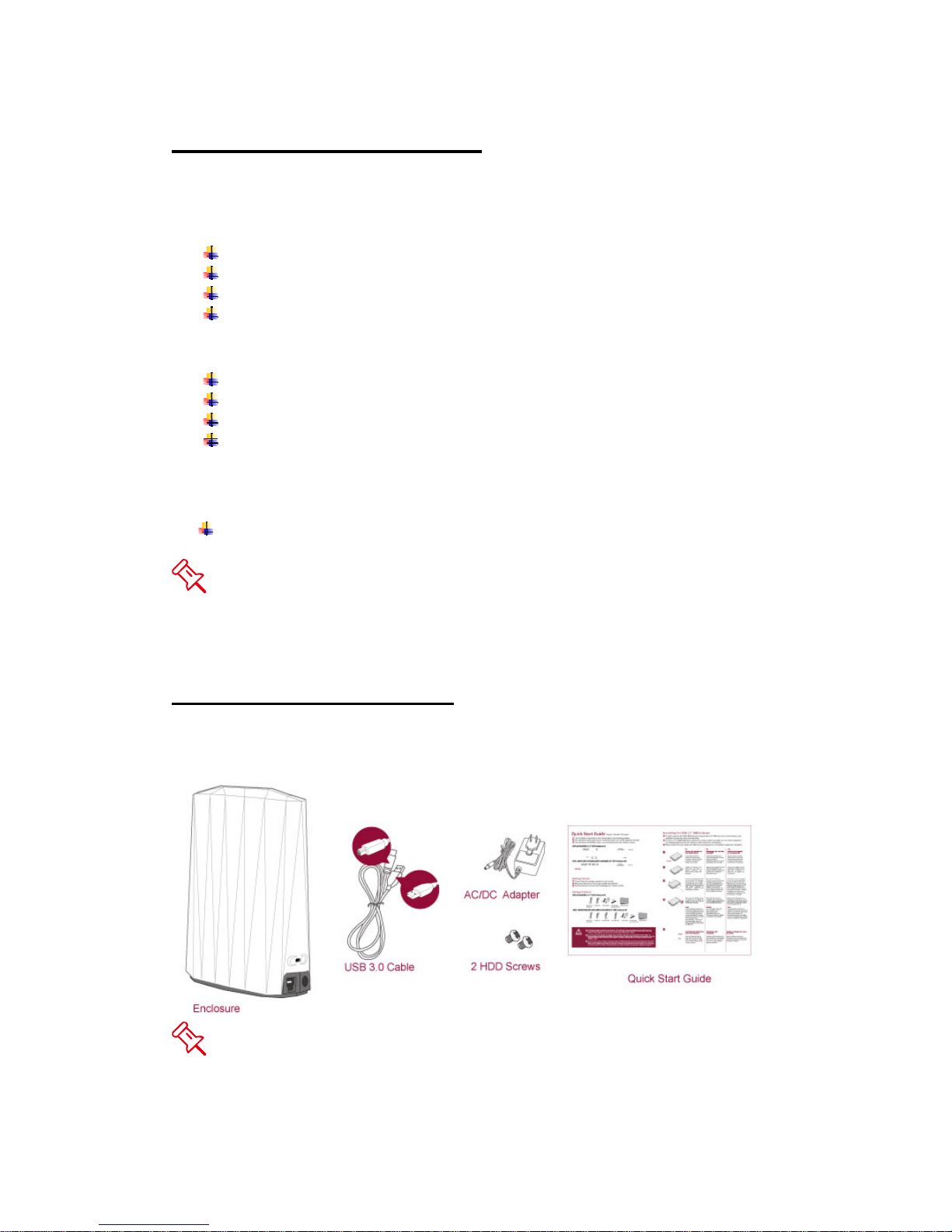
To get started, please review the package contents for the chosen model.
HU-M10J
Please keep all package contents and packaging material in the event
that the product must be returned.
Page 7
7
SYSTEM UNIT VIEWS
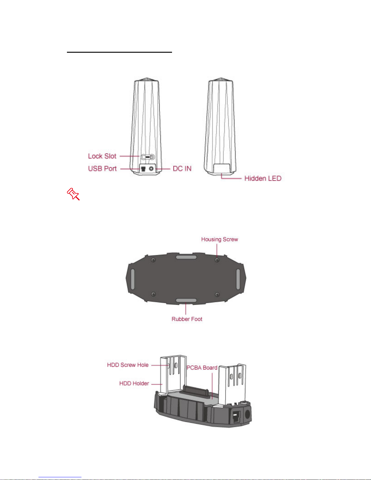
Rear/Front View
The hidden LED will indicate the current operating status by shining
downward onto the surface.
Bottom View
Inside View
Page 8
8
ASSEMBLING THE ENCLOSURE
To begin using the Crystal USB 3.0 3.5-inch HDD Enclosure, simply install a
3.5” SATA hard drive into the Enclosure by completing the following steps:
Partitioning and formatting operations will erase all existing data on the
hard drive. Remember to backup all existing data from the hard drive before
performing any partitioning or formatting operations to prevent loss of data.
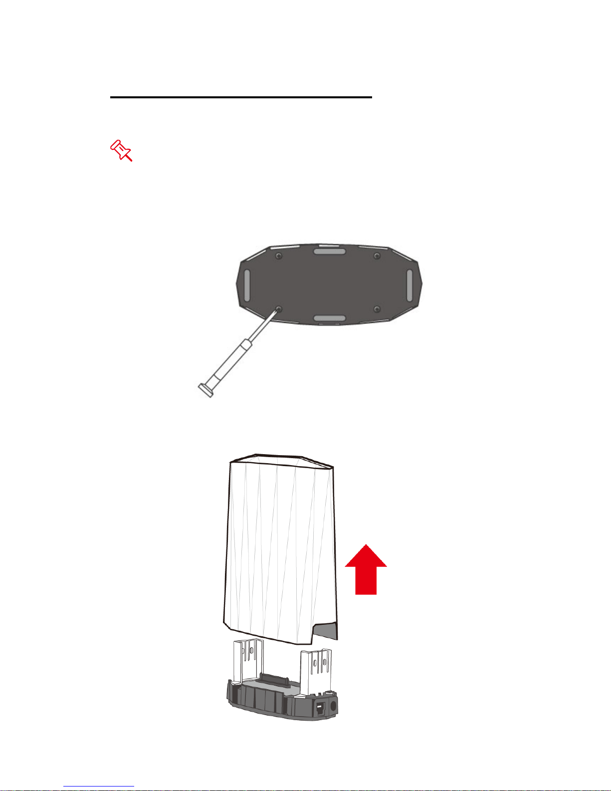
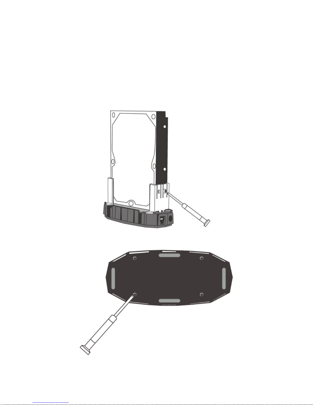
1. Turn the Enclosure with its Bottom View facing you. Use a Philips Screw
Driver and unscrew the four (4) larger Housing Screws.
2. After removing the four (4) larger Housing Screw, turn the Enclosure back
to upright standing position with its Rear View facing you. Hold the Bottom
Base with one hand and pull upward on the Housing Case with the other
hand.
Page 9
9
Once the Housing Case is removed, the PCBA board (Printed Circuit Board)
and two (2) HDD Holders should be already securely installed onto the
Bottom Base. See Inside View for reference. Also, find the two (2) HDD
Screws included inside the package.
3. Then, place the 3.5-inch SATA hard drive into the two (2) HDD Holder slot
on top of the Bottom Case. Make sure the hard drive and PCBA are
aligned properly. Use a Philips Screw Driver and screw in one (1) HDD
Screws on each side of the HDD Holder. Tighten the HDD Screws
securely to ensure that proper alignment is maintained.
4. Once completed, replace the Housing Case back onto the Bottom Base
and push downward. Use a Philips Screw Driver and re-screw the four (4)
Housing Screws back onto the Bottom Base.
5. Now, the Enclosure Unit is ready for connection to a computer!
Page 10
10
PUTTING ON & SWITCHING POWER PLUG ON
AC/DC ADAPTER
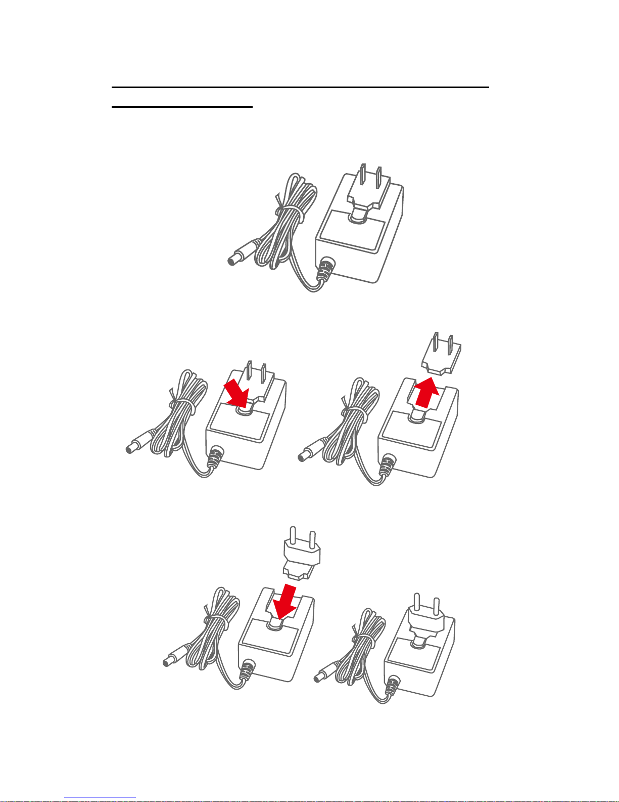
1. Find the AC/DC Adapter in the package. The package may include
different types of plug heads vary by region.
2. Press the click release and slide the existing Power Plug from the AC/DC
Adapter.
3. Slide the selected Power Plug onto the AC/DC adapter. Now, it is ready to
be used!
Page 11
11
CONNECTING THE ENCLOSURE UNIT TO A
COMPUTER
Complete the following steps to connect the Enclosure Unit to a host
computer:
The Enclosure Unit should only be connected to a host computer via one
interface at a time. Connection of the Enclosure Unit to a computer via two or
more interfaces simultaneously is not recommended.
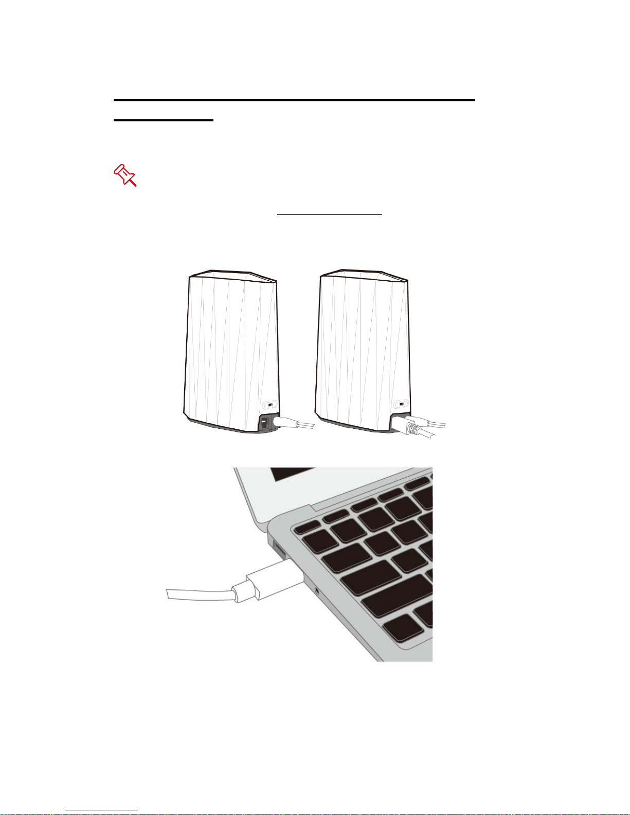
1. First, connect the AC/DC Adapter and the interface cable into the
corresponding ports of Enclosure Unit. Next, insert the plug end of the
AC/DC Adapter into an electrical plug.
2. Then, insert the interface cable to the corresponding port of the host
computer.
3. Once connected, the host computer should automatically detect the
external Enclosure Unit and the hard drive should begin powering up.
When the hard drive is powering up, the hidden LED will be blue. When
the hard drive is being accessed, the hidden LED will flash in blue.
Page 12
12
LED STATUS
LED COLOR STATUS
BLUE
POWER ON
FLASHING BLUE
DATA ACCESS
SAFE REMOVAL OF THE ENCLOSURE
Safe removal of the Enclosure Unit from the host controller is highly
recommended. In order to safely remove your Enclosure Unit from the host
controller, you would need to eject the device on your host controller system.
If using a Mac System, safe removal of the Enclosure from the host for
all interfaces is necessary.
EXTERNAL BOOTUP
External Bootup may be required if the user has two different operating
systems set up in both the host computer and the Enclosure.
PC
The External Bootup with different interface:
OS \ Interfaces USB 2.0/3.0
Windows
No
DOS
Yes
Linux
No
MAC
The External Bootup varies with different platform and interfaces:
Platform \ Interfaces USB 2.0/3.0
Power PC CPU
(G4 or Later)
No
CoreDuo
Yes
Intel-based
CPU
Core2Duo Or Later
Yes
Page 13

13
Q&As
Hard Drive Capacity
Q: My hard drive is at least 2TB or above, will the Enclosure be able to
support the gigantic storage capacity?
A: Yes, the Enclosure will be able to support any hard drive over 2TB size
capacity.
Q: I would like to format my hard drives with the FAT (a.k.a. File Allocation
Table) format, which can be read and written by both Mac and PC. Is there
any limitation on its capacity?
A: Yes, please check the table below for reference.
File
System
NTFS FAT32 FAT
(Format by
Win2000/WinXP)
FAT16
Capacity
Limitation
Vista: 16384TB
XP: 2TB
Windows: 32GB
Mac: 2TB
4GB 2GB
Discrepancy in Reported & Actual Size Capacity
Q: If I have a 750GB hard drive, why does the Enclosure only recognizes the
hard drive available space as to be less than 750GB?
A: Many customers are confused by their host systems when it reports a
discrepancy between reported capacity and actual capacity. Several factors
can come into play when your host system views and reports the capacity of a
hard drive. There are actually two different numbering systems used to
express units of storage capacity:
Binary, which says that a kilobyte is equal to 1024 bytes; and
Decimal, which says that a kilobyte is equal to 1000 bytes.
Most commonly used to display storage capacity is in Decimal. The
surprising fact is that even though it seems like you will have more bytes
under Binary, the Decimal calculation system actually presents a greater
storage capacity. More information on capacity issues can be found at the
Seagate website under FAQs.
http://www.seagate.com/ww/v/index.jsp?locale=enUS&name=Storage_Capacity_Measurement_Standards__Seagate_Technology&vgnextoid=9493781e73d5d010VgnVCM100000dd040
90aRCRD
Page 14

14
Page 15
15
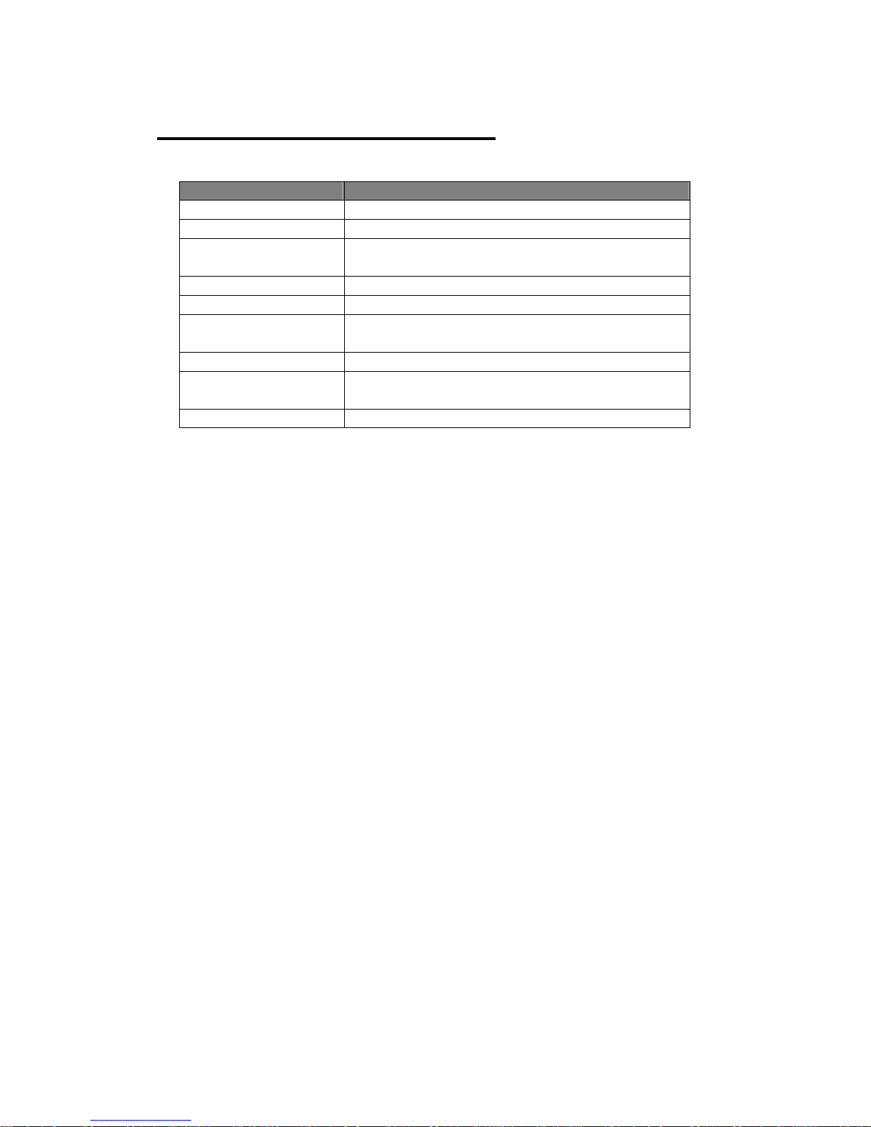
APPENDIX: SPECIFICATIONS
Model Name HU-M10J
Connector
USB 2.0/3.0 x 1
HDD Support
3.5” SATA hard drive
Data Transfer Speed
USB 3.0: up to 5Gbits/s
USB 2.0: up to 480Mbits/s
System Material
Plastic casing
Status Indicator
Power On / Access
Power Supply
Output: 12V/1.5A, Input: 100~240V
Universal AC/DC adapter
Dimension
131 (L) x 63 (W) x 180 (H) mm
Weight (without hard
drive)
220 g
Certification
CE, FCC, ErP/EuP
 Loading...