

Page 1
Intelligent Data Logging Products
DT80 Range
DT80/81/82/85
Series 1,2,3 & 4
Includes CEM20
User's Manual
A complete guide to:
• data acquisition
• data logging
• programming
• sensor wiring
• communications
Page 2

DT80 Range User’s Manual
Domain
Applicable Standards
IC
CFR47 FCC Part 15, Subpart B (Class A)
China RoHs 2 – models without WiFi / Modem
Refer to China RoHs table below
© Copyright 2005-2017 Thermo Fisher Scientific Australia Pty Ltd ABN 52 058 390 917
UM-0085-B10
Warranty
Thermo Fisher Scientific Australia Pty Ltd (“Thermo Fisher”) warrants the instruments it manufactures against defects in
either the materials or the workmanship for a period of three years from the date of delivery to the original customer.
This warranty is limited to, and purchaser’s sole remedy for a breach of this warranty is, the replacement or repair of
such defects, without charge, when the instrument is returned to Thermo Fisher or to one of its authorized dealers
pursuant to Thermo Fisher’s return policy procedures.
The obligations set forth above shall be void with respect to any damage to the instrument resulting from accident,
abuse, improper implementation or use, lack of reasonable care, loss of parts, force majeure, or any other third party
cause beyond Thermo Fisher’s control. Any installation, maintenance, repair, service, or alteration to or of, or other
tampering with, the instruments performed by any person or entity other than Thermo Fisher without its prior written
approval, or any use of replacement parts not supplied by Thermo Fisher, shall immediately void and cancel all
warranties with respect to the affected instruments.
Thermo Fisher shall not be liable for any incidental, indirect, special, punitive or consequential loss or damages resulting
from or arising out of the use of the instrument, In no event shall Thermo Fisher’s liability with respect to the instrument,
the use thereof, this warranty statement or any cause of action related thereto, under any circumstances exceed the
purchase price of the instrument actually paid by purchaser.
Where Thermo Fisher supplies to the customer equipment or items manufactured by a third party, then the warranty
provided by the third party manufacturer shall pass through to purchaser, but only to the extent allowed by the original
manufacturer or third party supplier.
EXCEPT AS EXPRESSLY PROVIDED IN THIS WARRANTY STATEMENT, THERMO FISHER DISCLAIMS ALL
OTHER WARRANTIES, WHETHER EXPRESS OR IMPLIED, ORAL OR WRITTEN, WITH RESPECT TO THE
INSTRUMENTS, INCLUDING WITHOUT LIMITATION ALL IMPLIED WARRANTIES OF MERCHANTABILITY OR
FITNESS FOR ANY PARTICULAR PURPOSE. THERMO FISHER DOES NOT WARRANT THAT THE INSTRUMENTS
ARE ERROR-FREE OR WILL ACCOMPLISH ANY PARTICULAR RESULT. ANY ADVICE OR ASSISTANCE
FURNISHED BY THERMO FISHER IN RELATION TO THE INSTRUMENTS SHALL NOT GIVE RISE TO ANY
WARRANTY OR GUARANTEE OF ANY KIND, AND SHALL NOT CONSTITUTE A WAIVER BY THERMO FISHER.
The Purchaser shall be solely responsible for complying with all applicable local, state and Federal laws with respect to
the installation, use and implementation of the equipment.
Trademarks
dataTaker is a registered trademark of Thermo Fisher Scientific Australia Pty Ltd
Adobe® Flash ® Player. Copyright © 1996 – 2006 Adobe Systems Incorporated. All Rights Reserved. Protected by U.S.
Patent 6,879,327; Patents Pending in the United States and other countries. Adobe and Flash are either trademarks or
registered trademarks in the United States and/or other countries.
All other brand and product names are trademarks or registered trademarks of their respective holders.
Regulatory Notices
This equipment has been tested and found to comply with the limits for a Class A digital device, pursuant to part 15 of
the FCC Rules. These limits are designed to provide reasonable protection against harmful interference when the
equipment is operated in a commercial environment. This equipment generates, uses, and can radiate radio frequency
energy and, if not installed and used in accordance with the instruction manual, may cause harmful interference to radio
communications. Operation of this equipment in a residential area is likely to cause harmful interference in which case
the user will be required to correct the interference at his own expense.
Please refer to the following table and information for compliance requirements of the DT80 Series, CEM20 and internal
devices.
Safety (Product with Integrated Modem)
EMC
EN 60950.1:2006 +Amdt 11(2009), A1(2010), A12(2011) & A2(2013)
AS/NZS 60950.1:2011 +Amdt 1(2012)
EN 55022:2010 + AC:2011
EN 55024:2010
EN 61000-3-2: Ed. 4.0 (2014)
EN 61000-3-3: Ed. 3.0 (2013)
ETSI EN 301 489-1 V1.9.2 (2011-09)
FCC CFR47 FCC Part 15, Subpart B (Class A)
UM-0085-B09 DT80 Range User Manual Page 2
RG
Page 3

FCC / IC Statements
零件或部件名称
有害物质或元素
铅
汞
镉
Hexavalent
六价铬
Polybrominated
多溴联苯
Polybrominated
多溴二苯醚
0.1
0.01)
This equipment has been tested and found to comply with the limits for a Class A digital device, pursuant to part 15 of
the FCC Rules. These limits are designed to provide reasonable protection against harmful interference when the
equipment is operated in a commercial environment. This equipment generates, uses, and can radiate radio frequency
energy and, if not installed and used in accordance with the instruction manual, may cause harmful interference to radio
communications. Operation of this equipment in a residential area is likely to cause harmful interference in which case
the user will be required to correct the interference at his own expense.
Changes or modifications not expressly approved by the party responsible for compliance could void the user's authority
to operate the equipment.
Cet équipement a été testé et reconnu co nforme aux limites d'un appareil numérique de classe A, conformément à la
partie 15 des règles de la FCC. Ces limit es sont conçues pour fournir une prot ec tion raisonnable contre les interférences
nuisibles lorsque l'équipemen t est utilisé dans un environnement c ommercial. Cet équipement génère, utilise et peut
émettre de l'énergie radiofréquenc e et, s'il n'est pas installé et utilisé conformément au manuel d'instr uctions, peut
causer des interférences nuisibles aux communications radio. Le fonctionnement de cet équipement dans une zone
résidentielle est susceptible de causer des interférences nuisibles , auquel cas l'utilisateur devr a c orriger l'interférence à
ses propres frais.
Les changements ou modifications non expressément approuvés par la par tie responsable de la conformité pourraient
annuler l'autorisation de l'utilisateur d'utiliser l'équipement.
Dependent on model the product may contain
• Modem (DT80LM3, DT82EM3, DT85M3, DT85GLM3) – FCC ID: RI7HE910 / IC ID: 5131A-HE910
• WiFi Module (DT80W, DT80GW, DT85W, DT85GW) – FCC ID: XF6-RS9113SB / IC ID: 8407A-RS9113SB
China RoHs
Part or
Component
Name
Resistors
电阻
Standoffs
支座
Connectors
连接器
Fasteners
紧固件
Potentiometers
电位器
Memory Stick
记忆棒
Integrated Circuits
集成电路
Lead (Pb)
X O O O O O
X O O O O O
X O O O O O
X O O O O O
X O O O O O
X O O O O O
X O O O O O
Mercury (Hg)
Cadmium (Cd)
Hazardous Substances
Chromium (Cr(VI))
Biphenyls (PBB)
Diphenyl Ethers (PBDE)
This table is prepared in accordance with the provisions of SJ/T 11364.
本表格依据SJ/T 11364 的规定编制。
O : Indicates that the concentration of the hazardous substance in all homogeneous materials of the part is below the relevant
threshold of the GB/T 26572 standard.
O : 表示该有害物质在该部件所有均质材料中的含量均在 GB/T 26572 规定的限量要求以下。
X : Indicates that the concentration of the hazardous substance in at least one homogeneous material of the part is above the
relevant threshold of the GB/T 26572 standard.
X : 表示该有害物质至少在该部件的某一均质材料中的含量超出 GB/T 26572 规定的限量要求。
Marking Standard SJ/T 11364 requires this chart format for listed parts or components that exceed a maximum concentrated limit.
As a service to our customers, we are using the chart format to provide information regarding these part or components.
标识标准SJ / T 11364要求此图表格式列出超过最大浓度限制的零件或组件。作为对我们客户的服务,我们使用此图表格式提供有关
这些零件或组件的信息。
(Concentration limits are 0.1% for Lead, Mercury, Hexavalent Chromium, Polybrominated Biphenyls, Polybrominated Diphenyl
Ethers (excluding decaBDE), and 0.01% for Cadmium)
(铅,汞,六价铬,多溴联苯,多溴二苯醚(不包含十溴二苯醚)的浓度限制为
%,以及镉为
Environment Friendly Use Period (EFUP)
环保使用期限(EFUP)
UM-0085-B09 DT80 Range User Manual Page 3
RG
Page 4

Changes or modifications not expressly approved by the party responsible for compliance could void the user's authority
to operate the equipment.
Disposal of Product and Batteries
This product is subject to the EU Directive 2012/19/EU for Waste Electrical and Electronic Equipment
(WEEE). As such product must not be disposed of in general waste facilities. Please refer to local
regulations or contact your distributor on he to dispose this product in an environmentally friendly
manner.
Dispose of used batteries via an appropriate recycling facility only.
Warning
dataTaker products are not authorized for use as critical components in any life support system where failure of the
product is likely to affect the system’s safety or effectiveness.
Important: Firmware Version Covered in This Manual
This version of the dataTaker DT80 Range User’s Manual (UM-0085-B10) applies to the DT80 range of data loggers
(DT80, DT80G, DT80L, DT80LM3, DT80GL, DT80W, DT82E, DT82EM3, DT82I, DT85, DT85G, DT85L, DT85LM3,
DT85GL, DT85W, DT85GW, and DT85GLM3, Series 1, 2, 3 and 4) running Version 9.20 firmware.
UM-0085-B09 DT80 Range User Manual Page 4
RG
Page 5

Content
Content ...................................................................................................................... 5
Part A – The DT80 ...................................................................................... 14
DT80 Concepts ........................................................................................................ 14
What is the DT80? ...................................................................................................................................... 14
The DT80 Product Family ........................................................................................................................... 14
DT80-Friendly Software .............................................................................................................................. 18
About This Manual ...................................................................................................................................... 18
A Tour of the DT80's Interfaces .................................................................................................................. 18
Getting Started ............................................................................................................................................ 19
Sending Commands.................................................................................................................................... 20
Getting Help ................................................................................................................................................ 21
Designing Your Data Logging System ........................................................................................................ 21
Measurements ......................................................................................................... 22
What can the DT80 Measure? .................................................................................................................... 22
Analog Channels – Introduction .................................................................................................................. 22
Digital Channels – Introduction ................................................................................................................... 25
Serial Channels – Introduction .................................................................................................................... 25
Programming the DT80 ........................................................................................... 26
Typical Workflow ......................................................................................................................................... 26
USB memory devices .................................................................................................................................. 28
Format of Returned Data ........................................................................................ 30
Real-time data ............................................................................................................................................. 30
Logged Data ............................................................................................................................................... 31
Part B – Channels ...................................................................................... 33
Channel Definitions ................................................................................................ 33
Channel Numbers ................................................................................................... 33
Channel Number Sequence ........................................................................................................................ 34
Channel Types ......................................................................................................... 34
Internal Channel Types ............................................................................................................................... 37
Channel Options ..................................................................................................... 41
Overview ..................................................................................................................................................... 41
A Special Channel Option — Channel Factor ............................................................................................. 42
Multiple Reports .......................................................................................................................................... 42
Mutually Exclusive Options ......................................................................................................................... 42
Order of Application .................................................................................................................................... 43
Default Channel Options ............................................................................................................................. 43
Channel Option Table ................................................................................................................................. 44
Part C – Schedules .................................................................................... 48
Schedule Concepts ................................................................................................. 48
What are Schedules? .................................................................................................................................. 48
Schedule Syntax ......................................................................................................................................... 48
Types of Schedules ................................................................................................ 51
UM-0085-B09 DT80 Range User Manual Page 5
RG
Page 6

General-Purpose Report Schedules ........................................................................................................... 51
Immediate Report Schedules ...................................................................................................................... 56
Statistical Report Schedules ....................................................................................................................... 57
Working with Schedules ......................................................................................... 58
Entering Schedules into the DT80 (BEGIN–END) ...................................................................................... 58
Triggering and Schedule Order ................................................................................................................... 58
Changing a Schedule Trigger ..................................................................................................................... 59
Halting & Resuming Schedules ................................................................................................................... 59
Executing Commands in Schedules ........................................................................................................... 59
Time Triggers — Synchronizing to Midnight ............................................................................................... 60
Part D – Jobs .............................................................................................. 61
What is a Job? ............................................................................................................................................ 61
Entering a Job ............................................................................................................................................. 61
Loading an Existing Job .............................................................................................................................. 62
Job Structure ............................................................................................................................................... 62
Job Commands ........................................................................................................................................... 63
Startup Job .................................................................................................................................................. 64
ONINSERT Job ........................................................................................................................................... 64
Part E – Manipulating Data ....................................................................... 65
Scaling ..................................................................................................................... 65
Channel Factor ........................................................................................................................................... 65
Spans (Sn) .................................................................................................................................................. 65
Polynomials (Yn) ......................................................................................................................................... 66
Thermistor Scaling (Tn) ............................................................................................................................... 66
Intrinsic Functions (Fn) ................................................................................................................................ 67
Combining Scaling Options ......................................................................................................................... 67
Calculations ............................................................................................................. 67
Channel Variables (nCV) ............................................................................................................................ 67
Calculation Only Channels .......................................................................................................................... 69
Reference Channels ................................................................................................................................... 69
Expressions ................................................................................................................................................ 70
Running Average ........................................................................................................................................ 74
Derived Quantities .................................................................................................. 75
Rates and Integrals ..................................................................................................................................... 75
Edge Timing ................................................................................................................................................ 75
Statistical Channel Options .................................................................................... 76
Overview ..................................................................................................................................................... 76
Statistical Functions .................................................................................................................................... 77
Multi Value Statistical Options ............................................................................... 78
Histogram (Hx:y:m..nCV) ............................................................................................................................ 78
Rainflow Cycle Counting ............................................................................................................................. 79
Part F – Alarms .......................................................................................... 82
Alarm Concepts ....................................................................................................... 82
Alarm Commands ................................................................................................... 82
Alarm Number ............................................................................................................................................. 83
Alarm Condition .......................................................................................................................................... 83
Alarm Digital Action Channels ..................................................................................................................... 85
Alarm Action Text ........................................................................................................................................ 85
Alarm Communication Actions .................................................................................................................... 87
UM-0085-B09 DT80 Range User Manual Page 6
RG
Page 7

Alarm Action Processes .............................................................................................................................. 88
Alarm Records ......................................................................................................... 92
Real Time Alarm Return .............................................................................................................................. 92
Logging Alarms ........................................................................................................................................... 92
Polling Alarm Inputs ............................................................................................... 93
Part G – Logging and Retrieving Data ..................................................... 94
Logging Data ........................................................................................................... 94
Enabling and Disabling Data Logging ......................................................................................................... 94
How Data and Alarms are Stored ............................................................................................................... 94
Logging Options .......................................................................................................................................... 96
Factors Which May Prevent Logging .......................................................................................................... 96
Checking Logging Status ............................................................................................................................ 97
Retrieving Logged Data .......................................................................................... 98
Overview ..................................................................................................................................................... 98
LISTD – List Available Data ........................................................................................................................ 98
COPYD – Unload Data ............................................................................................................................. 101
DELD - Delete Logged Data ..................................................................................................................... 111
Background Commands ............................................................................................................................ 112
Obsolete Commands ................................................................................................................................ 113
The DT80 File System ........................................................................................... 114
Internal File System (B:) ............................................................................................................................ 114
External USB Devices (A:) ........................................................................................................................ 114
File Commands ......................................................................................................................................... 116
Data Recovery .......................................................................................................................................... 116
Part H – DT80 Front Panel ...................................................................... 118
Display ................................................................................................................... 118
Displaying Channels and Alarms .............................................................................................................. 118
Bar Graph ................................................................................................................................................. 119
Controlling what is shown on the display .................................................................................................. 119
Auto-scrolling ............................................................................................................................................ 120
Auto-acknowledge .................................................................................................................................... 120
Pop-up Messages ..................................................................................................................................... 120
Interactive Screens ................................................................................................................................... 120
Display Backlight ....................................................................................................................................... 120
User Defined Functions ........................................................................................ 121
Defining Functions .................................................................................................................................... 121
Selecting Functions ................................................................................................................................... 121
Default Functions ...................................................................................................................................... 121
Keypad operation .................................................................................................. 122
Special Key Sequences ............................................................................................................................ 122
Status Indicator Lights ......................................................................................... 122
Sample Indicator ....................................................................................................................................... 122
Disk Indicator ............................................................................................................................................ 122
Power Indicator ......................................................................................................................................... 122
Attn Indicator ............................................................................................................................................. 122
Part I – dEX ............................................................................................. 124
What is dEX? ............................................................................................................................................ 124
dEX vs. Classic Web Interface .................................................................................................................. 124
UM-0085-B09 DT80 Range User Manual Page 7
RG
Page 8

Connecting to the Web Interface ............................................................................................................... 124
dEX Home Page ....................................................................................................................................... 124
Starting dEX .............................................................................................................................................. 125
Browser Requirements .............................................................................................................................. 126
Back to the Main Menu (Home) ................................................................................................................ 126
dEX Configuration Builder ................................................................................... 126
Configure the logger ................................................................................................................................. 126
About Configurations................................................................................................................................. 126
Using the Configuration Builder ................................................................................................................ 126
Defining Schedules ................................................................................................................................... 128
Defining Channels ..................................................................................................................................... 130
Global Settings .......................................................................................................................................... 136
Managing Configurations .......................................................................................................................... 143
Logger Controls ........................................................................................................................................ 144
Preventing Configuration Changes ........................................................................................................... 144
dEX Web Interface ................................................................................................. 145
Using the Web Interface ............................................................................................................................ 145
Status Screens .......................................................................................................................................... 146
Data Retrieval ........................................................................................................................................... 148
Displaying Real-Time Measurements ....................................................................................................... 150
Command Window .................................................................................................................................... 157
Help ........................................................................................................................................................... 159
Customising the Web Interface ............................................................................ 160
Overview ................................................................................................................................................... 160
The Web Interface Configuration Tool ...................................................................................................... 160
Preventing Configuration Changes ........................................................................................................... 163
Enabling dEX User Level Authentication................................................................................................... 163
dEX Languages ........................................................................................................................................ 166
Classic Web Interface ........................................................................................... 167
Browser Requirements .............................................................................................................................. 167
Navigating the Web Interface .................................................................................................................... 167
Home Page ............................................................................................................................................... 167
Channels Page ......................................................................................................................................... 168
Status Page .............................................................................................................................................. 168
Files Page ................................................................................................................................................. 169
Help Page ................................................................................................................................................. 169
Customising the Classic Interface ....................................................................... 170
Web Application Programming Interface (API) .......................................................................................... 170
Server-Side Include (SSI) Directives ......................................................................................................... 170
Building A Custom Web Page ................................................................................................................... 173
Part J – Modbus Interface ...................................................................... 175
About Modbus ........................................................................................................................................... 175
Connecting to a Modbus Network ............................................................................................................. 175
Modbus Registers ..................................................................................................................................... 176
Putting It All Together ................................................................................................................................ 179
Part K – Communications ....................................................................... 182
Overview ................................................................................................................ 182
Services .................................................................................................................................................... 182
Protocols ................................................................................................................................................... 182
Physical Ports ........................................................................................................................................... 183
About the Communications Diagram ........................................................................................................ 183
UM-0085-B09 DT80 Range User Manual Page 8
RG
Page 9

The Command Interface ....................................................................................... 186
Connecting to the Command Interface...................................................................................................... 186
Command Interface Operation .................................................................................................................. 186
Detecting DT80 Presence ......................................................................................................................... 186
Password Protection ................................................................................................................................. 186
USB Port ................................................................................................................ 187
Configuring the USB Port .......................................................................................................................... 187
About DtUsb .............................................................................................................................................. 187
Installing DtUsb ......................................................................................................................................... 188
Using DtUsb .............................................................................................................................................. 191
USB Direct Serial Mode ............................................................................................................................ 192
Sleep Mode ............................................................................................................................................... 193
RS-232 Communications ...................................................................................... 193
Direct RS-232 Connection ........................................................................................................................ 193
RS-232 Flow Control ................................................................................................................................. 193
Sleep Mode ............................................................................................................................................... 194
Host RS-232 Port ................................................................................................... 195
Configuring the Host RS-232 Port ............................................................................................................. 195
Serial Sensor Port ................................................................................................. 196
Connecting to the Serial Sensor Port ........................................................................................................ 197
Configuring the Serial Sensor Port ............................................................................................................ 198
External Modem .................................................................................................... 200
Modem (Remote) RS 232 Connection ...................................................................................................... 200
Automatic Modem Detection ..................................................................................................................... 200
DT80-to-Modem Cable .............................................................................................................................. 200
Modem Initialisation .................................................................................................................................. 201
Powering the DT80’s Modem .................................................................................................................... 203
Modem Communications Operation .......................................................................................................... 203
Setting Up a Remote Connection .............................................................................................................. 204
Part L – Network Communications ........................................................ 205
TCP/IP Concepts ................................................................................................... 205
About TCP/IP ............................................................................................................................................ 205
About This Section .................................................................................................................................... 205
TCP/IP Parameters ................................................................................................................................... 206
Integrated Modem ................................................................................................. 207
Mobile Plans ............................................................................................................................................. 208
Getting Started .......................................................................................................................................... 210
Configuring the Integrated Modem ............................................................................................................ 211
Verifying Modem Operation ...................................................................................................................... 215
Troubleshooting and Advanced Configuration .......................................................................................... 217
Communications Sessions .................................................................................. 222
Session Timing ......................................................................................................................................... 222
Error handling ........................................................................................................................................... 224
Session Diagnostics .................................................................................................................................. 227
Ethernet Sessions ..................................................................................................................................... 229
Ethernet Communications.................................................................................... 231
Connecting to the DT80 Ethernet Port ...................................................................................................... 231
Ethernet Commands ................................................................................................................................. 233
How to set up Ethernet .............................................................................................................................. 235
Accessing the DT80 via the Internet ......................................................................................................... 238
WiFi Communications .......................................................................................... 240
UM-0085-B09 DT80 Range User Manual Page 9
RG
Page 10

WiFi Interface ............................................................................................................................................ 240
WiFi Commands ....................................................................................................................................... 240
Setting up WiFi Connection ....................................................................................................................... 244
PPP Communications ........................................................................................... 246
About PPP ................................................................................................................................................ 246
Setting up PPP .......................................................................................................................................... 246
Using PPP ................................................................................................................................................. 253
Network Services .................................................................................................. 254
Using the Network Command Interface .................................................................................................... 254
Using the DT80 FTP Server ...................................................................................................................... 255
Security .................................................................................................................. 257
Basic Security ........................................................................................................................................... 257
dEX Security ............................................................................................................................................. 258
Part M – Configuration ............................................................................ 260
Configuring the DT80 ............................................................................................ 260
Parameters ............................................................................................................................................... 260
Switches .................................................................................................................................................... 262
Profile Settings .......................................................................................................................................... 264
Command Server Timeout Profile ............................................................................................................. 269
Setting the System Time ........................................................................................................................... 269
Automatic Time Adjustment (NTP) ............................................................................................................ 270
Resetting the DT80 ................................................................................................ 273
Soft Reset ................................................................................................................................................. 273
Hard Reset ................................................................................................................................................ 273
Safe Mode ................................................................................................................................................. 274
Factory Settings ........................................................................................................................................ 274
Diagnostic Commands ......................................................................................... 275
TEST Command ....................................................................................................................................... 275
Event Logs ................................................................................................................................................ 276
STATUS Command .................................................................................................................................. 276
CHARAC Command ................................................................................................................................. 277
SERVICEDATA Command ....................................................................................................................... 277
Part N – Hardware & Power .................................................................... 278
Inputs and Outputs ............................................................................................... 278
Wiring Panel .............................................................................................................................................. 278
Left Side Panel .......................................................................................................................................... 279
Right Side Panel (DT8xM only) ................................................................................................................. 280
Right Side Panel (DT8xW only) ................................................................................................................ 280
Front Panel ............................................................................................................................................... 281
Rear Panel (DT8xG only) .......................................................................................................................... 281
Inside the DT80 ...................................................................................................... 282
Accessing the main battery (if fitted) ......................................................................................................... 282
Accessing the lithium memory backup battery .......................................................................................... 283
Installation ............................................................................................................. 285
Dimensions ............................................................................................................................................... 285
Operating Environment ............................................................................................................................. 285
Grounding ................................................................................................................................................. 286
Powering the DT80 ................................................................................................ 286
Power Subsystem ..................................................................................................................................... 286
UM-0085-B09 DT80 Range User Manual Page 10
RG
Page 11

External Power .......................................................................................................................................... 287
Internal Power ........................................................................................................................................... 288
Power Outputs .......................................................................................................................................... 290
Signal Output ............................................................................................................................................ 291
Internal Memory-Backup Battery ............................................................................................................... 291
Monitoring DT80 Power ............................................................................................................................ 292
Power Consumption ............................................................................................. 292
Power Consumption .................................................................................................................................. 292
Battery Life ................................................................................................................................................ 297
Minimising Power Consumption ................................................................................................................ 298
Sleep Mode ............................................................................................................ 300
About Sleep Mode .................................................................................................................................... 300
Wake Events ............................................................................................................................................. 300
Controlling Sleep ....................................................................................................................................... 300
Forced Sleep Mode ................................................................................................................................... 301
Part O – Sensors & Channels ................................................................. 302
Analog Channels ................................................................................................... 302
About the Analog Input Terminals ............................................................................................................. 302
Voltage ...................................................................................................................................................... 303
Current ...................................................................................................................................................... 306
4–20mA Current Loops ............................................................................................................................. 308
Resistance ................................................................................................................................................ 308
Bridges ...................................................................................................................................................... 311
Temperature – Thermocouples ................................................................................................................. 315
Temperature – Thermistors ....................................................................................................................... 317
Temperature – RTDs ................................................................................................................................ 319
Temperature – AD590 Series IC Sensors ................................................................................................. 319
Temperature – LM35 Series IC Sensors ................................................................................................... 321
Temperature – LM135 Series IC Sensors ................................................................................................. 322
Humidity Sensors ...................................................................................................................................... 323
Frequency ................................................................................................................................................. 323
Strain Gauges – Bridge ............................................................................................................................. 324
Strain Gauges – Vibrating Wire ................................................................................................................. 325
Strain Gauges – Carlson Meter ................................................................................................................. 327
Digital Channels .................................................................................................... 331
About the Digital I/O Channels .................................................................................................................. 331
Digital Inputs ............................................................................................................................................. 332
Digital Outputs .......................................................................................................................................... 333
Counters – Low Speed .............................................................................................................................. 337
Counters – High Speed ............................................................................................................................. 338
Phase Encoders ........................................................................................................................................ 340
Examples – Digital and Counters .............................................................................................................. 341
SDI-12 Channel ...................................................................................................... 342
About SDI-12 ............................................................................................................................................ 342
Testing and Configuring an SDI-12 Device ............................................................................................... 343
Reading Data from SDI-12 Devices .......................................................................................................... 343
Example .................................................................................................................................................... 345
Other Considerations ................................................................................................................................ 346
Troubleshooting ........................................................................................................................................ 346
Generic Serial Channel ......................................................................................... 348
Connecting to and Configuring the Serial Port .......................................................................................... 348
Serial Channel Commands ....................................................................................................................... 348
Serial Channel Operation .......................................................................................................................... 349
UM-0085-B09 DT80 Range User Manual Page 11
RG
Page 12

Control String – Output Actions ................................................................................................................. 351
Control String – Input Actions ................................................................................................................... 353
Control String – Example .......................................................................................................................... 355
Schedules ................................................................................................................................................. 355
Serial Sensor Direct Mode ........................................................................................................................ 356
Serial Interface Power Control .................................................................................................................. 357
Serial Channel Debugging Tools .............................................................................................................. 357
Serial Channel Examples .......................................................................................................................... 358
Modbus Channel ................................................................................................... 361
About Modbus ........................................................................................................................................... 361
Connecting Serial Modbus Sensors .......................................................................................................... 361
Connecting Network Modbus Sensors ...................................................................................................... 362
Reading Data from Modbus Devices ........................................................................................................ 363
MODBUS Channel Options ....................................................................................................................... 364
Block Transfers ......................................................................................................................................... 365
Examples .................................................................................................................................................. 366
Troubleshooting ........................................................................................................................................ 366
Technical Details & Troubleshooting .................................................................. 368
DT80 Analog Sub-System ......................................................................................................................... 368
Grounds, Ground Loops and Isolation ...................................................................................................... 372
Noise Pickup ............................................................................................................................................. 373
Self-Heating of Sensors ............................................................................................................................ 373
Getting Optimal Speed from Your DT80 ................................................................................................... 374
Part P – The CEM20 ................................................................................. 375
What is the CEM20? ................................................................................................................................. 375
Connecting CEM20s ................................................................................................................................. 375
CEM20 Addresses .................................................................................................................................... 377
Powering the CEM20 ................................................................................................................................ 377
Accessing CEM20 Channels ..................................................................................................................... 377
CEM20 Temperature Reference ............................................................................................................... 378
Troubleshooting ........................................................................................................................................ 378
Part Q – Reference ................................................................................... 379
DT80 Series Specifications .................................................................................. 379
Analog Inputs ............................................................................................................................................ 379
Digital Inputs and Outputs ......................................................................................................................... 380
High Speed Counter Inputs ....................................................................................................................... 381
Serial Channels ......................................................................................................................................... 381
Data Manipulation and Logging ................................................................................................................ 382
Communication Interfaces ........................................................................................................................ 382
Network (TCP/IP) Services ....................................................................................................................... 383
System ...................................................................................................................................................... 384
CEM20 Specifications ........................................................................................... 385
Command Summary ............................................................................................. 386
ASCII-Decimal Table ............................................................................................. 389
RS-232 .................................................................................................................... 392
Signals ...................................................................................................................................................... 392
Cables ....................................................................................................................................................... 392
Upgrading DT80 Firmware ................................................................................... 394
Recommended Preparation ...................................................................................................................... 394
Firmware Upgrade – USB Flash Device ................................................................................................... 395
UM-0085-B09 DT80 Range User Manual Page 12
RG
Page 13

Firmware Upgrade – Host USB or RS232 Port ......................................................................................... 395
Firmware Upgrade – Remote TCP/IP ....................................................................................................... 396
Reverting Back to Old Firmware ............................................................................................................... 396
In Case of Failed Upgrade ........................................................................................................................ 396
Upgrading Modem Firmware ..................................................................................................................... 396
Error Messages ..................................................................................................... 397
Standard Messages .................................................................................................................................. 397
Data Errors ................................................................................................................................................ 401
DT80 Abnormal Resets ............................................................................................................................. 402
Glossary ................................................................................................................. 403
Safety Information ................................................................................................. 414
General ..................................................................................................................................................... 414
Models with Internal Lead Acid Battery ..................................................................................................... 414
Models with Integrated Modem/ Integrated WiFi ....................................................................................... 414
Index ....................................................................................................................... 415
UM-0085-B09 DT80 Range User Manual Page 13
RG
Page 14
Part A – The DT80
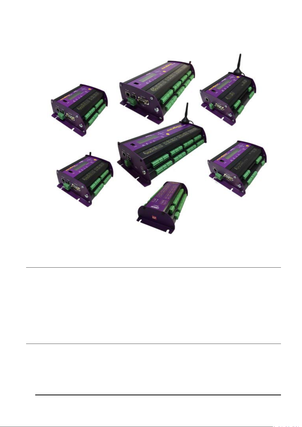
Figure 1: The dataTaker DT80, DT80W (left); DT85W, DT85GM, CEM20 (centre), DT82EM, DT82I (right)
DT80 Concepts
What is the DT80?
The dataTaker DT80 range of data acquisition and logging instruments are tools to measure and record a wide variety of
quantities and values in the real world.
The web based dEX graphical user interface makes it quick and easy to define basic measurement tasks. Logged data
can then be easily extracted via a USB "memory stick", or downloaded using the web interface into files ready for import
into spreadsheets and data analysis tools.
The DT80 range of loggers also include a powerful programming language which allows complex systems to be
developed and monitored.
Extensive sensor support and communications options, and a rugged and low-power design, make the DT80 a very
flexible data logger.
The DT80 Product Family
Models
The DT80 product family includes the following models:
• The DT80 is a full-featured data logger,
• The DT82E is a low cost, low power logger designed for environmental applications.
UM-0085-B09 DT80 Range User Manual Page 14
RG
Page 15

• The DT82I is designed for industrial applications.
• The DT85 is an expanded and enhanced version of the DT80.
• The DT80L and DT85L are low power variants of the DT80 and DT85.
• The DT80W and DT85W are WiFi variant of the DT80 and DT85.
• The DT80G and DT85G GeoLoggers are designed for Geotechnical applications
• The DT80GW and DT85GW are WiFi variant of the DT80G and DT85G.
• The DT80GL and DT85GL are low power variants of the DT80G and DT85G.
• The DT82EM3, DT80LM3, DT85LM3 and DT85GLM3 contain an inbuilt GSM/EDGE/WCDMA cellular modem.
• The DT82EM2, DT80LM2, DT85LM2 and DT85GLM2 contain an inbuilt GSM/EDGE cellular modem.
• The CEM20 (Channel Expansion Module) is a 20-channel analog multiplexer which can be used to expand the
number of analog input channels on a DT80 or DT85.
All of these models operate in a similar way; the differences are mainly to do with the number of input channels and other
hardware features. Table 1 (P16) and Table 2 (P17) lists the main differences between each model.
Series 1, 2, 3 and 4
In January 2008, the original DT80, DT81 and DT85 models were superseded by enhanced Series 2 models. These
offered an all-new web based interface (dEX), additional power outputs, and more flexible analog input switching.
Series 3 models were introduced from October 2010. These supersede Series 2 and include enhanced resistance
measurement options and an isolated switched 5V power output.
Series 4 were launched from February 2017 and include increased voltage and resistance measurement ranges, flexible
12/ 5V power outputs and integrating with DAC converter to produce voltage/ current outputs as well as WiFi connectivity
support.
Along with DT80 Series 4 launch the new CEM20 Series 2 has also been released. In CEM20 Series 2 all mechanical
relays has been replaced by opto-relays . As result all audible noise from the mechanical relay switching was eliminated.
Series 2, 3 and 4 units are clearly labelled as such on the front panel.When a logger model number is displayed, the
series is shown as a suffix, e.g. "DT85L-3" is a Series 3 DT85L.
GeoLoggers
The DT80G/GL and DT85G/GL "GeoLoggers" are equivalent to the DT80 and DT85, but also include direct support for
vibrating wire strain gauges, which are widely used in geotechnical applications; see Strain Gauges – Vibrating Wire
(P325). Throughout this manual, references to the DT80 and DT85 also refer to the DT80G and DT85G respectively,
unless otherwise noted.
Low Power Models
Most DT80 models include an internal 6V lead acid battery. However the low power "L" and "E" models do not include
an internal battery and are instead optimised for operation with an external battery (often solar charged). Throughout this
manual, references to the DT80 and DT85 also refer to the DT80L and DT85L respectively, unless otherwise noted.
Modem Models
The "M" models (DT82EM, DT80LM, DT85LM, DT85GLM) include an integrated cellular modem, which provides a
convenient wireless solution for control of the DT80 and data retrieval. The "M3" models support 2G and 3G networks
(GSM/ GPRS/ EDGE/ WCDMA), while the "M2" models support 2G only (GSM/ GPRS/ EDGE). Apart from this
difference, the M2 and M3 variants operate identically.
WiFi Models
The "W" models (DT80W, DT80GW, DT85W, DT85GW) include an integrated WiFi interface, which provides a
convenient wireless solution for control of the DT80 and data retrieval. See WiFi Communications (P240).
Channel Expansion Module
The CEM20 is an analog multiplexer designed to work with a DT80 or DT85 Series 2 logger and later revisions. It
provides an easy way to expand the number of input channels. Up to 16 CEM20 modules can be connected to a DT85,
giving a total of 320 input channels. See The CEM20 (P375).
Note: In this manual, the term DT80 (italics) is used to refer to all products (DT80, DT81, DT82 and DT85; Series 1, 2, 3 and 4). If a
feature or behaviour is specific to a particular model, this will be made clear in the text.
UM-0085-B09 DT80 Range User Manual Page 15
RG
Page 16
Feature
discontinued models
current models
Analog input channels
1 5 16 1 2 2 5 5 16
16 2 2 2 2 5 5 5 5 5 5
16
16
16
16
16
16
16
16
Fully isolated analog input pairs (+- and *#
terminals switched independently)
2-wire resistance measurements on *#, +# and # terminal pairs
Vibrating wire strain gauge support
- - - - - - - - - - - - - - - - - - - -
CEM20 modules supported
- - - - - - 5 5 16
16 - - - - 5 5 5 5 5 5
16
16
16
16
16
16
16
16
Digital I/O channels (open-drain outputs)
3 4 4 3 3 4 4 4 4 4 3 3 3 4 4 4 4 4 4 4 4 4 4 4 4 4 4
4
Digital I/O channels (logic outputs / SDI-12)
1 4 4 1 1 - 4 4 4 4 1 1 1 - 4 4 4 4 4 4 4 4 4 4 4 4 4 4 High speed counter inputs
4 4 4 4 4 4 4 4 4 4 4 4 4 4 4 4 4 4 4 4 7 4 7 7 7 4 7
7
Phase encoder inputs
1 2 2 1 - 2 2 2 2 2 - - - 2 2 2 2 2 2 2 3 2 3 3 3 2 3
3
RS232/422/485 communications port
-
-
-
- - -
RS232 communications port
-
-
-
-
-
- -
-
USB communications port
-
-
- - -
-
Ethernet port
Integrated GSM/GPRS/EDGE/WCDMA modem
- - - - - - - - - - -
- - - - - - - - - - - -
-
Integrated GSM/GPRS/EDGE modem
- - - - - - - - - - -
- - - - -
- - - - -
-
-
-
USB memory device port
Switched 12V power output
-
-
Unswitched external power output
-
-
- - - - -
- - - - - - - - -
-
Switched isolated 5V power output
- - - - - - - - -
-
Battery charger for internal/external battery
-
- - -
- - -
-
- - - - -
-
Internal battery (capacity in Ah)
1.2
1.2
4.0
1.2 - 1.2
1.2 - 4.0
4.0 - - - 1.2
1.2 - - - - - 4.0
4.0 - - - - - -
Modbus master function
-
-
-
- - -
LCD display & keypad
-
-
Status LEDs
4 3 4 4 4 4 4 4 4 4 4 4 4 4 4 4 4 4 4 4 4 4 4 4 4 4 4
4
Classic web interface (HTML)
dEX Enhanced web interface (Flash)
- - -
WiFi Connectivity
- - - - - - - - - - - - - - - - - - - - - - - - - - -
-
Voltage/ Current Output
- - - - - - - - - - - - - - - - - - - - - - - - - - -
-
DT81-1
DT80-1
DT85-1
DT81-2
DT82E-2
DT82I-2
DT80-2
DT80G-2
DT85-2
DT85G-2
DT82E-3
DT82EM2-3
DT82EM3-3
DT82I-3
DT80-3
DT80G-3
DT80L-3
DT80LM2-3
DT80LM3-3
DT80GL-3
DT85-3
DT85G-3
DT85L-3
DT85LM2-3
DT85LM3-3
DT85GL-3
DT85GLM2-3
DT85GLM3-3
- -
- - - - - - - - - -
Table 1: Feature listing for DT80 data logger Series 3 and older
UM-0085-B09 DT80 Range User Manual Page 16
RG
Page 17
Feature
current models
Analog input channels
2 2 2 5 5 5 5 5 5 5 16
16
16
16
16
16
16
16
Fully isolated analog input pairs (+- and *#
terminals switched independently)
2-wire resistance measurements on *#, +# and -#
terminal pairs
Vibrating wire strain gauge support
- - -
- -
- - - -
-
-
CEM20 modules supported
- - - 5 5 5 5 5 5 5 16
16
16
16
16
16
16
16
Digital I/O channels (open-drain outputs)
3 3 4 4 4 4 4 4 4 4 4 4 4 4 4 4 4
4
Digital I/O channels (logic outputs / SDI-12)
1 1 - 4 4 4 4 4 4 4 4 4 4 4 4 4 4 4 High speed counter inputs
4 4 4 4 4 4 4 4 4 4 7 4 7 7 4 7 7
4
Phase encoder inputs
- - 2 2 2 2 2 2 2 2 3 2 3 3 2 3 3
2
RS232/422/485 communications port
-
-
RS232 communications port
-
-
- -
USB communications port
- - -
Ethernet port
Integrated GSM/GPRS/EDGE/WCDMA modem
- - - -
- - - - - -
- - -
-
Integrated GSM/GPRS/EDGE modem
- - - - - - - - - - - - - - - - -
-
USB memory device port
Switched 12V power output
Unswitched external power output
- - - - - - - - -
-
Switched isolated 5V power output
- - - - - - - - - - - - - - - - - - Battery charger for internal/external battery
-
-
- - -
- - -
-
Internal battery (capacity in Ah)
- - 1.2
1.2 - - - -
1.2 - 4.0
4.0 - - - -
4.0
4.0
Modbus master function
-
-
LCD display & keypad
Status LEDs
Classic web interface (HTML)
dEX Enhanced web interface (Flash)
WiFi Connectivity
- - - - - - -
-
- - - - -
-
Voltage/ Current Output
-
-
DT82EM3- 4
DT82I- 4
DT80- 4
DT80G- 4
DT80L- 4
DT80LM3- 4
DT80GL- 4
DT80W-4
DT80GW-4
DT85- 4
DT85G- 4
DT85L- 4
DT85LM3- 4
DT85GL-3
DT85GLM3- 4
DT82E- 4
DT85W-4
DT85GW-4
Table 2: Feature listing for DT80 data logger Series 4
UM-0085-B09 DT80 Range User Manual Page 17
RG
Page 18

DT80-Friendly Software
Programming and Configuration
There are three main ways to set up and program the DT80.
• dEX is a web based application for programming and monitoring DT80 Series 2/ 3/ 4 data loggers. dEX is built
into the logger (no installation required) and runs in your web browser. It provides a totally graphical interface,
which means that knowledge of the dataTaker programming language is not required. Channels and schedules
are defined simply by clicking on icons and making selections from menus and dialog boxes; dEX will then
generate the required DT80 program and load it onto the logger.
• Alternatively, commands entered interactively and then sent to the DT80 via one of its comms ports or a TCP/IP
network. This allows full access to the DT80's capabilities. DeTransfer, or the enhanced web interface's
command window, are the best tools for the job here. They both have separate send and receive windows, a
macro facility, and many other useful features. A standard terminal program (e.g. HyperTerminal) can also be
used.
• Finally, you can develop a DT80 program off-line (e.g. using a text editor), then transfer it to the DT80 using a
USB memory device or send it as a file using DeTransfer.
Viewing Data and Status
Once the DT80 has been set up, there are a number of options for retrieving data and monitoring status:
• The DT80's inbuilt web interface (dEX) provides a convenient way to access current data values and status
information from any web browser. dEX is available on Series 2, 3 and 4 loggers.
• A simple HTML-based web interface is also provided on all loggers. This can be customised if required to
provide an application-specific user interface. This interface is designed to operate efficiently on slow
communications networks or on portable devices with a small display screen.
• DeTransfer can be used to view real-time and logged data in text format.
• dataTaker Instrument driver for LabVIEW™ is a set of drivers and documentation which allows dataTaker
data loggers to be incorporated in a LabVIEW environment. LabVIEW is National Instruments' industry-leading
graphical software development environment for measurement and automation applications.
All software is provided on the CD supplied with your DT80, and updates are available from the dataTaker website,
www.datataker.com (Support/ Downloads section).
About This Manual
This manual is intended for all users of the DT80. It describes:
• how to connect sensors and other devices to the DT80's input and output channels.
• how to program the DT80 to collect and return data as required.
• how to manage the data that the DT80 collects.
The main focus of this manual will be on directly programming the DT80 using its command language. However, most of
the concepts discussed here also apply when building programs using tools such as dEX.
A Tour of the DT80's Interfaces
The DT80's interfaces with the outside world are grouped into three main areas: user interface (top), sensor interface
(front) and communications interface (side). See also Inputs and Outp uts (P278).
User Interface
On the top panel of the DT80 you will find controls which allow the user to interact with the unit during operation – without
requiring a host computer:
• A 2-line LCD display shows status messages, measured values, and a menu of pre-defined functions (not
DT81)
• Six keypad buttons allow the user to navigate between the various displayed options (not DT81)
• Four status LEDs are provided – the blue Sample LED flashes each time a measurement is taken, the green
Disk LED indicates internal flash disk activity, the red Attn LED indicates various warning conditions, and the
green Power LED flashes at 3 second intervals while the logger is powered and not in low "sleep" mode. The
duty cycle of the flash indicates whether the logger is externally powered (long flashes) or running from its
internal battery (short flashes).
Note: Power LED is not present on DT80 Series 1.
• A USB socket allows connection of a USB memory device, which provides a convenient way to retrieve data
from the DT80 (or load a program onto it).
UM-0085-B09 DT80 Range User Manual Page 18
RG
Page 19

Sensor Interface
On the sloping front panel of the DT80 there are two rows of terminal blocks – digital channels on the left, analog
channels on the right. The green terminal blocks can be quickly unplugged from the DT80 without unscrewing the sensor
cabling. This interface includes:
• 8 digital input/ output/ counter channels (1D–8D), 4 of which are SDI-12 compatible (DT82I: 4 channels; DT81/
82E: 4 channels, one of which is SDI-12 compatible)
• an input to wake the DT80 from low power "sleep" mode (WK)
• 4 high speed counter inputs (7 on DT85/ 85L Series 3) (1C–4C)
• 2 phase encoder inputs, shared with the counter inputs connected) (1PE–2PE) (one phase encoder input on
DT81, none on DT82E, 3 on DT85/ 85L Series 3)
• a pair of voltage free relay contact outputs (RELAY A and B)
• a general purpose switched 12V 150mA power output (12V) (DT80/ 81/ 82E and DT85 Series 2/3 only)
• a general purpose switched 12V/5V 300mA power output (12V/5V) (DT80/ 82E, DT85 Series 4 only)
• a general purpose current limited (300mA) power output (PWR OUT), which is derived from the external power
input (DT85 only)
• an isolated switched 5V power output (5V SW) (Series 3 only)
• an isolated programmable 16-bit voltage and current output (V/I DAC) (Series 4 only)
• digital / power ground terminals (DGND)
• an RS232/422/485 compatible serial port (Tx, Rx, RTS and CTS) (not present on DT81/ 82E)
• a number of analog input channels (5 channels for DT80, 1 channel for DT81, 16 channels for DT85)
• an external excitation input (EXT *)
• isolated analog ground terminals (AGND on DT80/81, EXT# on DT80 Series 2 and DT85)
Note: early production DT80 models only had 4 analog inputs
Communications/ Power Interface
On the left side panel you have a variety of connectivity options:
• 10-Base-T Ethernet for connection to a host computer or local area network
• USB for high speed connection to a host computer (not present on DT82)
• RS232 for connection to host computer or modem (not present on DT8xM)
• two alternative DC power connectors – a standard plug-pack socket (DC jack) and a 4-pin terminal block (2-pin
for DT82E/ 80L/ 85L)
For more details, see Communications (P182)
Wireless Modem Interface (DT8xM only)
On the right side panel are the integrated modem interface:
• SIM card slot (subscriber identity module)
• red status LED
• coaxial screw connector for optional "receive diversity" antenna (DT8xM3 only)
• coaxial screw connector for main antenna.
A threaded earth point is also available on both left and right side panels. See Grounding (P286).
WiFi Interface (DT8xW only)
On the right side panel are the integrated WiFi interface:
• coaxial screw connector for main antenna.
A threaded earth point is also available on both left and right side panels. See Grounding (P286).
Getting Started
Power
Powering the DT80 (P286) discusses the ways to provide power to the DT80. The simplest option is to plug in the
supplied AC adaptor.
All DT80 models except the DT82E include an internal 6V lead-acid battery which can power the logger if the main
external supply is interrupted.
Important: The DT80 is shipped with its main internal battery disconnected. We recommend the battery is connected as soon as
practical so that it can charge from the mains adaptor or other external power source. This is achieved by simply plugging the green
power connector, see Powering the DT80 (P286).
UM-0085-B09 DT80 Range User Manual Page 19
RG
Page 20

Switch On!
When power is connected, you should observe:
• the LCD backlight switches on (DT80/ 85), and the green Power LED starts flashing
• a brief clicking sound as the unit performs an initial self-calibration
• DT80 restarted / Power loss is displayed on the LCD
• the front panel LEDs flash a few times then the red Attn LED continues to flash.
The DT80 is warning you that its power has been interrupted. Press any of the front panel keys to clear this indication.
The Attn LED should stop flashing and the display should now read: DT80 V9.20 / No current job. This indicates
that:
• the version of DT80 firmware in use is "9.20" (this number may vary), and
• no user program (or "job") has been loaded
The DT80 is now idle and waiting for instructions.
Connecting to a Host Computer
In order to program the DT80, it is generally necessary to connect it to a "host" computer. The easiest option here is to
use the supplied USB cable, or, for the DT82E/82I, the supplied Ethernet cable. Other options are to use a "null-modem"
(cross-over) RS232 cable, or to connect the logger to an Ethernet network. See Communications (P182) for more details
of the different communications options.
Very briefly, connecting the DT80 via USB involves the following steps:
1. Install the supplied DtUsb driver software. This allows you to access to DT80's network services via a USB
connection.
2. Connect the USB cable between the DT80 and the PC.
3. The Windows "New Hardware Found" wizard will then run automatically (if required) to complete the installation
of the necessary drivers.
4. Your default web browser will then be launched automatically and the dEX home page will be displayed.
To connect to the DT80 using Ethernet:
1. Connect the Ethernet cable between the DT80 and the PC, or between the DT80 and a socket on your
computer's local area network.
2. Use the DT80 keypad to scroll down to the "Ethernet" screen. Check that a valid IP address is displayed, e.g.
169.254.3.202
3. Launch your web browser and type the logger's IP address into the address bar. The dEX home page should
be displayed.
The above is only a brief overview. See USB Port (P187) for detailed, step by step instructions.
As an alternative to the dEX web-based interface, you can also install the supplied DeTransfer software, which can be
used to send the text-based commands described in this manual to the logger. DeTransfer can operate over a direct
RS232/ USB connection or a network connection, and will work with any logger model.
The remainder of this manual will assume you have successfully established a connection between the host PC and the
DT80.
Sending Commands
The DT80 is programmed by sending it textual commands. These commands may be either:
• manually entered (using DeTransfer, or the Command screen in dEX), or
• generated by the dEX configuration builder, based on details entered using its graphical user interface controls.
Commands are executed by the DT80 only after it receives a carriage-return character (↵).
Commands are not case-sensitive; that is, they may be entered using either uppercase or lowercase characters.
In this manual all commands are shown in UPPERCASE. Responses from the DT80 are shown like this.
After receiving a command, the DT80 will normally echo the command, after converting it to uppercase. After a command
has been processed, the DT80 will normally indicate that it is ready for the next one by transmitting a prompt string,
such as:
DT80>
Note: the DT80 does not echo each character as it is received.
Command echo and the prompt string can be turned off if required using the /e switch command, see Switches (P262).
The maximum length of a command is 1023 characters.
UM-0085-B09 DT80 Range User Manual Page 20
RG
Page 21

The general categories of commands are:
• channel definitions (P33) (e.g. 2TK("Kiln temp",FF4)) – these define what measurements are to be
taken, how they are to be acquired and how the measured values are to be presented.
• schedule definitions (P48) (e.g. RA(DATA:2MB)10S) – these define when a set of measurements are to be
taken and where the results are to be stored
• job management commands (P61) (e.g. BEGIN, END, SHOWPROG) – these allow a set of schedule and
channel definitions to be grouped into a single program, or "job", which can then be treated as a unit.
• data management commands (P94) (e.g. COPYD, LISTD) – these allow logged data points and alarms to be
retrieved, displayed or deleted.
• configuration commands (P260) (e.g. PROFILE) – these allow various aspects of the DT80's operation to be
adjusted to suit particular requirements.
Jobs (sets of commands) are stored in the DT80's internal file system along with the data they generate. Different jobs
can be loaded under manual or program control. In addition, the DT80 can automatically run a particular job every time it
is reset or powered up. See Startup Job (P64).
Getting Help
There are several options for getting help with programming the DT80:
• The command
to display a list of available topics. For example,
• This user manual, firmware release notes and a list of known issues are automatically installed onto the DT80's
internal file system each time a firmware upgrade is done. In this way you always have access to up-to-date
documentation for the installed firmware version. The easiest way to view these is via the DT80's built-in web
interface.
• The dataTaker website (
code examples, sensor information, application notes, video tutorials and an online forum.
HELP topic will display useful summary information on a number of topics. Type HELP by itself
HELP COMMANDS will display a list of DT80 commands.
www.datataker.com) contains an extensive database of frequently asked questions,
Designing Your Data Logging System
Data acquisition and data logging are orderly processes and should be undertaken in a systematic way. In order to
obtain effective information efficiently, do the following:
• Identify the quantities to be measured.
• Select the sensors, considering measurement range, accuracy, stability, ruggedness and cost.
• Select the wiring configuration. For example, resistive sensors can be connected in 2, 3 or 4 wire configuration,
while serial sensors can use different electrical standards (RS232/ RS485 etc.) and data rates.
• Determine sensor output scaling, that is, the relationship between sensor output voltage/current/resistance/etc.
and the actual quantity. For many sensor types this calculation is performed automatically by the DT80 – all you
need to do is specify the appropriate channel type.
• Determine how data is to be processed, for example statistical functions such as max/min or histograms may be
required.
• Decide on the sample frequency – don't sample faster than you need to.
• Calculate the volume of data to be collected.
• Decide on the method of data recovery and archiving – real-time data return or logging or both? Will logged
data be unloaded via a comms port, or collected using a USB memory device, or transmitted to an FTP site?
How often?
• Decide on an appropriate communications technology for setup/maintenance and normal operation: RS232,
USB, Ethernet, modem, none?
• Consider the power consumption, including the use of low power “sleep” mode. In the event of a power failure
will the DT80’s internal battery provide adequate running time?
The remainder of this manual will help you address these questions and then generate a suitable program for your DT80.
UM-0085-B09 DT80 Range User Manual Page 21
RG
Page 22

Measurements
What can the DT80 Measure?
Analog
Using its analog inputs, the DT80 can directly measure the following:
• DC voltage (30mV, 300mV, 3V , 50V, (30V – Series 3 or older) ranges)
• DC current (0.3mA, 3mA and 30mA ranges with internal 100 Ohm shunt)
• resistance (10Ω, 100Ω, 1kΩ, 10kΩ (maximum for Series 3 or older), 1MΩ ranges)
• frequency (0.1 to 450,000 Hz (to 10,000 Hz – Series 3 or older))
Many other quantities can be measured by connecting appropriate sensors which convert a physical quantity into
something that the DT80 can measure.
The DT80 directly supports:
• 4-20mA current loop sensors (0 to 100%)
• temperature sensors (thermocouples, RTDs, thermistors, IC sensors)
• bridges and strain gauges
• vibrating wire strain gauges (DT80G/ 85G only)
This list can be extended by means of user specified scaling calculations.
Digital
The DT80’s digital and counter channels allow the measurement of:
• digital input state (contact closure, CMOS or TTL logic)
• pulse count (32 bit)
• phase encoder position (32 bit)
Serial
Various “smart sensors” can also be read:
• SDI-12 (Serial Data Interface – Programmable baud rates) based sensor networks
• other serial sensor devices with an RS232/ 422/ 485 interface, such as weighing machines, barcode scanners
• CAN (Controller Area Network) sensors, using the optional dataTaker CANgate CAN to ASCII gateway device.
The use of this product is outside the scope of this manual.
Analog Channels – Introduction
Figure 2: DT80 analog terminals
Input Terminals
The DT80 provides five analog input channels, numbered 1 to 5. Depending on the wiring configuration used, these allow
between 5 and 15 separate voltages to be measured. The DT81 has one analog input channel, allowing 1-3 separate
voltages to be measured, and the DT82E has two (2-6 separate voltage measurements). Finally, the DT85 has 16
analog input channels, allowing 16-48 separate voltage measurements.
Each analog input channel on a DT80 is a 4-wire connection (see Figure 3 ) that allows voltage, current, resistance and
frequency to be measured. These are the fundamental signals output by most sensors. It is not necessary to use all four
terminals on each channel— two are often adequate.
UM-0085-B09 DT80 Range User Manual Page 22
RG
Page 23
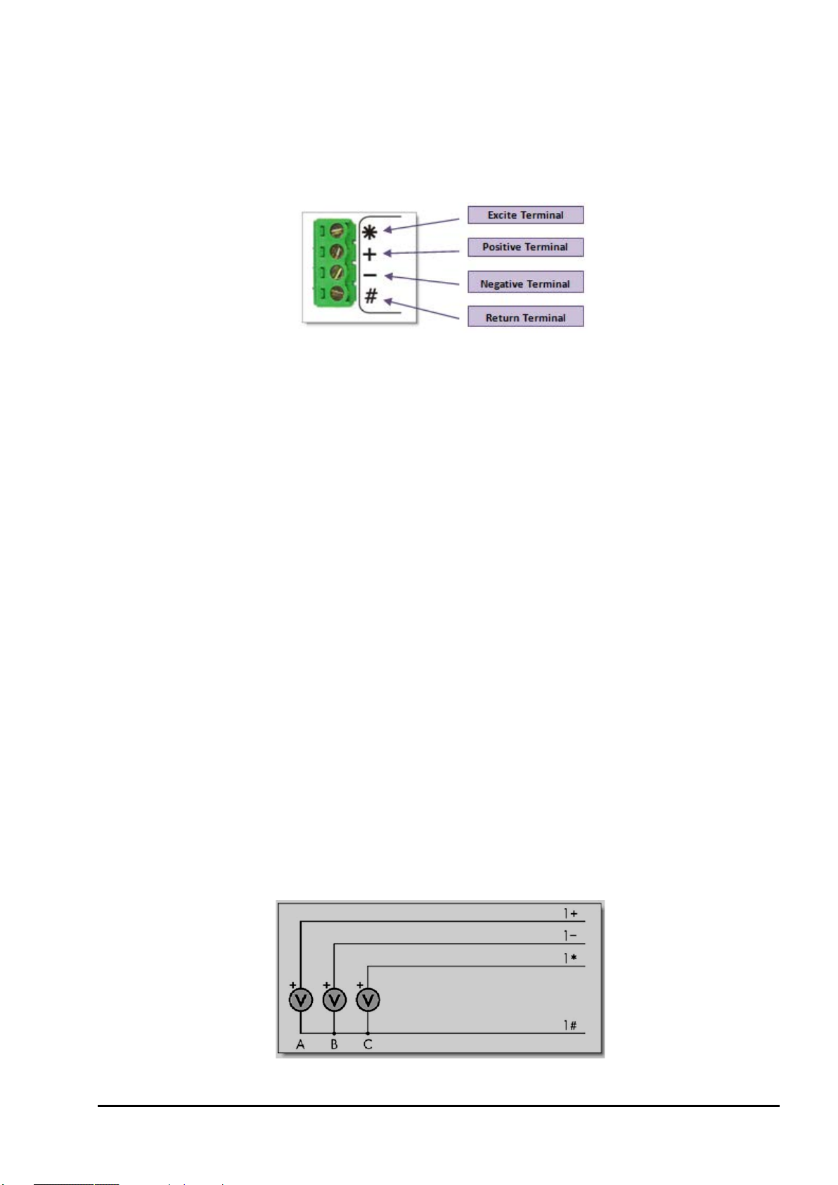
The exact function of each terminal varies depending on how the channel is programmed. In general terms:
• The * ("Excite") terminal can be a voltage input (relative to # terminal), or it can provide sensor excitation (for
example, for resistance measurement) See Sensor Excitation (P24)
• The + ("Plus") terminal is a voltage input (relative to – or # terminal)
• The – ("Minus") terminal is a voltage input (relative to # terminal)
• The # ("Return") terminal is normally used as a common or return terminal. It can also be used as a current
input, using the DT80's internal shunt resistor.
Figure 3: Analog input channel terminal labels
Multiplexers
The DT80's analog input channels are multiplexed. The required input terminals are first connected to the input of the
DT80's instrumentation amplifier and analog to digital converter, then a measurement is taken. The next channel to be
sampled is then switched through to the amplifier and ADC, and so on. Simultaneous sampling of analog channels is not
possible.
Channel definition commands in the DT80 program determine which terminals are used for a particular measurement.
For example, the channel definition
1+V measures the voltage between the + and # terminals on channel 1.
Gain Ranges and Attenuators
The DT80's instrumentation amplifier has three switchable gain settings. These give three basic voltage measurement
ranges (3V, 300mV and 30mV full scale)
The DT80’s default is for its instrumentation amplifier to automatically change gain range to suit the input signal applied
to it by the multiplexers.
If the amplitude of your input signals are known, then the gain can be set manually. Do this by applying the
GLx (gain
lock) channel option, which disables autoranging for that channel and sets the gain to a fixed range.
The analog inputs also include switchable 16:1 (10:1 for Series 3 or older) attenuators, which effectively provide a fourth
range.
Warning: Maximum input voltage on any analog input is ±50V dc (±30V for Series 3 or older), relative to the AGND/EXT# terminal. If
this is exceeded then permanent damage may occur.
Analog Input Configurations
The basic quantity that the DT80 measures is voltage. Voltages can be measured using two different input
configurations:
• shared-terminal analog inputs
• independent analog inputs
Shared-Terminal Analog Inputs
Sometimes called "single-ended" inputs, a shared-terminal input is one that shares one or more of its terminals with
another input. In Figure 4, the three sensors share channel 1’s # terminal. Each of the three inputs is a shared-terminal
input.
Figure 4: Shared-terminal voltage inputs sharing a channel’s # terminal (voltage inputs used as example)
UM-0085-B09 DT80 Range User Manual Page 23
RG
Page 24
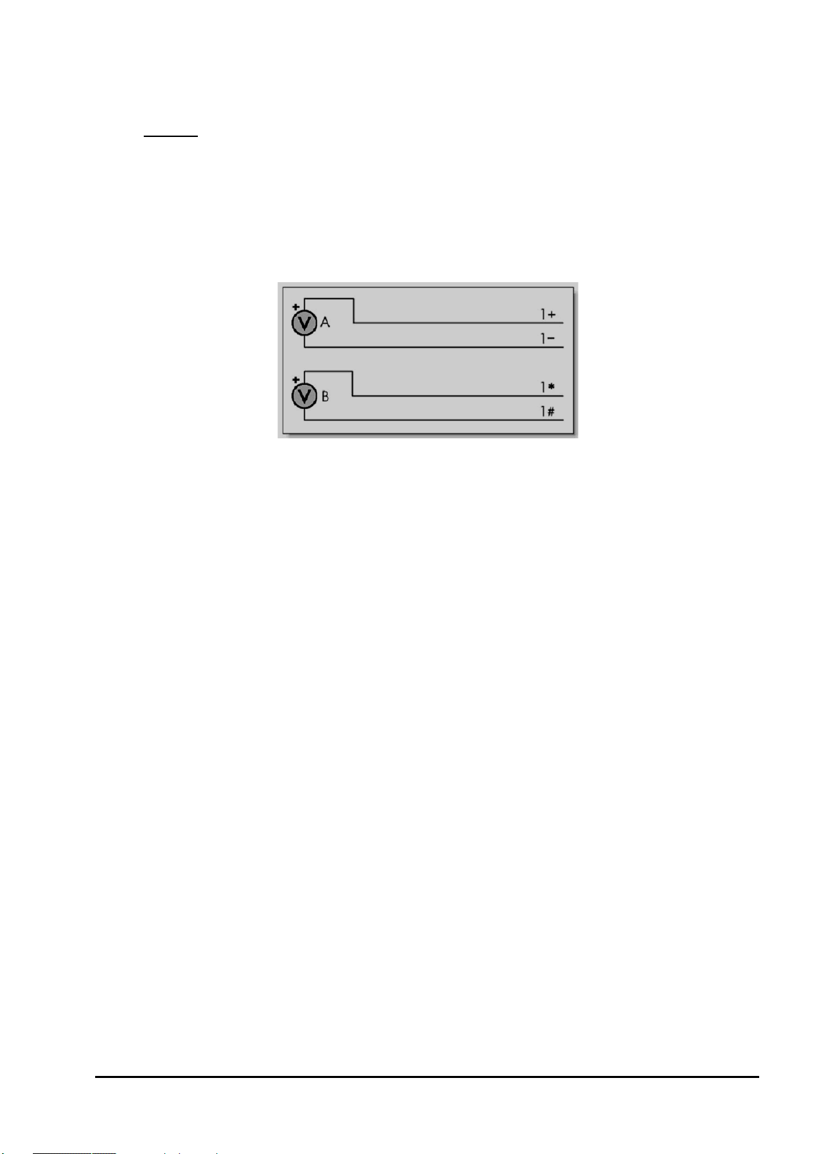
In a shared-terminal configuration, a sensor’s "return" or "negative" wire is usually connected to the channel's # terminal.
The remaining sensor wire (the "positive" or "signal") is connected to any of the channel’s other three terminals. The
common terminal need not be at ground potential – all voltage measurements (shared or unshared) are differential, i.e.
only the difference
For shared-terminal inputs, the channel number is given a suffix indicating the terminal to which the positive wire is
connected. For example, a shared-terminal voltage input applied to channel 1 between the + and # terminals is
recognized by the channel definition
Independent Analog Inputs
An independent input (also known as an "unshared" input) is one that connects to its own terminals and does not share
any of those terminals with any other inputs. For example, in Figure 5, sensor A is connected to channel 1’s + and –
terminals, and sensor B is connected to the other two terminals of the channel. In other words, each sensor’s terminals
are independent of the other’s — no terminal is used by both sensors.
in voltage between the two terminals is reported.
1+V.
Figure 5: Wiring one or two independent inputs to a single channel (voltage inputs used as example)
Note: each analog input channel can support two independent voltage inputs. In the above example, the channel definition
sensor A while
1*V will read sensor B. The channel definition syntax is fully described in Channels (P33).
1V will read
Sensor Excitation
Many sensors require excitation (electrical energy) so that they can provide an output signal. For example, to read the
temperature of a thermistor, excitation current is passed through the thermistor to generate a voltage drop that can be
measured.
The DT80 can provide:
• Voltage source of approx. 4.5V via 1kΩ. Useful for powering some sensors however the supply is not regulated
and consequently liable to drift with temperature
• 2μA (approx.) current source. Excitation for high resistance measurement. Very stable over environmental
temperature range.
• 200μA (approx.) current source. Default excitation for resistance measurement. Very stable over environmental
temperature range.
• 2.5mA (approx.) current source. Default excitation for RTD and bridge measurement. Very stable over
environmental temperature range.
• DT 80 Series 4 provide 16-bit resolution Voltage/Current digital-to-analog converter outputs at V/I DAC terminal.
The current outputs can be set within 0-24mA range and voltage is within 10mV-10V range. The DAC output
can also be used as an external voltage or current excitation for many sensors. It can also be externally routed
to EXT* terminal.
• User supplied external excitation EXT* terminal. The user can provide an external excitation which is
appropriate to the sensor being used. See the Excitation category in the DT80 Channel Options (Table 5: DT80
Channel Options – P47).
More Information
For full details on how to connect sensors and make measurements using the DT80's analog inputs, see Analog
Channels (P302).
UM-0085-B09 DT80 Range User Manual Page 24
RG
Page 25

Digital Channels – Introduction
Figure 6: DT80 digital terminals
The DT80 provides:
• 4 bidirectional digital I/O channels (1D-4D) with open drain output driver and pull-up resistor (DT81/ 82E: 3
channels, 1D-3D)
• 4 bidirectional digital I/O channels (5D-8D) with tri-stateable output driver and weak pull-down resistor. These
channels may also be used for controlling intelligent sensors using the SDI-12 protocol (DT81/ 82E: 1 channel,
4D)
• 1 voltage free latching relay contact output (RELAY)
• 1 LED output (Attn)
• 4 hardware counter inputs (1C-4C) which can be used as independent counter channels or as two quadrature
(phase encoder) inputs (DT81: one phase encoder input, shared with inputs 3C and 4C. There are no phase
encoder inputs on the DT82E)
As with analog channels, channel definition commands are used to specify which digital inputs are to be measured
and/or what digital output states are to be set. For example, the command
channel 1D, while
A transition on a digital channel can be used to trigger a schedule. This allows a series of measurements to be made (or
commands executed) in response to a change in digital state.
The DT80 can count the number of pulses received on any digital input. The four dedicated counter inputs provide
additional capabilities:
• a higher maximum count rate
• the ability to keep counting even if the logger is in low-power "sleep" mode
• optional low-level (5mV) input threshold levels
• optional decoding of phase-encoded input signals
For more details, see Digital Channels (P331)
3DSO=0 will set channel 3D low.
1DS will read the digital state (0 or 1) on
Serial Channels – Introduction
The DT80 supports two main classes of "smart sensor":
• A wide range of sensors, particularly in the environmental monitoring field, use the SDI-12 protocol. The DT80
fully supports this protocol making it a simple process to read measured values. See SDI-12 Channel (P362).
• The DT80 also provides a generic serial channel.
The serial channel allows a wide variety of sensors and devices to be controlled and polled. The serial channel:
• can use the dedicated serial sensor port (not DT81/82E), the host RS232 port (not DT8xM), and/or the USB port
• supports USB, RS232, RS422 and RS485 signal levels (depending on the port)
• supports point-to-point or multi-drop operation (point-to-point only for the host/USB port)
• features programmable output (poll) strings and a variety of options for parsing returned data
• can trigger execution of a schedule in response to received data
For more details, see Generic Serial Channel (P348).
UM-0085-B09 DT80 Range User Manual Page 25
RG
Page 26

Programming the DT80
Typical Workflow
When creating a program to send to the DT80, typically the work will follow this order:
Connect Sensors
Sensors & Channels (P302) describes how to measure many different quantities and read many different sensor types
using the DT80’s analog, digital and serial inputs.
The first step is therefore to refer to the sub-section relating to the quantity you wish to measure. This will help you
decide on the most appropriate way to connect the sensor to the DT80.
Define Channels
Programming the DT80 essentially consists of :
• defining a series of measurements to take, and
• specifying when to take them.
Each measurement definition is referred to as a channel. It is important to be clear on how the word “channel” is used –
in DT80 parlance, it refers to a measurement to be made, not a physical input channel.
For example, if you program the DT80 to measure a voltage on analog input 1, then read the state of digital input 3, then
measure the voltage on analog input 1 again then you have defined three channels. The fact that the first and third
channels both measure the same physical quantity (the voltage on analog input 1) is irrelevant – as far as the DT80 is
concerned, they are two entirely separate measurements.
To specify when measurements are to be made, channel definitions may be grouped into schedule definitions. These
specify whether the channels should be sampled immediately, or periodically, or in response to some event.
To define a channel, you need to specify:
• the input number (e.g.
• the channel type (e.g.
• any channel options that may be required (listed in parentheses, e.g.
1 for analog input 1)
V to perform a voltage measurement)
(GL3V,FF3)
So to define the three channels mentioned above, you could enter:
Since we haven’t specified any schedule, these three measurements will be taken immediately, one after the other.
Default settings will be used, since no channel options were specified. By default, the DT80 will then return the measured
values in ASCII form to the host computer, e.g.
So once you have connected the sensor as described in Sensors & Channels (P302), you can then test it out by directly
entering a suitable channel definition.
For example, suppose we want to check the resistance of a resistor. In the section Resistance (P308), several different
wiring configurations are given. In this case we are going to connect the resistor directly to the DT80’s terminals so we
don’t need to worry about lead resistance issues. The simplest 2-wire configuration is therefore suitable, as described in
R4 – 2-Wire Independent Resistance Inp uts (P310). We therefore pick an analog input to use, say input 2, and wire the
resistor between the * and # terminals on analog input 2. We can now enter the channel definition:
DT80>
2*R 559.1 Ohm
In this case the channel number is
(measure resistance) and there were no channel options, so the complete channel definition is
Note: a particular physical input can be read using different channel types.
For example, a thermocouple can be read as a thermocouple or as a voltage. The command
returns both a temperature and a voltage based on two readings of the same sensor.
For more information about how channels (measurements) are specified in the DT80 programming language, see
Channels (P33).
1V 3DS 1V
1V 234.9 mV
3DS 1 State
1V 233.0 mV
2*R
2* (analog input 2, measuring between * and # terminals) and the channel type is R
2*R.
1TK 1V
UM-0085-B09 DT80 Range User Manual Page 26
RG
Page 27

Define Measurement Schedules
A schedule defines when a set of channels should be measured. It consists of a list of channel definitions preceded by a
scan trigger specification. See Schedules (P48).
As a general rule when creating schedules, don’t instruct the DT80 to read channels more frequently than is really
necessary. For example, temperatures generally change slowly so rapid reading does not provide extra useful
information.
Up to eleven different schedules can be declared (A to K), each with a different trigger based on a time interval or a
digital input event. The schedule’s trigger can be changed at any time, either manually or under program control.
A list of channels without a trigger specification can be entered at any time. These are scanned immediately, without
affecting other schedules that may be operating. For more information, see Immediate Report Schedules (P56).
Important Whilst a schedule’s trigger can be changed at any time, its channel list cannot be altered without re-entering
all schedules. In fact, all schedules must be entered at the same time, either all on one line or between BEGIN and END
keywords (see Working with Schedules (P58)).
Jobs
A DT80 job is a logical "hold-all" for a group of schedule definitions and other commands. The command BEGIN signifies
the start of a job, and the command END signifies the end of the job. Once a job has been fully entered, the DT80 will
activate all schedules defined therein.
The DT80 can store more than one job (each with its own separate logged data and alarms), but only one can be the
current/active job. See Jobs (P61) for more details.
Scaling and Calculations
The DT80 can scale the channel input data to engineering units by applying intrinsic functions, spans or polynomials.
Arithmetic expressions provide cross-channel and other calculations. Various statistical functions, including averaging
and histogram channel options, can be applied. See Scaling (P65).
Reducing Data
In many instances the volume of the data recorded can be reduced by taking averages, maximums, minimums, standard
deviations, histograms or integrals. See Statistical Channel Options (P76).
Alarms and Conditional Execution
The DT80’s alarm facility is flexible and powerful. Alarms are used to warn of certain conditions (e.g. setpoint exceeded)
and to control the DT80’s operation. Alarms can
• control DT80 digital state outputs
• initiate execution of DT80 commands
• trigger the sending of messages to the host computer.
• set variables
Executing DT80 commands from an alarm can be particularly useful in modifying the DT80’s programming in response to
changes in input(s). See Alarms (P82).
Data Logging
The DT80 stores measurements in its internal data store or in a removable USB memory device. Logging begins only
after you issue the
By default, the DT80 overwrites the oldest data with new data once the memory is full. If you prefer to have the logger
stop logging once the memory is full then you need to set the no-overwrite schedule option
For more details see Logging and Retrievi ng Data (P94).
Selective Logging
To selectively log channels and schedules:
• For channels, use the
• For schedules, use the
LOGON command. Time and date stamping is automatic.
(NOV)(P49).
NL (no log) channel option
LOGONx & LOGOFFx commands
See Enabling and Disabling Data Logging (P94).
UM-0085-B09 DT80 Range User Manual Page 27
RG
Page 28

Retrieving Data
The DT80 can do two things with the data it measures:
• Return it immediately to the host computer, where it can be seen arriving on-screen. This monitoring function is
data return in real time.
• Store it in its internal memory and/or an inserted USB memory device ready for retrieval (unload) to the host
computer at a later time. This is data logging.
The DT80 can carry out these functions separately, or at the same time.
Retrieving Real-Time Data
The DT80’s default is to return data in ASCII text form to a connected host computer instantaneously – that is, as it is
measured. (To override this send the /r switch to the data logger (P262)).
The logger's inbuilt dEX software can also display real-time data in tabular form in your web browser, or you can define
mimics to display the data in graphical form such as dials or trend charts.
Note: if the DT80 is configured to take measurements at a rapid rate then it is possible that not all data values will be returned. All
measurements will, however, be logged (if logging is enabled).
Retrieving Logged Data
Data stored in a DT80’s internal memory or USB memory device can be retrieved (or unloaded) by means of the Host
RS 232 port, the Ethernet port, or the USB port. Data can be retrieved for an individual schedule or all schedules, or for
all jobs or an individual job.
USB memory devices
The DT80’s USB port supports USB memory devices, which can be used
• as a medium for transferring logged data from the internal memory of a DT80 to a computer (see Retrieving
Logged Data (P98))
• as removable data storage. See Logging Data (P94)
• to load a job into a DT80. See ONINSERT Job (P64)
• to upgrade a DT80’s firmware. See Firmware Upgrade – USB Flash Device (P395)
Data stored on the USB memory device is in a Windows-compatible file structure – see
UM-0085-B09 DT80 Range User Manual Page 28
RG
Page 29

The DT80 File System (P114).
UM-0085-B09 DT80 Range User Manual Page 29
RG
Page 30

Format of Returned Data
As mentioned earlier, the DT80 can:
• make data available to a host computer as it is measured (real-time data), and/or
• store data in memory to be retrieved at a later date (logged data)
You can control whether data is returned or logged on a per channel, per schedule or global basis.
Real-time data
Web Access (dEX)
If the DT80 is connected to a host computer via a TCP/IP network then the logger's built in web interface can be used to
display real-time data in any web browser. This may be presented in tabular numeric format, or as graphical "mimic"
displays. See Displaying Real -Time Measurements (P150).
ASCII Data
The DT80 can also return real-time data in ASCII (text) form via its command interface. This can be in one of two
formats:
• free format mode
• fixed format mode (also known as "host mode", or "formatted mode")
/h switch command selects free format mode (which is the default); /H selects fixed format mode.
The
Free Format Mode /h
In free format mode, data is returned as human-readable ASCII text. Various settings are available to control how the
data is presented. By default, each channel is printed on a separate line, prefixed by its name (either a standard DT80
channel name e.g. "
3TK", or a user-specified name e.g. "Inlet temp") and followed by appropriate units.
Thus the following program:
would result in text similar to the following text being sent to the active communications port:
Pressure 102.3 kPa
2TK 98.0 degC
Valve state 1 State
Pressure 107.3 kPa
2TK 98.2 degC
Valve state 1 State
and so on.
By applying various formatting settings you can get different results. One possible example would be:
which would format the data thus:
12:46:00.029 102.32 97.98 1
12:46:30.017 107.34 98.22 1
In this example,
channel names and units. The
parameter setting (P260) that sets each data value to a fixed width (10 characters). Finally, the
(P47) specifies that the channel value is to be rounded to 2 decimal places.
RA30S 1V("Pressure~kPa") 2TK 5DS("Valve state")
/n/c/u/T P33=10 RA30S 1V("Pressure~kPa",FF2) 2TK(FF2) 5DS("Valve state")
/n/c/u are switch commands (P262) that have been used to switch off output of channel numbers,
/T switch causes each data record to be prefixed by a timestamp. P33=10 is a
FF2 channel option
Fixed Format Mode /H
Fixed format mode is designed for use with dataTaker host software. Data is still returned in ASCII form, but the record
format is fixed to allow it to be easily parsed by a computer. If /H is specified then both of the above examples will return
data as:
D,081044,"JOB1",2005/03/29,12:46:00,0.0293681,0;A,0,102.322,97.979902,1;0072;065F
D,081044,"JOB1",2005/03/29,12:46:30,0.0170320,0;A,0,107.341,98.220014,1;0072;3BEB
UM-0085-B09 DT80 Range User Manual Page 30
RG
Page 31

In fixed format mode:
• all formatting commands (e.g. FF2, /n, channel names) are ignored – fixed settings are used
• all records are prefixed by a header, which specifies that this is a data record (D), from DT80 serial number
081044, running a job called "JOB1". This is followed a timestamp (date, time, and sub-second time). The 0
indicates that this is real-time data, the A identifies the schedule, and the 0 is the indEX within the schedule of
the first data value.
• floating point data values are always specified to 8 significant digits
• each record includes an error-detection code (CRC) on the end. This allows host software to reject corrupted
records.
Data records such as the above are only one of several types of fixed format message. A comprehensive description of
all fixed format message types is beyond the scope of this manual.
Logged Data
This section discusses the different formats in which logged data can be retrieved. For details on how to go about
retrieving your data, what mechanisms are available (web, file, FTP etc.) and what commands and options to use, see
Retrieving Logged Data (P98).
CSV Format Data
CSV (comma separated value) is a widely used text based format for transferring data. The DT80 command COPYD can
be used to report logged data in CSV format. Data can be written to either:
• the active comms port, so the data appears in the dEX or DeTransfer command window from which the
COPYD command was issued, or
• a file on the DT80's internal file system, or
• a file on a removable USB device, or
• a file on an FTP server
CSV Record Format
By default, the DT80 merges logged data and alarms from multiple schedules into a single file. The file consists of a
number of rows. Each row is terminated by a CR-LF sequence. Each row consists of a number of fields (columns),
separated by commas.
Each row consists of the following fields, in order:
• timestamp (e.g. 2010/03/01 09:54:38.000)
• timezone. Currently, this field will always have the value "n", meaning "no timezone"
• data values for first schedule (zero or more fields, one for each loggable channel). Numeric data values are
specified in "mixed" format (may be either standard or exponential format), to 8 significant digits and trailing
zeroes after the decimal point are trimmed. String values are enclosed in quotes, with any control characters
represented in ^c form (e.g. a CR character would appear as ^M).
• alarm number, alarm state (0-3) and alarm text (see Alarm Records (P91)) for first schedule (three fields; only
present if schedule has one or more loggable alarm channels)
• data values for second schedule (if any)
• alarm number, alarm state and alarm text for second schedule (if any)
• (and so on, for each schedule)
The first row in the file is a header row, which contains a descriptive name for each field. For example, the name of a
data value field has the form "chanName (units)", e.g. "Ext Temp (degC)"
The first block of rows after the header row contain all data records for the first schedule. The next block of rows contain
all alarm records for the first schedule. Then comes the data records for the second schedule, and so on. In other words,
the CSV data is generated in schedule order, not in time order. However, once it is loaded into a spreadsheet it is a trivial
exercise to re-sort by the timestamp field.
Example
For example, a typical file might look like:
"Timestamp","TZ","Ext Temp (degC)","2V (mV)","1CV","B.ALnum","B.ALstate","B.ALtext"
2010/03/01 09:54:38.000,n,22.896844,-0.05822
2010/03/01 09:54:39.000,n,22.894454,-0.058563
2010/03/01 09:54:40.000,n,22.899576,-0.057869
2010/03/01 09:54:41.000,n,22.897856,-0.056656
2010/03/01 09:54:42.000,n,22.893504,-0.05735
2010/03/01 09:54:38.233,n,,,3
2010/03/01 09:54:40.249,n,,,4
2010/03/01 09:54:42.237,n,,,1
2010/03/01 09:54:40.249,n,,,,2,1,"trig 22.9"
UM-0085-B09 DT80 Range User Manual Page 31
RG
Page 32

Variations
To simplify parsing by host applications, the CSV format files generated by the DT80 are essentially fixed format.
However the following parameters may be used to vary the format:
• P38 can be used to change the character used as the decimal point. By default, this is set to 46, which is the
ASCII code for a period character (.). For European applications, it is often set to 44, which is the code for
comma (,). If this is set to comma then the data separator is automatically changed to semi-colon (;).
• P41 can be used to change the number of decimal places shown for timestamp values (default 3).
For example, setting
would result in:
"Timestamp";"TZ";"Ext Temp (degC)";"2V (mV)";"1CV";"B.ALnum";"B.ALstate";"B.ALtext"
2010/03/01 09:54:38;n;22,896844;-0,05822
2010/03/01 09:54:39;n;22,894454;-0,058563
2010/03/01 09:54:40;n;22,899576;-0,057869
2010/03/01 09:54:41;n;22,897856;-0,056656
2010/03/01 09:54:42;n;22,893504;-0,05735
2010/03/01 09:54:38;n;;;3
2010/03/01 09:54:40;n;;;4
2010/03/01 09:54:42;n;;;1
2010/03/01 09:54:40;n;;;;2;1;"trig 22.9"
Data in this format can then be readily imported into spreadsheet applications which are set up for a European locale.
P38=44 P41=0
Error Values
In the event of an erroneous sample value, e.g. analog input overrange, or calculation error, a textual error string will be
inserted into the CSV data in place of the data value, e.g.
2010/03/01 09:54:40.000,n,OverRange,-0.057869
When this is imported into a spreadsheet application, the non-numeric data value will typically plot as zero.
Native (DBD) Format Data
When the DT80 logs data to its internal memory, it stores it in fixed size data files, one for each schedule. These files
have a .DBD file extension, e.g.
An alternative way of getting data out of a DT80 is to transfer relevant .DBD files to the host computer. These files can
then be opened using tools such as:
• dataTaker dump_dbd (which can convert to CSV format). This utility is available on the dataTaker resource CD
or on the datataker.com website.
• third party packages such as DPlot, which provides plotting facilities.
For large data files, it is often significantly faster to transfer data in DBD format, as the DT80 does not need to perform
any data conversion and formatting.
Native format DT80 data files can be saved to files on the DT80 internal file system, a USB memory device or an FTP
server. As with CSV format output, this is done using the
DATA_A.DBD.
COPYD command; the only difference being that a
format=dbd option is specified.
For more details, see Retrieving Logged Data (P98).
Fixed Format Data
Logged data may also be unloaded to a file as fixed format records, as described in Fixed Format Mode /H (P30). This is
primarily intended for use with legacy host applications such as DeLogger.
To retrieve data in fixed format, use
COPYD format=fixed.
Free Format Data
Data may also be unloaded in traditional dataTaker "free format" mode, as described in Free Format Mode /h (P30). This
format may be customised using a number of parameter and switch settings.
To retrieve data in fixed format, use
COPYD format=free.
UM-0085-B09 DT80 Range User Manual Page 32
RG
Page 33

Channel class
Terminal labels
Channel numbers
Applicable channel types
1 – 16
(n = CEM20 number)
* + – #
modifier
1D – 8D
1 – 8
C DB DBO DN DNO DS DSO
counter
1C – 7C
1 – 7
HSC
RELAY
1
RELAY
LED
Attn
1
WARN
Part B – Channels
Channel Definitions
A channel definition defines a measurement to be taken. It is therefore the fundamental building block that you use
when programming the DT80.
Channel definitions are normally enclosed in a schedule definition. The schedule definition specifies when to take the
measurements. The channel definitions specify what
data value.
A sample schedule definition is shown below
RA2S 2DS 3R(4W) 2*V(0.1,GL3V,"Speed~km/h",FF0) 9CV(W)=9CV+1
This shows four channel definitions which are part of the "A" schedule. Each time this schedule runs (which will be every
2 seconds), four measurements will be taken:
1. The logic state of digital channel 2 will be sampled
2. A resistance connected to analog channel 3 (4-wire connection) will be measured
3. A voltage connected to analog channel 2 (* and # terminals) will be measured and displayed as a speed value
4. An internal general purpose variable will be updated (incremented)
Let us now examine the syntax of a channel definition more closely.
A channel definition consists of up to four components
• the channel type is a mnemonic code which tells the DT80 what sort of quantity is being measured, or what
sort of sensor is attached. In the above example the channel types are DS (digital state), R (resistance), V
(voltage) and
• a channel number prefix is required for most channel types. This specifies which channel to measure. In the
above example we are measuring digital channel
9
#
• channel options are enclosed in round brackets after the channel type and further specify how the channel is
to be measured and processed. In the above example, the
options, the
• some channel types are "writable" (e.g. internal variables and digital output channels) and therefore allow a
value to be assigned using an expression. In the above example the 9CV channel definition contains an
expression.
CV (channel variable). A channel definition must always include a channel type.
2DS channel does not.
to measure, on which terminals and how to sample and process the
2, analog channel 3, analog channel 2* and internal variable
3R, 2*V and 9CV channels have user-specified
Channel Numbers
A DT80 channel number identifies a particular channel within a certain class of channels. The following table lists the
various classes of DT80 channels. As can be seen, each class has its own range of channel numbers.
analog
digital
phase encoder
relay
serial
UM-0085-B09 DT80 Range User Manual Page 33
RG
1 – 16 (DT8x)
1 – 20 (CEM20)
1PE – 3PE
shared with counter
1 = serial sensor
2 = host RS232
3 = USB
n01 – n20
plus optional
1 – 3
1 – 3
V HV I L R BGI BGV AS F FW Tx AD5xx CU NI
LMx35 LMxx PT3xx TMPxx YSxx
PE
SERIAL MODBUS
Page 34

Channel class
Terminal labels
Channel numbers
Applicable channel types
TCP/IP
4
MODBUS
power output
PWR12V (Series 3, 4 only)
VDAC IDAC
4D (DT81/ 82)
5 – 8
4 (DT81/ 82)
1 – 1000
CV
system variable
internal
1 – 85
SV
string
1 – 50
$
1 – 4
ST
1
D T DELAY CALC &name CMRR IBAT R100 VANA
VZERO
Modifier
Measure voltage between
+
-
*
* and #
+
+
–
- and #
#
# and AGND/EXT# (normally only used for current measurements)
Sequence
is equivalent to
1..4V
1V 2V 3V 4V
1#..3#I
1#I 2#I 3#I
1+..3-R(3W)
1+R(3W) 1-R(3W) 2+R(3W) 2-R(3W) 3+R(3W) 3-R(3W)
SDI-12
12V
5V SW
12/5V
V/I DAC
5D – 8D (DT80/ 85)
no number
(DT80/ 85)
PWR5V (Series 3 only)
PWR_OUT (Series 4 only)
(Series 4 only)
SDI12
channel variable
timer
temperature
reference
special
internal
internal
internal
internal
internal
no number (DT8x)
– 15 (CEM20)
no number
REFT
VBAT VC VDD VEXT VLITH VREF VRELAY VSYS
The "applicable channel types" column lists the different ways in which a physical input can be measured. For example,
analog channel 1 can be used to measure a voltage (specified by entering 1V), or a PT385 RTD (1PT385) or a
frequency (
1F). All of these channel types fall into the analog class, so when we talk about channel 1 we are talking
about analog channel 1.
Because each channel type is a member of one class only, there is never any confusion about which "channel 1" is being
referred to. 1C refers to digital input 1 because, from the above table, the C (counter) channel type is in the digital class.
1HSC, on the other hand, refers to counter input 1 because the HSC (high speed counter) channel type is in the counter
class. An analog channel number can be suffixed by a modifier character, which identifies the pair of terminals between
which to measure, as shown in the following table:
none
and
and #
Thus the channel ID 3V defines a measurement between the + and – terminals, while 3*V, 3+V and 3-V define
measurements between the *, + or – terminals (respectively) and the # terminal.
Channel Number Sequence
A channel ID that contains two channel numbers separated by two decimal points (for example, 1..3) defines a
continuous sequence of channels. If the channel IDs include terminal modifiers then the sequence will include all terminal
modifiers between that of the first channel ID and that of the second (inclusive, in the order
*, +, –, #, and only where
valid for the channel type). For example:
Channel Types
The following table lists all of the channel types supported by the DT80. For each channel type, the table shows:
• the channel type mnemonic (e.g.
Refer to Channel Numbers (P33) for details of the allowable range of channel numbers for each channel type.
• whether the channel type is "writable" (shown in the Channel Type column). Writable channel types can be
assigned a value, e.g.
2C=200 or 1CV=(2CV+3)+SIN(5CV)
• the default channel options for this channel type. These override the standard default values shown in the
channel option table. See also Channel Options (P41).
• what the channel factor does for this channel type
• the units in which data will be returned. By default, the indicated units string will be shown on the display and
appended to free format returned data, although it can be overridden if required.
• references to further details about the channel type
HV). Remember that in most cases this will be prefixed by a channel number.
UM-0085-B09 DT80 Range User Manual Page 34
RG
Page 35

Category
(100,T)
(100)
(30,T)
TB, TC, TD,
,
,
TS, TT
PT385
PT392
degC
Note 3
degC
Note 3
degC
YS01
YS17
AD590
TMP17
Semiconductor current source
LM135
LM335
LM34
TMP37
T
writable
D
Voltage
Current
Resistance
Bridge
Frequency
Channel
Type
V
HV
I
L
R
BGI
BGV
F
FW
Signal\ Sensor Details
Voltage
input ranges are ±3V,
±300mV & ±30mV
Higher Voltage
input ranges are ±50V (±30V
Series3 or older)
±3V & ±300mV
Current
4-20mA current loop
Resistance by 2, 3 or 4-wire
methods, 10KΩ, (1MΩ
Series4) maximum.
4-wire bridge, 3-wire
simulated bridge
current excitation
4 & 6-wire bridges, voltage
excitation
Frequency measurement
Vibrating Wire Strain Gauge
frequency
DT80G/85G only
Default Channel
Options
(U)
Note 1
(A)
Note 1, 2
Note 2
(I,3W)
(350,II,3W)
(V,4W)
Note 1
(200,MD350)
Channel
Factor
scaling
factor
scaling
factor
current
shunt Ω
current
shunt Ω
offset adjust
Ω
Note 4
arm
resistance Ω
offset adjust
ppm
Note 4
sample
period ms
sample
period ms
Output
Units
mV
V
mA
%
Ohm
ppm
ppm
Hz
Hz
More Information
Voltage (P303)
Current(P306)
Resistance (P308)
Bridges (P311)
Bridges (P311)
Frequency (P323)
Strain Gauges – Vibrating
Wire (P325)
Temperature
TE, TG, TJ
TK, TN, TR
NI
CU
YS02
YS03
YS04
YS05
YS06
YS07
YS16
AD592
LM235
LM35
LM45
LM50
LM60
TMP35
TMP36
Thermocouples Type B, C, D,
E, G, J, K, N, R, S and T
Platinum RTDs
(α = 0.00385, 0.00392)
Nickel RTD
(α = 0.005001)
Copper RTD
(α = 0.0039)
Thermistors: Yellow Springs
400XX series
types (Analog Devices)
Semiconductor (zener diode)
voltage output types
Semiconductor voltage output
types
(T)
Note 1
(100,3W,II)
(1000,3W,I)
(100,3W,II)
(3W,I)
(100,V,U)
Note 2
(2,V)
(V)
scaling
factor
0°C resistance Ω
0°C resistance Ω
0°C resistance Ω
parallel
resistor Ω
current
shunt Ω
voltage
divider
offset adjust
°C
Note 4
degC
Note 3
Note 3
degC
Note 3
degC
Note 3
degC
Note 3
degC
Note 3
Temperature –
Thermocouples (P315)
Temperature – RTDs
(P319)
Temperature –
Thermistors (P317)
Temperature – AD590
Series IC Sensors (P319)
Temperature – LM135
Series IC Sensors (P322)
Temperature – LM35
Series IC Sensors (P321)
Time, Date
and System
Timers
UM-0085-B09 DT80 Range User Manual Page 35
RG
writable
Time of day
Day or date
Time (P37)
Date (P38)
Page 36

Category
1ST
DELAY
schedule execution for
SV
writable
CALC
(P53)
default timeout
SSPORT
writable
(MBI,MES,TO3,
RT0)
factor
PWR12V
PWR5V
PWR_OUT
VDAC
IDAC
writable
DS
Digital state input (1 bit)
State
Note 5
Note 5
analog channel
(mV)
DSO
writable
DNO
writable
DBO
writable
Note 5
RELAY
writable
0=Relay output open
Note 6
WARN
writable
0=Attn LED off
Note 6
C
HSC
Channel
Type
Signal\ Sensor Details
Default Channel
Options
Channel
Factor
Output
Units
More Information
Time, Date
and System
Timers
Delay
System Data
Variables
Calculation
Reference
Text
Serial
Modbus
2ST
3ST
4ST
writable
writable
some are
CV
writable
IV
writable
&name
$
writable
SERIAL
SDI12
MODBUS
System timers
Increment every
sec (1ST), min (2ST),
hour (3ST), day (4ST)
Delays
nominated time
System variable
Channel variables: general
purpose holders for data,
calculation results
Integer variables
Temporary holder for
calculation result
Last measurement value for
channel called name
General purpose text for
headings, etc. (max. 80
characters each)
Transmit to and receive from
serial device
Control SDI-12 sensors using
digital channels 5-8
Enable/disable serial sensor
port (not DT81)
Read/control Modbus sensors
(60)
(60)
(24)
(7)
ie. P53 specifies
(AD0,R1)
range
scaling
factor
scaling
factor
scaling
factor
scaling
factor
scaling
factor
timeout
(sec)
scaling
factor
delay (ms)
Note 6
scaling
Counts
ms
State
State
System Timers (P39)
Delay (P39)
Note 6
System Variables (P40)
Channel Variables (nCV)
(P67)
Rainflow Cycle Counting
(P79)
Calculation Only Channels
(P69)
Reference Channels (P69)
Text (P38)
Generic Serial
Channel(P348)
SDI-12 Channel (P342)
Serial Interface Power
Control (P357)
Modbus Channel (P361)
Power Output
Digital
Input
Digital Output
writable
writable
writable
writable
DN
DB
AS
Enable/disable 12V power
output (Series 2,3,4)
Enable/disable isolated 5V
power output (Series 3 only)
Enable/disable 12/ 5V 350
mA output (Series 4 only)
VDAC 16-bit analog output
(Series 4 only)
IDAC 16-bit analog
output (Series 4 only)
Digital nybble input (4 bits)
Digital byte input (8 bits)
Digital state input on an
Output on a single digital
channel.
Nybble output on a group of
digital channels
Byte output on a group of
digital channels
1=Relay output closed
(15)
(255)
(2500)
(15)
(255)
delay (ms)
Note 6
delay (ms)
Note 6, 7
delay (ms)
Note 6, 7
bit mask
bit mask
threshold
delay (ms)
Note 6
bit mask
Note 5
bit mask
delay (ms)
State
State
State
mV
mA
Nybble
Byte
State
State
Nybble
Byte
State
Controlling 12V Power
Output (P290)
Controlling 5V Isolated
Power Output(P291)
Controlling 12V/ 5V Power
Output (P290)
Signal Output (P291)
Signal Output (P291)
Digital Inputs (P332)
Analog Logic State Inputs
(P330)
Digital Outputs (P333)
Counter
UM-0085-B09 DT80 Range User Manual Page 36
RG
1=Attn LED on
Pulse count on digital input (0
writable
writable
to range-1)
High Speed Up Counter (0 to
range-1)
delay (ms)
range
range
State
Counts
Counts
Counters – Low Speed
(P337)
Counters – High Speed
(P338)
Page 37

Category
PE
writable
Channel
Type
Signal\ Sensor Details
Default Channel
Options
Channel
Factor
Output
Units
More Information
Counter
REFT
VBAT
VLITH
IBAT
VREF
VZERO
Internal
Maintenance
R100
VANA
VDD
VSYS
VRELAY
VEXT
CMRR
Table 3: DT80 Channel Types
Phase Encoder
Reference temperature of
DT80 or CEM20 terminal
block
Terminal voltage of internal
6V lead acid battery
Internal Lithium memorybackup battery voltage.
Internal main battery current
Analog 2.5V voltage source
reference
Analog zero voltage reference
Internal 100 Ohm Shunt
Internal analog 3.8V rail
voltage
Internal 3.3V rail voltage
Internal system supply rail
voltage
Internal relay supply voltage
Raw voltage onto system
from external supply
Common-mode rejection ratio
at maximum gain
scaling
factor
scaling
factor
scaling
factor
scaling
factor
scaling
factor
scaling
factor
scaling
factor
scaling
factor
scaling
factor
scaling
factor
scaling
factor
scaling
factor
Counts
degC
Note 3
V
V
mA
V
mV
Ohms
mV
mV
mV
mV
V
dB
Phase Encoders (P340)
Temperature –
Thermocouples (P315),
and CEM20 Temperature
Reference (P378)
Battery flat if below 5.6V.
Replace battery if below
2.8V.
Positive if charging,
negative if discharging
Notes
1.
Input termination is on by default (T) for DT80/ 81 Series 1 for non-attenuated measurements between + and terminals
2. If the current shunt value is specified (as the channel factor) then that value is used. Otherwise, if the
measurement uses the DT80's internal shunt on the # terminal (e.g.
calibrated resistance of its shunt. Otherwise, the external shunt is assumed to be 100.0 ohms.
3#I), then the DT80 uses the actual
3. Alternatively, parameter P36 can be set to force all temperatures to be returned in degF, degR or K.
4. Offset corrections are subtracted from the measured value.
5. The bitmask specifies which channels are affected by a multi-bit read or write. Channels where the
corresponding bitmask bit is zero are not affected. For example
low but the state of outputs 3D and 4D will be unchanged.
1DNO(3)=0 will set digital outputs 1D and 2D
6. The delay channel factor can be used in conjunction with the R channel option to generate a fixed width pulse
output.
Note: use delay carefully as it prevents execution of any other schedules, measurements or outputs during the delay.
7. 5Vsw power output will only be active while analog section is powered (Series 3 only) ; use P21=1 if
continuously power output is required.
Internal Channel Types
The DT80 has its own internal channels, which can be read in exactly the same way as the obvious "external" channels.
Use the channel types below.
Time
The DT80’s real-time clock/calendar has a resolution of 0.1ms, based on a 24-hour clock. Time is read in the same way
as any channel, but without a channel number. That is, sending
returns
Time 11:45:10.213
T
UM-0085-B09 DT80 Range User Manual Page 37
RG
Page 38

This channel type is writable, so you can set the time by sending:
P39=
Format
Example
1
s.s (decimal seconds) since midnight
42310.003
2
705.1667
3
h.h (decimal hours) since midnight
11.7528
P31=
Format
Example
0
Day number
DDDDD
86
1
28/03/2002
2
North American
MM/DD/YYYY
03/28/2002
3
2002/03/28
T=12:20:00
Time can be in several formats, selected by parameter P39 as follows:
0 (default)
Hours:minute:seconds.subseconds
P41 controls the number of sub-second digits between 0 and 6; default is 3 digits
m.m (decimal minutes) since midnight
11:45:10.003
If the time is assigned to a channel variable (see Channel Variables (nCV) (P67)) then the CV will contain the number of
seconds since midnight, e.g.
T(=1CV) 1CV
Time 17:40:50.748
1CV 63650.7
You can also set the time using a CV, e.g.
1CV=7200 T=1CV
1CV 7200.0
Time 02:00:00.000
See also Setting the System Time (P269).
Date
The current date can also be returned and set:
D
Date 22/05/2005
Date 25/12/2010
Date can be in several formats, selected by P31 as follows:
D=25/12/2010
(default)
European DD/MM/YYYY
ISO YYYY/MM/DD
If the date is assigned to a channel variable then the CV will contain the number of seconds since 1-Jan-1989. The date
can also be set from a CV, e.g.
D(=1CV) 1CV=1CV+86400 D=1CV
Date 04/03/2010
1CV 668176400.0
Date 05/03/2010
System Variables
The following system variables (see System Variables (P40)) return date related information which can then be tested in
alarms:
• 12SV returns the current date/time as decimal days since 1-Jan-1989
• 15SV returns the day number of the year (0-365)
• 20SV returns the day of the month (1-31)
• 21SV returns the month (1-12)
• 22SV returns the year (1989-9999)
Text
Fifty 80-character text channels (1$ – 50$) are available for labelling, data headings, site identification, DT80
identification, and so on.Define the string by sending, for example
Then, the string is returned (unloaded) whenever n$ is included in a channel list. Text channels can also be set based on
data returned via the serial channel. Control String – Input Actions (P353)
Control characters may be included in the text string, e.g.
2$="my text string^M^J"
^M for carriage return.
UM-0085-B09 DT80 Range User Manual Page 38
RG
Page 39

System Timer
Channel Type
Increments Every
Default range
Provides
1
1ST
1 second
60 (1 minute)
Second of the minute
2
2ST
1 minute
60 (1 hour)
Minute of the hour
3
3ST
1 hour
24 (1 day)
Hour of the day
4
4ST
1 day
7 (1 week)
Day of the week: (0 = Sunday, 1= Monday, etc.)
Internal Maintenance
There are several internal maintenance channels, which are read in the same way as normal channels. These allow, for
example, the terminal voltage of the DT80's internal batteries to be measured. See the Internal Maintenance section of
the DT80 Channel Types table (P37).
System Timers
There are four internal reloading system timers, which are read in the same way as channels. The four timers increment
at the following rates, and reset to zero when their range (maximum value) is reached:
System timers are normally synchronised to the previous midnight or Sunday, and increment at the beginning of each
second, minute, hour or day. If the DT80's date/time is set, the system timer channels will be updated to match the new
time.
The range of a system timer can be set using the channel factor. For example,
resetting every quarter hour, on the quarter hour. If the range is set to 0 then the timer will not reset, except at midnight
(1-3ST) or midnight Sunday (4ST)
If a system timer is explicitly set to a value, e.g. 1ST=12, then it will no longer necessarily be synchronised to the actual
time. In this example, after being set
1ST will count up from 12 to 60, at which point it will reset back to 0 and start
counting again. It will always differ from the time-of-day seconds count by a fixed offset.
If a system timer's range is set, it will automatically be resynchronised to the actual time. Therefore
entered at any time to return
2ST to its default behaviour. If a system timer is set to a value outside its range, it is
immediately adjusted so that it is in range. When you enter nST=x, you are actually doing n
2ST=62 will actually set 2ST to 2.
Examples
Assume the time is now 12:34:56. Then:
2ST
2ST 34 (34 minutes past the hour – counter resets on the hour)
2ST(0)
2ST 754 (754 minutes since midnight – counter resets at midnight only)
2ST(22)
2ST 6 (754 mod 22 – counter resets at midnight and every 22 minutes thereafter)
2ST=1
2ST 1 (counter is no longer synchronised to midnight)
2ST(22)
2ST 6 (setting range value resynchronises timer to current time)
2ST will now increment every minute, resetting back to 0 each time it reaches 22. When midnight comes around, it will
again be reset to 0.
2ST(15) will count from 0 to 14,
2ST(60) can be
ST=x mod range. Thus
Delay
It is often useful to insert a fixed delay into a DT80 program. There are two ways of doing this, each for a particular
purpose.
As discussed in Executing Commands in Schedules (P59), there is a distinction between channel definitions and
commands. Channel definitions (1V, T, 5SDI12 etc) are executed as part of a schedule. Any commands (U, G,
DELDATA etc.) triggered by the schedule (using ALARM or DO statements) will be queued but not executed until the
schedule completes.
The DELAY=n channel definition will insert a delay of n ms between two channel definitions. For example:
RA20S 1WARN=1 DELAY=1000 1WARN=0
will turn on the Attn LED, wait one second, then turn it off. (There are more better and more compact ways to do this, e.g.
1WARN(1000,R)=1; the above is simply to illustrate a point.)
On the other hand, the PAUSE n command will insert a delay of n ms between two commands. The following will do a
similar thing to the previous example:
RA20S DO{SATTN; PAUSE 1000; CATTN}
UM-0085-B09 DT80 Range User Manual Page 39
RG
Page 40

In this case the SATTN and CATTN commands are used to turn the Attn LED on and off, rather than the 1WARN
System
Variable
1SV
Free space in the internal file system (B:)
in kBytes
2SV
3SV
Free space in USB memory device (A:)
in kBytes, 0 if no memory device present
4SV
6SV
Build number of the DT80’s firmware
e.g. = 2 for firmware version 6.18.0002
8SV
Mains frequency setting in Hz (P11)
Can be used to change P11 within a schedule
RA1S 11SV(TR) 1TT
12SV
13SV
14SV
15SV
20SV
Current day of the month
1 - 31
21SV
Current month
1 - 12
22SV
Current year
1989 - 5999
channel
.
Delay Accuracy
The actual delay will not necessarily be exactly as specified. For delays of 20ms or less it will be close (within 1ms). For
longer delays the resolution is +/- 16ms however it is guaranteed that the duration will be at least
the specified time.
For the DELAY channel type, the PT (precise timing) channel option may be specified to force a precise delay time, even
if the duration is greater than 20ms. For example:
Note1: However that during this time all logger operations including communications, display updates and sampling will be suspended.
Note 2: Performing long delays using the
evaluation of other schedules. This is true regardless of whether the
DELAY(PT)=1000
DELAY channel or the PAUSE command is not recommended as it can prevent the timely
PT option is specified.
System Variables
System variables provide various pieces of information about the state of the DT80 and its current job. All system
variables are read-only except where indicated as writable in the table below.
As with any other channel type, SVs are, by default, displayed to one decimal place. Use the
this if required, e.g.
Function Notes Writable
Used space in the internal file system (B:) in kBytes
Used space in USB memory device (A:) in kBytes, 0 if no memory device present
5SV
External power status
14SV(FF2)
0 = external power not connected
1 = external power connected
FFn channel option to vary
7SV
9SV
10SV
11SV
16SV
17SV
18SV
19SV
Job loaded flag
USB memory device presence
ID of the owning schedule
Returns 0.0
Decimal days since base date (00:00, 1-Jan-1989)
DT80 serial number
Version number of the DT80’s firmware e.g. = 6.18 for firmware version 6.18.0002
Day number of the current year (integer) 0 = 1st of January
Host RS-232 port input handshake line states
Host RS-232 port output handshake line states
Serial Channel input handshake line states (RS232 mode
only)
Serial Channel output handshake line states (RS232 mode
only)
0 = no current job
1 = a job is loaded
0 = none
1 = USB memory device inserted
0 = RX schedule
1 = RA schedule
↓
11 = RK schedule
12 = immediate schedule
Can be used as thermocouple reference channel
for cases where the thermocouple output is already
compensated, e.g.
Bitmask, 0 to 15
8 = RI, 4 = DCD, 2 = DSR, 1 = CTS
Bitmask, 0 to 3
2 = DTR, 1 = RTS
Bitmask, 0 to 1
1 = CTS
Bitmask, 0 to 1
1 = RTS
25SV
UM-0085-B09 DT80 Range User Manual Page 40
RG
Status of a modem connected to the DT80’s Host RS-232
port
0 = no modem connected (direct connection assumed)
1 = modem connected and no call in progress
2 = modem connected and call in progress
Page 41

System
Variable
26SV
-1..-5 = last request unsuccessful
27SV
Time discrepancy as at last NTP request
in milliseconds
30SV
Number of logged data records for RX schedule
31SV
Number of logged alarm records for RX schedule
32SV
Number of logged data records for RA schedule
33SV
Number of logged alarm records for RA schedule
↓
52SV
Number of logged data records for RK schedule
53SV
Number of logged alarm records for RK schedule
80SV
Communications session state
see Modem States (P217) (DT8xM models only)
81SV
Result of last communications session
see Communication Errors (P217) (DT8xM models only)
82SV
Last sampled mobile network signal level
value in dBm, typical range -113 to -51 (DT8xM models only)
83SV
Last sampled mobile network type
see Service Type (P220) (DT8xM models only)
84SV
Last sampled mobile network bit error rate
value in % (DT8xM models only)
3 = limited connectivity (link-local IP address)
RA2S 1TK 3R(4W) 2*V(0.1,GL3V,"Speed~km/h",FF0)
29SV
Function Notes Writable
0 = no NTP requests have been attempted
Status of last NTP attempt
Status of last unload attempt
1 = time adjustment in process
2 = last request successful
0 = no unloads have been attempted
1 = unload in progress
2 = last unload was successful
-10..-19 = destination store file error
-20..-29 = source store file error
-30 = communications queue is full
-99 = unload aborted by user
-1 = no current job; or no storefile has been
created for the specified schedule in the current job
0 = disabled/no cable
85SV
Table 4: DT80 System Variables
Current Ethernet communications state
1 = starting
2 = online
Channel Options
Overview
All channel types can be modified in various ways by channel options, which define the way in which the input channel
is managed when sampled. There are channel options that specify the type of sensor excitation, the termination of the
input channel, scaling and linearization of the input signal, the format and destination of channel data, fixed channel gain
values, resistance and bridge wiring methods, statistical operations on the channel data, and so on.
As shown below, channel options are placed in round brackets immediately following the channel ID (channel number
and type). If multiple channel options are specified then they should be separated by a comma (no spaces).
In the above example:
• The first channel, 1TK, has no channel options specified so it will measure the thermocouple using default
settings.
• The second channel (3R) includes the 4W channel option, which specifies that a 4-wire resistance
measurement should be taken.
• Finally, the 2*V channel is in this case used to read a speed sensor which outputs a voltage that is directly
proportional to speed (10mV per km/h). The
channel is interpreted as a simple scaling factor (mV * 0.1 = km/h). The
to select the 3V measurement range (rather than auto-ranging). The last two options concern the presentation
of the data on the LCD display and in returned real-time data when in free format (/h) mode. In particular, they
define the channel name and units, and specify that no decimal places be displayed (
0.1 channel option is the channel factor, which for a voltage
GL3V (gain lock) option tells the DT80
FF0).
The channel's data will therefore be returned/displayed as:
Speed 72 km/h
instead of the default:
2*V 721.3 mV
Only certain channel options can be applied to each channel type. If an inappropriate channel option is applied (or an
incompatible combination of options), the DT80 notifies by returning an E3 - Channel option error message.
UM-0085-B09 DT80 Range User Manual Page 41
RG
Page 42

The same channel can be put in the list more than once, with the same or different channel options. The DT80 treats
Channel Type
Channel Factor’s function
V, HV, T
CALC, &
VBAT, REFT
LMx35 (voltage output)
External voltage divider factor, or slope calibration factor
I, L, AD5
TMP17
Resistance (ohms) of the external current shunt (the DT80 uses this value and the
voltage it measures across the shunt to calculate current flow)
LMxx, TMP3x (voltage output)
Offset adjustment (°C)
BGI
Bridge arm resistance (ohms)
BGV (voltage excited bridge)
Offset adjustment (ppm)
PT3xx, NI, CU (RTD)
Resistance of the RTD element at 0°C (ohms)
YSxx (thermistor)
Value of connected parallel resistance (ohms)
R (resistance)
Offset adjustment (ohms)
AS (state)
Logic threshold value (mV)
F, FW
C, HSC, STx (counter, timer)
Count modulo value (reset after every n counts)
DN, DB, DNO, DBO (digital multiple)
Bitmask (only channels with 1 in bitmask are read/output)
DSO, WARN, RELAY, PWR12V, PWR5V
(digital output)
SERIAL
Timeout (sec)
each occurrence as a separate measurement.
A Special Channel Option — Channel Factor
The DT80’s channel factor channel option is simply a floating point number. This number is interpreted in different ways
depending on the channel type, as indicated by the following table.
x, CV, SV,
MODBUS, SDI12, internal channels e.g.
xx,
(current excited bridge)
(frequency)
name,
(current)
Scaling factor – for example, 1V(5.5) means multiply the reading by 5.5
Sample Period (ms)
Delay time (ms)
For example, the three channel definitions in the schedule command
RA30S 1V(10.1) 4PT385(200.0) 2DSO(100,R)=0
contain channel factor channel options that instruct the DT80 to do the following:
• scale (multiply) the voltage measured on input channel 1 by 10.1
• use 200.0Ω (instead of the default 100.0Ω at 0°C) when calculating the temperature represented by the signal
from the RTD on channel 4
• output a 100ms pulse on digital channel 2.
Multiple Reports
The DT80 samples each channel in the channel list once every scan. However, by adding additional channel option sets
(each set enclosed in round brackets) you can generate additional reports. That is, you can report the same data value in
different ways.
The first channel option set determines how the channel is sampled, and must include all sampling options required for
the channel. These channel options are listed above the configuration line in the Channel Option Table (P47). Second
and subsequent option sets may only contain reporting options (those below the configuration line.
Multiple reports are particularly useful for statistical reports (see Statistical Report Schedules (P57)) in that several
different statistical operations can be performed on the same data set.
For Example:
defines five option sets. The first option set specifies one sampling option (
RA1H 3YS04(II,AV)(MX)(TMX)(MN)(TMN)
II – use 2.5mA excitation) and returns the
average temperature value, calculated over the period (1 hour in this case) since the last report scan. The remaining
option sets will return the maximum reading over the same interval, the time at which it occurred, the minimum and the
time of minimum.
Remember that the first option set can contain options from any part of the channel option table, while subsequent option
sets can only contain options from below the configuration line.
Mutually Exclusive Options
Options grouped by a shaded rectangle in the Mutual Exclusions column of the table below are mutually exclusive. If
more than one channel option from a mutual exclusion group is placed in a channel list, only the last one specified is
recognised.
UM-0085-B09 DT80 Range User Manual Page 42
RG
Page 43

Order of Application
The DT80 applies channel options in a specific order, regardless of the order in which they are specified in a channel
definition. The channel option table below lists the channel options more or less in the order of application.
In general terms, the ordering is as follows:
1. First, the raw value is sampled, taking note of sampling options, i.e. those relating to the physical
measurement process. These include options in the input termination (
resistance/ bridge wiring (
2W, 3W, 4W), gain lock (GL30V, GL3V, GL300MV, GL30MV) and excitation (I, II,
III, V, E, N) categories, along with NSHUNT, 2V, ESn and MDn.
The raw value may then be linearised according to the channel type, e.g. for thermocouples the appropriate
polynomial will be applied to convert millivolts into a temperature value (in the units specified by P36).
The resulting linearised value is then further processed as follows.
2. The channel factor is then applied, if specified. For most channel types this is a simple scaling (multiplier)
value.
3. A user specified scaling option – a span (Sn), polynomial (Yn), thermistor scaling (Tn) or intrinsic function (Fn)
– is then applied.
4. The resulting scaled and linearised value may then be manipulated using a data manipulation option –
difference (DF), time difference (DT), rate of change (RC), reading per time (RS) or integrate (IB).
5. A digital manipulation option for measuring the timing of signal transitions may then be applied (TRR, TRF,
TFR, TFF, TOR or TOF)
6. The data value processed up to this point may then be used as a reference value for other measurements (TR,
BR or TZ)
7. The data value may then be accumulated using one or more statistical options (each one in a separate option
set). Statistical channel options include AV, SD, MX, MN, TMX, TMN, DMX, DMN, IMX, IMN, INT, NUM and H
(histogram).
8. Finally, the resultant value after applying the above options (or values if multiple option sets are used) may be
stored in a channel variable using
disabled using the
and "name~units".
NR, NL, ND and W options, and output formatting can be specified using FFn, FEn and FMn
=CV and op=CV options. Return, logging and/or display of the data may be
T, U) , input attenuator (A, NA),
Default Channel Options
All channel options have default values. The DT80 follows a 3-step procedure to determine what options to apply:
1. Start with the basic set of default options specified in the channel option table.
2. If the channel type specifies any default options then they are applied, overriding any conflicting basic default
options. Default options for each channel type are listed in the channel type table refer Table 3: DT80 Channel
Types (P37)
3. Finally, if an option is explicitly specified in the channel definition then that setting is used, overriding any default
setting. If more than one mutually exclusive option is specified then only the last one is used, e.g.
1V(AV,MX) is interpreted as 1V(MX). (If you want to output both the average and the maximum then use two
separate option sets, i.e.
For example, if you specify:
then you are really specifying:
In this case the basic default options are (U,NA,N,ES0,MD10,FF1). The R channel type specifies (I,3W) as its
default options, so the
1R(4W)
1R(U,NA,N,ES0,MD10,FF1,I,3W,4W)
(I) option (200µA excitation) overrides the (N) option (no excitation). Then the user specifies
(4W) which overrides the R channel type's default wiring option setting (3W).
1V(AV)(MX)).
UM-0085-B09 DT80 Range User Manual Page 43
RG
Page 44

81 Series
U
Enable1 ÷10 (1 ÷16 Series 4)
input attenuators
NA
default
2W
3W default
3-wire measurement
4W
4-wire measurement
excitation on * terminal
N
default
A scale factor or other parameter specific to
in Table 3: DT80 Channel Types(P37))
Used with F channel type to set threshold to
rather than the default of 0V.
Can reduce noise. Total measurement time is
only.
FW
1HSC, 2HSC
1PE
Channel Option Table
Category
Input
Termination
(DT80/
1 only)
Input
Attenuators
Resistance and
Bridge
Gain lock
Channel
Option
T
default
A
(none)
default
GL50V
GL30V
GL3V
GL300MV
GL30MV
I
Function
Excl
Mutual
Terminate +, – inputs with 1MΩ
to AGND terminal
Unterminate +, – inputs
Disable input attenuators
2-wire measurement
Auto-range over 3 gain ranges
Lock channel gain for
±50V input signal range (Series
4 only)
Lock channel gain for
±30V input signal range
Lock channel gain for
±3V input signal range
Lock channel gain for ±300mV
input signal range
Lock channel gain for ±30mV
input signal range
Supply 200µA current excitation
on * terminal
Range of
Option (n)
Valid only if input attenuators are enabled
Valid only if input attenuators are enabled
Valid only if input attenuators are disabled
Comment
Provides input bias current path to ground to
prevent inputs "floating" – particularly when
independent (differential) inputs are used.
Not required on DT80 Series 2 or DT85 as a
ground path is always present.
Attenuators default ON for HV, AS channel
types, OFF for other types.
Specifies the number of wires run between
the DT80 and the resistance or bridge. More
wires generally mean better accuracy.
Selects between 3V, 300mV, 30mV ranges if
input attenuators disabled
Selects between 30V, 3V, 300mV ranges if
input attenuators enabled
Precision current source. Low excitation
current minimises self-heating in resistive
temperature sensors and allows high
resistances to be measured.
Excitation
Channel Factor
Reference Offset
Extra Samples
Measurement
Delay
Low Threshold
II
III
V
E
value
2V
ESn
default = 0
MDn
default = 10
LT
Supply 2.5mA current excitation
on * terminal
Supply 2µA current excitation on
* terminal
Supply approx. 4.5V voltage
Connect external excitation
source (EXT * terminal) to
channel's * terminal
No excitation by DT80 (assumes
externally applied excitation)
Linearise/scale the measured
value
Measure relative to 2.5V rather
than 0V
Perform n additional samples
and average them
After selecting channel, delay for
n ms before starting
measurement
Set low input voltage thresholds
for high speed counters
Voltage source is not regulated
depends on
chan type
0 to 30000
0 to 30000
Precision current source. Higher excitation
current allows more accurate measurement
of low resistances (< 700Ω).
Precision current source. Low excitation
current minimises self-heating in resistive
temperature sensors and allows high
resistances measurements.
Excite terminal (*) may be used as a sharedterminal input channel
channel type (see the channel factor column
+2.5V (suitable for TTL level input signals)
n+1 mains periods. Analog channel types
Specifies the settling time required before a
sensor can be measured. Default is 350ms
for
channel. Analog channel types only.
Valid for
(not DT81) channels.
(DT80/81/85) and
UM-0085-B09 DT80 Range User Manual Page 44
RG
Page 45

Category
HSC, ST
each bit after returning its value.
81 Series
1 only)
DELAY, DSO, WARN
RELAY
delay time even for long delays.
See Spans (Sn) (P65)
See Spans (Sn) (P65)
See Polynomials (Yn) (P66)
n
Function
1
1/x
2
√x 3 Ln(x)
4
Log(x)
5
Absolute(x)
6
X2 7 Gray code to binary conversion (16 bit)
Applies a previously-defined thermistor
Temperature – Thermistors(P317)
Δx
Δt
readings (area under curve)
TRR
Time from rising edge to rising
edge
TRF
Time from rising edge to falling
edge
TFR
Time from falling edge to rising
edge
TFF
Time from falling edge to falling
edge
TOR
Time of rising edge
TOF
Time of falling edge
Any non-thermocouple temperature sensor
this schedule
This zero would be measured at the
in this schedule
BGV
Reset
Channel
Option
R
Function
Excl
Mutual
Reset channel after reading
Range of
Option (n)
Comment
Valid for C,
which are reset to 0 after returning their
current value.
Also valid for digital output channel types
(DSO, DNO, DBO) which invert the state of
and CV channel types,
Internal Shunt
(DT80/
Delay
Scaling
Data
Manipulation
NSHUNT
PT
Sn
SRn
Yn
Fn
Tn
DF
DT
RC
RS
IB
Disconnect internal 100R shunt
between # terminal and AGND
Force precise timing
Apply span n
Apply reversed span n
Apply polynomial n
Apply intrinsic function n.
Apply thermistor scaling
(correction) n
Difference
Time difference
Rate of change
Δx / Δt
Reading / time difference
x / Δt
"Integrate"
( x – Δx / 2 ) Δt
1 to 50
(poly & span
indEX is
shared)
1 to 7
1 to 20
Allows # terminal to be used for shared-input
voltage measurements
Valid for
channel types. Forces a precise (+/- 1ms)
Applies a previously-defined span
Applies a span in reverse
Applies a previously-defined polynomial
scaling equation
See Thermistor Scaling (Tn)(P66) and
Returns the difference (xUnits) between the
latest reading and the previous reading
Time difference (seconds) between the latest
reading and the previous reading
Rate of change (xUnits per second) based on
latest and previous readings and their
respective times
Rate of change (xUnits per second). Useful
when the sensor reading is already a
difference (e.g. resetting counters)
"Integration" with respect to time (xUnits .
seconds) between the latest and the previous
and
Digital
Manipulation
TR
Reference
Channel
TZ
BR
UM-0085-B09 DT80 Range User Manual Page 45
RG
Use this channel's value as
thermocouple reference junction
temperature
Use this channel's value to
correct the DT80's electrical
zero
Use this channel's value as
bridge excitation voltage
Normally used for digital channels.
If used on analog channels then channel
factor is interpreted as a threshold value.
measuring isothermal block temperature.If
already compensated use 11SV(TR) as
reference channel (11SV always returns 0.0).
TR channel temperature is used for all
subsequent thermocouple measurements in
isothermal block. TZ channel zero is used for
all subsequent thermocouple measurements
BR channel voltage used for all subsequent
measurements in this schedule
Page 46

Category
AD"n"
Sensor address (quotes optional
for 0-9)
0-9, A-Z, a-z
Rnnn
Register to read
1 to 999
CM
Configure sensor to measure
continuously
by SDI12 version n.n
10, 11, 12,
13
ADn
AD"ip-addr"
Sensor address (TCPIP)
IP address
Rt:
0:0 to
4:65536
data type: int16, unsigned16,
Enron float32
LE, FE
ME
32-bit word order: standard,
reversed
S, R
TOn
comms timeout (sec)
1 to 255
RTn
max retries
0 to 25
MUIDn
unit id
0 to 255
"
"
Analysis
CONFIGURATION LINE (see Multiple Reports(P42) )
AV
Average of channel readings
MX
Maximum channel reading
MN
Minimum channel reading
reading
(using time in seconds)
CV
CV
Subtract channel reading from
nCV = nCV – reading
Multiply channel variable by
nCV = nCV * reading
Channel
Option
Excl
Mutual
Function
Range of
Option (n)
Comment
SDI-12
Modbus
Serial Channel
Rainflow Cycle
VERnn
rrrrr:b
MBtype
order
commands
RAINFLOW
SD
Only use commands supported
Sensor address (serial) 1 to 247
Register(s) to read or write
int32, float32, Enron int32,
Input and output actions ASCII text See Generic Serial Channel(P348)
See Rainflow Cycle Counting (P79)
Standard deviation of channel
readings
I, U, L, F,
See SDI-12 Channel (P342)
See Modbus Channel(P361)
Statistical
See Statistical
Channel Options
(P76)
Variables
See Channel
Variables (nCV)
(P67)
TMX
TMN
DMX
DMN
IMX
IMN
INT
NUM
Hx:y:m..nCV
=nCV
+=nCV
–=nCV
*=nCV
Time of maximum channel
reading
Time of minimum channel
reading
Date of maximum channel
reading
Date of minimum channel
Instant (time and date) of
maximum
Instant (time and date) of
minimum
Integral for channel
Number of samples in statistical
calculation
Histogram
Assign channel reading to
channel variable.
nCV = reading
Add channel reading to channel
variable.
n
= n
channel variable.
channel reading.
+ reading
x, y ±1e18
m, n 1-1000
1 to 1000
1 to 1000
1 to 1000
1 to 1000
These channel options link the channel to the
statistical sub-schedule RS. The channel is
sampled at times determined by the RS
trigger (which defaults to 1S).
At the report time as determined by the report
schedules, the statistical summary is
reported. If insufficient samples have been
taken before the reporting time, an error is
reported (NotYetSet).
.
Divide data range x to y into discrete buckets
and accumulate in CVs the number of
samples in each bucket
See Histogram (Hx:y:m..nCV) (P78)
Channel variables are like memory registers
in a calculator. They can be assigned directly
(e.g. 1CV=2.5), or assigned a channel
reading at scan time (e.g. 1V(=7CV)).
The contents of a variable can also be read,
modified and then updated. For example
1V(/=7CV) means that the value of 7CV is
divided by the reading on channel 1 and the
result is returned to 7CV.
Note that these actions occur only at report
UM-0085-B09 DT80 Range User Manual Page 46
RG
Page 47

Category
Divide channel variable by
nCV = nCV ÷ reading
time and not during statistical sampling.
=m..nCV
channel only)
the host computer (they may still be logged or
(NR,NL,ND)
FF
default = 1
BGmin:max
Default units
User-specified units
No units
Channel
Option
Excl
Mutual
Function
Range of
Option (n)
Comment
Variables
See Channel
Variables (nCV)
(P67)
/=nCV
(MODBUS
NR
NL
Destination
ND
W
LM
n
Output Data
Format
Fen
FMn
Channel name
and Units
Table 5: DT80 Channel Options
"name"
"name~unit"
"name~"
"~unit"
"~"
channel reading.
Assign values to a range of CVs
No return
No log
No display
Working channel
Log alarm measurement
Fixed-point format
n=decimal places
Exponential format, n=decimal
places
Mixed: FF or FE, n=significant
digits
Show value as a bargraph on the display.
User-specified name
User-specified name
User-specified name
No channel name
User-specified units
No channel name
No units
1 to 1000
0 to 7
0 to 7
0 to 7
ASCII text
Channels tagged with NR are not returned to
displayed).
Channels tagged with NL are not logged
(they may still be returned or displayed).
Channels tagged with ND are not displayed
on the LCD (they may still be returned or
logged).
Same as
Working channels are usually used to hold
intermediate values in calculations.
Log the value being tested in an alarm.
Ignored for non-alarm channels.
Specifies numeric format for display and free
format (/h) real-time data.
For example, FF2 returns 71.46 mV
For example, FE2 returns 7.14e1 mV
FMn uses exponential format if exponent is
less than –4 or greater than n
Allows channel name and/or units to be
overridden for display and free format (/h)
real-time data.
Max 24 characters for user-specified channel
name; 10 characters for units.
UM-0085-B09 DT80 Range User Manual Page 47
RG
Page 48

Schedule ID
Schedule Name
Schedule Options
Schedule Trigger
Channel List
Schedule ID
Schedule Name
Schedule Options
Schedule Trigger
Channel List
Schedule ID
Quantity
RA, RB, RC, RD, RE, RF, RG, RH, RI,
RJ, RK, RX
Each time you enter an immediate schedule it
replaces the previous one, if any.
RS
1 available, but is applied to one or more of the
other report schedules
Part C – Schedules
Schedule Concepts
What are Schedules?
Schedules are the workhorses of the DT80. They are the underlying structures that you use to manage the repetitive
processes of the DT80 such as
• scanning input channels
• evaluating calculations
• processing alarms
• managing output channels
• returning data to a host computer
• logging data
The DT80 supports the following schedules:
• 11 general purpose schedules, A-K, which can be triggered by a variety of different events
• a polled schedule, X, which is normally triggered by a poll command from the host computer (although most of
the other triggers can also be applied to it, making it effectively a 12th general purpose schedule)
• the immediate schedule, which executes once immediately after being entered
• the statistical schedule, which collects and accumulates data to be returned as statistical summaries by the
other schedules.
Schedule Syntax
A typical schedule definition is shown below:
RA"Test1"("B:",DATA:OV:14D)2S 1TK 6R(4W) 7TT
Figure 7: Components of a typical schedule command
A schedule consists of a number of parts. Firstly the Schedule ID, next the schedule options and finally the schedule
trigger. There are no spaces between the different parts
Schedule ID
RA"Test1"("B:",DATA:OV:14D)2S 1TK 6R(4W) 7TT
The Schedule ID consists of the letter R ("Report schedule") followed by a letter identifying the schedule. Each schedule
has a unique identifier; these are summarized in the following table:
Report schedules (P51)
Immediate report schedule (P56) No schedule ID
Statistical sub-schedule (P57)
UM-0085-B09 DT80 Range User Manual Page 48
RG
12 available
Page 49

Schedule Name
Schedule ID
Schedule Name
Schedule Options
Schedule Trigger
Channel List
Schedule ID
Schedule Name
Schedule Options
Schedule Trigger
Channel List
Item
Possible Values
Explanation
OV
Data for this schedule will be overwritten when the data store is full (default)
nB
nKB
Allocate n kilobytes for storing data for this schedule
nMB
Allocate n megabytes for storing data for this schedule
nR
nS Note 1
Allocate space for n seconds worth of data for this schedule
nM
nH Note 1
Allocate space for n hours worth of data for this schedule
nD
Allocate space for n days worth of data for this schedule
OV
Alarms for this schedule will be overwritten when the store is full (default)
nB
Allocate n bytes for storing alarms for this schedule
nKB
Allocate n kilobytes for storing alarms for this schedule
nMB
Allocate n megabytes for storing alarms for this schedule
nR
AlarmWidth
Wn
Allocate n bytes for storing each alarm string (default=60 bytes)
RA"Test1"("B:",DATA:OV:14D)2S 1TK 6R(4W) 7TT
The schedule name is optional, and consists of text (max 20 characters) enclosed in double quotes. This name is used in
reports and is normally used to document the purpose of a given schedule.
Schedule Options
RA"Test1"("B:",DATA:OV:14D)2S 1TK 6R(4W) 7TT
Schedule options are enclosed in brackets. They define:
• where to log the data and alarms generated by the schedule (i.e. internal file system or removable USB device)
• the amount of space to allocate for storing data records, and whether old records are to be overwritten when it
is full
• the amount of space to allocate for storing alarm records, and whether old records are to be overwritten when it
is full
For more details on how data logging works, see Logging Data (P94)
The schedule option syntax is as follows:
(Dest,DATA:DataOverwrite:DataSize,ALARMS:AlarmOverwrite:AlarmSize:AlarmWidth)
Dest
DataOverwrite
DataSize
AlarmOverwrite
AlarmSize
"A:"
"B:"
NOV
Note 1
Note 1
NOV
Logged data and alarm information from this schedule will be written
directly to the USB memory device (not recommended, see Logging
Options (P96))
Logged data and alarm information from this schedule will be stored on the
internal flash disk (default)
Data will not be overwritten when the data store is full. When the data store
fills logging will stop and the Attn LED will flash
Allocate n bytes for storing data for this schedule
Allocate space for n data records for this schedule
Allocate space for n minutes worth of data for this schedule
Alarms will NOT be overwritten when the store is full. When the store fills
logging will stop and the ‘Attn’ LED will flash
Allocate space for n alarm records for this schedule
Note: These are only valid for time-triggered schedules (not for polled or event triggered schedules). Furthermore, if the schedule rate is
changed after the job has started running then the store file may no longer contain data for the indicated time span.
UM-0085-B09 DT80 Range User Manual Page 49
RG
Page 50

Schedule ID
Schedule Name
Schedule Options
Schedule Trigger
Channel List
Schedule ID
Schedule Name
Schedule Options
Schedule Trigger
Channel List
Default Schedule Options
All schedule options are optional. Default settings are:
• Destination is B: (internal flash drive)
• New data and alarms overwrite earlier data/alarms once the store file fills
• Space allocated for data is 1MB
• Space allocated for alarms is 100KB
• Space allocated for each logged alarm text string is 60 bytes.
Examples
RA"Fred"(DATA:NOV:15D)15M
Schedule A is given the name "Fred". Data and alarms are stored on the internal drive and sufficient space is allocated
for 1440 readings (15 days worth, based on a 15 minute scan rate). In this case earlier data is considered more valuable
than later data, so no-overwrite mode is selected. If any alarms are defined in this schedule they will use the default
storage parameters (100KB, overwrite enabled).
Schedule Trigger
RA"Test1"("B:",DATA:OV:14D)2S 1TK 6R(4W) 7TT
All schedules have a trigger, which defines when the schedule is to execute the processes assigned to it. Here are the
DT80’s schedule triggers:
• an interval of time, see Trigger on Time Interval (P52)
• a time of day, see Trigger at Date/Time (P52)
• an external event (such as a digital input transition), see Trigger on External Event (P53)
• an internal event (such as a CV changing), see Trigger on Internal Event (P54)
• a poll command, see Trigger on Poll Command (P54)
Triggers can also be conditional upon an external or internal state (that is, trigger only while a particular external state or
internal state exists) — see Trigg er While (P55).
Channel List
RA"Test1"("B:",DATA:OV:14D)2S 1TK 6R(4W) 7TT
Most often schedules will be created that instruct the DT80 to carry out channel-related tasks, such as scanning one or
more of its input channels and/or setting one or more of its output channels. When these schedules are created, group
the channel details (their IDs and optional instructions) together in a channel list within the schedule. Figure 7 (P48)
shows a typical schedule — notice its schedule header and channel list components.
A channel list may contain just one channel entry or many, and each channel in the list must be separated from the next
by one or more space characters. Similarly, a schedule’s header must be separated from its channel list by one or more
space characters.
The DT80 processes the channels in a channel list from left to right.
UM-0085-B09 DT80 Range User Manual Page 50
RG
Page 51

Example — Channel List
The channel list
specifies the following channels (each is separated from the next by a space character):
Note: the example above is only a channel list and not a complete schedule. Here’s the same channel list used in a schedule (the
schedule header RJ2M has been added):
RJ2M 1V 3R 5..7DS 4TK("Boiler Temp") 3DSO=0
The header identifies the schedule as Report schedule J that runs every 2 Minutes.
1V 3R 5..7DS 4TK("Boiler Temp") 3DSO=0
1V — read analog input channel 1 as a voltage
•
•
3R — read analog input channel 3 as a resistance
•
5..7DS — read the state of digital input channels 5 through 7 (inclusive)
4TK("Boiler Temp") — read analog input channel 4 as a type K thermocouple and assign it the name
•
Boiler Temp
3DSO=0 — set digital state output channel 3 low
•
A Simple Schedule
A schedule comprises a schedule ID (schedule identifier), a trigger that determines when the schedule runs, and a list of
processes to be carried out every time the schedule runs. For example, the schedule
specifies report schedule A as follows:
RA10M 1V 3R
RA — schedule ID
•
• If logging is enabled then data will be stored to the internal flash disk, 1MB will be allocated and old data will be
overwritten when full. This schedule does not define any alarms, so no alarm storage will be allocated.
10M — trigger (run the schedule every 10 minutes)
•
•
1V 3R — channel list
Groups of Schedules — Jobs
A DT80 job is essentially a group of one or more schedules that together perform the overall task. It may also be referred
to as a program.
See also Jobs (P61).
Types of Schedules
General-Purpose Report Schedules
The DT80 supports twelve general-purpose report schedules, which you use to carry out the repetitive processes of
scanning input channels, evaluating calculations, handling alarms, managing output channels, returning and logging
data, and so on.
These report schedules have the identifiers
A report schedule executes the processes assigned to it whenever it is triggered. A schedule trigger can be
• an interval of time
• a particular time of day
• an external event (e.g. a digital input changing state)
• an internal event (e.g. an internal variable changing its value)
• a poll request from a host computer or an alarm channel
• continuous (the schedule executes repeatedly, as quickly as possible)
RA, RB, RC, RD, RE, RF, RG, RH, RI, RJ, RK and RX
UM-0085-B09 DT80 Range User Manual Page 51
RG
Page 52

Trigger
Run every n
Range
nD
Days
1 – 65535
nH
Hours
1 – 65535
M
Minutes
1 – 65535
S
Seconds
1 – 65535
nT
Milliseconds (Thousandths of seconds)
5 – 65535
Trigger on Time Interval
Figure 8: Time interval schedule
Report schedules can be triggered at regular intervals of time, determined by the DT80’s real-time clock. Intervals can be
an integer number of seconds, minutes, hours or days:
n
n
Note: The schedule first runs on the next multiple of the interval since last midnight (see Time Triggers — Synchronizing to Midnight
(P60)), and subsequently runs every multiple of the interval thereafter. If the interval is not an even multiple of 24 hours, the DT80
inserts a short interval between the last run of the schedule prior to midnight, and the run of the schedule beginning at midnight.
Examples
The following schedule will execute every 5 seconds:
The following schedule will execute 6-hourly, at 00:00, 06:00, 12:00 and 18:00:
RA5S
RX6H
Trigger at Date/Time
Schedules can be triggered at particular times of day, days of the week, or dates. This is done by specifying the desired
second, minute, hour, day, month and day of week on which to trigger, as follows:
[seconds:minutes:hours:day:month:weekday]
where
• seconds, minutes and hours specify the time of day at which the schedule should trigger, e.g.
• day and month specify the date on which the schedule should trigger, e.g.
• weekday specifies the day of the week on which the schedule will trigger. This is a number from 0 to 7, where 0
or 7 represents Sunday. The schedule will trigger if either
Each of the six fields may be set to either:
• a single value, e.g.
• a list of values, e.g.
• a range of values, e.g.
• *, which means "all values"
[0:0:12:*:*:*] will trigger the schedule daily at noon.
Thus
Fields may be omitted starting from the right hand side. Any omitted field is assumed to be '*', so [0:0:12] is
equivalent to the previous example.
Finally,
trigger at 2am, 6am, 10am and 2pm, while
of a range is omitted (i.e. a single value is specified to the left of the
indicated value up to the maximum for the field, e.g. in the hours field
/n may be appended to a range. This means: include every nth value, so 2-14/4 in the hours field means
3
3,4,9
3-12
*/6 would mean 12am, 6am, 12pm and 6pm. As a shortcut, if the end point
the date or weekday condition matches.
/) then this is interpreted as a range from the
7/2 is equivalent to 7-23/2.
1:7 for 1st July.
0:0:17 for 5pm.
UM-0085-B09 DT80 Range User Manual Page 52
RG
Page 53

Trigger
Action
nE
n+E
Trigger on a rising transition of digital input channel n
n-E
Trigger on a falling transition of digital input channel n
m..nE
m..n+E
Trigger on a rising transition of any of digital input channels m..n
m..n–E
See Triggering Schedules (P356).
Examples
Trigger daily at 9:00am:
RA[0:0:9]
Trigger every Monday morning at 10:30am
RA[0:30:10:*:*:1]
Trigger at 4:00am on the first of every month
RA[0:0:4:1]
Trigger every 2 hours (same as RA2H)
RA[0:0:*/2]
Trigger every 2 hours, at 2 minutes before the hour (i.e 1:58, 3:58, etc.)
RA[0:58:1/2]
Trigger at 7:30am on the 1st and 15th of each month
RA[0:30:7:1,15]
Trigger hourly from 9:00am to 5:00pm, weekdays only
RA[0:0:9-17:*:*:1-5]
Trigger on External Event
Figure 9: Various external event schedules
Report schedules can also be triggered by external events, which are manifested to the logger as state changes on the
digital input channels nDS, or as pulses on the counter channels nC:
Trigger on a rising or falling transition of digital input channel n
Trigger on a rising or falling transition of any of digital input channels m..n
Trigger on a falling transition of any of digital input channels m..n
nC(c)
nHSC(c)
nSERIAL"text"
Trigger when low speed counter channel n "wraps around" (i.e. is reset to 0), which will occur when a count
value of c is reached.
Trigger when high speed counter channel n "wraps around" (i.e. is reset to 0), which will occur when a
count value of c is reached.
Trigger on the arrival of characters (from an external serial device) at the DT80’s Serial Channel (serial
sensor port if n = 1, host port if n = 2). The trigger can be of the form
1SERIAL"", where any character arriving triggers the schedule (note that there is no space between ""),
or
1SERIAL"AbC", where arrival of the exact string AbC triggers the schedule.
where:
• n is a digital channel number
• m..n is a sequence of digital channel numbers (see Digital Channels (P331))
• text is a string of characters arriving at the DT80’s Serial Channel terminals from an external serial device
Note1: For digital input edge triggering the minimum pulse width is approximately 16ms.
Note2: If a counter is preset to a value greater than its specified trigger count, the schedule is not triggered. For example, a schedule
set to trigger after 10 counts on digital counter 2 (e.g.
RA2C(10)) cannot be triggered if counter 2 is assigned a value of 15.
Examples – Digital Channel Event
The schedule header
RC1E
instructs the DT80 to run report schedule C on every transition of digital input 1D.
The following schedule will run whenever digital input 3D receives a low to high (positive/rising) transition:
RA3+E
UM-0085-B09 DT80 Range User Manual Page 53
RG
Page 54

Trigger
Action
nCV
Trigger if channel variable nCV changes from zero to non-zero, or vice versa
n+CV
nCV
n–CV
Trigger if channel variable nCV changes from non-zero to zero
m..nCV
Trigger if any of the channel variables m..nCV change from zero to non-zero, or vice versa
m..n+CV
m..nCV
m..n–CV
Trigger if any of the channel variables m..nCV change from non-zero to zero
Examples – Counter Event
The following schedule will run on every 100th pulse received on high speed counter input 1C:
RA1HSC(100)
In this case counter
if you read the value of
1HSC will count from 0 to 99 then reset to 0, at which time the schedule will trigger. This means that
1HSC within this schedule then it will generally always read 0.
The following schedule will be triggered on every second pulse received on digital input 1D:
RA1C(2)
Examples – Serial Channel Event
The following schedule will run if the specific character sequence Pasta8zZ is received on the serial sensor port:
RB1SERIAL"Pasta8zZ"
The following schedule will run each time any string is received on the host port (assuming the port has been configured
for serial channel operation):
RG2SERIAL""
Trigger on Internal Event
Figure 10: Internal event (CV change) schedule
Report schedules can also be triggered by channel variables (CVs) changing value:
Trigger if channel variable
changes from zero to non-zero
Trigger if any of the channel variables
change from zero to non-zero
See also Channel Variables (nCV) (P67).
Examples
The schedule header
RK6CV
instructs the DT80 to run schedule K upon any change of channel variable 6CV to or from zero.
The schedule header
RA11..13+CV
instructs the DT80 to run schedule A whenever either 11CV, 12CV or 13CV change from 0 to any other value.
Trigger on Poll Command
Figure 11: Polled schedule
Instead of a time or event trigger, the poll trigger (X) can be applied to a report schedule. The schedule will then only run
when it is polled.
The command to poll a schedule is Xs (where s is the schedule letter). This command can be issued:
• by a host computer, or
• by an alarm action (see Using an Alarm to Poll a Schedule (P90)).
UM-0085-B09 DT80 Range User Manual Page 54
RG
Page 55

Example
The schedule
RDX 1..3TK
samples analog channels 1 to 3 as type K thermocouples (
(that is, whenever it receives the character sequence
action from within the DT80.
1..3TK) whenever the DT80 receives an XD poll command
XD) either from a connected computer, or by means of an alarm
Using Poll Commands with Standard Report Schedules
Figure 12: Polling a time interval schedule
A report schedule defined with a time or event trigger can also be polled by its appropriate poll command at any time. For
example, the report schedule
normally runs every 5 minutes (5M), but it can also be run at any time by an
or an alarm).
For schedules that have a long interval, this is useful for checking that a sensor is functioning.
RC5M 1V 2V 3V
XC poll command (from the host computer
Continuous Trigger
Figure 13: Continuous schedule
Report schedules that run continuously can be created. A continuous schedule will start scanning as soon as job is
loaded onto the DT80, and run until it is stopped (by sending a halt command or resetting the DT80, for example).
Define a continuous schedule simply by omitting the trigger from a report schedule.
Example — Continuous Schedule
Sending
causes the DT80 to scan the specified channels continuously.
Note: The X schedule does not support continuous trigger. The schedule definition RX is equivalent to RXX, i.e. it defines a polled
schedule, not a continuous schedule.
RA 1TK 2R(3W) 3TT
Trigger While
Figure 14: Schedule "while" condition
A report schedule’s trigger can be enabled or disabled by an external condition. This is called the While condition — that
is, trigger only while
The While condition can be either
• states on one or more of the DT80’s digital input channels (n
• internal conditions specified to the DT80 as states of channel variables:
UM-0085-B09 DT80 Range User Manual Page 55
RG
the external or internal condition is true.
DS), or
Page 56

While clause
Action
:nW
Enable schedule while digital input n is high
:n~W
Enable schedule while digital input n is low
:m..nW
Enable schedule while ANY digital input m to n is high
:m..n~W
Enable schedule while ANY digital input m to n is low
:nCV
Enable schedule while nCV is non-zero
:n~CV
Enable schedule while nCV is zero
:m..nCV
Enable schedule while any of the channel variables n..mCV are non-zero
:m..n~CV
Enable schedule while any of the channel variables n..mCV are zero
Note: the colon (:) is required.
Examples — While Condition
The schedule header
RA1E:2W
instructs the DT80 to run schedule
The schedule header
instructs the DT80 to run schedule
The schedule header
instructs the DT80 to run schedule
The schedule header
instructs the DT80 to run schedule
The schedule header
instructs the DT80 to run schedule
high (
RD1S:4~W
RK2H:9W
RC5M:12CV
RF6..8E:5W
:5W).
A on every transition of digital input 1 (1E) only while digital input 2 is high (:2W).
D every second (1S) while digital input 4 is low (:4~W).
K every two hours (2H) while digital input 9 is high (:9W).
C every 5 minutes (5M) while channel variable 12 is not zero (:12CV).
F on any transition of digital channels D6, D7 or D8 (6..8E) while digital input 5 is
Immediate Report Schedules
Figure 15: Immediate schedule
Instead of scanning according to time or event triggers, immediate schedules run immediately — and once only — when
they are received by the DT80.
An immediate schedule is simply a list of input channels, output channels, calculations and/or alarms with no schedule
header (that is, no schedule ID and no trigger). The DT80 executes the list (up to the next carriage return) immediately
and once only.
Note: Any data resulting from an immediate schedule is returned to the host computer, but is not logged.
Example — Immediate Report Schedule
Sending
1TK 2R(3W) 3TT
causes the DT80 to immediately scan analog channels 1, 2 and 3 once only and return the data. Notice that this
schedule has no schedule ID and no trigger.
Re-Running an Immediate Schedule
The last-entered immediate schedule can be run again by sending the * (asterisk) command — that is, by sending a *
character. For example:
1TK 31.5 degC
2TK 22.0 degC
1TK 34.2 degC
2TK 21.9 degC
1..2TK
*
UM-0085-B09 DT80 Range User Manual Page 56
RG
Page 57

Statistical Report Schedules
Schedule header
Instructs DT80 to accumulate specified statistical data
RS10S
RS1-E
on each 1 to 0 transition of digital input 1
RS
Figure 16: Statistical and report schedules
A report schedule can instruct the DT80 to return statistical information (average, SD, max., min.,…) for one or more
channels. The DT80 does this by
• scanning its input channels and executing calculations at frequent intervals of time, then
• retaining intermediate values to produce a statistical data summary at longer intervals.
There are two schedules involved:
• The primary statistical data is collected at frequent intervals, which are determined by the statistical subschedule
• The statistical data summary (average, SD,…) is returned and logged at longer intervals, which are determined
by the report schedule(s) that are requesting the statistical information.
The statistical sub-schedule has its own interval trigger. The default is one second, but you can change that — see
Redefining the Statistical Sub-S chedule’s Trigger (P57) below.
To return statistical data, include — in any report schedule — a statistical channel option for the specific input channels,
calculations, and so on where statistically scanned is required. For example
will sample a type T thermocouple connected to channel 2 (2TT) once a second (because one second is the default
scan rate for the statistical sub-schedule). Once a minute (
reported and logged.
Note1: Simply including a statistical channel option ((AV) in the example above) invokes the statistical sub-schedule.
Note2: There is no need to include RS, the statistical sub-schedule’s ID, anywhere (unless you want to alter RS’s trigger — see
Redefining the Statistical Sub-Schedule’s Trigger (P57
For details of the statistical channel options available, see Stati s tical Channel Options (P76).
RA1M 2TT(AV)
RS.
RA1M), the average (AV) of these 60 measurements will be
) below).
Redefining the Statistical Sub-Schedule’s Trigger
The statistical sub-schedule’s trigger can be altered from its default of one second. Define the statistical sub-schedule’s
trigger in the same way as for report schedules (see Changing a Schedule Tr i gger (P59)), by using the RS schedule ID
and sending an RS… schedule command to the DT80. If you don’t specify the RS schedule’s trigger in this way, it
defaults to once per second. Here are some examples:
Statistical Sub-Schedule Halt/ Go
The statistical sub-schedule can be halted by sending the HS command, and start it again by sending the GS command.
Important: Because statistical sampling of channels stops the moment the HS command is sent, be aware that the reported statistical
summaries do not include data from this halt period.
See also Halting & Resuming Sched ules (P59).
Multiple Statistical Information for a Channel
If more than one type of statistical information is required for a channel, then each statistical option must be placed in a
separate channel option list. For example, the channel list
results in periodic average, standard deviation and maximum data for the
UM-0085-B09 DT80 Range User Manual Page 57
RG
1TT(AV)(SD)(MX)
every 10 seconds
continuously
1TT channel.
Page 58

Insufficient Statistical Samples
If no statistical data has been scanned before being reported, then the reported data value will be set to NotYetSet. This
will also occur if insufficient samples have been taken – for example, the standard deviation (SD) option requires at least
two samples to be able to return a value.
This condition may occur when
• the statistical sub-schedule is event-triggered
• the statistical sub-schedule has been halted
• a statistical sub-schedule scan interval is longer than its statistical report scan interval
When using statistical channel options you need to ensure that the statistical and report schedule triggers are selected
such that sufficient statistical samples are taken between each execution of the report schedule.
Example — Statistical Report Schedule
The command
RS10S RA1H 1TT 2TT(AV)(MX)
sets the statistical sub-schedule’s scan rate to 10 seconds (
The main report schedule returns three temperature readings: a spot reading of channel 1 each hour (
the average and maximum over the hour from 10-second samplings of channel 2.
RS10S).
RA1H 1TT), and
Working with Schedules
Entering Schedules into the DT80 (BEGIN–END)
Report schedules must be entered into (that is, sent to) the DT80 as a group. Since the schedules and processes that
comprise a job or program often extend over more than one line, you normally enclose them between the keywords
BEGIN and END to designate the beginning and end of the group. Here’s an example:
BEGIN"walrus"
1DSO=1
3CV(W)=2
RA10S
4TT("Oven Temp")
5TT("Flue Temp")
RB1S
2C("Water Flow")
END
A group of schedules such as this is called a job. In the above example, the job has been named "walrus" and
comprises two report schedules,
counter once a second). Note also the two "immediate" channels (
These are executed once only, when the job is entered.
For more details on how jobs are entered and processed, see Jobs (P61).
RA (which measures two thermocouples every 10 seconds) and RB (which measures a
1DSO and 3CV) which are not part of any schedule.
Triggering and Schedule Order
When different schedules are due to trigger at the same time, the schedules execute in the order of RA, RB,…RK, RX.
When there are statistical channels in a schedule and the statistical sub-schedule is due at the same time as the report
schedule, the statistical sub-schedule runs prior to the report schedules. You cannot change this order. Channels within
schedules are sampled in the order of entry (left to right).
For example, consider the job:
BEGIN"cupcake"
RB2S 3V
RA5S 2V(AV)(SD) 1V
RS1S
END
UM-0085-B09 DT80 Range User Manual Page 58
RG
Page 59

Time
Schedule
Channel sampled
Channel reported/ logged
A
-
2V(AV)
A
-
2V(SD)
A
1V
1V
B
3V
3V
S
2V *
-
B
3V
3V
12:00:03
S
2V *
-
S
2V *
-
S
2V *
-
A - 2V(AV) average of the 5 samples marked *
A
-
2V(SD) standard deviation of the 5 samples marked *
A
1V
1V
B
3V
3V
...
...
...
...
Command
Function
H
HA, HB … HK, HX
HS
Halt the statistical sub-schedule (see Statistical Sub-S chedule Halt/ Go (P57))
G
Resume all schedules
GA, GB … GK, GX
Resume RA … RX schedule
GS
Resume the statistical sub-schedule (see Statistical Sub-Schedule Halt / Go (P57))
The channels defined here will be sampled and reported in the following order:
S 2V -
12:00:00
12:00:01 S 2V * -
12:00:02
12:00:04
12:00:05
12:00:06
B 3V 3V
S 2V -
As can be seen in the above example, when multiple schedules are due at the same time, they execute in a fixed order
governed by their identifier (A, B, etc.) – regardless of the order in which they are specified in the job. Channels,
however, are sampled/reported in the order in which they appear within a schedule definition (e.g. 2V before 1V in the
above example).
Changing a Schedule Trigger
The schedule’s trigger can be changed at any time simply by sending a new schedule ID and trigger without any channel
definitions. For example, suppose a schedule had been defined as follows:
This will measure a voltage and a digital input every 10 minutes. If you then send:
RA10S
the schedule will then, from that point on, measure every 10 seconds.
Important : If any channel definitions are included on the same line (e.g. RA10S 2V) then this will be interpreted as a whole new job
being entered, which will replace the currently running job
RA10M 1V 2DS
.
Halting & Resuming Schedules
Schedules can be halted individually or as a group using the following commands:
Halt all schedules
Halt RA … RX schedule
Schedules can then be resumed ("GOed") individually or as a group:
Command Function
Executing Commands in Schedules
It is important to distinguish between commands and channel definitions. Commands (e.g. H, /S, P11=60, DIRJOB,
COPY etc.) are always executed once only, immediately they are received – even if they appear to be within a schedule
definition.
UM-0085-B09 DT80 Range User Manual Page 59
RG
Page 60

For example, if you enter
you might expect that when the schedule was triggered (by a positive going edge on digital input 1) it would measure a
voltage (1V), halt schedule B (HB), switch on the Attn LED (SATTN) and increment a channel variable (4CV=4CV+1).
In fact, the HB and SATTN will execute once only, when the job is entered. The 1V and 4CV=4CV+1 are channel
definitions, so they will execute each time schedule A is triggered.
To execute commands within a schedule, the
statement (see Alarms (P82)) – one where the condition is always true. The syntax is the same as
there is no test condition.
So if the above job was rewritten as:
then the following actions would be performed each time schedule A is triggered:
Note: it is not possible to interleave the execution of commands and channels within a schedule. Channels are always performed first;
commands are executed a short time later.
Commands can also be executed conditionally, using the IF construct, e.g.
will test the value of 1CV once a minute. If it exceeds 3.57 then schedule B will be triggered.
For more details on
RA1+E 1V HB SATTN 4CV=4CV+1
DO construct can be used. This is actually a special case of the ALARM
ALARM except that
RA1+E 1V DO{HB SATTN} 4CV=4CV+1
• Channel 1V is measured, then channel variable 4CV is incremented
• The commands
all schedules that are currently due have completed, and any previously queued commands have been
executed.
HB and SATTN are queued for execution. They will be actioned "as soon as possible" – once
RA1M IF(1CV>3.57){XB}
ALARM/ IF/ DO syntax and usage, see Alarms (P82).
Time Triggers — Synchronizing to Midnight
Time triggers for report schedules function in two different ways depending on the setting of the synchronize-to-midnight
switch (
Synchronize-To-Midnight Switch Enabled
If the synchronize-to-midnight switch is enabled (/S, the DT80’s default), the intervals of all schedules with time triggers
are synchronized to the previous midnight.
When a time-triggered schedule is entered, the schedules first run on the next multiple of the interval since last midnight,
and subsequently run on every multiple of the interval thereafter.
If the interval is not an even multiple of 24 hours, the DT80 inserts a short interval between the last run of the schedule
prior to midnight and the next run of the schedule at midnight.
For example, if you send the schedule
to the DT80 at 06:00:00, it first runs at 10:00:00 (4 hours since entry, but 10 hours since midnight) and then at 20:00:00
that day; then at 00:00:00, 10:00:00 and 20:00:00 the next day; and so on.
If you enter an interval longer than 24 hours then the interval is rounded down to the nearest multiple of 24 hours. So if
the schedule
RA50H
was entered at 09:00 Monday morning then the schedule will first run at 00:00 Wednesday morning, then every 48 hours
thereafter.
Synchronize-To-Midnight Switch Disabled
If the synchronize-to-midnight switch is disabled (/s), the schedules run at intervals relative to the time that the
schedule is entered. For example, if the same
that day; then at 05:30:00 and 15:30:00 on the next day; at 01:30:00 and 11:30:00 on the following day; and so on. That
is, every 10 hours of elapsed time.
Note that the base time (the time at which the specified schedule interval begins) is reset whenever:
/s or /S, see (P262)).
RA10H
• the schedule rate is changed, or
• the schedule is restarted (using the
• the system time is changed (using the
G command), or
RA10H schedule is sent to the DT80 at 09:30:00, it first runs at 19:30:00
D=, T= or DT commands).
UM-0085-B09 DT80 Range User Manual Page 60
RG
Page 61

Part D – Jobs
What is a Job?
A job is a collection of related schedule definitions and commands which together configure the DT80 to perform a
particular data logging task.
Several different jobs can be stored on the DT80's internal file system, but only one can be active at any one time. Each
job has its own separate data/alarm storage area. Jobs are identified by their job name, which is a user-defined string of
up to 8 characters. If a job name is not specified when the job is entered, the default name
When the DT80 is first started or reset, there is no active job. The logger is idle and No current job is displayed on
the LCD to indicate this.
To make the logger do something useful, you need to either:
• enter a new job, or
• run (load) an existing job.
Once a job has been entered or loaded successfully, it becomes the currently active job and its name will be displayed
on the LCD. If you then enter or load a different job, all schedules and channels defined by the original job are cleared
and replaced by those of the new job.
Entering a Job
To enter a new job you send the required commands and schedule definitions to the logger using one of the
communications ports (USB, Ethernet or RS232), or by placing the commands in a file on a USB memory device and
plugging it into the logger. Once the complete job has been entered, the DT80 will automatically store the job in its
internal file system and activate it.
To begin entering a new job, the
• causes the currently active job to be cleared. All defined schedules will stop running.
• specifies the name of the new job, e.g. BEGIN"GOOSE" indicates that the new job will be called "GOOSE".
(Just BEGIN by itself is equivalent to
• places the DT80 in "job entry mode". After each line of the job is entered the DT80 will output a job> prompt,
rather than the usual DT80> prompt.
As each line of the job is entered the DT80 executes any commands or immediate channels that it finds. Report schedule
definitions, including their constituent channel definitions are recorded but they are not activated just yet.
The
END command marks the end of a job. At this point all schedules defined within the job are activated, and the DT80
is no longer in job entry mode. If an error occurs during job entry, the DT80 will clear all schedule/channel definitions and
ignore the remainder of the job, up until the END command is seen.
Note1: In some circumstances the DT80 will not allow a new job to be entered:
• if the "fix schedules" switch (P262) is active (
command to allow the current job to be changed.)
• if a different job with the same name already exists, and it has been locked using the
command – this prevents a stored job being accidentally overwritten. (Choose a different job name, or unlock
the existing job using UNLOCKJOB"jobname".)
• if a different job with the same name already exists, and it has logged data or alarms – this prevents data from
different jobs (which happen to have the same name) from being mixed up in the one data file. (Choose a
different job name, or delete the existing job's using
Note2: An error message will be returned if you attempt to send more than 1023 characters on a single line.
BEGIN command is used. This command:
BEGIN"UNTITLED").
/F) – this prevents any change to the currently active job. (Use /f
DELD).
UNTITLED is used.
LOCKJOB"jobname"
Single Line Jobs
As a shortcut, it is also possible to enter a job simply by entering one or more schedule definitions all on one line, e.g.:
RA1S 1TK
The above is then equivalent to:
that is, it will create a new job called "UNTITLED".
Note: entering just a schedule trigger (with no channel definitions after it), e.g.
RA2S
does not create a new job – it simply changes the trigger condition for the currently defined A schedule (if any).
It is recommended that, for clarity, BEGIN and END are always included explicitly when entering a job.
UM-0085-B09 DT80 Range User Manual Page 61
RG
BEGIN"UNTITLED" RA1S 1TK END
Page 62

Loading an Existing Job
1
2
3
4
5
6
7
8
9
10
11
12
13
14
15
16
17
18
19
BEGIN"Boiler01"
' No. 1 Boiler monitoring job for DT80 03
/n/u/S/e
P22=44
Y10=4.5,0.312"kPa"
S1=0,50,0,100"L/m"
1DSO=0
RS5S
RB1M
RC(DATA:NOV:365D)15M 1V(Y10,AV) 4#L(S1,AV)
RK10S
LOGON
END
The DT80 can also read job text from a file stored in its internal file system and automatically enter it. This job will then
become the current active job, replacing whatever was previously the current active job.
A new job may be loaded when:
• the RUNJOB"jobname" command is issued. This will read the job from the file
B:\JOBS\jobname\PROGRAM.DXC.
• the DT80 is reset. By default, the previously active job will be loaded (See Startup Job (P64))
• A USB memory device is inserted. If a file A:\ONINSERT.DXC or A:\serialnum\ONINSERT.DXC is
present then any commands therein will be executed. These may include a job definition, in which case the job
will become the current active job. (See O NINSERT Job (P64))
Job Structure
A typical DT80 job is shown below (the line numbers are for reference only and are not part of the job):
' Enable sensor power relay
2..3TT("Temp")
ALARM1(1V(Y10)>2.25)3DSO
ALARM1(4TT>110.0)3DSO,1CV"Over Temp ?"{RB5S}"
Note the following salient points:
• Line 1 – the
• Line 2 – anything following a single quote character (up to the end of the line) is considered a comment and is
ignored. Blank lines are also ignored.
• Line 3-7 – the first part of a job normally consists of commands to set switches and parameters, define
polynomials and spans, and evaluate any immediate channels.
• Line 8 – this line sets the scan rate for the statistical sub-schedule. All channels which include a statistical
channel option, i.e.
will not be logged or returned; they will only be used for accumulating the average values.
• Line 10 – defines the B schedule (measure two thermocouples once per minute).
• Line 12 – defines the C schedule (report pressure and flow rate values, averaged over a 15 minute period. Note
UM-0085-B09 DT80 Range User Manual Page 62
RG
the use of a polynomial (
used to convert a current loop % value to a flow rate in l/m.)
• Line 14-16 – define the K schedule (every 10s check pressure and temperature against limits. If pressure
exceeds 2.25kPa then set digital output 3 to LOW (active); if temperature exceeds 110°C then set digital output
3 to LOW, set 1CV=1, output and log an "Over Temp" alarm string, and change the scan rate of schedule B to
5s.)
• Line 18 – enables logging for all schedules (by default logging is disabled)
• Line 19 – marks the end of the job; all schedules will now be activated.
BEGIN command tells the DT80 to clear the current job and prepare to receive a new one.
1V(AV) and 3#L(AV), will therefore be scanned every 5 seconds. The measured values
Y10) to convert the measured voltage in mV to pressure in kPa. Similarly, a span is
-Dec-2005
Page 63

Job Commands
A number of commands are provided for managing jobs on the DT80.
Listing Job Names
The DIRJOBS command lists the names of all jobs stored in the DT80 internal file system, e.g.
DT80>
DIRJOBS
FRED
*GEORGE
+ RON
+ GINNY
UNTITLED
An asterisk (*) indicates the currently active job, if any. Locked jobs are indicated by a plus sign (+).
The
CURJOB command simply displays the name of the current active job, e.g.
DT80> CURJOB
GEORGE
Specifying Jobs
The following commands act on a specific job or jobs. To specify the job you can enter a jobspec parameter after the
command, where jobspec can be either:
• a job name in double quotes, e.g.
• an asterisk (
• nothing, in which case the command will operate on the current active job (an error message will be reported if
there is no currently active job).
*), which will apply the command to all stored jobs, or
"FRED", or
Showing Program Text
To show the commands which define a job, use SHOWPROGjobspec, e.g.
DT80>
Job Program – RON
BEGIN"RON"
RA1S 3TT 1DS
END
SHOWPROG"RON"
Locking Jobs
If a job is locked then its program text cannot be deleted or overwritten. To lock a job use the LOCKJOBjobspec
command; to unlock use
DT80>
Locking Job FRED – Done
Locking Job GEORGE – Done
Locking Job RON – already locked
Locking Job GINNY – already locked
Locking Job UNTITLED – Done
LOCKJOB*
UNLOCKJOBjobspec, e.g.:
Deleting Jobs
The DELJOBjobspec command can be used to delete a job from the DT80's internal file system.
However, this command will fail and the job will not be deleted if any of he following apply:
• the job is the current active job and the
• the job is locked (use
• the job has logged data and/or alarms (use
UNLOCKJOB to unlock it)
/F (fix schedules) switch is set (use /f to turn this switch off)
DELD to delete them)
Managing a Job's Logged Data and Alarms
The following commands allow you to manage the data and alarms logged by a job:
•
LISTD lists details of the number of logged records and the associated time range
•
COPYD is used to unload data and/or alarms – that is: read data from one or more store files, transform it to the
selected format (e.g. CSV), and output it to the currently active comms port, or a file, or an FTP server
• DELD will delete a job's logged data and/or alarms respectively.
For more details on these commands, see Logging and Retrieving Data (P94).
UM-0085-B09 DT80 Range User Manual Page 63
RG
Page 64

Startup Job
The DT80 can automatically load a user-defined job every time it is restarted by a hard reset (HRESET command or
power failure or pressing the manual reset button). This allows the DT80 to operate as a dedicated instrument.
The DT80's behaviour following a hard reset is controlled by the following profile setting:
There are three possible settings for this profile:
If a "triple push" reset is performed (see S afe M ode (P274)) then the configured startup job will not be loaded.
PROFILE STARTUP RUN
•
CURRENT_JOB – the DT80 will reload the job that was active prior to the reset (if any). This is the default.
•
NONE – no job will be loaded following hard reset
• jobname – the specified job (if it exists) will be loaded following hard reset.
ONINSERT Job
When a USB memory device is inserted into a DT80, the DT80 first looks for a file on the USB device named
A:\serialnum\ONINSERT.DXC, where serialnum is the serial number of the DT80 (e.g. SN80322). If found, the
commands in this file are entered into the DT80 exactly as if they had been received via a comms port.
If the above file is not found, the DT80 looks for a command file in the root directory, i.e.
it is loaded into the DT80 in the same way.
If the USB device contains a suitable ONINSERT.DXC file, a prompt (Run ONINSERT?) will be displayed on the LCD to
give you an opportunity to prevent
prevent execution. If no key is pressed within 5 seconds then the ONINSERT job will be run.
This auto-programming function means that a single USB memory device can be inserted into a number of DT80s, one
at a time, and either:
• automatically program all the DT80s with the same job — if no serial-number-specific subdirectories containing
it running. Press OK/Edit to immediately run the ONINSERT job, or any other key to
ONINSERT.DXC files exist on the USB device and an ONINSERT.DXC file exists at the root level, or
• automatically program particular DT80s with their own specific job — if serial-number-specific subdirectories
containing ONINSERT.DXC files exist on the USB device, or
• carry out a combination of these two options — DT80s that do not find a subdirectory named with their serial
number automatically load and run the "standard"
their specific subdirectory automatically load and run the "specific"
ONINSERT.DXC file at the root level, and DT80s that find
ONINSERT.DXC file found there.
A:\ONINSERT.DXC; if found
These files are typically created by inserting the USB memory device into a PC and copying the required program files to
the required directories.
Alternatively, the DT80 command:
can be used to copy the specified job's program text to
Similarly,
will copy the specified job's program text to
To delete the ONINSERT.DXC files from the inserted USB memory device, you can use the
and
commands.
RUNJOBONINSERT"jobname"
A:\serialnum\ONINSERT.DXC.
RUNJOBONINSERTALL"jobname"
A:\ONINSERT.DXC.
DELONINSERT
DELONINSERTALL
UM-0085-B09 DT80 Range User Manual Page 64
RG
Page 65

Part E – Manipulating Data
Scaling
Most DT80 channel types automatically scale measured values so that the returned values are in appropriate
engineering units. For example, the thermocouple channel types (e.g.
polynomial so that the data is returned in °C. However, a number of additional facilities are provided for applying custom
scaling or corrections:
• channel factor
• spans
• polynomials
• thermistor scaling
• intrinsic functions
• expressions
Channel Factor
For many channel types, the channel factor (a channel option consisting of just a floating point number) can be used to
provide a simple multiplication factor. See A Special Channel Option — Channel Factor (P42).
For example, if a high voltage is being measured using an external 12.5:1 voltage divider then the following channel
definition:
will multiply the raw reading by 12.5 so that the returned value reflects the actual voltage.
Note: for some channel types the channel factor performs a special function, and therefore cannot be used as a scaling factor. In these
cases a span should be used (see below). For example, if you are measuring a frequency which has passed through a 100:1 prescaler
then you will need to use a span to scale it.
1V(12.5)
TK) automatically apply the appropriate scaling
Spans (Sn)
A span transforms a measured signal value (e.g. mV) into the corresponding physical value (e.g. kPa) using a straight
line function:
Figure 17: Span coordinates
A span must be defined before it is applied. This is normally done at the start of a job, before any schedules are defined.
The syntax is as follows:
where:
Spans are particularly suited to 4–20mA current loop inputs. The following defines a span suitable for a current loop
sensor that measures pressure in the range 0-300kPa:
Sn=a,b,c,d"units"
• n is the poly/span number (1 to 50), which is used simply to distinguish one span from another. Note that a span
and a polynomial cannot have the same number.
• a and b are the physical coordinates of two points on the calibration line (reported or output values)
• c and d are the signal coordinates of two points on the calibration line (measured or input values). If not
specified, 0 and 100 are assumed.
• units replaces the channel's default units text
S2=0,300"kPa"
UM-0085-B09 DT80 Range User Manual Page 65
RG
Page 66

Note1: in this case the default signal coordinates (0 and 100) are used, because the L (current loop) channel type returns a value in the
range 0-100%.
Once defined, a span may be applied to any number of channels in any schedules or alarms using the Sn channel
option.
In the following example, two of the above current loop pressure sensors are used, plus a frequency input which passes
through a 10:1 prescaler (frequency divider):
BEGIN"MONKEY"
S1=0,10,0,1"Hz" ' multiply measured freq by 10
S2=0,300"kPa" ' scale 0-100% to 0-300kPa
RA10S 1#L(S2,"Inlet") 2#L(S2,"Outlet") 4F(S1)
END
This will return data in the form:
Inlet 23.9 kPa
Outlet 119.0 kPa
4F 3920 Hz
Note2: for the F channel type the channel factor indicates the sample period, so it cannot be used as a scaling factor. A span is
therefore used instead.
A span can also be applied in reverse, using the SRn channel option. Thus
is equivalent to
S1=32,212,0,100 1CV(SR1)
S1=0,100,32,212 1CV(S1)
Polynomials (Yn)
Polynomials are used to define calibrations for non-linear sensors. Each defined polynomial can have up to six
polynomial coefficients.
The DT80 evaluates a polynomial according to the formula
= + + + + +
where x is the raw channel reading, and the k’s are coefficient terms.
A polynomial is defined in a similar way to a span:
Yn=k0,k1,k2,k3,k4,k5"units"
where:
• n is the poly/ span number (1 to 50), which is used simply to distinguish one polynomial from another. Note
that a span and a polynomial cannot have the same number.
• k0 … k5 are the polynomial coefficients. If not specified, a coefficient value of zero is assumed
• units replaces the channel's default units text
The required coefficients may be supplied by the sensor manufacturer, or they may be determined from a calibration
curve or from measured data points using a least squares regression technique. Various statistical programs are
available for this purpose.
Once defined, a polynomial may be applied to any number of channels using the Yn channel option. For example:
Y1=23.5,0,0.987"deg C"
RA1M 1V(Y1) 2V(Y1)
Thermistor Scaling (Tn)
The DT80 has channel types (e.g. YS03) for many 2-wire thermistors manufactured by MEAS (formerly Yellow Springs
Instruments). For other thermistor types, the DT80 supports thermistor scaling — the conversion of a resistance reading
to a temperature. The DT80 does the conversion from resistance to temperature using
=
+ (ln ) + (ln )
To apply thermistor scaling, firstly obtain the constant terms a, b and c from the thermistor manufacturer, then define a
thermistor conversion in a similar way to a polynomial or span:
where:
Tn=a,b,c"units"
• T is the temperature, in Kelvin (K)
• n is the thermistor conversion number (1 to 20), which is used simply to distinguish one thermistor equation
from another.
1
UM-0085-B09 DT80 Range User Manual Page 66
RG
Page 67

• a, b, c are the constants from the above thermistor equation. If not specified, a coefficient value of zero is
Fn
Description
Text Modifier
F1
1/x
inverse
(Inv)
F2
√x
square root
(Sqrt)
F3
Ln(x)
natural logarithm
(Ln)
F4
Log(x)
base ten logarithm
(Log)
F5
Absolute(x)
absolute value
(Abs)
F6
x * x
square
(Squ)
F7
Gray code conversion (16-bit)
(Gc)
assumed
• units replaces the channel's default units text
Once defined, a thermistor conversion may be applied to any number of resistance channels using the Tn channel
option. For example:
T1=26.5,1.034,8.77e-3"K"
RA1M 3R(T1,"Solvent temp")
See also Temperature – Thermistors (P333).
Intrinsic Functions (Fn)
The DT80 has seven inbuilt and mutually exclusive intrinsic functions that may be applied as channel options. The
intrinsic functions available are
The text modifier is appended to the channel's default units string. If a channel's units string has been explicitly set (using
the
"name~units" channel option) then no modifier is appended.
For example, the channel definition
1V(F2) 2F(F1,"period~sec")
will return data in the form:
1V 455.7 mV (Sqrt)
period 1.7 sec
Combining Scaling Options
The span (Sn), polynomial (Yn), thermistor (Tn) and intrinsic function (Fn) channel options are all mutually exclusive. If
more than one are specified then only the last one will be applied.
Channel variables and Expressions (P70) can be used if multiple scaling operations need to be combined.
Calculations
Channel Variables (nCV)
Channel variables (CVs) are memory locations (registers) for holding and manipulating floating-point data. The DT80 has
1000 channel variables, identified as 1CV to 1000CV.
All channel variables are reset to 0.0 when the DT80 is reset (
Reading Channel Variables
A channel variable behaves in much the same way as any other channel type. Its value may be read (i.e. returned and/or
logged) by including the appropriate nCV channel definition in a schedule. For example, sending
12CV
HRESET) or cleared (INIT).
will immediately return the value of channel variable #12, while
RA10S 1..5CV
will report the values of 1CV through 5CV every 10 seconds.
If a CV is being used for holding an intermediate value then you would normally use the
working channel (which is neither returned nor logged).
Setting Channel Variables
A channel variable's value may be set in several different ways:
• the CV is set to the value of an expression, i.e. nCV=expression
UM-0085-B09 DT80 Range User Manual Page 67
RG
W channel option to make it a
Page 68

• any channel's value (e.g. a measured temperature) may be assigned to a channel variable by using the =nCV
Channel Option
Action
=nCV
nCV = channel value
+=nCV
nCV = nCV +
-=nCV
nCV = nCV - channel value
*=nCV
nCV = nCV * channel value
/=nCV
nCV = nCV
channel option
• certain special channel options (e.g. histogram) return multiple data values, which are written to a specified
range of channel variables. See Mult i Value Statistical Options (P78).
• data values read from a serial sensor using the generic serial channel type (n
CVs. See Generic Serial Channel (P348).
• CVs can be set or read by an external Modbus master device. See Modbus Interface (P175).
• CVs can be configured to follow the state of an alarm (e.g set to 1 if the alarm is active, 0 if it is not). See Alarm
Digital Action Channels (P85).
SERIAL) may be assigned to
Expressions
Some examples of using expressions to set CVs:
1..20CV=10.2 initialise multiple CVs
5CV(W)=3CV*SIN(21CV)+2CV*COS(21CV)
See also Expressions (P69).
RA1S 1V 9CV=9CV+1 count the number of measurements taken
=nCV Channel Option
The =nCV channel option allows a channel value to be assigned directly to a CV, typically so it can then be used in
further calculations.
This can be used to apply a complicated linearisation equation, e.g.:
This will measure a voltage and assign it to 2CV (note the W option – we are not interested in logging/returning the raw
voltage value). The value in 2CV is then plugged into the specified expression and the result stored back in 2CV. Finally
a span (
units.
An arithmetic operator may also be applied during the assignment, as follows:
1V(=2CV,W) 2CV(S9,"temp~K")=2CV/(LN(2CV+1))
S9, which must have been previously defined) is applied and the result is returned with appropriate name and
channel value
/ channel value
These allow a CV to be used as an accumulator, e.g.
will report the number of counts received in each one minute period, plus the total counts, i.e.:
3C 192 Counts
Total 192
3C 77 Counts
Total 269
RA1M 3C(+=2CV) 2CV("Total")
Storage Precision
Channel variables may be used to store values with magnitudes from 10-38 to 1038. However, it is important to be aware
that values are stored with 24 bits of precision, or approximately 7.25 significant digits when written in decimal form. This
means that whenever the DT80 displays a value, it will only be accurate to 7 significant digits. The 8th digit can be used
to distinguish values which are close together, but its value may be out by a few counts. Any changes in the 9th or later
digits will not be reflected in the stored value.
This is particularly noticable when incrementing large integer values. For example:
RA1S 1CV=1CV+1
1CV 3600000.0
1CV 3600000.8
1CV 3600002.0
In this example 8 significant digits are being displayed, so the last one is not accurate. It would be better in this case to
not display any decimal places, i.e.
1CV=3600000
1CV(FF0)=1CV+1.
Once the magnitude of the CV value exceeds 224 (16,777,216), adding one to it will no longer cause its value to change.
A consequence of this is that if you manually count something using a channel variable (e.g.
stop counting once its value reaches 16,777,216. Note that this only applies to manual counting using CVs – hardware
and software counters (HSC and C channel types) can count over the full 32-bit range.
UM-0085-B09 DT80 Range User Manual Page 68
RG
1CV=1CV+1) then it will
Page 69

If you need a CV to count beyond 16,777,216 then you will need to use two CVs to hold the count value, e.g.:
1CV=1CV+1 IF(1CV>1000000){2CV=2CV+1 1CV=0}
Naming Channel Variables
As with any other channel type, CV channels can be given name and units strings using the "CVname~Units" channel
option.
The command
NAMEDCVS
will return a summary of all CVs that have been explicitly named, e.g.:
CV S CV Name Value Units
==========================================
5 A Temp 89.1 Deg C
1 A Speed 23.4 m/s
(The "S" column is the schedule identifier)
Calculation Only Channels
If you need to return a calculated value then a channel variable is often used, e.g.
However, if you are just logging the result of this expression, and are not going to do any further calculations with it, then
there is no point storing the result in
The CALC channel type is a better choice here. An expression can be assigned to it, and the result will be logged in
exactly the same way as a CV. The only difference is that it does not actually copy the result to any particular channel
variable.
For example:
9CV("sum")=1CV+2CV+3CV
9CV.
CALC("sum")=1CV+2CV+3CV
Reference Channels
A reference channel is used to reference the value of another channel, which is identified by name. In this way a
measurement can be used is multiple places without having to assign it to a channel variable.
To define a reference, use an ampersand followed by the name of the channel whose value you wish to reference, i.e.
&channel. For example:
In this (not very useful) example a voltage is measured once but reported twice – once by the original channel and once
by the reference to the channel.
Names
If the "source" channel has a user-defined name then it must be used when defining a reference, e.g.
RA1S 1V("Voltage12") &Voltage12
If the source channel's name has spaces or special characters (anything other than A-Z, 0-9, or _) then it should be
enclosed in quotes, e.g.
Note: name comparisons are not case sensitive, so &BIG is a valid reference to 1R("big").
If there is more than one source channel with the same name (a practice that is not recommended) then the reference
will refer to the first one defined. e.g.
defines a reference to the voltage, not the resistance.
RA1S 1V &1V
RA1S 1V("Voltage no. 12") 1+TK &"Voltage no. 12" &"1+TK"
RA1S 1V("a") 1R("a") &a
UM-0085-B09 DT80 Range User Manual Page 69
RG
Page 70

Options
A reference channel is a channel in its own right so, like any other channel, it can have its own channel options.
However, because a reference channel does not physically measure anything, sampling options will not be applicable. It
can have reporting options, e.g.
In the above example a voltage based pressure sensor is sampled. Both the raw voltage and the pressure (calculated by
applying polynomial Y1) are returned.
Reference channels inherit their data type (integer or floating point) and default units from the source channel. For
example:
1C 210 Counts
&1C 210 Counts
The reference channel's units can of course be overridden:
1C 210 Counts
&1C 210 Woozles
RA1S 1V("Voltage12") &Voltage12(Y1,"Pressure12~kPa")
1C &1C
1C &1C("~Woozles")
Sampling
For a reference channel that is included in a schedule, the source channel must be defined somewhere in the job. The
source channel does not need to occur before the reference to it, but it must be somewhere between the
BEGIN and
END.
If a source channel is defined in the immediate schedule, then references to it can only be included in the immediate
schedule (not any other schedule), and they must occur later on the same command line. If the source channel has not
been sampled at the time that the reference channel is sampled then the reference channel's value will be NotYetSet.
Note: that references are read-only; an expression can not be included, e.g.
&1CV=1 'error
Expressions
References can be included in expressions. For example:
will calculate the mean of two previously sampled temperatures.
1CV=(&1TK+&2TK)/2
Examples
Some of the applications of reference channels are listed below. Many of these could also be done using channel
variables, but using references is generally clearer and more efficient.
Same reading scaled two ways
The following will log the same reading in both degrees Celsius and Fahrenheit
S1=32,212,0,100"degF" 1TK(FF2) &1TK(S1,FF2)
Multiple statistics from the same raw data
The following will calculate two different averages from the same raw data
RS1S RA10S 1TK(W)(AV,"10s_ave") RB1M &1TK(AV,"1min_ave")
Testing one reading in multiple alarms
In this example a temperature is sampled once but then tested in three different alarm conditions.
1TK("indoor")
IF(&indoor<19)"too cold^M^J"
IF(&indoor><19,27)"nice^M^J"
IF(&indoor>27)"too hot^M^J"
Manually Poll Most Recent Sample
References allow you to make an ad hoc query for the most recent value of a channel that is being regularly sampled.
BEGIN"zoo" RA1M 1TK END
&1TK
Expressions
The DT80 has a powerful expression evaluation capability, allowing measured values to be manipulated using a variety
of mathematical and logical operations.
An expression consists of one or more operands which are manipulated using operators to produce a numeric result.
The result of an expression can be assigned to any of the channel types identified as "writable" in the table of Channel
Types (P34). Expressions cannot contain any spaces.
UM-0085-B09 DT80 Range User Manual Page 70
RG
Page 71

Operands:
Operator
Description
Type
x+y
x-y
x*y
x/y
division
F
x^y
x raised to power y
F
x%y
x modulo y (remainder after division)
*
x<y
1 if x less than y, otherwise 0
I
x<=y
1 if x less than or equal to y, otherwise 0
I
x>y
1 if x greater than y, otherwise 0
I
x>=y
x=y
x!=y
xANDy
1 if x is non-zero and y is non-zero, otherwise 0
I
xORy
1 if x is non-zero or y is non-zero, otherwise 0
I
xXORy
1 if x is non-zero or y is non-zero but not both, otherwise 0
I
a?x:y
x if a is non-zero, otherwise y
*
-x
negative x
*
NOTx
1 if x is zero, otherwise 0
I
ABS(x)
absolute value of
*
SQRT(x)
LOG(x)
LN(x)
SIN(x)
sine of x (x is in radians)
F
COS(x)
cosine of x (x is in radians)
F
TAN(x)
tangent of x (x is in radians)
F
ASIN(x)
arcsine of x (result is in radians)
F
ACOS(x)
arccosine of x (result is in radians)
F
ATAN(x)
arctangent of x (result is in radians)
F
Sn(x)
SRn(x)
Yn(x)
Tn(x)
Fn(x)
D2R(x)
x / 57.29576 (convert degrees to radians)
F
R2D(x)
x * 57.29576 (convert radians to degrees)
F
XY2MAG(x,y)
convert rectangular coordinates x,y to polar magnitude coordinate
F
XY2DIR(x,y)
convert rectangular coordinates x,y to polar direction coordinate (in radians, 0-2π)
F
MAGDIR2X(mag,dir)
convert polar coordinates mag,dir to rectangular x coordinate (mag in radians)
F
MAGDIR2Y(mag,dir)
convert polar coordinates
to rectangular y coordinate (
in radians)
F
• An expression operand can be either
• a numeric constant, e.g.
• one of the special constants
• a channel variable, e.g.
• a reference to another channel, e.g.
• a sub-expression in parentheses, e.g.
27 or -2.95 or 2.222e-6 or 0x3fff (hexadecimal)
PI (3.1415927) or E (2.7182818)
17CV
&1TK or &"Reactor Temp"
(1CV+1) or (COS(D2R(3CV))+1). The sub-expression will be
evaluated first and the result will become the operand.
Operators
The following operators are supported. In the following table the placeholders x, y, etc. can be any of the operand types
listed above.
addition *
subtraction *
multiplication *
1 if x greater than or equal to y, otherwise 0 I
1 if x equals y, otherwise 0 I
1 if x equals y, otherwise 0 I
square root of x F
base 10 logarithm of x F
base e logarithm of x F
apply span #n F
apply reversed span #n F
apply polynomial #n F
apply thermistor scaling #n F
apply intrinsic function #n F
x
mag,dir
mag
UM-0085-B09 DT80 Range User Manual Page 71
RG
Page 72

Precedence Level
Operators
1 (highest)
- (negative)
^
3
*, /, %
+, - (subtract)
5
<, <=, =, !=, >=, >
6
AND, OR, XOR, NOT
?:
Data Types
Integers and Floating Point
DT80 channels can return either a 32-bit signed integer or a 32-bit floating point value. Digital and counter channels
return an integer value; most other channel types return floating point values.
The Type column in the above table indicates the data type that results from applying the specified operator. Operators
marked F always result in a floating point value, operators marked I result in an integer, and operators marked * result in
a floating point value if either of their operands is a floating point value. Note that a numeric constant is considered to be
an integer unless it has a decimal point or exponent.
Note however that channel variables can only hold floating point values. Thus if an expression result is assigned to a
channel variable then it will always be converted to a floating point value. This is not the case for a CALC channel,
which can return either an integer or a floating point value.
Error Values
If an operand has an error value (e.g. overrange) then the result of any operator will also be an error value. For example,
will return a value of OverRange if the original
CALC=&1V/1000
1V measurement that is being referenced was overrange.
Operator Precedence
Each operator is assigned a precedence level, as follows:
2
4
7 (lowest)
When an expression contains more than one operator then the operator with the highest precedence is evaluated first. If
the operators have equal precedence then they are grouped left to right – with the exception of
right to left. Parentheses may be used to create sub-expressions and thereby alter the order of evaluation.
?:, which is grouped
Examples
Equal precedence operators are grouped left to right:
3CV=7-2+3 '= (7-2)+3 = 8
...except for ?:, which are grouped right to left:
3CV=1?0:2?3:4 '= 1?0:(2?3:4) = 0
Changing evaluation order using parentheses:
4CV=1.5+2*3^2 '4CV = 19.5
4CV=(1.5+2)*3^2 '4CV = 31.5
4CV=((1.5+2)*3)^2 '4CV = 110.25
Negative and subtract operators are different:
2CV=-5^2 'negative: 2CV = 25
2CV=0-5^2 'subtract: 2CV = -25
Logical Expressions
The selection operator (?:) is the easiest way to select either one value or another based on a conditional. For example,
the following will set a channel to 999 if it is outside the range 0..100:
2CV=((2CV<0)OR(2CV>100))?999:2CV
To select between three or more alternatives you can nest the selection operators. For example, to return -999 for under
range and 999 for over range you could use:
2CV=(2CV<0)?-999:((2CV>100)?999:2CV)
Combining Methods
The different scaling and calculation methods can be used together. The following comprehensive examples are the best
way to demonstrate.
UM-0085-B09 DT80 Range User Manual Page 72
RG
Page 73

BEGIN"Wind-01"
END
BEGIN"Wind-02"
END
Example 1
In this program, a vector average is calculated, because it is not meaningful to numerically average wind direction
angles. The inputs are wind speed and direction.
S1=0,50,0,1000"m/s" 'Wind speed calibration 0–50m/s = 0–1000mV
S2=0,6.2832,0,1000"radians" 'Wind direction 0–2Pi radians = 0–1000mV
Y3=0,3.6"km/h" 'Units text for wind speed report
Y4=0,1"Deg" 'Units text for wind direction report
3..6CV(W)=0
RA5S 'Take a reading every 5 seconds
1V("rawspeed",S1,W)
2V("dir",S2,W)
'clamp neg speed values to 0
CALC("speed",W)=(&rawspeed<0)?0:&rawspeed
3CV("sumX",W)=3CV+MAGDIR2X(&speed,&dir)
4CV("sumY",W)=4CV+MAGDIR2Y(&speed,&dir)
5CV("count",W)=5CV+1
'invalidate reported value if any sample is out of range
6CV("invalid",W)=(6CV)OR(&rawspeed<-1)OR(&rawspeed>60)OR(&dir<-1)OR(&dir>7)
RB1M 'Calculate, report and log every minute
'Report average wind speed (999.9 if invalid)
7CV(W)=XY2MAG(&sumX,&sumY)/&count
CALC("Mean Wind Magnitude",Y3,FF1)=&invalid?999.9:7CV
Example 2
This program scans ten channels and calculates a cross-channel average.
UM-0085-B09 DT80 Range User Manual Page 73
RG
'Report average direction (-1 if no wind, 999 if invalid)
8CV(W)=(7CV>0)?R2D(XY2DIR(&sumX,&sumY)):-1
CALC("Mean Wind Direction",Y4,FF0)=&invalid?999:8CV
3..6CV(W)=0
LOGON
RA10S
1CV(W)=0 'Clear 1CV
1..10V(+=1CV,W) 'Sum 10 voltages into 1CV
1CV=1CV/10 'Divide by 10 for average
Page 74

Running Average
A running average is a calculation to analyse data points by creating a series of averages of different subsets of the full
data set. Is also called a moving mean or rolling mean and is a type of finite impulse response filter. Running average is
used to smooth data by remove short term trends or noise from the data thus revealing longer term underlying trends
Figure 18: Running Average as depicted in a chart
The DT80 Can be to used to generate a running average of channel samples.
• It buffers specified number of channel samples and will calculate the Running average
• Subsequent channel samples will be added to the running average by removing the earlier samples and by
keeping the sample size specified by the user
• Buffered sample can be reset at any time using the
The format for Running average channel option
DELRSTAT command
1TK(RAVn)
where
• n is the buffer sample size (vary from 1- 3600)
Maximum of 100 channels with running averages can be added.
Example
to create a running average of a temperature channel with a sample size of 100 and reset the buffer manually.
BEGIN"RAVG"
RA5S
1TK("RUNNING AVERAGE",RAV100)
RBX
DO"CLEAR"{DELRSTAT}
LOGON
END
The Configuration will return Not YetSet until it collects 100 samples
Running Average NotYetSet (R.Ave)
Running Average NotYetSet (R.Ave)
Once it collects the sample set the running average value displayed
Running Average 23.9 (R.Ave)
Running Average 23.9 (R.Ave)
Sampled values can be cleared by triggering schedule B in the above configuration
XB
DT85> Running Statistics Cleared
UM-0085-B09 DT80 Range User Manual Page 74
RG
Page 75

Channel Option
Description
Formula
DF
Difference
Δx
DT
Time difference
Δt
RC
Rate of change
Δx / Δt
RS
Reading / time difference
x / Δt
IB
Integrate
( x – Δx / 2 ) Δt
Derived Quantities
The DT80 can automatically compute various commonly used derived quantities such as differences, rates of change,
pulse widths and so on. These are calculated by including the appropriate channel option, as detailed below.
In each case the derived quantity is returned instead of the original reading.
Rates and Integrals
The following derived quantities are calculated based on the current and the previous channel reading.
The DF channel option returns the difference between the current and previous measurements; the DT option returns
the time difference and the
For example,
1V 29.4 mV
DeltaV 3.9 mV
DeltaT 00:00:00.992
RC 4.0 mV/s
In this case four channels are defined in the schedule. The first will measure a voltage and return the reading. The
second channel will compare the newly updated value of 1V to the value it had when the channel was last evaluated
(one second ago) and return the difference. Similarly the third and fourth channels will return the time difference (which
will in this case always be close to one second) and rate of change, respectively.
The
with channels where the reading is already a difference. In the following example the counter is reset after each reading
(using the R channel option), so the count reading is actually the number of counts since the last reading, so to calculate
counts per second the
RA1S 1V &1V(DF,"DeltaV") &1V(DT,"DeltaT") &1V(RC,"RC~mV/s")
RS option is similar to RC except that the numerator is the actual reading, not the difference. This is intended for use
RA10S 3C(R,RS,"~counts/s")
RC channel option combines the two to return the rate of change (Δx / Δt).
RS option is used:
Finally, the IB option is used to integrate a signal. It returns the area under a straight line connecting the current to the
previous reading. For example:
RA20S
1V(W) 2#I(W)
CALC("Power~W")=&1V*&"2#I"
&Power(IB,W,+=5CV)
5CV("Energy~J")
The above example will, every 20 seconds, first measure a voltage and a current. These are then multiplied to give the
instantaneous power in Watts, then integrated to give the energy used over the 20 second period. Finally, the energy
values are accumulated in channel variable 5CV to give the total energy used.
Edge Timing
A number of channel options are provided for reporting details relating to the timing of digital transitions (edges).
As with the rate and integral options, these derived quantities are calculated based solely on the current and the previous
channel readings.
The TOR and TOF options return the absolute date/time at which a last rising or falling edge occurred. If no edge has
occurred since the last reading then a "zero" date/time value (normally presented as 00:00:00.000,01/01/1989) is
returned.
The following options report the time interval between two edges:
• If a rising edge has occurred since the last reading on a channel, and another rising edge has occurred some
time previously, then the
• If a rising edge has occurred since the last reading on a channel, and a falling edge has occurred some time
previously, then the TFR option returns the time interval between the two edges, otherwise it returns zero.
TRR option returns the time interval between the two edges, otherwise it returns zero.
UM-0085-B09 DT80 Range User Manual Page 75
RG
Page 76

• If a falling edge has occurred since the last reading on a channel, and another falling edge has occurred some
Channel Option
Description
Appended to Units
AV
Average
(Ave)
SD
(SD)
MX
Maximum
(Max)
MN
Minimum
(Min)
TMX
(Tmx)
TMN
Time of minimum
(Tmn)
DMX
(Dmx)
DMN
Date of minimum
(Dmn)
IMX
Instant of maximum (combines DMX and TMX)
(Imx)
IMN
(Imn)
INT
Integral
(Int)
NUM
(Num)
time previously, then the TFF option returns the time interval between the two edges, otherwise it returns zero.
• If a falling edge has occurred since the last reading on a channel, and a rising edge has occurred some time
previously, then the TRF option returns the time interval between the two edges, otherwise it returns zero.
For example:
1DS 0 State
-edge at 15:30:35.015 01/02/2007
period 00:00:00.000
1DS 1 State
-edge at 00:00:00.000 01/01/1989
period 00:00:00.000
1DS 0 State
-edge at 15:30:45.018 01/02/2007
period 00:00:10.003
1DS 1 State
-edge at 00:00:00.000 01/01/1989
period 00:00:00.000
In the above example the A schedule runs when a rising or falling edge on digital input 1 occurs, and reports the time at
which each falling edge occurs, as well as the time between successive falling edges (i.e. the period).
Note: it is not possible to set the schedule to only trigger on falling edges (using RA1-E), because then the state of 1DS would be zero
each time the schedule ran. This would mean that no falling edges (i.e. current value = 0, previous value = 1) would be detected.
RA1E 1DS 1DS(TOF,"-edge at") 1DS(TFF,"period")
Statistical Channel Options
Overview
It is often convenient to sample channels frequently and a return and/or log a statistical summary at longer intervals
(see Statistical Report Schedules (P57)). Statistical channels are sampled during the period between report times (at a
rate governed by the statistical schedule,
when the regular schedule runs.
Channels that require statistical sampling must include a channel option to indicate the statistical information to generate.
Here’s a summary of the statistical channel options — see also the Statistical (P46) category in the Table 5: DT80
Channel Options (P47) table:
Standard deviation
Time of maximum
Date of maximum
Instant of minimum (combines DMN and TMN)
Number of samples
RS), and the statistical summary is generated and returned at report time, i.e.
The statistical option is defined by including it as a channel option in parentheses after the channel type. For example:
3TT 103.7 degC (Ave)
3TT 42 (Num)
3TT 110.2 degC (Ave)
3TT 60 (Num)
In this case you will see the Sample LED flash once per second (which is the default rate for
returned once per minute. These data consist of average of the samples taken since the A schedule last ran, and the
number of samples (which will normally be 60). Note that a tag, e.g. (Ave), is attached to the units to indicate the
statistical function that has been applied.
UM-0085-B09 DT80 Range User Manual Page 76
RG
RA1M 3TT(AV)(NUM)
RS), but data will only be
Page 77

There may be fewer than expected samples in the first sample period after starting a schedule. This is because, by
default, schedule execution is synchronised to midnight (see Time Trig gers — Synchronizing to Midnigh t (P60)) so a one
minute schedule will always execute on minute boundaries.
If insufficient statistical samples have been taken at the time when the report schedule runs then an error message
returned and the data value is flagged as "not yet set". The
others require at least one sample. To minimise the chance of this condition occurring:
• switch off the synchronise to midnight flag (/s), or
• ensure that the reporting schedule period is substantially longer than the statistical schedule period.
SD and INT options require a minimum of two samples, the
Statistical Functions
Average (AV)
The average or mean is the sum of all the channel readings divided by the number of readings. It is very useful in
reducing sensor noise.
Standard Deviation (SD)
Standard deviation is a measure of the variability of the data about the average or mean. The variation may be due to
electrical noise or process changes. The units of standard deviation are the same as the channel reading.
Maximum and Minimum (MX and MN)
The maximum and minimum of a set of channel readings can be reported with the MX and MN channel options.
The time at which these occurred can be reported with the TMX and TMN options, the date with DMX and DMN, and the
combined date/time ("instant") with the IMX and IMN channel options.
For example:
1TK 24.2 degC
1TK 21.9 degC
1TK 19.0 degC
1TK 33.9 degC (Max)
1TK 15:10:00.000 (Tmx)
1TK 12.9 degC (Min)
1TK 04:33:00.000 (Tmn)
The above job measures the temperature once a minute (
is returned by the A schedule. Once a day (at midnight), the daily min/max temperatures are returned, along with the
times at which they occurred.
RS1M RA30M 1TK(AV) RB1D 1TK(MX)(TMX)(MN)(TMN)
RS1M). Every 30 minutes the average for the 30 minute period
Integration (INT)
The integration channel option returns the integral (area under the curve) with respect to time in seconds using a
trapezoidal approximation. The units of an integration are those of the original reading multiplied by seconds.
In the following example a sensor returns a voltage that is proportional to the flow rate (0-1000mV = 0-0.2 l/s):
BEGIN
RS100T
S5=0,0.2,0,1000"litres"
1CV=0
RA2S 1V(S5,INT,+=1CV,W) 1CV("Fuel Used",FF3)
END
Fuel used 0.012 litres
Fuel used 0.104 litres
Every 100ms, the voltage output from the sensor is measured, scaled by span
integral is progressively accumulated (yielding a value in litres). This is then accumulated in
number of litres used since the schedule started), which is reported every 2 seconds.
The differences between the
• The
•
UM-0085-B09 DT80 Range User Manual Page 77
RG
IB option uses two points only (the current value and the previous value) and calculates the area under the
curve using a single trapezoid. It does not involve the statistical schedule.
INT is a statistical option. It calculates the integral using a trapezoid for each sample point measured by the
statistical schedule.
INT and IB options (both of which calculate integrals):
S5 (yielding a value in litre/s) and the
1CV (yielding the total
Page 78

Multi Value Statistical Options
Channel Variable
Function
mCV
number of readings in the lowest class
...
(n-3)CV
number of readings in the highest class
(n-2)CV
(n-1)CV
number of readings over range (>y)
nCV
total number of readings including those out of range
The statistical options described here are special in that they return multiple values. A channel can only have one return
value, so these options work by setting channel variables.
These channel options do not affect the usual reporting or logging of the channel’s readings.
Histogram (Hx:y:m..nCV)
The DT80 can be used to generate a histogram (frequency distribution) of channel samples by applying the histogram
channel option, which instructs the DT80 to
• divide the measured data range into a number of intervals called classes
• count the number of readings that occur in each class during the histogram period
• load each class count into a separate channel variable.
Then use another schedule to read, log and clear the channel variables.
Figure 19: Histogram
In addition, the DT80 automatically counts the number of under-range, over-range and total readings, and stores these in
three separate channel variables.
The format of the histogram channel option is:
where:
The channel variables are set as follows:
The range x..y will therefore be broken up into (n – m – 2) classes.
Hx:y:m..nCV
• x and y are the lowest and highest channel readings of interest, as shown in the above diagram
• m and n denote the range of channel variables (mCV to nCV inclusive) to use for storing count values
number of readings under range (<x)
Example — Histogram
To create a histogram of a temperature channel over five classes requires eight channel variables:
BEGIN"HISTO"
11..18CV=0
RA1S 1TT(H25.0:35.0:11..18CV)
RBX 16CV("Under") 11..15CV 17CV("Over") 18CV("Total")
RCX 11..18CV=0
END
The A schedule will report the temperature once a second. It will also accumulate a histogram with five temperature
classes and intervals of 2°C:
•
11CV counts readings in the first class (25.0 to 26.999°C interval)
•
12CV counts readings in the second class (27.0 to 28.999°C interval)
•
13CV counts readings in the third class (29.0 to 30.999°C interval)
•
14CV counts readings in the fourth class (31.0 to 32.999°C interval)
•
15CV counts readings in the fifth class (33.0 to 34.999°C interval)
UM-0085-B09 DT80 Range User Manual Page 78
RG
Page 79

The following three CVs will also be updated:
• 16CV is the number of under-range samples (<25°C)
•
17CV is the number of over-range samples (>35°C)
18CV is the total number of samples (sum of 11..17CV)
•
The B schedule will, when polled, report the current histogram data. Polling the C schedule will clear the histogram data.
A typical histogram report would look like:
Under 7
11CV 19
12CV 33
13CV 102
14CV 71
15CV 22
Over 2
Total 246
XB
Rainflow Cycle Counting
Rainflow cycle counting (also called rainflow analysis) is an internationally-accepted method of fatigue cycle counting
used for monitoring long-term accumulative structural fatigue damage. The process reduces large quantities of cyclic
data — collected from sensors attached to the structure over a long period of time — into relatively simple histograms.
As a structure deflects due to repetitive external influences, measurements produce arbitrary peak and valley sequences
that form closed loops or cycles. Each loop or cycle has a size (the difference between peak and valley magnitudes), and
rainflow analysis accumulates a profile of the number of cycles versus cycle size into a histogram.
A minimum cycle size can be defined that sets a noise rejection level, and cycle sizes below this level are rejected as
noise and are not counted. The DT80 implements the ASTM E 1049-85 standard: Standard Practices for Cycle Counting
in Fatigue Analysis.
Real-time rainflow analysis can be carried out using the DT80’s RAINFLOW channel option, which instructs the DT80 to
monitor attached strain gauges at regular intervals and reduce the resulting large quantity of data into simple cycle
histograms.
The DT80 can also produce a formatted report of the accumulated cycle histograms — see Reporting Rainflow Data
(P80). Although the rainflow cycle counting has been optimized for welded steel structures, it can be used to record
arbitrary waveforms from other sources — temperature cycles in a furnace or electrical signals, for example.
Collecting Rainflow Data
Rainflow analysis is defined by the RAINFLOW channel option. Although this is generally used for channels measuring
strain gauge inputs, you can also use it for any type of sensor that is monitoring a process that produces cycles of peaks
and valleys with hysteresis.
The overall range of cycle sizes is divided into a number of smaller cycle size classes and, as the analysis proceeds, the
number of cycles of each size class is counted. These counts are accumulated into the DT80’s 32-bit signed I
V
ariables (channel type nIV). Notes: These integer variables are only for use with rainflow analysis.
The RAINFLOW channel option requires a maximum cycle size to be specified, a noise rejection level, and a range of
sequential integer variables or channel variables that can be used for accumulating the cycle size counts and other
information. It has the form:
RAINFLOW:a:b:c..dIV
where:
• a is the maximum cycle size expressed in the channel type units (for example, ppm)
• b is the minimum cycle size for noise rejection expressed as a percentage of a
• c and d denote the range of integer variables (cIV to dIV inclusive) to use for storing count values
Therefore the range of cycle sizes is from zero to the maximum cycle size defined (a), and cycle sizes smaller than b% of
a are rejected and not counted. For example, the channel option
sets the cycle size range to 0–1000 units, and cycle sizes less than 50 (5% of 1000) units are rejected as noise.
The number of variables allocated for the rainflow analysis must be set to the number of cycle size classes required over
the cycle size range, plus seven (7) additional variables for summary data. For example, if you require 10 cycle size
classes over the cycle size range then 17 variables will be needed. The variables can begin at any number in their range
of 1 to 500 (c), and are used sequentially to the last variable number (d).
The use of variables in the allocated variable range is summarized in the following table. The first column shows how
variables are used within the allocated range, and the last column shows how 20 variables are used. The last 7 variables
contain various summary data.
(RAINFLOW:1000:5:c..dIV)
nteger
UM-0085-B09 DT80 Range User Manual Page 79
RG
Page 80

c..dIV IV Contents
Example:
21..40IV
c+0
Contains the count of cycles for the first cycle size class
21IV
c+1
22IV
c+2
Contains the count of cycles for the third cycle size class
23IV
⇓
d–7
Contains the count of cycles for the last cycle size class
33IV
d–6
Contains the count of cycles that over-ranged the maximum cycle size
34IV
d–5
35IV
d–3
Contains the minimum valley encountered
37IV
d–2
38IV
d–1
Contains the total number of good points
39IV
0
40IV
Contains the count of cycles for the second cycle size class
⇓
d–4
⇓
Contains the count of all cycles
Contains the maximum buffered cycles 0..100 (or 99999 if the buffer has overflowed and
buffered half-cycles have been lost)
Contains the maximum peak encountered
36IV
Summary data
d–
Contains the total number of "in error" points (out of range, for example)
In practice, some cycles do not close immediately and are buffered until a closure is detected. Variable d–4 contains a
count of these unclosed or "half cycles".
Note: The rainflow channel option can be used on a maximum of 16 channels.
Rainflow cycle data is collected at a rate dependent on the frequency of influences deforming the structure under test.
These might be quite slow events (such as waves crashing against a sea wall), or quite fast (such as a high speed boat
hull travelling through waves).
Place the channel being sampled for rainflow in a schedule that’s triggered fast enough to take sufficient readings during
a cycle to adequately characterise the loop closures. For example, the schedule
RA50T 3BGI(RAINFLOW:a:b:c..dIV,W)
measures the input every 50ms (20 times/sec), and counts loop closures. The W channel option declares this as a
working channel (does not return or log the individual samples of strain-stress.
Reporting Rainflow Data
Rainflow data is collected over long periods of time using the RAINFLOW channel option. Then, periodically, the rainflow
cycle histogram can be retrieved by a computer, using the
RAINFLOW command.
To report the rainflow cycle histogram, send the original rainflow channel option exactly as originally defined for the
channel, but as a command. That is, send the command:
RAINFLOW:a:b:c..dIV
The DT80 returns a tabular report as illustrated below:
RAINFLOW:72:5:1..27IV
Rainflow ( 5% rejection) 01/01/2000 00:03:43
n IV/CV Range Mean Cycles
==============================================
1 1 0.0 0.0 0
2 2 3.6 11.4 27
3 3 7.2 11.3 6
4 4 10.8 12.4 6
5 5 14.4 11.9 6
6 6 18.0 12.8 9
7 7 21.6 12.3 2
8 8 25.2 0.0 0
9 9 28.8 0.0 0
10 10 32.4 0.0 0
11 11 36.0 18.0 1
12 12 39.6 0.0 0
13 13 43.2 0.0 0
14 14 46.8 0.0 0
15 15 50.4 0.0 0
16 16 54.0 0.0 0
17 17 57.6 0.0 0
18 18 61.2 0.0 0
19 19 64.8 0.0 0
20 20 68.4 0.0 0
21 21 >= 72.0 0.0 0
==============================================
Total cycles 58
Peak/Valley mean 12.6
Max Peak 71
Min Valley -1
Max buffered cycles 11
Valid input points % 100.00
UM-0085-B09 DT80 Range User Manual Page 80
RG
Page 81

The rainflow report provides a complete summary of the rainflow data for the collection period. The cycle size range for
each class, the number of cycles in each class, and the mean for each class is shown, as well as the summary data.
Although the rainflow report cannot be logged in the DT80, the primary cycle count data used to make up the rainflow
report can. For example, the program
BEGIN"Rainflow"
RA50T 2BGI(RAINFLOW:72:5:1..27IV,W)
RB7D 1..27IV
LOGONB
END
logs the histogram data every 7 days. Reports can be created manually after download of the primary cycle count data.
Example — Rainflow Cycle Counting
Capture raw strain gauge data and perform rainflow cycle analysis using the program
BEGIN
RA50T 1BGI(RAINFLOW:1000:5:101..127IV,W)
END
This instructs the DT80 to
• collect current-excited bridge data (1BGI) every 50ms (RA50T) and carry out rainflow analysis over the range of
zero to 1000 ppm
• apply a 5% rejection (that is, cycles smaller than 50ppm are rejected)
• accumulate cycles into histogram variables 101 through 127 (101..127); this gives 20 cycle size classes for
cycle counts, and 7 others for summary information.
The matching rainflow report command
RAINFLOW:1000:5:101..127IV
can then be used to return a summary report.
UM-0085-B09 DT80 Range User Manual Page 81
RG
Page 82

Part F – Alarms
Alarm Concepts
DT80 alarms allow decisions to be made based on the magnitude of DT80 input channels, channel variables, timers, the
clock/calendar, internal channels, system variables and so on. The decision is a true or false result of an alarm
condition test. The true/false result is also known as the alarm state.
The DT80 can be instructed to carry out actions when an alarm tests true. These actions can be setting the DT80’s
digital state outputs, issuing messages, or executing commands to change the DT80’s operation.
Alarm transitions can also be logged to the DT80's internal file system for later analysis.
There are two types of alarms:
• single shot alarms (
• repeating alarms (
condition tests true
ALARM command) act once on the transition of the condition test from false to true
IF and DO commands) act repeatedly each time the enclosing schedule runs, while the
Figure 20: Comparing single-shot and repeating alarms (3-second schedule example)
Alarm commands can be included in any report schedule, and are processed in sequence with other schedule processes
such as reading input channels and performing calculations.
Alarm Commands
The DT80 provides three main alarm commands, each with a similar basic syntax:
ALARMn(test)digitalAction"actionText"[commsProcess]{actionProcesses}
IFn(test)digitalAction"actionText"[commsProcess]{actionProcesses}
(ALARMR is also accepted as a synonym for IF)
DOn"actionText"[commsProcess]{actionProcesses}
where:
• n is the alarm number, used to distinguish logged alarms (optional)
• test is the alarm condition to test
• digitalAction is one or two digital output or CV channels which will follow the alarm state (optional)
• "actionText" is a text string to output if the alarm condition tests true (optional)
UM-0085-B09 DT80 Range User Manual Page 82
RG
Page 83

• commsProcess is a mailto: or sms: URI that specifies a message to send by email or SMS. Multiple URIs
Condition
Alarm is true if
(chan==setpoint)
(chan!=setpoint)
channel value is not equal to setpoint
(chan<setpoint)
channel value is less than
(chan>setpoint)
Time Specifier
Condition must be continuously true for
/nS
/nM
n minutes
/nH
n hours
/nD
can be included, each enclosed by
•
{actionProcesses} is a set of channel definitions and/or commands to be executed if the alarm condition tests
[]. (sms: is valid for DT8xM models only)
true (optional)
These are explained further in the following sections.
Note: the DO command is the same as IF except that the alarm condition is assumed to be always true.
Alarm Number
Alarm commands can optionally be given a number (1-255), which is used to identify the alarm when an alarm transition
is logged.
For example:
RA1S ALARM1(2TT<15)"Too cold" ALARM2(2TT>30)"Too hot" LOGON
will test a temperature once per second. If the temperature dips below 15°C an alarm record indicating that alarm #1 has
triggered will be logged to the DT80's internal file system. See Logging and Retrieving Data (P94) for more details about
the logging of data and alarms.
Alarm numbers need not be allocated in order, and they need not be unique (although normally they would be) –
whatever you select as the alarm number will be what is logged if the alarm is triggered.
Note that unnumbered alarms, e.g.:
IF(1CV>10){9CV=9CV+1}
are not logged, even if logging is enabled for the schedule
Alarm Condition
The alarm condition compares a channel value to one or two setpoints. The state of the alarm is then set to true or false
based on this test.
(Note: in the case of the DO command, no alarm condition is specified – the state of the alarm is always true)
Six different types of test are supported:
channel value is equal to setpoint
setpoint
channel value is greater than or equal to setpoint
(chan><setpoint1,setpoint2)
(chan<>setpoint1,setpoint2)
channel value is greater than or equal to setpoint1 AND less than setpoint2
(that is, between the two setpoints)
channel value is less than setpoint1 OR greater than or equal to setpoint2
(that is, outside the setpoint range)
where:
• chan is a standard channel definition, which will be evaluated (i.e. measured) in the usual way. One set of
channel options may be included if required. If the channel is being assigned from an expression then the whole
definition should be enclosed in parentheses, eg
• setpoint is a constant (e.g.
Note: The equality (==) and inequality (!=) tests should normally only be used where the quantities being compared are integers.
Floating point values are subject to rounding errors. For example, after adding 0.1 to a CV ten times, the result will not necessarily be
exactly 1.0
IF((CALC=&1TK*2)>52)
2.77) or channel variable specifier (e.g. 13CV)
In addition, a time specifier may be appended to the above. If a time specifier is present, the alarm will only be set true
after the condition has been continuously true for the specified time.
A time specifier has one of the following forms:
UM-0085-B09 DT80 Range User Manual Page 83
RG
n seconds
n days
Page 84

Some sample alarm conditions are shown below:
Condition
Alarm is true if
(2R(II)>51.5)
channel 2R value is greater than or equal to 51.5 ohms
(3+V(AV)<-200)
channel 3+V (averaged over schedule interval) is less than -200mV
((CALC=(&1TK+&2TK)/2)<50)
(4ST==1)
today is Monday
(REFT<>-10,45)
(T><9:00,17:30)
time is between 9am and 5:30pm
(32SV>10000)
10000 or more data records have been logged for schedule A
(1CV<2CV/2M)
1CV is less than 2CV, and has been for at least 2 minutes
(4DS==0)
digital input 4DS is low
(1CV(ND)>1)
average of two thermocouple readings is < 50°C
temperature inside DT80 is outside the range -10°C - +45°C
1CV is greater than or equal to 1. Don't display this alarm.
Note: by default the value of the channel that is tested in an alarm condition is neither logged nor returned. It will, however, be
displayed, unless you disable this using the
If you want to log or output the channel's value each time it is tested then include the LM (log measurement) option, e.g.
ALARM(1TK(LM)>35)"Hot"
ND or W options.
Complex Conditions
As indicated above, only relatively simple condition tests can be included in an alarm command. There are two ways to
perform a more complex test.
Boolean Expressions
An arbitrarily complicated boolean expression can be constructed and assigned to a CV, which can in turn then be
tested in an alarm command. For example:
RA5S
1V 2V 3V 3CV
9CV=((&1V>2.2)AND(&1V/&2V<=0.9)AND(&3V>=(&1V+&2V)))OR(3CV=0.0)
ALARM(9CV>0.5)"Condition red"
Note: the syntax for boolean expressions is quite different to that used in alarm conditions.
In the above example 9CV will get the value 1.0 if the expression evaluates to true, otherwise 0.0
You can also use the result of a boolean expression in an arithmetic expression, making use of the fact that the value
of the boolean expression is always 1.0 or 0.0. For example,
will set 12CV to the value of 4CV if 1CV is greater than 2.5, otherwise it will set it to the value of 5CV. In many cases,
however, using the selection operator would be simpler:
12CV=4CV*(1CV>2.5)+5CV*(1CV<2.5)
12CV=(1CV>2.5)?4CV:5CV
See Expressions (P70) for more information about using expressions.
Combining Alarms
An alternative method of building up a complex alarm condition is to chain a number of consecutive alarm commands
together. They are combined using logical operators (
actionProcesses of all except the last alarm
alarm. Any alarm delay period is also associated with the last alarm.
For example, the combined alarm
ALARM(1*TK>100)OR
. The actions associated with the combined test are attached to the last
AND, OR or XOR), which replace the digitalAction, actionText and
ALARM(1+TK>100)OR
ALARM(1-TK>100)AND
ALARM3(T>10:00:00)"Temp Error"{1DBO=12}
produces a single alarm output based on several temperature tests and a time test. The combined alarm becomes true
when any one of 1*TK, 1+TK or 1-TK exceeds 100°C after 10:00:00 am. Notice that the alarm conditions are
evaluated sequentially ("left to right"); the three logical operators (
Note also that the type of alarm (single shot vs repeating) and the alarm number are solely determined by the last
channel in a chain of concatenated alarm channels e.g.
ALARM27(1CV>1)AND
AND, OR or XOR) all have equal precedence.
ALARM5(2CV>4)"boo"
is exactly equivalent to
IF99(1CV>1)AND
ALARM5(2CV>4)"boo"
ie it's a single shot alarm with ID 5.
UM-0085-B09 DT80 Range User Manual Page 84
RG
Page 85

Alarm Digital Action Channels
Digital Action Channel
Value if Alarm FALSE
Value if Alarm TRUE
1..4DSO (DT80/ 82I/ 85)
1..3DSO
5..8DSO
4DSO
1WARN
1RELAY
0 (relay open)
1 (relay closed)
nCV
Destination
Max number of characters that will be output
host computer via command interface
511
ALARMS:W
(default 60, max 245)
email
255
One or two comma-separated digital action channels can be declared for each alarm. These channels will then mimic the
state of the alarm. That is, these outputs are set to their default state if the alarm tests false, and are set to there non
default state if the alarm tests true:
Digital action channels can be:
• digital outputs (n
• Attn LED output (
• latching relay output (
• channel variables (n
These will be set according to the following table:
DSO)
1WARN)
1RELAY)
CV)
(DT81/ 82)
(DT80/ 85)
(DT81/ 82)
1 (high/ off) 0 (low/ on)
0 (low) 1 (high)
0 (LED off) 1 (LED on)
0.0 1.0
Typically, the digital state outputs are used to annunciate the DT80 alarm by switching devices such as relays, sirens
and lights, or to directly control actuators and similar equipment.
For example,
RA1M ALARM(4TK<-1)3DSO"Heater on^M"
will check the temperature every minute. If it drops below -1°C a message will be output and digital output 3D will go low,
energising an external heater relay. The digital output will remain low (heater on) until the temperature (measured every
minute) is no longer below -1°C.
Similarly,
RB10S ALARM(2+TC>2100)2CV,1RELAY"ReactorScram"
checks a temperature every 10s; if it exceeds 2100°C then the relay will close and 2CV will be set to 1.0 until the
temperature drops back below the setpoint. Once this occurs the relay will open and 2CV will be set back to 0.0.
Alarm Action Text
Action text may be included in an alarm command. This text string is automatically returned to the host computer and/or
logged to the internal file system and/or transmitted by email/ SMS:
• once whenever the state of a single-shot alarm (
• repeatedly at the controlling schedule’s rate while a repeating alarm (
ALARM) goes from false to true, or
IF or DO) remains true
Up to 511 characters of action text can be included in each alarm. Note however that the resultant string (after
processing any substitution characters; see Substitution Cha racters (P86)) may be truncated depending on its final
destination:
LCD display 16
log file
SMS 160
set by
n (alarm width) schedule option
Setting the alarm message switch (P262) to /z stops the return of the action text to the host – in a similar way to the NR
(no return) channel option.
Destination for Text
Action text is normally enclosed in "double quotes", in which case it is returned to the host computer using the currently
active communication port. If, however, the action text is instead enclosed in
exclusively to the RS232 Host Port on the logger. This is useful for communicating with external modems when they are
in command mode and when the host port is used for other purposes.
UM-0085-B09 DT80 Range User Manual Page 85
RG
'single quotes', the actionText is sent
Page 86

Substitution Characters
Alarm text
where
Substitutes the following
Example
!
DT80 serial number, :, alarm number
080035:8
!!
!
@@
@
##
# character
#
?C
standard channel name
2PT385
?N
user channel name
Boiler
?R
relation (test condition)
>100
?U
channel units
degC
channel value when alarm tested true
FF
CNRUV
?nFp
n = 1-1000, p = 0-7
value of nCV in fixed point format, p decimal places
-1257.42 (p=2)
?nEp
n = 1-1000, p = 0-7
value of nCV in exponential format, p decimal places
-1.26E3 (p=2)
?nMp
n = 1-1000, p = 0-7
value of nCV in mixed format, p significant digits
-1.3E3 (p=2)
?nF
n = 1-1000
same as ?nF1
-1257.4
?nE
n = 1-1000
same as ?nE1
-1.3E3
?nM
n = 1-1000
same as ?nM1
-1E3
FEM
?n$
East
?n
?nF1
-1257.4
??
?
?
same as ?V
100.2
c
A
Special substitution characters can be placed into actionText. These instruct the DT80 to dynamically insert the following
information when the alarm returns and/or logs its action text:
! character
@
#
time at which action text was returned
(in P39 and P40 format)
@ character
date at which action text was returned
(in P31 format)
12:13:14.634
17/9/2007
?V
?A
?nA
Note: Substitution characters are not case sensitive (?v is equivalent to ?V)
A = any letter (A-Z)
other than
A = any letter (A-Z)
c = any character
other than
n = 1-50 value of string variable n$
n = 1-1000
? character
(use
n etc. channel options to control format)
not valid
not valid
same as
c
100.2
Special Characters
Special characters may be inserted in alarm strings using control character (e.g. ^M) or backslash (e.g. \013) notation.
See ASCII-Decimal Table (P389) for more information.
For example,
will return/log the following string when the specified temperature is exceeded:
À hautes températures! 129.4 °C
In this example the \192 and \233 insert the accented characters, \176 inserts the degree symbol, and ^M^J adds a
carriage return/line feed pair. Note also the !! to generate a single exclamation mark, and the ?v substitution string, which
is replaced by the channel value.
If the software used to enter the program text supports it, you could alternatively have entered the special characters
directly, i.e.
ALARM(3TT>120)"\192 hautes temp\233ratures!! ?v \176C^M^J"
ALARM(3TT>120)"À hautes températures!! ?v °C^M^J"
Be aware that many extended ASCII character codes display differently on the DT80's LCD compared with the host
computer. See ASCII-Decimal Table (P389).
Examples
Substitution Characters
The following command:
would, on DT8xM models, send an SMS alarm message similar to the following:
Alarm: SN 081234:0 at 17/5/2011 19:09:11.002, Oven 9 value is 187.2 degC
UM-0085-B09 DT80 Range User Manual Page 86
RG
ALARM(9TK("Oven 9")<200)"Alarm: SN ! at # @, ?n value is ?v ?u"[sms:+61400123456]
Page 87

Text Labels
The DO command in conjunction with alarm text provides a simple way to output a text string in a schedule, e.g.:
RA5M DO"Boiler 1^M^J" 1TK 2TK DO"Boiler 2^M^J" 3TK 4TK DO"^M^J"
will include a heading before each group of measurements:
Boiler 1
1TK 239.4 degC
2TK 99.9 degC
Boiler 2
3TK 212.4 degC
4TK 90.9 degC
Alarm Communication Actions
Alarm communication actions allow you to send the alarm action text (or other message) to one or more recipients via
email and/or SMS.
Alarm Email Messages
To send an alarm email, add a mailto: URI (Uniform Resource Identifier), in square brackets, after the alarm text
string. The URI consists of a recipient email address, followed by up to four optional parameters, i.e.
where:
mailto:recipient-email?priority=priority&subject=subject&body=body&interface=iface
• recipient-email is a comma-separated list of up to 5 email addresses in the usual format (e.g.
jake@peg.edu). There is no extra overhead in sending an email to multiple addresses – the data is only
sent once and the delivery to the required recipients is handled by the Internet email system.
• priority is high, normal (default) or low. A high priority message will be sent as soon as possible, with the
"high importance" flag set (typically displayed as an exclamation mark in email clients). A normal priority
message is also sent as soon as possible, but without the "high importance" flag. A low priority message will be
queued and sent when a communications session next starts. (If a communications session is already active
then it will be sent immediately.) If the Ethernet interface is used then all messages are either high or normal
priority – if low priority is specified then normal priority is assumed.
• subject is a string to use as the subject of the email. If not specified then "dataTaker SN serial alarm" is used
as the subject (where serial is the DT80 serial number).
• body is a string to use as the body of the email. If not specified then the alarm action text is used.
• interface is applicable to DT8xM models only, and specifies the network interface to use: modem (default), or
ethernet. For models without internal modem, Ethernet is always used and this option is ignored.
Notice that the format of this URI is identical to that used for email unloads (see Email (P107))
See Communications Sessions (P222) for more details about how email transmission is managed.
Note: No more than 12 emails can be queued; any subsequent attempts will be discarded (a message will be written to the event log,
and a warning email will be generated).
Examples
Send the alarm text (e.g. "Hi temp 3TK=47.2") in the body of an email to two recipients:
Send a test email:
Measure a temperature every 4 hours and generate an email, but send all emails in one daily batch at 9am:
ALARM(3TK>45)"Hi temp ?n=?v"[mailto:fred@hsww.edu,george@hsww.edu]
DO[mailto:cat@mammals.org?subject=test subject!&body=test body!]
RA4H IF(1TK<9999)"Temp at # @: ?v"[mailto:sullivanj@monsters.com?priority=low]
RB[0:0:9] DO{SESSION START}
Alarm SMS Messages
DT8xM models only
Sending an alarm SMS is similar to sending an email – add an
the recipient phone number, then up to two optional parameters, i.e.
sms:recipient-phone?priority=priority&body=body
where:
• recipient-phone is the destination phone number. The acceptable number formats will depend on the country.
For example, in Australia you can enter a standard mobile number (e.g. 0400123456) or a fixed line number
with area code (e.g.
then country code, then area code with any leading zero dropped, then the number (e.g.
0398765432). The safest approach, however, is to use international format, i.e. a "+",
sms: URI in square brackets. An SMS URI consists of
+61400123456).
UM-0085-B09 DT80 Range User Manual Page 87
RG
Page 88

• priority is normal (default) or low. A normal priority message will be sent as soon as possible. Low priority
Element
Max number of characters
Complete command line
1023
Email recipient(s)
255
Option list: priority, subject, body
511
Email subject
255
Email message body
255
SMS phone number
19
SMS message body
160
messages are queued and will be sent at the start of the next communications session. Unlike email, if a
session is already active then low priority SMS will still be deferred until the start of the next session (see
below).
• body is a string to use as the body of the text message. If not specified then the alarm action text is used.
Note1: sending an SMS in the middle of an active session may cause the established data connection to be disrupted and the session
to end prematurely. For this reason, SMS messages are normally sent at the start of the session, and low priority SMS messages that
occur during a session are deferred until the start of the next session.
No more than 5 SMS messages can be queued; any subsequent attempts will be discarded (a message will be written to the
Note2:
event log, and a warning SMS will be generated).
See Communications Sessions (P222) for more details about how SMS transmission is managed.
Examples
Send the alarm text to an email address and two phone numbers:
IF(1CV<10)"LowPress:
Note: unlike email, sending to multiple SMS recipients involves multiple operations, each of which will be charged at the applicable SMS
rate.
Send a test SMS:
DO[sms:+61400123456?body=Test only!]
?v"[sms:+61400123456][sms:+12125550909][mailto:bunny@rodents.org]
Limits
Be aware of the following command length limits when crafting complex alarm commands. These limits apply to the
resultant string after substituting any replaceable parameters:
Note: if any special characters (e.g. @, :) appear within a component of an email or SMS URI then they should be replaced with the
appropriate "escape sequence", to prevent them being confused with the characters used to separate the various URI components.
See URI Escape Characters (P108) for more details.
Alarm Action Processes
Action processes can be any DT80 functions to be executed when an alarm is true. These functions can be reading
input channels, setting output channels, calculations, setting parameters and switches, and so on.
In addition, action processes are a very powerful programming facility for the DT80. Use them to perform a wide range of
program-related functions such as re-programming on events, adaptive schedules (see examples below), programmed
calibration cycles, management of digital state outputs, and management of the Serial Channel.
Action processes are also useful with unconditional alarm commands (DO commands) as a means of executing a DT80
command (as opposed to a channel) within a schedule. See Executing Commands in Schedules (P59) for more details.
Action processes are placed within braces { } as the last element in an alarm command. Each "process" is either:
• a channel definition (e.g.
• a command (e.g.
• a schedule trigger re-definition (e.g.
Alarm commands cannot be included.
Any number of processes may be included, but they must all be on the same line. Processes can be separated by semi-
colon (
;) or space characters.
XC or P12=5 or SATTN or LOGONA), or
1+V(=1CV) or 3DSO=0), or
RA100T)
UM-0085-B09 DT80 Range User Manual Page 88
RG
Page 89

Order of Execution
When an alarm is triggered, things happen in the following sequence:
1. Digital action channels (if any) are set to the required value
2. Alarm text (if any) is generated and returned/logged
3. Email/ SMS communication actions (if any) are queued for transmission
4. Any channels in the action process list are evaluated, left to right. All channels in an alarm process list are
treated as working channels – they are neither returned, logged nor displayed.
5. Any commands or schedule trigger re-definitions are queued for execution, working left to right.
6. Any further channels or alarm commands in the current schedule are executed
7. Any queued commands, including the ones generated by the alarm, are executed.
For example, the job
BEGIN
RA5S ALARM1(3TK>30){XB 1DSO=0 SATTN} 4V(NR)
RC1S 1V
RBX 1SERIAL("{boo!}")
LOGON
END
will perform as follows:
1. Schedules A & C will become due at the same time, because A's scan rate is an exact multiple of C's. A will run
first, because, as noted in Triggering a nd Schedule Order (P58), A comes before C in the priority order.
2. Channel 3TK exceeds 30 so the alarm is triggered. The alarm is numbered and logging is enabled so an alarm
record will be logged, although the alarm text field will be an empty string.
3. Channel 1DSO is evaluated – output 1D is set low.
4. The command string XB;SATTN; is queued for execution.
5. Channel 4V is evaluated. It's value is logged and displayed but not returned.
6. Schedule A is now finished; schedule C is selected to run next. It does not actually run, however, because there
are queued commands to execute.
7. The XB command is now executed. This causes the B schedule to become due.
8. The SATTN command is executed, which turns on the Attn LED
9. There are no more queued commands so the C schedule can now run. Channel 1V is evaluated and
logged/displayed/returned.
10. 1Schedule B is also due, so it now runs. The 1SERIAL channel is evaluated, which causes a string to be sent
out the serial sensor port.
11. 1There is nothing further to do so the logger idles until schedule C next becomes due.
In most applications the ordering is not particularly important as all of the alarm actions occur within a very short space of
time. However, it can cause surprises in some circumstances, as illustrated below.
Trap – Commands Don't Affect Channels in Same Schedule
Any commands executed in an action process list will not take effect until after all channels have been processed. For
example, if you wanted some measurements to be returned in fixed format mode and some in free format, you might try:
RA1S DO{/H/R} 1V DO{/h/R} 2V 'does not work!
but in fact both channels will be returned in free format mode.
To achieve the desired result you need to do something like:
RBX 2V DO{/h/R}
RA1S 1V DO{/H/R XB}
In this example 1V will be returned in free format mode, then we switch to fixed format mode, then we issue the
command to poll schedule B. Schedule B will then do the same thing: return 2V in fixed format mode, then switch back to
free format mode so that the next time schedule A runs it will return its value in the correct format.
Note: In the DT80, commands have higher priority than schedules. If there are any queued commands outstanding, they will be
executed ahead of any schedules that happen to be due. However, once a schedule starts executing, it always runs to completion – any
queued commands will be held off until the schedule completes.
UM-0085-B09 DT80 Range User Manual Page 89
RG
Page 90

Trap – Don't Use DELAY Between Commands
The DELAY=ms function is a channel, not a command. It therefore cannot be used to insert a delay between two
commands. For example, if you wanted to light the Attn LED for 5 seconds to indicate that a measurement was about to
be taken, you might try
RA20M DO{SATTN; DELAY=5000; CATTN; XB} RBX 1V 'does not work!
but this is no good because the DELAY, being a channel, is executed first, then SATTN;CATTN;XB in quick
succession.
PAUSE ms command does the same thing as DELAY except that it is a command, so you can use:
The
RA20M DO{SATTN; PAUSE 5000; CATTN; XB} RBX 1V 'OK
(The semicolons between commands are optional in most cases. They are included in the above example because they
make the program a little more readable, especially when commands with space-separated parameters are used.)
Note: also that a simpler way to implement the above functionality would be to not use commands at all, e.g.:
or, even better:
RA20M 1WARN=1 DELAY=5000 1WARN=0 1V
RA20M 1WARN(5000,R)=1 1V
Examples
Controlling a System
Alarm action processes can be used to control a system or process. This is often preferable to the method used in the
example in Alarm Digital Actio n Channels (P85) because it allows some hysteresis to be included.
For example,
RA1S
ALARM(1TK<74.75)"Heater ON"{1DSO(W)=0}
ALARM(1TK>75.25)"Heater OFF"{1DSO(W)=1}
is a simple heater control for a water bath. The two alarms work to hold the temperature at 75°C ± 0.25°C.
Adaptive Scheduling
Adaptive scheduling is the dynamic adjustment of the acquisition of data about a system or process as the system or
process changes. As the examples below show, adaptive scheduling can reduce total data volume while giving greater
time resolution when required.
The schedule:
RA15M
1V("Wind speed",S1)
ALARM(&1V>5.25){RA2M}
ALARM(&1V<4.75){RA15M}
measures wind speed
• every 2 minutes if wind speed is greater than 5m/s, or
• every 15 minutes if wind speed is less that 5m/s
Note: the deliberate 0.5m/s hysteresis to prevent oscillation around the switchover point. If the measured wind speed exceeds 5.25m/s,
schedule A's trigger is re-defined to run every 2 minutes. When it drops below 4.75m/s it is reset back to every 15 minutes.
The following job:
RC30M 1TK("Oven Temp")
RD1M ALARM(5TK>120){GC} ALARM(5TK<110){HC}
LOGONC HC
continuously monitors the temperature of an oven and logs the temperature whenever it exceeds 120°C.
Initially the logging schedule (C) is halted (HC). Schedule D checks the temperature every minute, and when it exceeds
120°C schedule C is started (GC), and it is stopped again once it goes below 110°C.
Using an Alarm to Poll a Schedule
As mentioned above, if any channels are included in an action process list then they cannot be logged, returned or
displayed. This limits the types of channels that can usefully be included in an action process list to:
• output channels (e.g. 2DSO=0)
• calculations (e.g. 1CV=1CV+1)
• channels that assign to a CV (e.g. 2*V(=2CV))
If you need to conditionally take measurements and log/return them, you will need to set up a separate schedule and
then use the alarm to poll it.
UM-0085-B09 DT80 Range User Manual Page 90
RG
Page 91

Time (s)
1CV
2CV
3CV
1 2 1
2
Alarm active – B schedule polled
3 4 2
4
Alarm active – B schedule polled
4 5 3
8
6 7 3
8
8 9 4
16
etc.
For example, the job:
BEGIN
1..3CV(W)=0
RA1S
1CV(W)=1CV+1
ALARM(1CV>3CV){XB 2CV(W)=2CV+1 3CV(W)=2^3CV}
RBX LOGONB
1..5TK
END
logs data at increasing intervals as the experiment proceeds. The program calculates the next log point as an
incrementing power of 2 seconds — that is, it logs the temperatures at t = 0, 1, 2, 4, 8, 16,… seconds. The following
table lists the values of the three CVs at the point at which the ALARM statement is executed.
0 1 0 0 Alarm active – B schedule polled
2 3 2 4
5 6 3 8
7 8 3 8 Alarm active – B schedule polled
(Remember that (1CV>3CV) means 1CV is greater than or equal to 3CV.)
The following example will log all voltage readings that exceed 200mV:
BEGIN
RA1S IF(2V(=1CV)>200){X}
RX 1CV("Vout~mV")
LOGONX
END
Note: assigning to a CV in this way and then reporting the CV value is preferable to including 2V in both schedules. Alternatively, a
reference (&2V) could have been used.
Executing Commands in Schedules
The following will output a directory listing every time a positive edge is received on digital input 7:
RA7+E DO{DIR"B:"}
Selecting a Job to Run
The following schedule
RA1SERIAL""
1SERIAL("%1d",=1CV)
IF(1CV><0.5,1.5){RUNJOB"MIX"}
IF(1CV><1.5,2.5){RUNJOB"CHURN"}
IF(1CV><2.5,3.5){RUNJOB"GRIND"}
will run when a character is received on the serial sensor port. If the character is 1, 2 or 3 then the indicated job will be
loaded and run, replacing the current job.
Automatic Data Archive
The schedule command
RE1D DO{COPYD dest=a: sched=A start=new}
instructs the DT80 to — every midnight (1D trigger) — move all new data for schedule A to an archive file on the USB
memory device.
UM-0085-B09 DT80 Range User Manual Page 91
RG
Page 92

Parameter 9
(default P9=1)
Logged
Transition Type, Alarm Text
Returned
AlarmText
False to true ↑
x
—
actionText
Continuing true
x
—
—
True to false ↓
x
—
—
P9=1 or 3
1,"actionText"
actionText
P9=0 or 2
—
actionText
Continuing true
x
—
—
P9=0 or 1
—
—
P9=2 or 3
3,"ALARMn FALSE"
—
False to true ↑
x
—
actionText
—
actionText
True to false ↓
x
—
—
1,"actionText"
actionText
P9=0 or 2
—
actionText
2,"actionText"
actionText
P9=0 or 1
—
—
3,"ALARMn FALSE"
—
DO"actionText"
x
x
—
actionText
DOn"actionText"
x
x
2,"actionText"
actionText
Alarm Records
Real Time Alarm Return
If an alarm is triggered while free format mode (/h) is selected, the configured alarm action text (if any) will be returned.
If an alarm is triggered while fixed format mode (/H) is selected, a fixed format alarm record will be returned. This has a
similar format to a fixed format data record (see Format of Returned Data (P30))
For example, the job:
would, when triggered, return text similar to the following if normal (/h) mode was selected:
OverPressure 1.563MPa
In fixed format (/H) mode, however, it would return an alarm record:
A,080035,"B1",2006/04/16,14:32:01,0.254870,0;B,8,1,"OverPressure 1.563MPa^M^J";0078;3D95
An alarm record consists of:
BEGIN"B1" RB1S ALARM8(1V(S1)>1.5)"OverPressure ?vMPa^M^J" END
• the usual fixed format header and trailer (serial number, job name, timestamp, error check fields)
• a 0 to indicate real time (as opposed to logged) data
• the schedule (B)
• the alarm number (8)
• the transition type (1 – false to true)
• the alarm text string (if any). Note that control characters (ASCII code < 32) are not output; they are left in the
string in
^x notation.
The real time return of alarm action text or alarm records can be disabled using the /z switch.
Logging Alarms
Alarm records may also be logged to the DT80's internal file system. This will occur if an alarm number is provided (e.g.
ALARM7), and logging is enabled for the enclosing schedule. As with data, when logged alarm records are unloaded,
they will be returned as fixed format records, as illustrated above.
By default, an alarm record is only logged when an alarm is triggered, i.e. its state changes from false to true. However,
by setting parameter
Also note that numbered IF and DO commands (which are seldom used) will log an alarm record every time their
schedule executes, while their condition is true.
The following table summarises what is logged, and what is returned for the various types of alarm command.
Alarm Command State/Transition
ALARM(test)"actionText"
ALARMn(test)"actionText"
IF(test)"actionText"
(or ALARMR)
P9=3, the DT80 will also log a record when the alarm goes inactive (true to false).
False to true ↑
True to false ↓
Continuing true x
IFn(test)"actionText"
(or ALARMR)
UM-0085-B09 DT80 Range User Manual Page 92
RG
False to true ↑
Continuing true x
True to false ↓
P9=1 or 3
P9=2 or 3
Page 93

Polling Alarm Inputs
Command
Function
?n
returns the current input value of alarm n (if n = 0 then all un-numbered alarms are returned)
?x
returns the current input values of all alarms in schedule x, where x = A, B,…K, X
?ALL
returns the current input values of all alarms in all schedules
The current values of the channels being tested in alarm conditions can be polled (requested) by the host computer at
any time. There are three commands for polling alarm data:
The output of each of these commands consists of:
• the alarm number (An). When un-numbered alarms are polled, the alarm number is returned as A0
• the schedule to which the alarm belongs
• the alarm condition (so that un-numbered alarms can be distinguished). For an alarm with no condition (i.e.
the word
• the current value of the channel being tested in the alarm condition
For example
BEGIN
RA2S
ALARM4(2R>50)"High R"
ALARM(1CV<>-10,10){2CV=2CV+1}
IF(2CV>4){1V(=9CV)}
ALARM5(9CV<100){RA100T}
END
?ALL
A4 A 4R>50 1300.6
A0 A 1CV<>-10,10 99.0
A0 A 2CV>4 102.0
A5 A 9CV<100 0.0
If the DT80 is set to formatted mode (
DO is shown
/H) then formatted mode records containing the same information are returned.
DO),
The dEX web interface will also indicate the status and value of alarm channels.
UM-0085-B09 DT80 Range User Manual Page 93
RG
Page 94

Command
Function
LOGON
LOGOFF
Disables logging (data and alarms) for all schedules.
LOGONsched
LOGOFFsched
Disables logging for schedule sched (data and alarms)
Part G – Logging and Retrieving Data
Logging Data
By default, the DT80 returns measurement data to a host computer in real time. However, the DT80 can also
automatically record each reading taken for some or all of a schedule’s channels. These data are stored in the DT80’s
internal memory, and can be retrieved at a later date, using a USB memory device or via one of the communications
ports, or via the web interface (Series 2 only).
Each reading is automatically timestamped.
Logged data is retained in the internal memory until it is explicitly cleared, even if the DT80 is reset or loses power.
Enabling and Disabling Data Logging
LOGON and LOGOFF Commands
By default, data logging is disabled when a schedule is entered. The following commands switch logging on or off. They
may be entered as part of a job, or they may be sent at any time after a job has started running:
Enables logging (data and alarms) for all schedules.
Enables logging for schedule sched (data and alarms)
For example the following job defines a schedule and enables logging:
This will create a store file with the default size. Every two minutes, two voltages will be measured and the results will be
stored, along with the time at which the measurements were taken.
Disabling Data Logging for Specific Channels
If logging is enabled for a schedule then by default all channels defined therein will be logged. To disable logging for
specific channels:
BEGIN"LUMPY" RA2M 2V 3V LOGONA END
• use the
• use the
NL (no log) channel option, or
W channel option (working channel; do not log, return or display)
How Data and Alarms are Stored
The DT80 File System
The DT80's internal flash memory is organised as a DOS-compatible file system, which uses files and folders in a similar
way to a desktop computer. When a USB memory device is inserted it is treated in a similar way. Note that:
• the USB memory device, if present, is referred to as drive A:
• the DT80's internal file system is referred to as drive
• the DT80's internal RAM disk (a small but higher speed file system) is referred to as drive
B:
D:
(The DIR and DIRTREE commands can be used to explore the contents of either drive. For example DIRTREE B:
will list the names of all files and directories on the internal file system.)
The standard internal file system has a capacity of 2Gbyte. The DT80 stores approximately 90,000 data values per
megabyte of memory, so the internal memory can hold approximately 160,000,000 data values.
The internal RAM disk has a capacity of 128kbyte (approx. 10,000 data values).
Note: RAM disk (D:) may be cleared if all power to the DT80 is lost (including the lithium memory backup battery). It should not
normally be used for long term data storage.
UM-0085-B09 DT80 Range User Manual Page 94
RG
Page 95

Store Files
When a job is first entered, a directory (folder) is created on the internal file system: B:\JOBS\jobname. This folder
contains files which record the job's program text and other details about the job.
For each of the job's schedules that contain loggable channels (that is, channels which do not specify the NL or W
options), a data storage sub-folder for that schedule is then created:
Finally, a store file is created in the schedules data storage folder. Note the following important points:
• A store file is a pre-allocated, fixed size file. The size of the file (as returned by the DIR command, for example)
does not change are data is stored.
• A store file contains two fixed size sections – one for data (measured channel values), one for alarms (text
strings which are logged when a particular condition is true). The sizes of these sections is configurable on a
per-schedule basis.
• A store file is a binary file. The data contained in it are not directly human-readable. See Retrieving Logged
Data (P98).
• A store file has a name of the form
For example, the job:
DATA_sched.DBD.
BEGIN"BUMPY"
RA2M 2V 3V
RB1S 2DS
RK20S 1V(W)
LOGONA LOGONK
END
B:\JOBS\jobname\sched.
would create the following store files:
B:\JOBS\BUMPY\A\DATA_A.DBD
B:\JOBS\BUMPY\B\DATA_B.DBD
Note that no file is created for schedule K because all of its channels are specified as "working", or "non-loggable"
channels. Note also that a file is created for schedule B, even though it initially has logging disabled. This ensures that
storage will be available if logging is enabled (using the
In the above example, the store files would all have the same, default size (approx. 1Mbyte).
LOGONB command) at some later time.
How Much Data Can I Store?
Each time a schedule executes (assuming logging is enabled for the schedule), it writes one data record to its store file.
A data record consists of the values of all channels defined in the schedule, other than those for which logging has been
disabled (using the
As a rule of thumb, one data record uses 10 + (10 x numberOfLoggedChannels) bytes, assuming "normal" channel
types (time/date channels and $ strings require more space)
So for the schedule:
RA1S 1V 2CV(NL) 3TK
each data record will use 30 bytes, so the default 1Mbyte allocation for data is enough for 1,048,576 / 30 = 34,952 data
records. The store file will therefore contain the most recent 9 hours or so of readings, assuming a 1 second scan rate.
NL or W channel options).
How Many Alarms Can I Store?
Normally, one alarm record is logged each time a numbered alarm is triggered, i.e. its state goes from false to true.
However, as discussed in Logging Alarms (P92), the true-to-false transition may optionally also be logged, and
numbered IF and DO alarm commands may log a record each time their schedule executes while their condition is true.
As a rule of thumb, one alarm record uses 12 + alarmWidth bytes, where alarmWidth is set using the
schedule option; see Schedule Options (P49). So assuming the default setting of
72 bytes. The default 100kbyte allocation will therefore store 102,400 / 72 = 1,422 alarm records.
60 is used, each alarm record will use
ALARMS:Wn
How Fast Can I Log Data?
The time taken to log one data record for a schedule is essentially the sum of:
• measurement time – the time taken to acquire data for all channels in the schedule. For digital channels and
channel variables (CVs) this is close to negligible; for analog measurements it can be significant (normally at
least 30ms per measurement); for serial channels it can be very significant (possibly many seconds for SDI-12,
for example)
• processing time – the time taken to perform any linearisation or other data manipulation calculations that may
be required
• communications time – the time taken to format and return real time data values over a communications link
UM-0085-B09 DT80 Range User Manual Page 95
RG
Page 96

• logging preparation time – the time taken to generate a data record to be logged
Schedule
Description
Logging rate
/r RA("B:") 1CV
/r RA("B:") 1..20CV
log 20 CVs to internal memory
40 records/s
/r RA("A:") 1CV
/r RA("A:") 1..20CV
log 20 CVs to 512M USB device
3 records/s
• file system time – the time taken to physically write the data to the internal flash disk or external USB device.
The first three of these depend on the job and the logger settings. We can largely eliminate them by defining a job
consisting only of CVs, and switching off real time data returns (
/r).
As discussed above, there is a storage overhead associated with each data record; hence 20 records each with one
channel will require more space than one record with 20 channels. The same goes for time – there is a fixed time
overhead in preparing a data record, plus a variable time which depends on the number of channels.
The following table list some typical logging rates:
log one CV to internal memory 55 records/s
log one CV to 512M USB device 4 records/s
There may be some variation in performance depending on the brand and capacity of the USB device, but in general
logging to USB will be around an order of magnitude slower than logging to the internal flash memory.
Logging Options
Various data logging parameters can be changed by means of schedule options. These options are inserted in a
schedule definition just before the schedule trigger. See Schedule Options (P49) for details.
Schedule options can be used to specify:
• the logging destination. Using the
a USB memory device. In this case the store file will be placed in the
A:\SNserial-num\JOBS\jobname\sched folder.
• the space allocated for data. This can be specified in bytes, records, or (for time-based schedules) as a time
period ("I want to store 30 days of data")
• the space allocated for alarms
• whether new data/alarm records are permitted to overwrite old records (
when the store file is full (
NOV).
"A:" schedule option it is possible to configure a schedule to data directly to
OV) or whether logging should stop
For example, the following schedule definition:
RA(DATA:30D)1M 1V 2V LOGONA
will allocate a store file with space for 43,200 data records (30x24x60). No space is allocated for alarms because no
alarms are defined in this schedule.
Note1: When determining how much space to allocate for data storage, it is important to ensure that adequate free space
remains on the 128MB or 2GB internal flash memory. If you choose to retrieve logged data by either:
• unloading it to an FTP server, or
• unloading in DBD format via the web interface (dEX)
then there must be sufficient space available on the internal drive to create a temporary file prior to sending to the server. The
space required will depend on the amount of data being unloaded. If you unload the entire contents of a 10MB storefile to FTP
in DBD format then you will need 10MB of free space for the temporary file. If you unload in CSV format then the space required
will be of the order of 10MB, but may be less or more depending on the data values.
As a rule of thumb, if you plan to use one of the above unload methods then you should generally size your storefiles so that
they occupy no more than 50% of the total space on the DT80 internal drive.
Note2: It is normally better to always log data to the internal file system. Logging directly to a USB device is possible, but is subject to
the following caveats:
• The logging performance is significantly slower than for the internal drive.
• There is the potential for data corruption if the USB device is removed during a write operation. Be sure to always halt
logging and use the
prior to removing it.
• The DT80's USB socket is designed for easy access, and will not necessarily retain a USB device securely over a long
period, particularly if the DT80 is wall mounted or subject to vibration.
REMOVEMEDIA command (see Using a USB Memory Device (P115)) to shut down the device
Factors Which May Prevent Logging
When a job is loaded onto the DT80, the logger will attempt to create all required store files. If this is not possible then
the job will not be loaded.
Insufficient Space to Create Store File
When a job is entered, the DT80 attempts to create a store file of the required size. If, however, there is insufficient free
space on the selected logging drive (or it is not present at all) then an error will be reported and the job will not be loaded.
UM-0085-B09 DT80 Range User Manual Page 96
RG
Page 97

To determine how much space is available on the internal file system for creating new store files, see Checking Logging
Status (P97).
Because the store files are fixed size, a lack of free disk space will normally not be a problem once the job has been
started successfully.
If, however, the job is configured to log direct to a USB device, and the device is removed during operation, then a
"Cannot log" error message will be displayed on the LCD and the Attn LED will start flashing. The schedule will still
execute – channels will be measured and values returned – but no data will be logged.
If the USB device is replaced with a new one during operation then the DT80 will attempt to create store files on the new
device. If this fails (e.g. there is insufficient free space) then again the job will keep running, with the Attn LED flashing.
Once you insert a USB device on which the store files can be created, then the Attn LED will stop flashing.
Store File Full
Normally, when a store file fills up it will automatically begin overwriting the oldest logged data. However, in some
circumstances the older data may be more valuable than the newest. In these cases you would use the NOV (no
overwrite) schedule option. If this option is set then logging for that schedule will stop when the store file becomes full,
and the Attn LED will start flashing.
Logging will resume (and the Attn LED will stop flashing) if you delete the logged data from the storefile using the DELD
command.
To determine how many records have been logged to a store file, see Checking Logging Status (P96).
Pre-existing Store Files
When a job is entered, the DT80 checks whether there are any pre-existing store files associated with the job name. For
example, if you enter a job called "FIDO" (using
existing store files under the
B:\JOBS\FIDO directory.
BEGIN"FIDO" ...) then the DT80 will check to see if there are any
If there are existing store files, the DT80 then checks to see whether the existing store files were created by the same job
as the one being entered (this information is encoded within the store file). Note that to be considered the same, the new
job's program text must be identical to that used to create the store files.
If the new job matches then logging will commence and data will be added to the existing store files.
If, however, the job being entered is not the same as the job used to create the store files then the new job will not be
loaded and an error message will be displayed, e.g.:
Cannot log: job 'FIDO' has existing data/alarms
To get around this you need to either:
• rename the new job, or
• remove the existing data in the store files, using
This check ensures that all data in a store file is consistent.
DELD
Checking Logging Status
A number of commands can be used while a job is running to monitor the data logging status. You can also determine all
these details via the web interface.
Free Space for Creating New Store Files
To determine how much space is available on the internal file system for creating store files you can use the DIR B:
command (or
remaining free space, e.g.:
3 File(s) 42902196 Bytes free
Alternatively, system variable 1SV (P37) will return the current free space, in kbytes (1kbyte = 1024 bytes), on the
internal file system (or 3SV for a USB device), e.g.:
1SV 41896.0
DIR A: for a USB device). This will list the various files stored in the root directory, and will then show the
1SV
Number of Records Logged
To determine how many records have been logged to a store file, and the associated date/time range, you can use the
LISTD command. See LISTD – List Available Data (P98).
The number of logged data and alarm records for each schedule of the current job are also available in system variables
30SV – 53SV (see System Variables (P40)), e.g.
28.0
UM-0085-B09 DT80 Range User Manual Page 97
RG
32SV
Page 98

Retrieving Logged Data
Overview
There are several different ways to retrieve logged data from the DT80.
• Use the Retrieve Data function in dEX. The graphical web-based interface allows you to select the desired time
range, among other options. Data will be downloaded to your computer and saved as a CSV or DBD format file.
• Interactively send a data unload command (COPYD) to the logger's command interface, which will output
logged data in CSV, fixed or free format to the active communications port.
• Insert a USB memory device and use COPYD to unload data to file(s) on the USB device in the desired format
(CSV/ DBD/ fixed/ free). To automate this process the command can be placed in an ONINSERT file on the
USB device, so that the unload is performed as soon as the USB device is inserted.
• Include a
or to a file on the internal file system or USB device.
• Use COPYD (manually, or from the job – possibly in response to some event) to unload data to a local archive
file. An archive file is a DBD file which contains a read-only snapshot of the main store file, with any empty
space removed. Archive files can then be unloaded at a later date (using COPYD) into a CSV format file.
• Use an FTP client to access the DT80's FTP server and collect any archive files or locally stored CSV files.
Unload Commands
The DT80 provides three related commands for unloading and managing logged data:
•
LISTD gives details of the data available to unload, such as the number of logged records and the time range
that they cover.
COPYD is used to extract selected data from store files and save it in the selected format to the selected
•
destination.
• DELD is used to remove data from a store file.
COPYD command in your job to periodically unload data to a remote FTP server, or an email address,
These three commands share a similar syntax: the command is followed by zero or more space-separated options. Each
option has the form name=value. The value may optionally be enclosed in quotes, i.e. name="option value". A typical
command line might be:
Option names and values are not case-sensitive, and the options may be specified in any order. Option names (not
values) may also be abbreviated, so long as the result is not ambiguous. Thus the following is equivalent to the previous
command line:
All options have a default value, which will be used if the option is not specified.
COPYD start=new dest=a:
copyd DEST=A: ST=NEW
LISTD – List Available Data
Using LISTD
In its simplest form, the LISTD command will list details for all store files associated with the current job. For example:
LISTD
Job Sch Type Ov Lg Go Recs Capacity
======== === ========== == == == ======== ========
*SAMPLE A Data Live Y Y N 46 34952
*SAMPLE A Data Arc 38 38
*SAMPLE B Data Live Y Y N 23 52428 —
*SAMPLE B Alarm Live Y Y N 3 1455
*SAMPLE B Data Arc 19 19
*SAMPLE B Alarm Arc 2 2
First Last File
=================== =================== ===========================================
2010-03-01 09:54:23 2010-03-11 19:32:00 B:\JOBS\SAMPLE\A\DATA_A.DBD
2010-03-01 09:54:23 2010-03-04 18:50:55 B:\JOBS\SAMPLE\002_20100311T193043.DBD
2010-03-01 09:54:24 2010-03-11 19:32:00 B:\JOBS\SAMPLE\B\DATA_B.DBD
2010-03-01 09:54:40 2010-03-11 19:32:00 B:\JOBS\SAMPLE\B\DATA_B.DBD
2010-03-01 09:54:24 2010-03-04 18:50:55 B:\JOBS\SAMPLE\002_20100311T193043.DBD
2010-03-01 09:54:40 2010-03-01 09:54:48 B:\JOBS\SAMPLE\002_20100311T193043.DBD
(The above listing has been split in order to fit with this manual's page width).
UM-0085-B09 DT80 Range User Manual Page 98
RG
Page 99

Each row of the report describes a store. A store is a set of logged data or alarm records for a particular schedule. Each
store is contained within a store file (.DBD file). There can be multiple stores in the one store file.
There are two different types of store file: live (
Live) and archive (Arc).
Live Store Files
Live store files are the files to which data and alarm records are written, as they are sampled. Each schedule (that has
loggable channels) has a live store file called DATA_s.DBD, which contains one data store and/or one alarm store. In
the above example, there are three live stores listed:
• schedule A's data store, which currently contains 46 logged data records out of a capacity of 34952
• schedule B's data store, which currently contains 23 logged data records
• schedule B's alarm store, which currently contains 3 logged alarm records
In this example schedule A does not have any alarms defined, so it does not have an alarm store in its live store file.
For each live store, the following information is listed:
•
Ov (Overwrite) column: indicates whether old records will be overwritten by new ones. (This is controlled by the
OV and NOV schedule options, see Schedule Options (P49))
• Lg (Log) column: indicates whether logging is currently enabled for this schedule. (This is controlled by the
LOGON and LOGOFF commands, see LOGON and LOGOFF Commands (P94))
Go column: indicates whether the schedule is currently running. (This is controlled by the G and H commands,
•
see Halting & Resuming Schedules (P59))
Recs column: current number of logged records
•
• Capacity column: maximum number of records that can be stored. (This is controlled by the DATA and
ALARMS schedule options, see Schedule Options (P49))
• First column: timestamp of the oldest logged record in the store
•
Last column: timestamp of the newest logged record in the store
•
File column: name of the store file that contains this store
Archive Files
An archive file contains a "snapshot" of a live store file. Archive files have the same format (.DBD) as live store files,
except that all empty space is removed for each store.
Archive files are created by using the COPYD command to unload data from a live store file in .DBD format and save it to
a file. By default, archive files have an automatically generated file name which indicates the date and time at which they
were created.
An "archive file" is therefore really just an unload output file, as is a CSV file. The difference is that because it is still in
the logger's native .DBD format, the DT80 knows exactly what is in it – which schedules, channels, time ranges and so
on. Archive files will therefore appear in a LISTD report, whereas CSV format files will not. You can also selectively
unload data from an archive file the same as you would from a live store file.
In the sample LISTD output shown above, one archive file has been created, named 002_20100311T193043.DBD. The
name indicates that it was created on 11-Mar-2010 at 19:30:43. The file name does not indicate anything about the time
range covered by the records therein – this information is obtained from the LISTD report.
In this case the archive file contains three stores:
• a snapshot of schedule A's data store, which contains 38 data records
• a snapshot of schedule B's data store, which contains 19 data records
• a snapshot of schedule B's alarm store, which contains 2 alarm records
Notice that for an archive file, the number of records in each store is always equal to the capacity.
Also note that the Ov, Lg and Go columns are not applicable for archive files, as you cannot log new data to an archive
file.
Orphans
You may occasionally see the word [orphan] displayed at the end of a row in a LISTD report. This indicates that the
job used to generate the data in the file is no longer present on the DT80. In other words, the store file has lost the
"parent" job that created it – hence the name.
For example:
B:\JOBS\WEST3\000_20100312T143919.DBD [orphan]
indicates that version of the
been modified or deleted.
UM-0085-B09 DT80 Range User Manual Page 99
RG
WEST3 job that created the data saved in this archive file no longer exists – it may have
Page 100

Orphaned live store files should normally never occur, because the DT80 will refuse to load a job if logged data exists
that was generated by a different job with the same name. Note however that any archive files that may be lying around
are not checked, so if you change the contents of an existing job then its archive files will become orphans.
Orphan store files are ignored by
using the
COPY command, or retrieve them using an FTP client.
COPYD, so if you wish to keep the data in them you will need to manually copy the files
LISTD Options
The LISTD command supports a number of options which can be used to filter the results, so the report will only list
information for the data and alarm stores that you are interested in.
Job
By default, LISTD will show details for the currently loaded job only. If there is no currently active job and you just type
LISTD then an error message will be returned.
To show details for all jobs present on the logger, use the job=* option. So continuing the previous example:
LISTD job=*
Job Sch Type Ov Lg Go Recs Capacity
======== === ========== == == == ======== ========
*SAMPLE A Data Live Y Y N 46 34952
*SAMPLE A Data Arc 38 38
*SAMPLE B Data Live Y Y N 23 52428 —
*SAMPLE B Alarm Live Y Y N 3 1455
*SAMPLE B Data Arc 19 19
*SAMPLE B Alarm Arc 2 2
CONFIG A Data Live 204 52428
CONFIG B Data Live 204 34952
=================== =================== ===========================================
2010-03-01 09:54:23 2010-03-11 19:32:00 B:\JOBS\SAMPLE\A\DATA_A.DBD
2010-03-01 09:54:23 2010-03-04 18:50:55 B:\JOBS\SAMPLE\002_20100311T193043.DBD
2010-03-01 09:54:24 2010-03-11 19:32:00 B:\JOBS\SAMPLE\B\DATA_B.DBD
2010-03-01 09:54:40 2010-03-11 19:32:00 B:\JOBS\SAMPLE\B\DATA_B.DBD
2010-03-01 09:54:24 2010-03-04 18:50:55 B:\JOBS\SAMPLE\002_20100311T193043.DBD
2010-03-01 09:54:40 2010-03-01 09:54:48 B:\JOBS\SAMPLE\002_20100311T193043.DBD
2010-02-19 14:35:25 2010-02-21 00:10:25 B:\JOBS\CONFIG\A\DATA_A.DBD
2010-02-19 14:35:25 2010-02-21 00:10:25 B:\JOBS\CONFIG\B\DATA_B.DBD
The list is now longer because it contains details for another job that happens to be present on the logger, called
CONFIG.
First Last File
Notice also that the job SAMPLE is prefixed by an asterisk (*) to indicate that it is the currently active job. The Ov, Lg
Go columns are not shown for the CONFIG job, as they only have meaning for the currently active job.
and
You can also specify an explicit job name for this option, e.g.
LISTD job=config
Schedule
By default, LISTD returns details for all schedules. If you are only interested in a particular set of schedules then the
sched= option can be used. For example:
======== === ========== == == == ======== ======== —
CONFIG B Data Live 204 34952
LISTD job=config sched=B
Job Sch Type Ov Lg Go Recs Capacity
=================== =================== ===========================================
2010
First Last File
-02-19 14:35:25 2010-02-21 00:10:25 B:\JOBS\CONFIG\B\DATA_B.DBD
The value for the sched option is actually a list of schedules to include, e.g.
LISTD sched=ABK
would include details for schedules A, B and K only.
Data and Alarms
By default, LISTD returns details for both data and alarm stores. You can restrict it to one or other of these store types
using the data= and alarms= options. These are both yes/no options so you can select just data, just alarms, or both
(selecting neither, i.e. data=N alarms=N, is generally not useful!)
UM-0085-B09 DT80 Range User Manual Page 100
RG
 Loading...