


4209-00009-000 EasyRead (DSV3-EP) User’s Manual Rev 0E
6/29/2009
Title: EasyRead (DSV3-EP) User’s Manual
Document Number: 4209-00009-000
Revision: 0E
Author: __________________________________________________ Date:___________
Dan Tuck, VP of Engineering & Operations
Reviewer: __________________________________________________ Date:___________
Joe Ruggiero, Lead Software Engineer
Reviewer: __________________________________________________ Date:___________
Scott Robinson, Hardware Manager
Reviewer: __________________________________________________ Date:___________
Steve Blackmore, CEO
Reviewer: __________________________________________________ Date:___________
Joe Delaney, VP of Sales & Marketing
Reviewer: __________________________________________________ Date:___________
Brian Feick, CFO
Approver: __________________________________________________ Date:___________
John Hufnagel, Director of Operations

4209-00009-000 EasyRead (DSV3-EP) User’s Manual Rev 0E
6/29/2009
EasyRead (DSV3-EP) User’s Manual
Copyright © 2009 by Datastrip, Inc. All rights reserved.
Reproduction in whole or in part is prohibited.
1

4209-00009-000 EasyRead (DSV3-EP) User’s Manual Rev 0E
6/29/2009
Disclaimer Notice:
Datastrip Inc., Datastrip Ltd., Datastrip Products Inc., and related operating companies (hereafter collectively referred to as
Datastrip) reserve the right to change options, features, specifications, policies, pricing, and availability at any time. Datastrip
is not liable for errors or omissions in any product related documentation, specifications, or software. Datastrip makes no
claims of suitability for any particular application. Datastrip will not be held liable for direct or indirect damages, or other
losses due to loss of data, reliability, or performance issues relating to Datastrip-provided equipment or software.
Copyright Notice:
No part of this publication may be reproduced, stored in a retrieval system, or transmitted in any form or by any means,
electronic, mechanical, photocopying, recording, scanning, or otherwise, except as permitted under section 107 or 108 of the
1976 United States Copyright Act, without the prior written permission from Datastrip. Requests to Datastrip for permission
should be addressed to:
Datastrip Inc.
1285 Drummers Lane Suite 105
Wayne, PA 19087-1572 USA
or
Datastrip Ltd.
1, Thame Park Business Centre
Wenman Road
Thame, Oxfordshire, OX9 3XA UK
Acknowledgements
• EasyRead, EasyVerify, DSV3-EP, DSV3-SP, and DSV3 are registered trademarks of Datastrip.
• Windows and WinCE are registered trademarks of Microsoft Corporation.
• All other trademarked or copyrighted names mentioned herein are the property of their respective owners.
Revision History
DATE AUTHOR REV DESCRIPTION OF CHANGE
02/27/2009 Dan Tuck 0A Initial draft release
3/12/2009 Dan Tuck 0B General update to add feedback from reviewers
3/16/2009 Dan Tuck 0C-0D Update Power Button and Tone Indicator sections
6/29/09 J. Hufnagel 0E Correction to Section 8.
Copyright © 2009 by Datastrip, Inc. All rights reserved.
Reproduction in whole or in part is prohibited.
2

4209-00009-000 EasyRead (DSV3-EP) User’s Manual Rev 0E
6/29/2009
Table of Contents
1 OVERVIEW..........................................................................................................................................5
2 UNPACKING & INVENTORY...........................................................................................................6
3 INITIAL SETUP...................................................................................................................................6
4 SYSTEM OVERVIEW.........................................................................................................................7
4.1 POWERING THE UNIT ON / OFF AND SYSTEM STARTUP SEQUENCE ...............................................................7
4.1.1 Power ON...................................................................................................................................................7
4.1.2 Power OFF.................................................................................................................................................7
4.1.3 Suspend Mode............................................................................................................................................7
4.2 POWER BUTTON OPERATIONS ...........................................................................................................................8
4.3 POWER STATUS LED..........................................................................................................................................8
4.4 BATTERY CHARGING AND REPLACEMENT........................................................................................................9
4.4.1 Battery Capacity and Charging................................................................................................................10
4.5 KEYPAD AND FUNCTION BUTTONS ..................................................................................................................10
4.6 SOFTWARE INPUT PANEL / KEYBOARD............................................................................................................11
4.7 LCD DISPLAY & TOUCH SCREEN....................................................................................................................11
4.8 FINGERPRINT SENSOR......................................................................................................................................11
4.8.1 Fingerprint Sensor –NIST FIPS 201/SP 800-76 Compliant.....................................................................11
4.8.2 Fingerprint Sensor Calibration.................................................................................................................11
4.8.3 Finger Placement Guidelines....................................................................................................................11
4.9 CLEANING THE LCD TOUCH SCREEN AND FINGERPRINT SENSOR ................................................................12
4.10 I/O PORT ACCESS.............................................................................................................................................12
4.10.1 USB Ports.................................................................................................................................................12
4.10.2 Compact Flash (CFIO) Slot......................................................................................................................12
4.10.3 Secure Digital Memory Card (SDIO) Slot...............................................................................................12
4.10.4 Audio Headset Jack..................................................................................................................................13
4.11 CONTACTLESS SMART CARD READER.............................................................................................................13
4.12 OPTIONAL PERIPHERAL MODULES..................................................................................................................13
5 BASIC OPERATION..........................................................................................................................14
5.1 STYLUS USAGE..................................................................................................................................................14
5.2 TOUCH SCREEN ADJUSTMENTS .......................................................................................................................14
5.3 POWER MANAGEMENT.....................................................................................................................................14
5.3.1 Power Management States.......................................................................................................................14
5.4 BATTERY GAUGE..............................................................................................................................................15
5.4.1 Charging States........................................................................................................................................16
5.4.2 Battery Charge Level States.....................................................................................................................16
5.4.3 Other Indicators........................................................................................................................................16
5.5 CREATING DESKTOP SHORTCUTS....................................................................................................................16
5.6 SAFE BOOT MODE ............................................................................................................................................16
6 SOFTWARE UTILITIES...................................................................................................................16
6.1 SOFTWARE VERSION UTILITY (DATASTRIPDSVERIFY2ABOUT.EXE)..............................................................17
6.2 DSVERIFY REGISTRY INSTALL UTILITY (DSVERIFYREGINST.EXE)...............................................................17
6.3 DSVERIFY REGISTRY SAVER UTILITY (REGISTRYSAVER.EXE).......................................................................17
6.4 FINGERPRINT CAPTURE UTILITY (DSVERIFYFPCAPTURETEST.EXE).............................................................17
7 LOADING SOFTWARE AND FIRMWARE..................................................................................17
7.1 LOADING DSV3 SOFTWARE UPDATES.............................................................................................................17
7.1.1 DSV3 Software Update Procedure: Using a CF Card.............................................................................18
7.1.2 DSV3 Software Update Procedure: Using a USB Flash Drive...............................................................18
7.1.3 DSV3 Software Update Procedure: Using an FTP site...........................................................................18
7.2 LOADING SMARTCARD FIRMWARE UPDATES .................................................................................................19
Copyright © 2009 by Datastrip, Inc. All rights reserved.
Reproduction in whole or in part is prohibited.
3

4209-00009-000 EasyRead (DSV3-EP) User’s Manual Rev 0E
6/29/2009
7.3 LOADING FLASH MEMORY UPDATES ..............................................................................................................19
7.4 LOADING DIGITAL STILL CAMERA FIRMWARE UPDATES..............................................................................20
8 EASYREAD (DSV3-EP) PRODUCT SPECIFICATIONS.............................................................21
9 REGULATORY COMPLIANCE STATEMENT...........................................................................22
10 SOFTWARE DEMO APPLICATIONS........................................................................................23
10.1 SMART CARD READER & SCANNER DEMO (SUPERVIEWER.EXE)..................................................................23
10.2 DIGITAL STILL CAMERA DEMO APPLICATION (DSVERIFYSTILLCAMERATEST.EXE)..................................25
10.3 DSCAMERASCANNEREPTEST.EXE (VIRTUAL COMM MODE DEMO APP).....................................................26
10.3.1 Operating Instructions..............................................................................................................................26
10.4 DSCAMERASCANNERHIDTEST.EXE (HID MODE DEMO APP).......................................................................26
10.4.1 Operating Instructions..............................................................................................................................26
10.5 DSCAMERASCANNERPSTEST.EXE (VIRTUAL COMM MODE DEMO APP)......................................................27
10.5.1 Operating Instructions..............................................................................................................................27
10.6 EPASSPORT ICAO VIEWER (ICAO VIEWER.EXE).........................................................................................27
10.6.1 EPassport Overview.................................................................................................................................27
10.6.2 ePassport Security Mechanisms...............................................................................................................28
10.6.3 ICAO Viewer Operation..........................................................................................................................28
11 ACTIVE SYNC................................................................................................................................30
11.1 ACTIVESYNC VIA USB 2.0 CLIENT PORT ........................................................................................................30
11.1.1 Hardware/Software Requirements............................................................................................................30
11.1.2 PC Configuration for USB 2.0 ActiveSync (First Time Only).................................................................30
11.1.3 Establishing a Connection........................................................................................................................30
11.1.4 Troubleshooting the Connection..............................................................................................................30
11.2 ACTIVESYNC VIA THE DOCKING STATION ......................................................................................................31
12 USING THE OPTICAL SCANNER & SMART CARD READER............................................31
12.1 READING EPASSPORTS .....................................................................................................................................31
12.2 CONTACTLESS SMART CARD READER.............................................................................................................32
12.3 OPTICAL SCANNER ...........................................................................................................................................33
12.3.1 Scanning Instructions...............................................................................................................................33
12.3.2 Scanner Software Interface / Operating Mode.........................................................................................33
13 CONTACT SMART CARD READER PERIPHERAL (OPTIONAL)......................................35
14 MAGSTRIPE READER PERIPHERAL (OPTIONAL).............................................................36
15 DOCKING STATION.....................................................................................................................36
15.1 ADJUSTING THE DOCKING STATION BACKREST .............................................................................................37
15.2 DOCKING STATION I/O.....................................................................................................................................38
16 TROUBLESHOOTING..................................................................................................................38
17 AVAILABLE PARTS, SUPPLIES, AND ACCESSORIES.........................................................39
18 SERVICE & SUPPORT..................................................................................................................40
Copyright © 2009 by Datastrip, Inc. All rights reserved.
Reproduction in whole or in part is prohibited.
4
4209-00009-000 EasyRead (DSV3-EP) User’s Manual Rev 0E
Easy
Read
(
DSV3
-EP)
6/29/2009
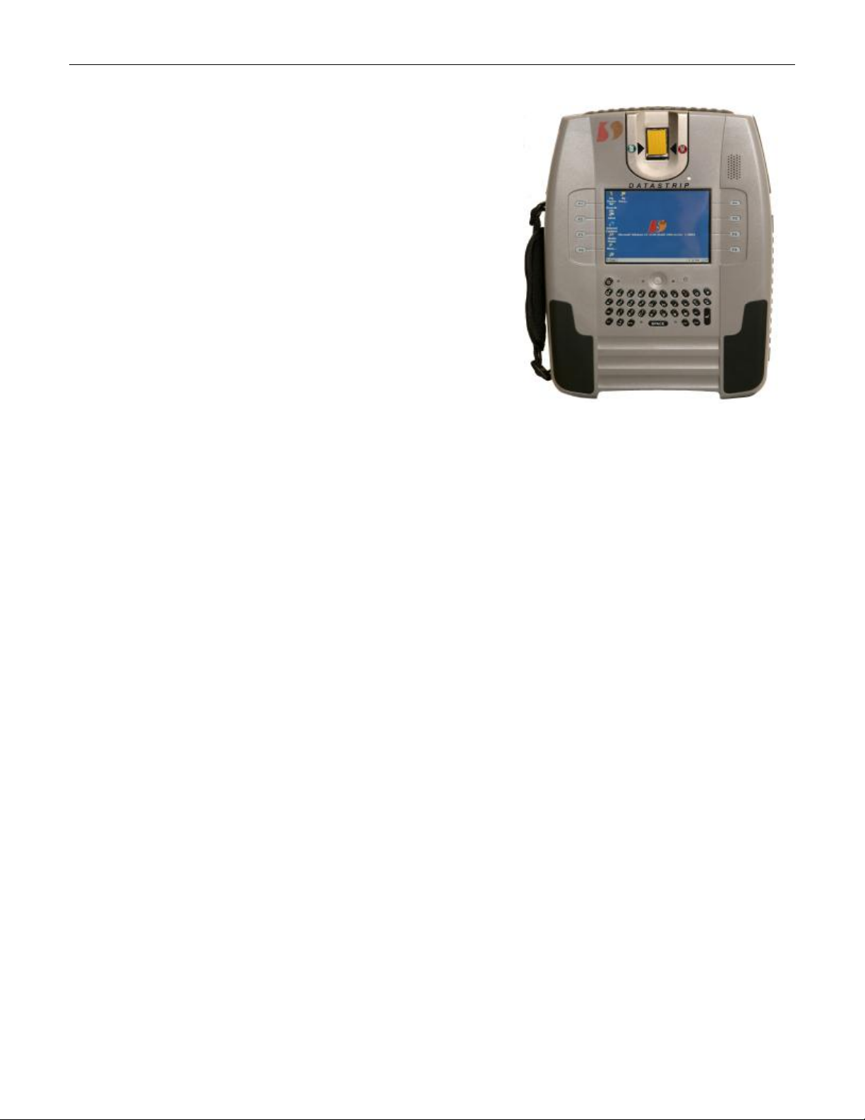
1 Overview
The EasyRead is a member of Datastrip’s DSV3 family of
mobile hand-held biometric terminal products designed for a
wide-range of identification and ID management applications.
The EasyRead is optimized for one-step reading of ePassports;
however, it is able to read a wide variety of other optical or
smart card based credentials containing biometric data. It is
capable of comparing this information with the biometric data
collected by its on-board biometrics sensors (fingerprint and
cameras). It allows an operator to capture biometrics and to
perform quick, remote ID verification or identification while
in the field. The terminal can operate totally standalone, or it
can coordinate with centralized systems via a rich set of
communications interfaces. It is available with remote
communications capabilities that include: 802.11/WiFi,
Bluetooth, and GSM mobile cellular.
Operators can acquire a fingerprint image and remotely
Mobile Terminal
perform 1-to-many identifications against a watch list, or
perform 1-to-1 comparisons for identity verification. Superior matching accuracy is achieved through
AFIS-quality (Automated Fingerprint Identification System) biometric matching algorithms and rugged
biometric sensors.
All of the DSV3 family of mobile terminals are rugged and environmentally sealed units that can be used
in harsh and hostile environments. They are shock resistant (Mil STD 810 compliant) and can withstand
a fall of four feet to a concrete surface. The DSV3 mobile terminals exceed IP 54 specifications for
resistance to dust and water.
The DSV3 is an open platform that comes with a powerful software programming SDK (Software
Developer Kit) that enables customers and system integrators to readily customize the unit for specific
applications and missions. Industry standard interfaces and technologies are used extensively to facilitate
the integration with other systems and to expedite the delivery best of breed solutions to the market. This
approach allows customers to select the technologies and components that are the most appropriate for
their applications and environments.
The flexibility and ruggedness of the EasyRead make it an ideal solution for ID verification and ID
management projects in markets and applications such as:
• Homeland Security • Immigration Control
• Law Enforcement • Airports
• Military Bases and Ships • Transportation
• Travel & Border Control • Financial Institutions
• Seaports • Schools and Universities
+ See section 12 for a detailed description of the ePassport reader subsystem and operation.
5
Copyright © 2009 by Datastrip, Inc. All rights reserved.
Reproduction in whole or in part is prohibited.
4209-00009-000 EasyRead (DSV3-EP) User’s Manual Rev 0E
6/29/2009
2 Unpacking & Inventory
Depending on the number of terminals ordered, your DSV3 units and accessories may be shipped in either
a single-pack box or a multi pack-box. Carefully open the shipping box and use the following inventory
list to verify the contents.
Shipping Box Inventory:
• DSV3 Mobile Biometric Terminal
• Universal (90-240 VAC input) DC power/charging adapter.
• AC power cord for DC power/charging adapter. (Plug depends on country of destination)
• Documentation: User Manual (on CD), End User License Agreement, and Quick-Start Guide.
+ Please retain the shipping box in the event you need to return your product for service.
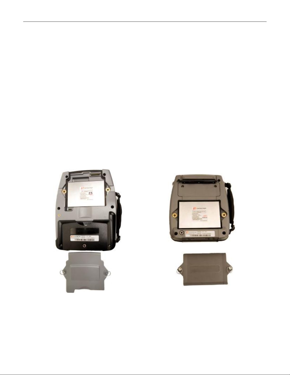
3 Initial Setup
• Each unit is shipped with a Lithium Polymer battery installed as shown below.
• It is recommended that you fully charge the battery before use to maximize operating time before
recharging is required. The EasyRead contains an integrated charging circuit that allows the
batteries to be charged inside the unit whenever the unit is properly connected to the AC adapter.
• The unit may be operated when connected via the AC adapter, regardless of the charge state of the
internal battery.
EasyRead (DSV3-EP)
EasyVerify (DSV3-SP)
+ Please refer to Section 4.4 “Battery Charging and Replacement”, for additional instructions and
safety information.
Copyright © 2009 by Datastrip, Inc. All rights reserved.
Reproduction in whole or in part is prohibited.
6

4209-00009-000 EasyRead (DSV3-EP) User’s Manual Rev 0E
6/29/2009
4 System Overview
The standard DSV3 products come from the factory with a Windows CE .NET, Version 5.00 operating
system, software utilities, and some demo and sample applications. When the unit is powered up, a
standard Windows CE desktop is presented that allows users to launch demonstration programs. The
primary human interface is the touch screen, stylus, QWERTY keypad, and function keys.
Fingerprint
Function
Buttons
Power
Button
Power Status
LED (tri-color)
Speaker
Light Sensor
Function
Buttons
Navigation
Microphone
QWERTY
Programmable LED Status
Indicators
EasyRead (DSV3-EP)
Sensor
Ambient
Button
Keypad
Function
Buttons
Power
Button
Power Status
LED (tri-color)
QWERTY
Keypad
Programmable LED Status
Indicators
EasyVerify (DSV3-SP)
Fingerprint
Sensor
Speaker
Ambient Light
Sensor
Function
Buttons
Navigation
Button
Microphone
4.1 Powering the Unit ON / OFF and System Startup Sequence
The Power Button is located to the top left of the QWERTY keypad as shown in the diagram above. The
power switch has an adjacent tri-color (red/green/yellow) LED, which identifies whether the system is on,
charging, or running low on battery power (see section 4.3).
4.1.1 Power ON
• To power on the mobile terminal from the OFF state, press the Power button, and hold it down
until one beep is heard (less than one second). When the button is released, a rising tone (mid tone
followed by a higher frequency tone) is produced.
• The unit takes approximately 30 seconds to boot up. The display will indicate that the system is
booting. During this time, the BIOS is loaded, and diagnostic testing is performed.
• When the unit finishes powering up, the Windows CE.NET desktop will appear on the display.
4.1.2 Power OFF
• To turn off the mobile terminal, press the Power button for 1 to 15 seconds. The system will
briefly go into Suspend mode and save the WinCE registry contents to non-volatile memory. The
system will then automatically proceed to the OFF state.
• Pressing the Power button for more than 15 seconds commands the unit to perform an emergency
shutdown, and any unsaved information may be lost. An operator should only use the emergency
shutdown procedure if the mobile terminal is not responding.
4.1.3 Suspend Mode
Suspend mode is one of the low power states of the mobile terminal where:
• The USB subsystems are turned off
• The CF card slot is turned off
• The backlight for the LCD and keypad is dimmed
• The processor is put in a low power mode
Copyright © 2009 by Datastrip, Inc. All rights reserved.
Reproduction in whole or in part is prohibited.
7

4209-00009-000 EasyRead (DSV3-EP) User’s Manual Rev 0E
6/29/2009
There are several ways that the mobile terminal can go into Suspend mode from the Power ON state:
• Power Button: The mobile terminal will go into Suspend mode if the operator presses the Power
button for less than 1 sec while the unit is in the fully Power ON state. If the Power button is
pressed for more than 1 sec, the unit will perform a normal Power Off sequence.
• Touchscreen: The touchscreen interface can be used to command the mobile terminal to go to
Suspend mode via the Start/Suspend command.
• Automatic Power Management: The mobile terminal can be configured to go to Suspend mode
automatically (see section 5.3) if the touchscreen or function buttons have not been used for some
(user configurable) amount of time.
4.2 Power Button Operations
Listed below is a summary of what the Power button does (mobile terminal status and the resulting
audible tone indicators) depending on the state of the mobile terminal.
State of the Terminal Tone Type
Unit is OFF
Button pressed Signals ok to release button Beep Tone
Button released The terminal is powered ON Rising Tone
Unit is ON
Button pressed Signals ok to release button Beep Tone
Button released (0 < x < 1 sec) The terminal is goes into Suspend mode None
Button released (1 < x < 15 sec) The terminal is powered OFF normally Falling Tone
Button released (x > 15 sec) The terminal performs an emergency shutdown
WinCE launched Signals the launch of the OS MS Launch Tone
Battery enters an extremely low state System needs attention Warning Tone
Unit is in Suspend
Button pressed Signals ok to release button Beep Tone
Button released (0 < x < 1 sec) The terminal is goes into Resume mode None
Button released (1 < x < 15 sec) The terminal is powered OFF normally Falling Tone
Button released (x > 15 sec) The terminal performs an emergency shutdown
Entering OFF state via power management see section 5.3 Falling Tone
Definitions
• Beep Tone: Shorter high frequency tone
• Rising Tone: Mid followed by a higher frequency tone
• Falling Tone: Mid followed by a lower frequency tone
• Warning Tone: Longer low frequency tone
• MS Launch Tone: Standard Microsoft WinCE start up tone
Warning Tone
Warning Tone
4.3 Power Status LED
The table below shows the states for the Power Status LED. The state of the LED depends on the charge
state of the battery, and whether or not the AC adaptor is connected.
• If red is included in the LED display sequence, this indicates that the battery charge level is very
low or that the battery is charging.
• If yellow is included in the LED display sequence, it indicates that the system is in Suspend mode.
• See section 5.4 for a description of the battery gauge available via WinCE.
• See section 5.3.1 for a description of the available power management states.
Copyright © 2009 by Datastrip, Inc. All rights reserved.
Reproduction in whole or in part is prohibited.
8

4209-00009-000 EasyRead (DSV3-EP) User’s Manual Rev 0E
Quick Release
Quick Release
Qu
ick Release
Quick Release
6/29/2009
Definitions
External Power
Connected?
Battery
Charge State
Power Status
LED Color
Power Status LED Blink Rate
System Powered OFF
WinCE Running
System In Suspend Mode
Yes No Battery Green Very Slow Blink
Yes Charging Green / Red Continuous with Slow Color Blink
Yes Fully Charged Green Very Slow
No OK / Not Low Green Slow Blink
No Low Red / Green Continuous with Color Toggle
Yes No Battery Green Solid
Yes Charging Green / Red Continuous with Color Blink
Yes Fully Charged Green Solid
No OK / Not Low Yellow Slow Blink
No Low Red / Yellow Continuous with Color Toggle
Yes No Battery Yellow Solid
Yes Charging Yellow / Red Continuous with Color Blink
Yes Fully Charged Yellow Solid
• Solid: LED is ON continuously.
• Slow Blink: LED is ON 50% of the time, blinking every 2.5 seconds (50% duty cycle, 2.5 sec period).
• Very Slow Blink: Mostly dark with quick blink approx every 5 seconds (~1% duty cycle, 5 sec period).
• Continuous with Slow Color Blink: LED is ON continuously with a 5 sec period, where color 1 is ON for 4.9 sec
and color 2 is ON for 0.1 sec.
• Continuous with Color Blink: LED is ON continuously, with a 2.5 sec period, where color 1 is ON 2 sec, and
color 2 is ON 0.5 sec.
• Continuous with Color Toggle: LED is ON continuously, alternating evenly between the two colors (50% Duty
Cycle, 2.5 sec Period).
4.4 Battery Charging and Replacement
The terminal uses one 5000 mAH Lithium Polymer battery pack. Under normal operating conditions, the
battery does not need to be removed. The terminal has an internal charging circuit that will charge the
battery whenever the unit is connected to the external AC power adapter.
If the user does want to replace the battery, it may be replaced when the unit is off, or the battery may be
hot swapped when the unit is in Suspend mode. To hot swap the battery, save any work in progress and
put the unit into Suspend by tapping the power button (or via the Suspend command on the Start Menu).
Turn the quick release (quarter-turn) bails on the battery access cover on the rear of the unit. Remove the
old battery and replace it with a charged battery within 30 seconds to prevent the unit from shutting down.
Replace the battery-access cover and re-fasten it by tightening the quick release bails.
Receptacles
Bails
Receptacles
Bails
EasyRead (DSV3-EP) EasyVerify (DSV3-SP)
9
Copyright © 2009 by Datastrip, Inc. All rights reserved.
Reproduction in whole or in part is prohibited.

4209-00009-000 EasyRead (DSV3-EP) User’s Manual Rev 0E
6/29/2009
4.4.1 Battery Capacity and Charging
• The capacity estimates in the following table are for a healthy new battery and are worse case
results that reflect continuous use with all power saving options turned off. Actual capacity
performance will be much better if the power management features are enabled.
• The battery capacity (hours of use) can be extended significantly by using the power savings
options such as: System Idle or Suspend. These power settings are user programmable and details
can be found in Section 5.3 Power Management.
• The charge state of the battery can be observed with the integrated battery gauge features (see
section 5.4).
• The charge time is approximately the same whether the battery is charged with the unit “ON” or
“OFF”.
• When a terminal is left on the shelf in the “OFF” state, the battery will maintain its charge for
approximately one month.
EasyRead (DSV3-EP) EasyVerify (DSV3-SP)
5000 mAH Battery
Capacity (hours of use)
Battery Charge Time
There is also an internal, rechargeable coin cell battery that powers the Real Time Clock for more than 6
months while the unit is off. This battery is automatically recharged by the system, and does not require
any operator service.
P P
5 hours 5 hours
4 hours 4 hours
+ CAUTION! Use ONLY approved replacement batteries and power adapters as provided by Datastrip.
+ CAUTION! Battery has a risk of FIRE, EXPLOSION, or BURNS. DO NOT: short-circuit the battery
terminals; crush, puncture, disassemble or otherwise damage the battery’s case; operate or charge at
temperatures above 40º C or store the battery at temperatures above 100º C; incinerate or immerse in water.
+ DISPOSAL: Always consult and obey all international, federal, provincial/state, and local hazardous waste
disposal laws. Certain jurisdictions require recycling of this spent product.
4.5 Keypad and Function Buttons
The terminal includes a backlit extended QWERTY keypad, and two groups of four backlit function
buttons that are vertically aligned along the left side and right side of the LCD display. These two groups
of function buttons operate identically, and are initially programmed as standard “F1” through “F4” keys
(mapped as cursor / arrow keys). The DSV3 SDK allows these buttons to be software defined (controlled
by custom software).
The Navigation Button is located in the center of the unit just under the LCD display and above the
QWERTY keypad. The Navigation Button is not a mouse control; however, it allows an operator to
navigate through menus and select menu items.
Copyright © 2009 by Datastrip, Inc. All rights reserved.
Reproduction in whole or in part is prohibited.
10
4209-00009-000 EasyRead (DSV3-EP) User’s Manual Rev 0E
6/29/2009
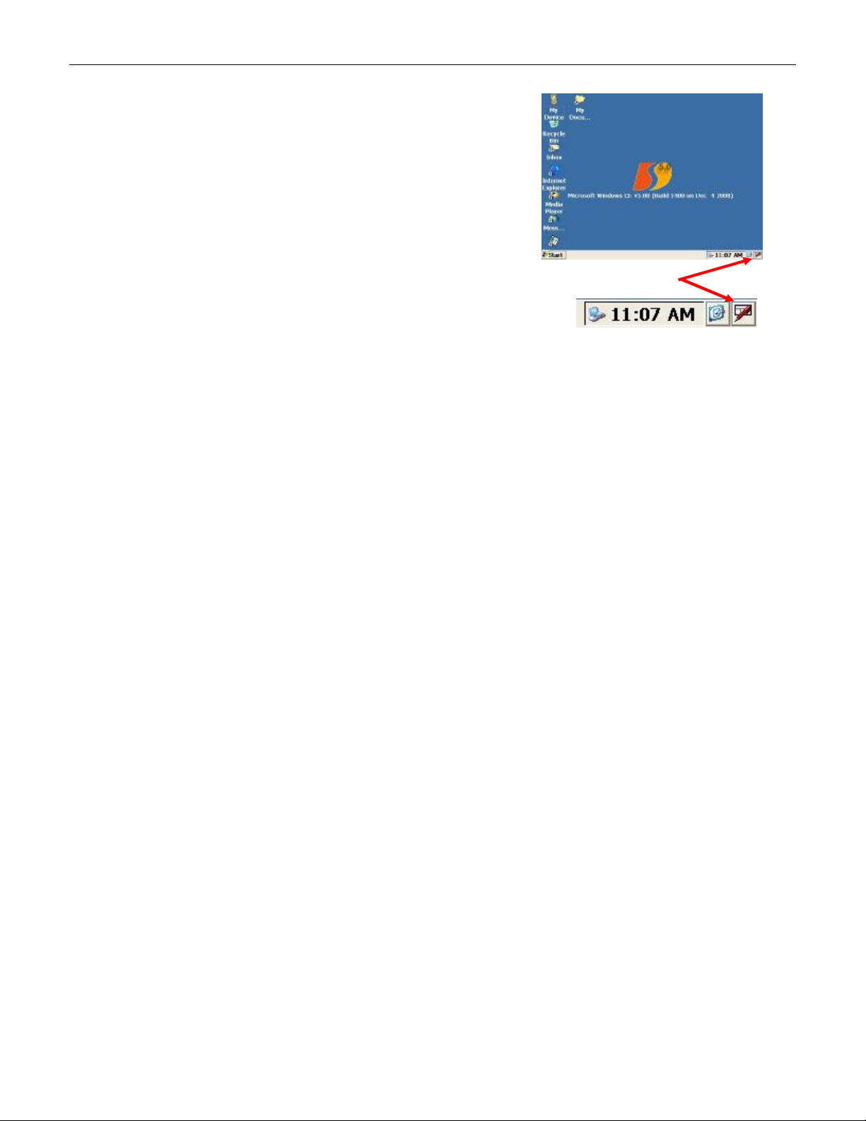
4.6 Software Input Panel / Keyboard
In addition to the extended QWERTY keypad, there is also a
Virtual Input Keyboard (Software Input Panel) that can be
used to enter alpha-numeric information. Tap the Software
Input Panel icon in the bottom right hand corner of the
screen to show or hide the Virtual Input Keyboard / Software
Input Panel.
Software Input Panel Icon
4.7 LCD Display & Touch Screen
The LCD is a color-TFT (Thin Film Transistor) active-matrix display, and features white-LED
backlighting. There is a resistive touch panel overlay, which should only be operated with the included
stylus to help prevent scratching or other damage.
4.8 Fingerprint Sensor
4.8.1 Fingerprint Sensor –NIST FIPS 201/SP 800-76 Compliant
The integrated fingerprint sensor is an 8-bit, grayscale, solid-state, capacitive-touch device that can
capture fingerprint bitmap images measuring 256 pixels wide by 360 pixels high at 508 dpi. Images from
this sensor can be used for a variety of card holder ID validation purposes, including matching, storage,
and extraction of fingerprint minutia templates.
The DSV3 mobile terminals are compliant with fingerprint matching algorithms from a variety of the
industry leading vendors such as: Identix, Cogent, Bioscrypt, Motorola, and NEC. However, the Identix
algorithm is the only algorithm directly available from Datastrip for the DSV3 terminals at this time.
4.8.2 Fingerprint Sensor Calibration
The fingerprint sensor is factory calibrated and tested on every terminal, however, if recalibration is
required for some reason, follow these steps:
• Double tap My Computer and Select Hard Disk/DSV3.
• Double tap the PPCalFt41 utility and press the “Calibrate” button to re-calibrate the fingerprint
sensor. This process may take up to a minute and then a “green” window with a number “1”
should appear to indicate the sensor was successfully calibrated.
• Double tap the DsVerifyFpCaptureTest application. In the lower right hand corner select
“UPEK” and click “OK”.
• Use the “Scan” button to test the fingerprint image quality.
4.8.3 Finger Placement Guidelines
It is important to place the finger properly on the sensing area to enable the device to more quickly
capture a good fingerprint image. Listed below are the guidelines for proper finger placement.
• Finger placement icons: These two icons pictorially indicate the correct (green) and incorrect
(red) way to align the cuticle of your finger with the points of the finger-placement guide arrows.
• Finger placement guide arrows: These arrows should be used as a guide for alignment of the
cuticle part of the finger as described above.
Copyright © 2009 by Datastrip, Inc. All rights reserved.
Reproduction in whole or in part is prohibited.
11
4209-00009-000 EasyRead (DSV3-EP) User’s Manual Rev 0E
Audio Headset
USB Client Port
6/29/2009
4.9 Cleaning the LCD Touch Screen and Fingerprint Sensor
The LCD touch screen and fingerprint sensor require periodic cleaning to remove dirt, oils, grease, dust,
and foreign matter.
• Ensure that the terminal power is OFF and unplugged from any external power source.
• Using standard alcohol wipes, gently wipe the surface of the LCD screen and fingerprint sensor
until it appears clear.
• Allow the cleaning solvent to dry completely before turning the unit on again.
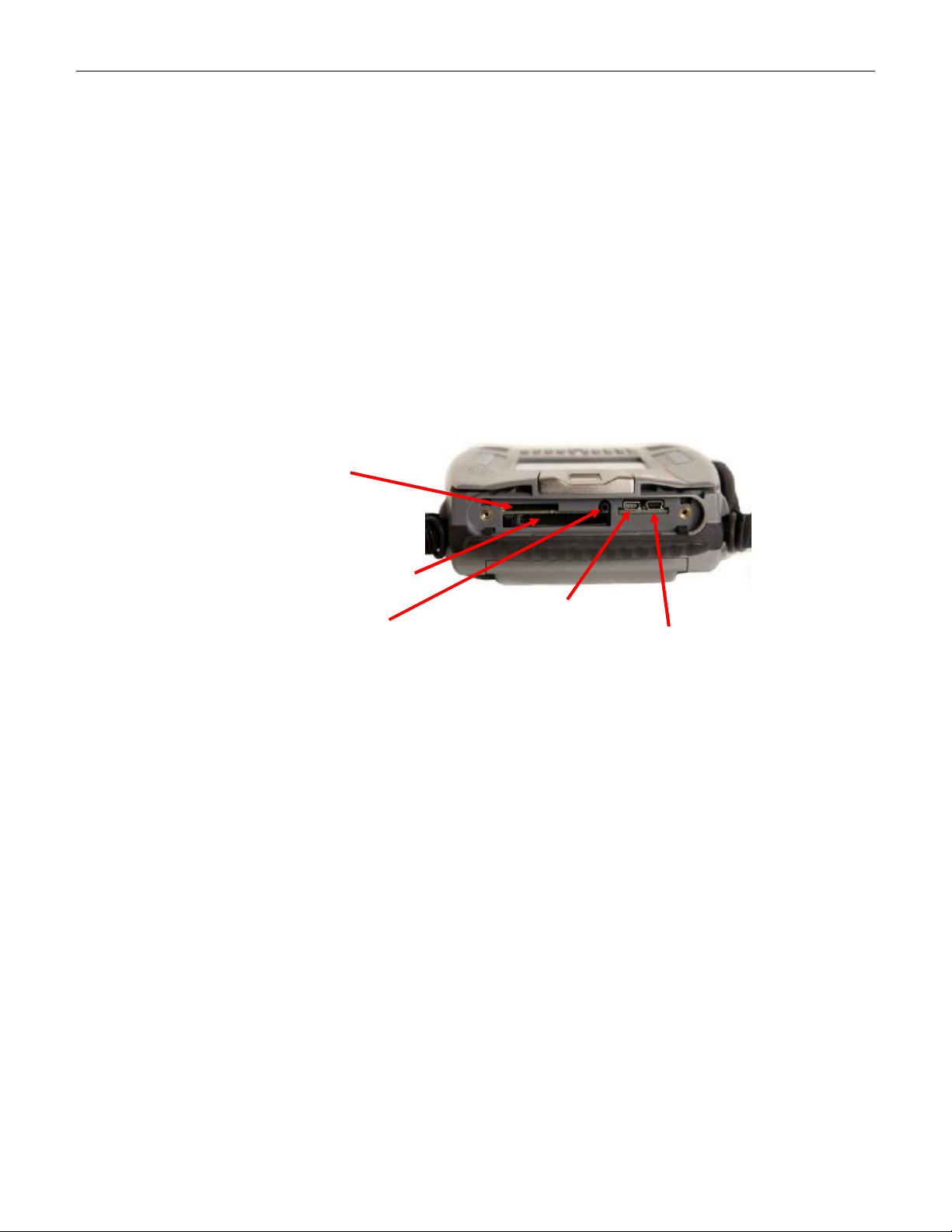
4.10 I/O Port Access
The top rubber end cap on the unit snaps open to reveal the CFIO, SDIO, and onboard wired I/O ports.
To open the top rubber end cap, pull up from the back edge using the two finger indents. The rubber cap
is tethered at two points to prevent it from being lost or misplaced. To close the cover, simply press the
cover into place.
Shown below is the I/O connector panel located on the top of the unit. It contains one mini-USB host
port, one mini-USB client port, one external Compact Flash (CFIO) slot, one Secure Digital module
(SDIO) slot, and the Audio Headset jack.
Secure Digital / SDIO
Compact Flash / CFIO
USB Host Port
4.10.1 USB Ports
There is one USB Host port and one USB client port on the mobile terminal that are accessible under the
rubber I/O port cover. These are USB 2.0 High Speed (480 Mbps) ports; however, they are also
backwards compatible with USB 1.1 Full Speed (12 Mbps) and Low Speed (1.5 Mbps). Additional USB
ports are available on the Docking Station (see section 12).
The USB Host port is used to connect with USB peripheral devices such as a keyboard, a mouse, or flash
memory drives.
The USB Client port enables the mobile terminal to connect and communicate with devices such as PCs
and servers using Active Sync (see section 0). The USB Client port on the top of the terminal is disabled
when the unit is placed in the docking station. There is an alternate USB Client port available on the
docking station for use during this situation.
4.10.2 Compact Flash (CFIO) Slot
The terminal has a Type-I/II Compact Flash slot that is accessible under the rubber I/O port cover. It is
compatible with a range of CF memory and peripheral devices.
4.10.3 Secure Digital Memory Card (SDIO) Slot
The terminal has an SD slot that is accessible under the rubber I/O port cover. It is optimized (recessed)
for Datastrip’s 802.11 peripheral; however, it is a standard SD slot, so a range of SD memory and SDIO
peripheral devices may be used.
Copyright © 2009 by Datastrip, Inc. All rights reserved.
12
Reproduction in whole or in part is prohibited.

4209-00009-000 EasyRead (DSV3-EP) User’s Manual Rev 0E
Ground
Left
Microphone
6/29/2009
4.10.4 Audio Headset Jack
The audio headset jack is a 2.5 mm jack that supports stereo headset and microphone. Shown below is
the pin out required for an appropriate headset.
Right
4.11 Contactless Smart Card Reader
The EasyRead terminal has an integrated Contactless
Smart Card reader subsystem (transceiver and
antennas). The terminal is equipped with two
separate antennas for reading ePassports, since some
countries have placed the contactless smart card chip
in the front cover of the ePassport, while other
countries have place it in the rear cover. The
EasyRead can also be used to read a wide range of
other (non-ePassport) ISO 14443 smart card media.
Either antenna can be used to read these smart card
media; however, the upper antenna is typically more
convenient. Place and hold the media to be read
against the back of the terminal in the center of the
antenna. Once the media is in place, the system will
automatically select which antenna to use.
Smart
Card
Antenna
location
4.12 Optional Peripheral Modules
The terminal can be equipped with a variety of optional peripheral modules and internal optional features.
The list of available options differ from one model of the DSV3 terminal to another. Please refer to the
datasheet for the specific options available for your terminal. Some of the optional modules include:
• Digital Still Camera
• Iris Camera
• Contact Smart Card Reader
• Point & Shoot Scanner
• PROX Card Reader
Some of the available internal optional features include:
• 802.11
• Bluetooth
• Mobile Wireless: GSM (GPRS/EDGE)
• Global Positioning System (GPS)
• Security Access Module
Copyright © 2009 by Datastrip, Inc. All rights reserved.
13
Reproduction in whole or in part is prohibited.

4209-00009-000 EasyRead (DSV3-EP) User’s Manual Rev 0E
6/29/2009
5 Basic Operation
The following sections describe some of the features and functions that are available on the DSV3 family
of products.
5.1 Stylus Usage
A stylus is provided to use with the touch screen for selecting items and entering information (the unit
may also be operated with a standard USB mouse). The stylus can be found in the stylus holder on the
back of the EasyVerify and the front of the EasyRead. Typical actions to perform with the stylus include:
• Tap: Lightly touch the screen once with the stylus to select an object. Tapping is equivalent to
clicking an item with the mouse on your personnel computer.
• Double-Tap: Lightly touch the screen twice with the stylus to open folders and applications.
Double-Tapping is equivalent to Double-clicking an item with the mouse on your personnel
computer.
• Drag: Hold the stylus on the screen and drag it across the screen to select text and images. Drag
within a list to select multiple items.
• Tap-and-Hold: Tap and hold the stylus on an item for a short period until a menu displays a list
of actions available for that item. Tapping and holding is equivalent to right-clicking al computer
mouse button. When you tap and hold, a circle of red dots appears around the stylus to indicate
that the menu will soon pop up. Tap the action you want to perform on the pop-up menu that
appears.
5.2 Touch Screen Adjustments
The touch screen is calibrated during factory acceptance tests. If you wish to recalibrate these setting to
suit your personnel preferences, the following options are available:
• Calibration: If your device is not responding properly to your screen taps, you may need to
recalibrate your screen. Go to the Control Panel, select Stylus Properties and under the
“Calibration” tab, click the “Recalibrate” button and follow the on screen instructions. When you
are told to “press enter” to accept the setting, just tap the screen anywhere, then click the “OK”
button.
• Double-Click Sensitivity: Go to the Control Panel and select Stylus Properties. Double–tap the
checkerboard grid to set the double-tap sensitivity for both speed and physical distance between
the taps. Then double tap the icon below the checkerboard to verify your settings. Click the “OK”
button when done.
• Brightness and Contrast: The display brightness and contrast can be adjusted for different
operating environment lighting conditions. Go to the Control Panel, select Display and under the
“Backlight” tab adjust the slider control then click the “OK” button.
5.3 Power Management
The Power Properties for the terminal can be configured and monitored by double clicking the Power icon
in the WinCE Control Panel. The Battery tab displays the battery gauge / charge status, and the Schemes
tab allows the user to configure the timeout for each of the Power States defined below.
5.3.1 Power Management States
Clicking the Schemes tab allows you to configure when the system enters into the various power
management modes available to maximize battery life. An operator can configure the time the system
must be idle before entering each of the available power management states.
Note: The times configured for each state are cumulative! For example, the time required for the
system to suspend is the sum of the time configured to go to User Idle + the time to go to System Idle +
the time to go to Suspend.
Copyright © 2009 by Datastrip, Inc. All rights reserved.
Reproduction in whole or in part is prohibited.
14

4209-00009-000 EasyRead (DSV3-EP) User’s Manual Rev 0E
Charging State
6/29/2009
The power management states are:
• Fully On
§ Every subsystem in the mobile terminal is on and operational.
• User Idle
§ This state is entered when the touch screen or function keys have not been used for some
(user configurable) amount of time.
§ The backlight is dimmed to save power.
§ All other internal subsystems are on.
§ Tap the screen or give the power button a quick tap to wake up the unit to a Fully On
condition.
• System Idle
§ This state is entered when no major background software tasks are running and the touch
screen or function keys have not been used for some (user configurable) amount of time.
§ In this state, the backlight is dimmed to save power.
§ All other internal subsystems are on.
§ Tap the screen or give the power button a quick tap to wake up the unit to a fully on
condition.
• Suspend
§ This state is entered when no major background software tasks are running and the touch
screen or function keys have not been used for some (user configurable) amount of time.
Suspend mode is indicated by flashing power LED (see section 4.3).
§ In this state, the LCD is turned off and backlight is turned off.
§ USB subsystems are turned off.
§ CF cards are turned off.
§ The Processor is put in low power mode.
§ Tap the screen or give the power button a quick tap to wake up the unit to a fully on
condition.
• Fully Off
§ Everything in the system is off (except the embedded controller).
§ Push the power button to start the unit and return to a Fully On state.
5.4 Battery Gauge
A battery gauge is available in the Control Panel under Power Properties. It provides information about
the about the battery charge level and charging status. Clicking the Battery tab displays the battery gauge.
The charge level of the battery (percentage power remaining) is shown at the bottom of the Power
Properties / Battery tab window.
Battery Charge
Level Summary
Battery Charge Level
Copyright © 2009 by Datastrip, Inc. All rights reserved.
Reproduction in whole or in part is prohibited.
15
4209-00009-000 EasyRead (DSV3-EP) User’s Manual Rev 0E
6/29/2009
5.4.1 Charging States
The Power Properties / Battery tab window also shows that state of the internal battery charger. There
are three charging states.
• Main Battery: The terminal is operating on battery power and no external AC adapter is
connected.
• External: External AC adapter is connected and the battery is fully charged.
• Charging: External AC adapter is connected and the battery is charging. The unit operates
normally while simultaneously charging the battery.
5.4.2 Battery Charge Level States
The charge level state of the battery is also listed in the Power Properties / Battery tab window. There are
three charge level states. When the battery gauge is “Very Low”, the battery should be immediately
charged by connecting the unit to an AC adapter or the unit will automatically shut down when the
voltage level drops below the minimum threshold.
• Good: Battery charge is Good
• Low: Battery charge is Low (<10% remaining)
• Very Low: Battery charge is Very Low / Critical (4% remaining)
5.4.3 Other Indicators
There are three user warnings that occur when the battery level is “Very Low”: See sections 4.2 and 4.3
for the LED and tone indicator states that also provide user feedback regarding battery charge levels and
charging states.
• The power LED alternately flashes Red and Green (see section 4.3)
• A warning message pops up “Main Battery Very Low”. This warning will repeat itself
periodically until the condition clears or the unit automatically shuts down.
• An error beep sounds when the battery charge level is critical.
5.5 Creating Desktop Shortcuts
To create desktop shortcuts, locate the application for which you want to create a shortcut. Tap and hold
the stylus on the application until the options menu pops up. Select Copy and go to the directory where
you want to put the shortcut. Tap and hold the stylus until the options menu pops up and select “Paste
Shortcut”.
5.6 Safe Boot Mode
The system provides a mechanism that permits the recovery of lost or damaged
operating system files via a “Safe Boot” mode. This mechanism is similar to
Microsoft Windows Safe Mode that is available on PCs. If one or more
operating system files have been damaged or inadvertently deleted, when the
unit is turned on it will automatically boot-up into a smaller, limited function
version of Windows CE that will permit the recovery of the files or allow them
to be replaced or overwritten. This permits the unit to be repaired, and then
subsequently rebooted using the full version of Windows CE. Safe Boot mode
can also be accessed on demand by holding down the F1 key while turning on
the power to the unit. A special bitmap will appear indicating that the unit is
booting-up in Safe Boot mode.
6 Software Utilities
All of the utilities listed below except “DsVerify2About” are located in the My Device\Hard Disk\DSV3
directory. The “DsVerify2About” is a hidden file in the \My Device\Windows directory. There are
additional demonstration programs available as source code for custom software development in the
Datastrip MT SDK (sold separately).
Copyright © 2009 by Datastrip, Inc. All rights reserved.
Reproduction in whole or in part is prohibited.
16
4209-00009-000 EasyRead (DSV3-EP) User’s Manual Rev 0E
6/29/2009
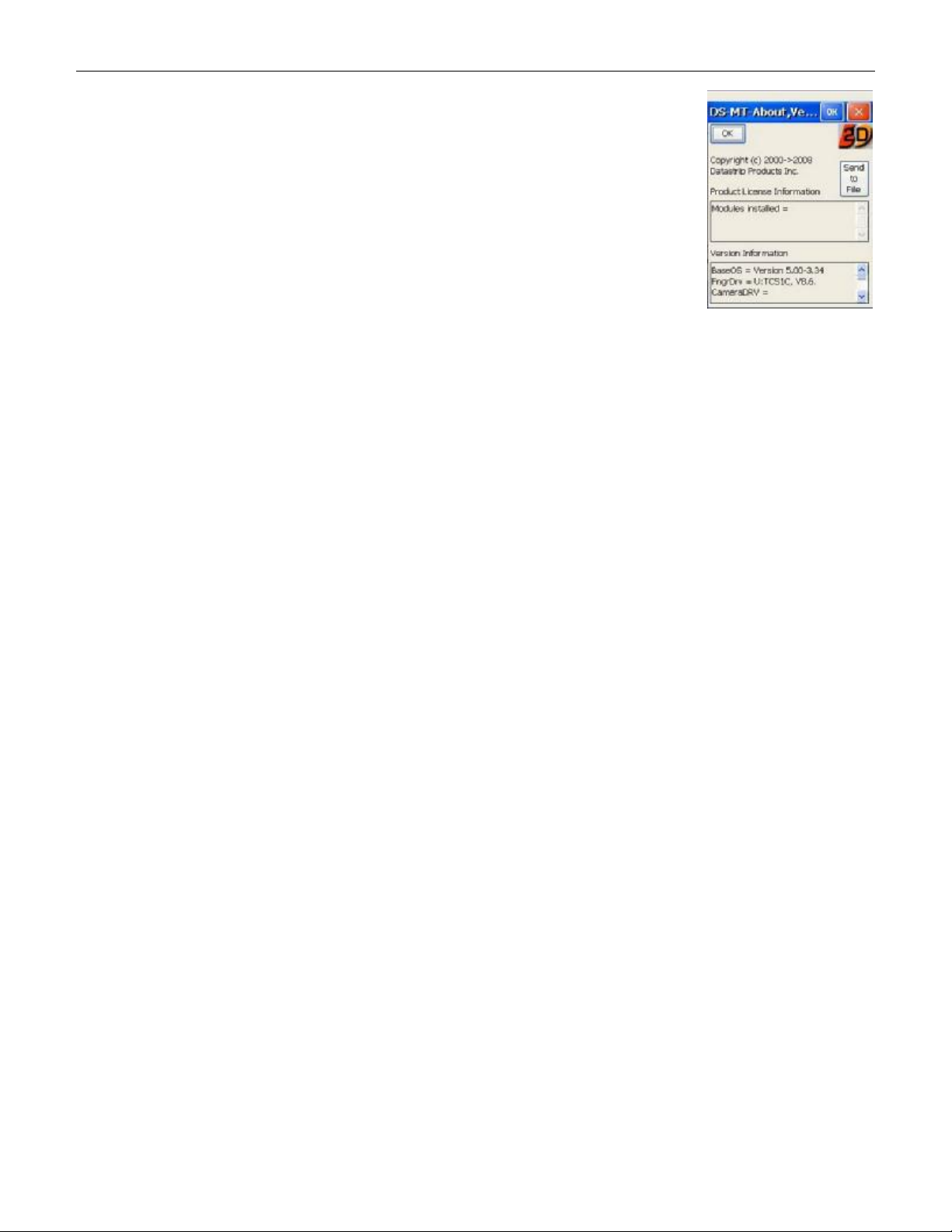
6.1 Software Version Utility (DatastripDSVerify2About.exe)
This utility reports the Operating System (OS) Version, the versions of all
Datastrip specific drivers and components, software license settings, the unit
serial number, and the hardware configuration. To run this utility:
• Click Start\Run
• Click Browse then double tap the Windows folder
• Scroll over and double tap the application: DatastripDsVerify2About.exe
• Click “OK”
This version information can be saved to a file by clicking on the “Send to File”
button.
6.2 DsVerify Registry Install Utility (DsVerifyRegInst.exe)
This application registers all of the Datastrip specific components of the terminal that are needed to
read/write smart cards, scan documents, operate the fingerprint sensor, and so forth. It is typically run
after a software update to register the components in sequence, and it reports any errors if it does not
succeed. If it finishes successfully, there will be a pop-up message box indicating “Finished
Registration”. It can take up to a minute or two to complete this process.
Internally, this program calls regsvrce.exe to register each ActiveX control so that the interface
presented by the ActiveX control will be available for application use. This is usually followed by
RegistrySaver.exe (or Suspend) to make sure that the altered registry is written to flash memory for
future use. When this application is invoked, it queries the user for the specific mobile terminal type
(DSVII-SC, DSVII-SW, DSVII-PA, DSV3-SP, or DSV3-EP) and writes the appropriate platform type
information into the registry along with the other registration information.
6.3 DsVerify Registry Saver Utility (RegistrySaver.exe)
This application is used to save the current registry settings to flash memory. This is very useful after
adding applications (or applications components such as ActiveX controls) that require some aspect of the
behavior to be registered. When the terminal is powered-on, the saved registry is read and used as part of
WinCE startup. Datastrip ActiveX components are registered (see DsVerifyRegInst application) and
then the registry settings are saved using this application. The registry can also be saved by hitting the
Start/Suspend function; however, this application is provided to save the registry to non-volatile memory
without having to warm-start the unit.
6.4 Fingerprint Capture Utility (DsVerifyFpCaptureTest.exe)
This application demonstrates the capabilities of the integrated fingerprint image sensor, and it provides
a means of exercising the fingerprint imaging system. The application has several buttons that allow a
user to Scan to the Display or Scan to File. Since this application is provided as source code in the
SDK, it is often used as an example for developers to observe how typical application software can
interface to the fingerprint subsystem.
7 Loading Software and Firmware
7.1 Loading DSV3 Software Updates
The DsVerify2SoftwareUpdate application permits the user to download software updates from several
source locations are as list below:
• CAB files located on a CF memory card: call Storage Card
• CAB files located on a USB flash drive: call Hard Disk 2
• CAB files loaded from an FTP server, (requires a username and password to a valid account).
Copyright © 2009 by Datastrip, Inc. All rights reserved.
Reproduction in whole or in part is prohibited.
17

4209-00009-000 EasyRead (DSV3-EP) User’s Manual Rev 0E
6/29/2009
7.1.1 DSV3 Software Update Procedure: Using a CF Card
NOTE: It is recommended that upgrades be done with the unit operating on the AC adapter to ensure that
the unit does not lose power during this procedure.
• Insert the CF Card containing the new CAB file into the external CF slot.
• Power up the DSV3 terminal.
• When the device is finished booting, navigate to My Device\Hard Disk\DSV3.
• Double tap the DsVerify2SoftwareUpdate utility.
• Scroll through the options on the Server scroll box and select the Storage Card entry (you must
scroll down to make selection).
• Username and Password are not necessary for this procedure
• Select most recent appropriate source file
• Click Update
• Click Reboot (The registry will be cleared prior to shutdown).
• Power up the unit.
• The DSV3 registration program will automatically open. Select the button for the device that you
are registering (DSV3-SP or DSV3-EP). Select [OK] and wait.
• Click [OK] in the “Hurray!” box when it appears, then close the application window.
• Navigate to My Device\Hard Disk\DSV3.
• Double tap the Registry Saver program (RegistrySaver.exe) to launch it.
• Double tap the PPCalFt41 utility and press the “Calibrate” button to initialize the fingerprint
sensor. Once complete, a “green” window with a number “1” should appear to indicate the sensor
was successfully calibrated.
• Double tap the DsVerifyFpCaptureTest application. Look in the lower right hand corner to
ensure that the UPEK button is selected. You can use the Scan function to test the fingerprint
image. DO NOT use the Calibrate button on this screen since it does not work with the
fingerprint sensor in the DSV3. When done, click “OK” to exit the program.
7.1.2 DSV3 Software Update Procedure: Using a USB Flash Drive
To load a software update from a USB flash memory device, follow the procedure from section 7.1.1 with
the following changes:
• Insert a USB Flash drive (instead of a CF Card) into the USB Host port on the DSV3 terminal.
• Inside the DsVerify2SoftwareUpdate utility, select Hard Disk 2 option from the Server scroll box
(instead of selecting Storage Card).
7.1.3 DSV3 Software Update Procedure: Using an FTP site
NOTE: It is recommended that upgrades be done with the unit operating on the AC adapter.
• Power up the DSV3 terminal.
• When the device is finished booting, navigate to My Device\Hard Disk\DSV3.
• Double tap the DsVerify2SoftwareUpdate utility.
• Scroll through the options on the Server scroll box and:
§ Select ftp.datastrip.net if you have access to the Datastrip FTP server
§ Select ftpserv2003 if you are using another valid FTP site.
• Enter a valid Username and Password.
• Click Connect.
• Select most recent appropriate source file.
• Click Download and wait for message “Download complete”.
• Click Update.
• Click Reboot.
• Power up the unit.
Copyright © 2009 by Datastrip, Inc. All rights reserved.
Reproduction in whole or in part is prohibited.
18

4209-00009-000 EasyRead (DSV3-EP) User’s Manual Rev 0E
6/29/2009
• The DSV3 registration program will automatically open. Select the button for the device that you
are registering (DSV3-SP or DSV3-EP). Select [OK] and wait.
• Click [Ok] in the “Hurray!” box when it appears, then close the application window.
• Navigate to My Device\Hard Disk\DSV3.
• Double tap the Registry Saver program (RegistrySaver.exe) to launch it.
• Double tap the PPCalFt41 utility and press the “Calibrate” button to initialize the fingerprint
sensor. Once complete, a “green” window with a number “1” should appear to indicate the sensor
was successfully calibrated.
• Double tap the DsVerifyFpCaptureTest application. Look in the lower right hand corner to
ensure that the UPEK button is selected. You can use the Scan function to test the fingerprint
image. DO NOT use the Calibrate button on this screen since it does not work with the
fingerprint sensor in the DSV3 product family. When done, click “OK” to exit the program.
7.2 Loading Smartcard Firmware Updates
The procedure for updating the smartcard firmware is as follows:
• In the directory My Device\Hard Disk\DSV3 folder, run the utility DsVerifyCleanUp and select
the option Clear SCM Firmware. Answer “OK” to the question “Are you REALLY sure”.
• Reboot the terminal.
• When the device is finished booting, navigate to the My Device\Hard Disk\DSV3 folder.
• Open the DSV3_SCM_Firmware folder.
• Double tap the utility FlashIt
• Tap the button “Open bin file” and navigate to My Device\ Hard
Disk\DSV3\DSV3_SCM_Firmware
• Select the version of firmware that you are changing to and click “OK”.
• Status should read “Binary file is valid”.
• Tap the Download button.
• Reboot the terminal to complete update.
7.3 Loading Flash Memory Updates
The various flash areas in the DSV3 can be updated by using the utility program
“DSV3FlashUpdate.exe”, located in the “\Hard Disk\DSV3” folder. This application allows these areas
of the flash to be updated:
• Embedded Controller
• Splash Screen bitmap
• SafeBoot OS image
• BIOS
The procedure for updating the Flash Memory firmware is as follows:
• Copy the new flash update file that is to be loaded onto the unit onto a Compact Flash card, and
insert the card into the mobile terminals.
• Browse to “My Device\Hard Disk\DSV3\” and run “DSV3FlashUpdate.exe”.
• Select one of the four buttons displayed as follows:
§ Update BIOS
§ Update SafeBoot OS
§ Update Splash Screen
§ Update EC
Copyright © 2009 by Datastrip, Inc. All rights reserved.
Reproduction in whole or in part is prohibited.
19

4209-00009-000 EasyRead (DSV3-EP) User’s Manual Rev 0E
6/29/2009
• Hit the File Selection button to choose which file to download, or Cancel to abort.
• Using the File Dialog box, find, and select the file you wish to download, then hit “OK”.
• The application will then display the file name and path of the file that was selected, and prompts
the user to verify that it is the correct file to use. Select the button labeled “Yes, Proceed with
update” to begin the flash update process.
• If the Embedded Controller was selected to be updated, a message is displayed noting that after
the update, the terminal will power-down. This is normal operation.
• Upon completion of the flash update, a status message box appears indicating the success or
failure of the process. If a failure occurs, the reason for the failure is provided.
• With all updates with the exception of the Embedded Controller, the user is then placed back to
the main screen of the app (4 update buttons). The user may then update another area, or exit the
application.
7.4 Loading Digital Still Camera Firmware Updates
The DSC Firmware Update Utility is a “stand-alone” program which can be used to update the firmware
in the DSC camera module. The procedure for updating the Digital Still Camera firmware is as follows:
• In the directory My Device\Hard Disk\DSV3, run the utility DSC_Firmware_update.exe.
• The application displays the current version number of the camera firmware and asks the question,
“Do you want to update the camera firmware?”
• If you answer “Yes”, then browse to the directory
My Device\Hard Disk\DSV3\DSV3_DSC_Firmware, select the latest firmware version, and
double-click on it, or select it and hit “OK”.
• Wait for the camera to update its firmware. Note: After the firmware is updated, the camera
illumination LED will blink 10 times.
• Reboot the terminal to activate the new firmware.
Copyright © 2009 by Datastrip, Inc. All rights reserved.
Reproduction in whole or in part is prohibited.
20

4209-00009-000 EasyRead (DSV3-EP) User’s Manual Rev 0E
6/29/2009
8 EasyRead (DSV3-EP) Product Specifications
Physical Characteristics
Dimensions:
Weight:
170(W) x 229(H) x 75(D) mm,
(6.7 x 9.0 x 3.0 in)
1.42 Kg (3.1 lbs) with battery
User Interface
Display:
Touch Screen:
Keypad:
Function Buttons:
Navigation Joystick:
Power Button:
Stylus:
3.7” color LCD, transflective TFT,
VGA, 640 (H) x 480 (V), landscape
Indoor/Outdoor viewable (backlit)
Integrated resistive touch panel
37 key extended QWERTY keypad (backlit)
2 x 4 function keypad (backlit)
5 position: up, down, left, right, enter (backlit)
Recessed (backlit)
Integrated stylus holder
Optional tethered stylus
Hardware/Software
Processor:
Flash Memory:
DRAM Memory:
Operating System:
AMD LX800 Geode (x86),
500 MHz, Integrated FPU
256MB, expandable to greater than 1GB
256MB 64-bit DDR, expandable to 1GB
Microsoft® WinCE.Net V5.0
Power Systems & Management
Battery:
Charging
External DC Power:
AC Adapter:
5000 mAH Smart Battery, Field Replaceable
Rechargeable Li Ion Polymer 7.4 V,
Integral Charging and Protection Circuitry
Integrated internal charger
11.4 to 19VDC
Out:12VDC; In:100-240VAC, 30W, 50-60Hz
I/O, Audio, & Peripherals
Interfaces and
Wired I/O:
Audio:
Onboard (under top cap)
USB 2.0 Host: mini-A (x1)
USB 2.0 Client mini-B (x1)
CF Type I/II external interface (x1)
SDIO interface (x1) - for 802.11
via Docking Station
USB 2.0 Host: standard A (x2)
USB 2.0 Client: standard B (x1)
Ethernet: 10/100 RJ45 (x1)
RS-232 DB9 (x1)
Speaker (750 mW)
Environmental Characteristic
Temperature:
Relative Humidity:
Drop Resistance:
Weather Resistant:
Operation: 0° to +40° C (32° to 104° F)
Storage: -20° to +60° C (-4° to 158° F)
< 90% at +40° C Non-condensing
Exceeds MIL-STD 810F
Ingress Protection: IP54
Contactless Smartcard Reader
Specification:
Operating Frequency:
ISO 14443 A/B
13.56 MHz
Optical Scanner
Scan Area:
Standard
Symbologies:
Optional
Symbologies:
Illumination:
Software Interface:
124(W) x 42(H) mm, 4.88(W) x 1.65(H) in
OCR: OCR B
2D Codes: PDF417
1D Codes: Code 39, Code 93, Code 128,
UPC/EAN/JAN, Hong Kong 2 of 5, Interleaved
2 of 5, NEC 2 of 5, Matrix 2 of 5, Straight 2 of
5, Code 11, Codabar, MSI Plessey,
Pharmacode, DataBarTM
OCR: OCR A, MICR
2D Codes: QR Code, Data Matrix, Aztec
Code, Maxicode, Micro QR Code, Codeblock,
Composite Code
Near IR and Visible
HID mode and Virtual Comm mode
Biometric Sensors
Fingerprint Sensor:
Digital Still Camera:
(future option)
Iris Camera:
(future option)
FIPS 201 / SP 800-76 Compliant
Capacitive solid-state sensor, 8 bit grayscale
Resolution: 508 dpi (256 x 360 pixels)
Sensor Area: 12.8 x 18.0 mm; ESD: 15 KV
3.2 M pixel, 24-bit full color
Depth of Field: 0.6 to 5.1 meters
Illumination: Preview and Flash
Full SDK Support
1.3 M pixel sensor , NIR illuminators,
Image Resolution: VGA: 640(W) x 480(H)
Full SDK Support
Wireless LAN (optional)
Specification:
Security Protocols:
Antenna:
IEEE 802.11b/g, 2.4 to 2.5 GHz , DSSS
WEP, WPA, WPA2, LEAP, EAP-FAST,
EAP-TLS, EAP-TTLS, PEAP 0
(PEAP-MSCHAP),PEAP 1 (PEAP-GTC)
Internal
Bluetooth® Wireless (optional)
Specification:
Antenna:
Bluetooth® Version 1.2 Class 2
Internal
Mobile Wireless (optional)
GSM:
Quad Band GSM: 850/900/1800/1900 MHz
EDGE (E-GPRS) multi-slot class 12
(max 236.8 Kbps)
GPRS class 12 (max 86 Kbps)
Antenna: internal; AT Command Interface
Global Positioning System (optional)
GPS:
Protocols:
SDK Support:
16 channel, L1=1575.42 MHz
NMEA-0183, RTCM V2.2, UBX binary
GPS dedicated AT commands
Security Access Module (optional)
SAM Slots:
0 or 1
PROXIMITY Card Reader (optional)
Frequency:
125 KHz
Docking Station (optional)
Wired I/O:
Battery Charging:
Power Input:
Dimensions:
USB 2.0 Host: standard A (x2)
USB 2.0 Client: standard B (x1)
Ethernet: 10/100 RJ45 (x1)
RS-232 DB9 (x1)
Supplies power to charge batteries inside the
mobile terminal
12 VAC, 1.7 mm DC power jack
Footprint: 162(W) x 178(L) mm
[6.6”(W) x 7.0”(L)]
Copyright © 2009 by Datastrip, Inc. All rights reserved.
21
Reproduction in whole or in part is prohibited.

4209-00009-000 EasyRead (DSV3-EP) User’s Manual Rev 0E
6/29/2009
9 Regulatory Compliance Statement
The DSV3 products are in conformity with the requirements of the Low Voltage Directive (72/73/EEC)
and the EMC directive (89/336/EEC) as amended by (93/68/EEC).
FCC Declaration:
This equipment has been tested and found to comply with the limits for a Class B digital device, pursuant
to part 15 of the FCC Rules. These limits are designed to provide reasonable protection against harmful
interference in a residential installation. This equipment generates, uses, and can radiate radio frequency
energy and, if not installed and used in accordance with the instructions, may cause harmful interference
to radio communications. However, there is no guarantee that interference will not occur in a particular
installation. If this equipment does cause harmful interference to radio or television reception, which can
be determined by turning the equipment off and on, the user is encouraged to try to correct the
interference by one or more of the following measures:
• Reorient or relocate the receiving antenna.
• Increase the separation between the equipment and the receiver
• Connect the equipment into an outlet on a circuit different from that to which the receiver is
connected.
• Consult the dealer or an experienced radio/TV technician for help.
WARNING: Changes or modification to Datastrip’s mobile terminal not expressly approved by the
party responsible for assuring compliance could void the user's authority to operate the equipment
in a safe or otherwise regulatory compliant manner.
EasyRead (DSV3-EP)
Copyright © 2009 by Datastrip, Inc. All rights reserved.
Reproduction in whole or in part is prohibited.
22
EasyVerify (DSV3-SP)

4209-00009-000 EasyRead (DSV3-EP) User’s Manual Rev 0E
6/29/2009
10 Software Demo Applications
10.1 Smart Card Reader & Scanner Demo (SuperViewer.exe)
This application demonstrates the primary features of Datastrip’s mobile terminals: reading optical
media, reading smart card media, and performing one-to-one fingerprint matching. The SuperViewer
application only reads and decodes media that contains Datastrip-formatted information payloads.
The following types of smart card media are supported by SuperViewer:
• ISO 14443 Contactless Smart Cards
• ISO 7816 Contact Smart Cards (only supported on units equipped with the optional ISO 7816
contact smart card reader module)
The following optical symbologies are supported by SuperViewer (on units equipped with an optical
scanner).
• Datastrip2D and 2DSuperscript Two-Dimensional Barcodes (not support on DSV3)
• PDF417
• OCRB
• Linear Barcodes
When SuperViewer application is launched, the Main Screen is displayed and the unit is ready to scan a
document or read a smart card. The application automatically reads and decodes a submitted document
and the result is displayed in the Photo, Text, and Fingerprint windows. If the default icon or text is
displayed, the document did not contain that type of data.
If a fingerprint was stored on the document, the application will also perform a one-to-one match of a
fingerprint stored on the document to the fingerprint captured by the on-board fingerprint sensor. This
demonstrates a typical scenario of ID verification (verifying that a card holder is the same person whose
fingerprint is stored on the document).
Main Screen
Clicking the Datastrip logo will return the user to the Main Screen and will reset
the scanner subsystem (if the unit contains an optical scanner subsystem). On the
Main Screen, a user can perform the following operations:
• Clicking on the ‘toolbox’ button will open the Configuration Screen.
• Clicking on the ‘OK’ or ‘X’ will exit the application.
• Clicking on the Photo, Text, or Fingerprint windows expands that
window
Configuration Screen
On the Configuration screen, the following operations are available:
• Clicking on the ‘FP Settings’ button will open the fingerprint threshold
setting screen. Refer to the Fingerprint Settings Screen section below for
details.
• Clicking on the ‘Scan Settings’ button will open the scanner settings
screen. Refer to the Scanner Settings Screen section below for details.
• Clicking on the ‘Timer Settings’ button opens the “Display Timer Diagnostics” screen. To use this
feature, you must first “Auto Hide” the windows task bar by clicking
Start/Taskbar_and_Start_Menu and checking the ‘Auto Hide’ box. In The SuperViewer
application, check the “Display Timer Diagnostics” box and return to the Main Screen. The next
document scanned will be timed and recorded on the bottom line of the display as (Scan: Find:
Copyright © 2009 by Datastrip, Inc. All rights reserved.
Reproduction in whole or in part is prohibited.
23

4209-00009-000 EasyRead (DSV3-EP) User’s Manual Rev 0E
6/29/2009
Decode: Total). e.g. S:5.3 F:0.1 D:0.6 T:6.0.
• Clicking on the ‘Decode Settings’ button will open the Find Decode Settings screen. Refer to the
Find Decode Settings Screen below for details.
• Clicking on the ‘General Settings’ button will open the General Settings screen. To use the
feature, check the “Use GUI Buttons” box, and return to the Main Screen. The GUI buttons
“Photo”, “Text”, and “Fingerprint” will be displayed above the windows.
• Clicking on the “Datastrip” logo button will bring the application back to the Main Screen.
• Clicking on the ‘Toolbox’ has no effect.
• Clicking on the ‘OK’ or ‘X’ will exit the application.
Fingerprint Settings Screen
On the Fingerprint Settings screen, a user can configure the thresholds used by
the fingerprint matching algorithms. Cogent and Identix are the different
fingerprint algorithms that can be licensed for use on the DSV3 terminals. A
higher number tells the system to require a better match of the fingerprints.
Typical threshold values are:
§ Cogent: 1000
§ Identix: Low = 200, High= Not used
• Clicking on the ‘OK’ will save the settings and return the application to
the Configuration screen.
• Clicking on the ‘Cancel’ or the ‘X’ will abort any changes to the settings
and return the application to the Configuration screen.
Scanner Settings Screen
On the Scanner Settings screen, a user can configure parameters for the optical
scanner. This is only necessary for DSVII mobile terminals equipped with an
optical scanner, and does not apply to the DSV3 product family.
Find Decode Settings Screen
On the Find Decode Settings screen, a user configures the type of optical
symbology the system will decode. Only one symbology at a time can be
selected.
• Select the type of ‘symbol’ that the unit will Find and Decode from this
screen. The choices are Datastrip, OCRB, PDF417, or Barcode.
§ Datastrip: Datastrip2D and 2DSuperscript two-dimensional
barcodes. (Not supported by DSV3 terminals.)
§ OCRB: OCRB text
§ PDF417: PDF417 two-dimensional barcode
§ Barcode: a variety of linear (1 dimensional) barcodes
• Clicking on ‘OK’ will save the settings and return the application to the Configuration screen.
• Clicking on the ‘Cancel’ or the ‘X’ will abort any changes to the settings and return the application
to the Configuration screen.
Copyright © 2009 by Datastrip, Inc. All rights reserved.
Reproduction in whole or in part is prohibited.
24

4209-00009-000 EasyRead (DSV3-EP) User’s Manual Rev 0E
-
2048 x 1536 (3.2M pixels)
1632 x 1232 (2.0M pixels)
1280 x 1024 (1.3M pixels)
800 x 600 (480K pixels)
640 x 480 (307K pixels)
Automatic, OFF,
10%
Automatic, OFF, Always ON
25% to 100% in increments of 25%
25% to 100% in increments of 25%
OFF, 50 Hz, 60 Hz
ON, OFF
320 x 240, 160 x 120
Normal, Less Sharp, More Sharp
Automatic, Sunlight, Outdoor
shadow, Fluorescent, Tungsten,
LED
x1, x2
6/29/2009
10.2 Digital Still Camera Demo Application (DsVerifyStillCameraTest.exe)
This application is used in conjunction with the optional Digital Still Camera (DSC) hardware module to
demonstrate the capabilities of the camera subsystem. The DSC is a currently available option on the
EasyVerify (DSV3-SP), but is not yet available on the EasyRead (DSV3-EP).
After starting the application, the LCD displays preview images which are used to align the subject in
preparation of taking a snapshot. After aligning the subject in the display, pressing F1 will turn on the
preview illumination (if selected in the settings), and then pressing F1 a second time will capture and save
the target image. If the preview illumination is not configured, pressing F1 once will capture and save the
target image. Digital zoom can be controlled via the “Settings” menu or by using the F2 and F3 buttons:
• F3 = x2 digital zoom
• F2 = x1 digital zoom
Snapshots taken and stored by the camera may be viewed on the display via the menu selection “FILE>Display latest Snapshot”. This will display the last snapshot acquired by the camera. The user can then
navigate to previous and next snapshots via the “FILE->Previous Snapshot” and “FILE->Next Snapshot”
menu selections. Once the user is done reviewing snapshots, selecting “FILE->Exit snapshot display
mode” will return the camera to the previewing state.
An external USB or compact flash storage card can be used for storing snapshots to conserve the
embedded non-volatile memory. All captured images are stored in 24-bit color depth (full color) BMP
files and are stored in the following folder: depending on the media used:
• Internal non-volatile memory: /Hard Disk/DSV3/My Documents
• External USB memory: /Storage Card/DSV3/My Documents
• External CF memory: /Hard Disk2/DSV3/My Documents
Changes to the camera settings can be made via the “Settings” menu selection, and the settings are stored
in the registry and restored the next time the application is run. The Digital Still Camera settings include:
Setting Selections Available Description of Setting
Brightness
Capture Size
Contrast
Flash Mode
Flash Intensity Still
Flash Intensity Preview
Flicker Cancellation
Preview Illumination
Preview Size
Sharpness
White Balance
Zoom
2.0 F-stops to +2.0 F-stops Controls the amounts of light during exposure. The larger the F-stop, the
more bright the image will appear.
- 100% in increments of 10%
Improves image quality when the camera is used in an environment
Specifies whether or not to use flash illumination during preview mode.
Used to select the size of the preview image displayed on the DSV3
Used to provide the equivalent of two lenses with different focal lengths.
Used to select the size of the snapshot image to acquire. Values indicate
the height and width of the image in pixels.
Used to adjust the visual properties of an image that makes an object in
an image distinguishable from other objects and the background.
Used to specify the flash (illumination) operation mode..
Controls the intensity of the flash when taking snapshots.
Controls the intensity of the flash when previewing a scene prior to
taking a snapshot.
containing fluorescent lighting. Flickering of fluorescent lighting is
caused by alternating current reversals occurring 50 to 60 times a second.
screen. Values indicate the height and width of the preview image.
This setting softens or sharpens areas in the image where an edge
changes from one brightness level to another.
Controls the process of removing unrealistic color casts, so objects which
appear white in the scene being captured are rendered white in the
photograph. Specify the setting closest to the environment in which the
snapshot is being taken.
X1 is normal operation, X2 is the “zoomed” mode.
Copyright © 2009 by Datastrip, Inc. All rights reserved.
25
Reproduction in whole or in part is prohibited.

4209-00009-000 EasyRead (DSV3-EP) User’s Manual Rev 0E
6/29/2009
10.3 DsCameraScannerEPTest.exe (Virtual Comm Mode Demo App)
DsCameraScannerEPTest is the preferred software application for demonstrating the optical scanner on
the EasyRead (DSV3-EP). It demonstrates the use of the camera scanner control in Virtual Com mode,
and it was designed for use with a DSV3 EP configured for Virtual Com mode. For the EasyRead
terminal, it is recommended to use this application instead of “DsCameraScannerPSTest.exe” (see 10.5)
since this application provides more functionality: illumination control, scan window size, and additional
document type and length of decoded data.
Virtual Com mode allows more software developer control over the scanner and more significantly, it
enables the reading of binary (non printable) data found often in 2D barcodes. This application can be
used to scan and decode documents having 1 dimensional bar codes, PDF-417 symbols, and other
optional OCRB text and 2D symbologies (see section 12.3). Unprintable characters will be substituted by
periods. The source code for this application is provided in the SDK for developer reference.
10.3.1 Operating Instructions
The basic operating instructions for this application are:
• To initiate a manual scanning operation, press F2 and hold it down until you hear a confirmation
beep (signifying that the symbology was scanned and decoded) is heard. The operator must
release F2 key and depress it again to begin another scan.
• The F3 key will toggle between manual scanning mode as described above and an automatic
scanning mode that will retrigger again after a successful read was completed.
• The operator can choose between different illumination sources by using the radio button at the
top of the screen.
• The operator can also select the dimensions of the scan window by using the radio buttons in the
upper right side of the screen. The 1200 x 680 window should be used for almost all media.
• Once a document has been scanned, the decoded results are displayed in the main window, and
other information about the document type / symbology, and the length of the decoded data is
shown in the lower right hand side the display.
10.4 DsCameraScannerHIDTest.exe (HID Mode Demo App)
DsCameraScannerHIDTest is an application that demonstrates the use of the HID (Human Interface
Device / keyboard emulation) operation / control of the optical scanner in the mobile terminal. It was
designed for use with a DSV3 terminal equipped with an optical scanner that is configured to work in
HID keyboard emulation mode. It can be used with:
• Point & Shoot Scanner in the EasyVerify (DSV3-SP)
• Camera-Based Scanner in the EasyRead (DSV3-EP)
This application can be used to scan and decode documents having 1 dimensional barcodes, PDF-417
symbols, and other optional OCRB text and 2D symbologies (see section 12.3). The source code for this
application is provided in the SDK for developer reference.
10.4.1 Operating Instructions
The basic operating instructions for this application are:
• To initiate a manual scanning operation, press F2 and hold it down until a confirmation beep
(signifying that the symbology was scanned and decoded) is heard. The operator must release F2
key and depress it again to begin another scan.
• The F1 key will toggle between manual scanning mode as described above, and automatic
scanning mode that will retrigger again every 3 seconds.
Copyright © 2009 by Datastrip, Inc. All rights reserved.
Reproduction in whole or in part is prohibited.
26

4209-00009-000 EasyRead (DSV3-EP) User’s Manual Rev 0E
6/29/2009
10.5 DsCameraScannerPSTest.exe (Virtual Comm Mode Demo App)
DsCameraScannerPSTest is an application that demonstrates the use of the Virtual Com mode of
operation of the optical scanner in the mobile terminal. It was designed for use with a DSV3 terminal
equipped with an optical scanner that is configured to work in Virtual Comm mode. Virtual Com mode
allows more software developer control over the scanner and more significantly, it enables the reading of
binary (non printable) data found often in 2D barcodes. It can be used with:
• Point & Shoot Scanner in the EasyVerify (DSV3-SP)
• Camera-Based Scanner in the EasyRead (DSV3-EP)
This application can be used to scan and decode documents having 1-dimensional bar codes, PDF-417
symbols, and other optional OCRB text and 2D symbologies (see section 12.3). Unprintable characters
will be substituted by periods. The source code for this application is provided in the SDK for developer
reference.
10.5.1 Operating Instructions
The basic operating instructions for this application are:
• To initiate a manual scanning operation, press F2 and hold it down until a confirmation beep
(signifying that the symbology was scanned and decoded) is heard. The operator must release F2
key, and depress it again to begin another scan.
• The F3 key will toggle between manual scanning mode as described above, and automatic
scanning mode that will retrigger again after a successful read was completed.
10.6 EPassport ICAO Viewer (ICAO Viewer.exe)
The ICAO Viewer application is a sample application designed to demonstrate the reading and validation
of an ePassport. The data read from the ePassport is displayed on the screen. The application is able to
perform access control and data validation security mechanisms such as Passive Authentication (PA),
Basic Access Control (BAC), and Active Authentication (AA) as mandated by the ICAO standards body.
The ePassport is first optically scanned by the terminal to read the Machine Readable Zone (MRZ) at the
bottom of the data page. The MRZ contains a key that is then used to access the contactless smart card IC
embedded in a BAC enabled ePassport. After the terminal reads and decodes the MRZ from the
ePassport and then extracts the key, the terminal then uses its smart card reader to read, decode, and
validate the information in the ePassport’s smart card IC. For DSV3 terminals, the ICAO Viewer
application (for Virtual Comm mode: see section 12.3) is located in the following directory:
My Device/Hard Disk/DSV3/EPassport_ICAOViewer_VCOM
10.6.1 EPassport Overview
An ePassport contains a standard data page as is found in legacy passport. However, it also contains a an
RFID IC that is used to electronically store and retrieve the holder / owner’s identification details using
contactless media. The transmission of this data is encrypted by "Basic Access Control" (BAC) where the
key is comprised of data contained on the document itself.
Copyright © 2009 by Datastrip, Inc. All rights reserved.
Reproduction in whole or in part is prohibited.
27

4209-00009-000 EasyRead (DSV3-EP) User’s Manual Rev 0E
6/29/2009
10.6.2 ePassport Security Mechanisms
The Document Security Object (SOD) is a digital signature of the contents of the ePassport (or MRTD)
and is generated by the issuance agency. The SOD is stored within the ePassport and can be authenticated
to prove that the document is authentic and unaltered. There are several levels of security mechanisms
available:
• Passive Authentication (mandatory): Proves that the contents of SOD and stored information are
authentic and not changed. It cannot protect against perfect duplications of the IC or IC
substitution.
• Active Authentication (optional): Prevents copying SOD, authenticates IC, and proves that IC
and physical passport belong together. It can ensure that the IC is legitimate and issued by the
country claimed.
• Basic Access Control (optional): Prevents skimming, eavesdropping, and misuse. The e-
Passport cannot be read by an electronic reader until the machine-readable zone is read first.
10.6.3 ICAO Viewer Operation
After opening the application, follow the instructions in the
dialog box at the bottom of the main screen, and wait for the
Scanner and ICAO engine to activate. The initialization is
complete when the dialog box reads, “Please Insert Card
(Scan Manual Mode)”. Shown in the adjacent figure is the
main screen.
Note that the ICAO Viewer application has a tab driven user
interface. By selecting various tabs, a user can access different
information, or can change various configuration options.
Insert an ePassport to be scanned and decoded. You may need
to press “F4” to restart the scanner module if it has time out
and powered down. The power down mode is indicated by the
status bar at the bottom of the display being colored orange.
After the passport is inserted, an optical scan is initiated. The
first operation that is performed is to decode and display the
MRZ data. Once this is successfully performed, the unit beeps
once and the MRZ data is displayed at the top of the main
window.
The next step is to begin reading the smart card IC. A dialog
box will display the incremental status, and show a progress
bar as the data is being read.
MRZ Data
Progress Bar
Status Dialog Box
Copyright © 2009 by Datastrip, Inc. All rights reserved.
Reproduction in whole or in part is prohibited.
28

4209-00009-000 EasyRead (DSV3-EP) User’s Manual Rev 0E
Colored
Authentication
6/29/2009
The passport must continue to be held against the reader until
all the data from the smart card IC has been completely read.
At this point, the dialog box on the Home tab indicates “Read
complete”, and the systems beeps three time.
The system will automatically move to the ICAO tab, where
the photo and biographical data are displayed.
The operator may now select other tabs as desired or may
remove the passport and scan a new one. The scanner may
timeout (taskbar turns orange) and stop scanning after two
minutes of non-activity following a read. In this case, press F4
to restart the scanner.
Some of the additional information available on the ICAO tab
shows the authentication results. This information is available
via the Colored Authentication Results Indicators at the bottom
right. The table below summarizes the available Passive
authentication (PA) and active authentication (AA) results:
Authentication
LED State Meaning
AA green: AA successful
AA red: AA failed *
AA orange: AA not performed
PA green: PA successful
Results Indicators
PA red: PA failed *
PA orange: PA not performed
Audio Feedback:
• Successful Passport Read: Three beeps will be played consecutively upon the successful reading
of the electronic content from the presented passport. The user can remove the presented passport
when the beeps sound and the contents will be displayed on the screen. This audio feedback
indicates that the passport read was completed.
• Security Requirement not Fulfilled: A sound (exclamation) is heard in the cases of non-
fulfillment of security requirements. Listed below are some possible security requirement issues.
Following a scan or read failure, the scan mechanism is initiated to restart the read cycle.
§ BAC passport presented to the contactless smart card reader without first scanning the MRZ
§ MRZ mismatch between the scanned passport MRZ and the presented passport
§ Premature termination of RF coupling between the passport and the reader during read
initialization.
Errors and Event Logging: Should any errors be encountered during an ePassport inspection procedure,
it is recommended to remove the passport and try again. If the same errors are experienced, the operator
may activate event logging from the Settings tab and repeat the inspection procedure. Send the generated
textual log found in the Application folder to the Datastrip support team for review.
Copyright © 2009 by Datastrip, Inc. All rights reserved.
29
Reproduction in whole or in part is prohibited.

4209-00009-000 EasyRead (DSV3-EP) User’s Manual Rev 0E
6/29/2009
11 Active Sync
The following subsections describe both wired and wireless methods of establishing ActiveSync
communications between the terminal (running WinCE) and a PC/Laptop running Windows XP. Some
typical operations you can perform via ActiveSync are:
• Synchronize, backup, and restore information on the mobile terminal
• Add and remove files from the mobile terminal
• Copy data between the mobile terminal and the PC
• Use the connection to debug programs you develop.
11.1 ActiveSync via USB 2.0 Client Port
11.1.1 Hardware/Software Requirements
The following is required to establish an ActiveSync connection via the
USB 2.0 Client Port:
• ActiveSync version 3.8 or later installed on the host PC (Version
4.5 recommended)
• A DSV3 mobile terminal.
• USB 2.0 to Mini B Cable (Datastrip sales code DSVOSCAUSB).
• Datastrip_MT_USB-Sync_Setup utility for the PC which is
found on the DSV3 User Manual CD.
USB Client Port
11.1.2 PC Configuration for USB 2.0 ActiveSync (First Time Only)
• Run the Datastrip_MT_USB-Sync_Setup utility found on the User Manual CD.
• After running the Sync setup you will be prompted to connect your DSV3 terminal to the PC.
Turn your DSV3 terminal on and connect it to any one of the host PC USB ports using the USB
2.0 to Mini B cable. After the DSV3 terminal has been connected, Windows will notify you that it
has “Found New Hardware”. You will then be asked “Can Windows Update search for new
software?” Answer: “NO, not this time.”
• The Wizard will then ask how you want to install software. Answer: Install the software
automatically (Recommended).
11.1.3 Establishing a Connection
• Each time you connect the DSV3 terminal to the host PC you will be asked if you would like to
set up a Partnership. If you will be using this DSV3 terminal on this PC regularly then answer
“Yes”. If this is a one time use on this PC, answer “No”. In either case you will be connected and
can transfer files between the PC and the DSV3 terminal.
11.1.4 Troubleshooting the Connection
If a connection is not automatically established, check the following:
• The DSV3 will not connect while it is in Suspend mode. Wake the DSV3 from Suspend prior to
connecting the USB cable.
Copyright © 2009 by Datastrip, Inc. All rights reserved.
Reproduction in whole or in part is prohibited.
30
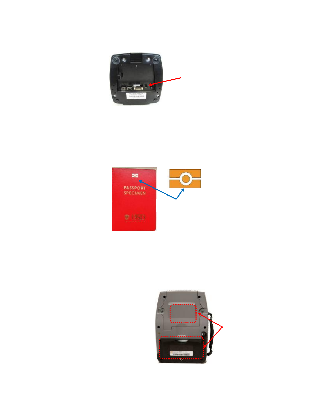
4209-00009-000 EasyRead (DSV3-EP) User’s Manual Rev 0E
6/29/2009
11.2 ActiveSync via the Docking Station
Follow the same procedure as described in section 10.2, except that the USB cable is connected to the
USB client port on the docking station.
USB Client
12 Using the Optical Scanner & Smart Card Reader
12.1 Reading ePassports
The EasyRead is optimized for one-step reading of electronic passports (ePassports) and standard
passports. An ePassport is the same as a traditional passport with the addition of a small integrated circuit
(smart card IC) embedded in the cover. All ePassports are indicated by an internationally recognized logo
(shown below), printed on the front cover.
ePassport logo
The smart card integrated circuit in an ePassport stores:
• The biographical data visually displayed on the data page of the passport
• The passport holder’s photograph stored in digital form
• A unique chip identification number
• A digital signature to protect the stored data from alteration.
• Other optional data as defined by the ICAO standards body.
The EasyRead is equipped with two separate
antennas for reading ePassports, since some
countries have placed the contactless smart card
chip in the front cover of the ePassport, while
other countries have place it in the rear cover.
Having two antennas ensures that the ePassport
smart card IC can be read seamlessly after
scanning the MRZ without having to move the
document away from the optical scanner.
Smart
Card
Antenna
location
Copyright © 2009 by Datastrip, Inc. All rights reserved.
Reproduction in whole or in part is prohibited.
31

4209-00009-000 EasyRead (DSV3-EP) User’s Manual Rev 0E
Place
the passport
6/29/2009
The adjacent figure shows how an ePassport
should be placed in the EasyRead. The passport
should be opened to the data page, and this page
should be placed against the glass platen so it can
be optically scanned and decoded by the terminal.
data page against the
glass platen so it can
be optically scanned.
Once the document is optically scanned, the
system then automatically reads the embedded
smart card integrated circuit in the ePassport*.
* A software application, such as “ICAO
Viewer” should be launched in order to
activate a scan and read process
Shown below are the typical motions for inserting and reading an ePassport. The top sequence of photos
shows the normal operation where the operator can continuously see the LCD screen and observe the
reading operation. The bottom sequence of photos is shown for clarity.
12.2 Contactless Smart Card Reader
The EasyRead can also be used to read a wide range of other ISO
14443 smart card media. Either antenna can be used to read ISO 14443
smart card media. The system will automatically select which antenna
to use. Place and hold the smart card media to be read against the back
of the terminal in the center of the antenna. The adjacent figure shows
a CR80 sized smart card credential centered against the upper antenna.
Smart
Card
Antenna
locations
32
Copyright © 2009 by Datastrip, Inc. All rights reserved.
Reproduction in whole or in part is prohibited.

4209-00009-000 EasyRead (DSV3-EP) User’s Manual Rev 0E
6/29/2009
12.3 Optical Scanner
The EasyRead can also be used to read and decode a wide range of other documents containing optical
symbology. The terminal contains a 1.2 Megapixel image sensor that provides high resolution scanning
(image capture) for decoding numerous optical symbologies. It contains enhanced scanning and decoding
algorithms and can decode all standard 1 dimensional and common 2 dimensional barcodes. There is a
comprehensive SDK that enables rapid custom application development.
The supported optical symbologies are listed below. The entries marked as optional do not ship standard
with the EasyRead (DSV3-EP); however, they are available for purchase.
1D Codes 2D Codes OCR
Code 39 Matrix 2 of 5 PDF417 OCR B: ICAO 9303 Travel Docs
Code 93 Straight 2 of 5 QR Code (optional) OCR B generic (optional)
Code 128 Code 11 Data Matrix (optional) OCR A (optional)
UPC/EAN/JAN Codabar Aztec Code (optional) MICR (optional)
Hong Kong 2 of 5 MSI Plessey Maxicode (optional)
Interleaved 2 of 5 Pharmacode Micro QR Code (optional)
NEC 2 of 5 DataBarTM Codeblock (optional)
Composite Code (optional)
12.3.1 Scanning Instructions
To scan a document, you need to be running some scanning software application such
as ICAO Viewer.exe (for ePassports) or DsCameraScannerEPTest.exe. The
document or credential to be scanned should then be inserted in the document slot and
held against the glass platen. The optical symbology to be read and decoded should be
facing the glass platen. The adjacent figure shows the typical placement of a CR80
(i.e. credit card sized) document.
12.3.2 Scanner Software Interface / Operating Mode
The camera scanning control has several settings that affect the behavior of the scanning operation. There
are two different modes in which the scanner can be configured:
• USB HID (Human Interface Device) as a keyboard emulation mode
• USB Virtual Com mode with Datastrip control API
When the camera scanner is configured for Virtual Com mode, a rich software API is then available to
control the behavior of the device. Virtual Com mode allows more software developer control over the
scanner and more significantly, it enables the reading of binary (non printable) data found often in 2D
barcodes.
USB HID keyboard emulation mode is a more simplistic approach of using the camera scanner. The main
drawback of the HID mode is that it can only decode printable characters. Decoding binary data in this
mode is not possible since the binary data contains ASCII like control characters. It also does not allow
for full configuration of the scanner, for a more methodic scanning operation, for status checking, or for a
watchdog mechanism. To use the scanner in HID mode, a software developer only needs to:
• Invoke some basic initialization / de-initialization methods
• Activate and deactivate a trigger
• Create a focused input window in which the decoded results will be captured and displayed
Copyright © 2009 by Datastrip, Inc. All rights reserved.
Reproduction in whole or in part is prohibited.
33

4209-00009-000 EasyRead (DSV3-EP) User’s Manual Rev 0E
6/29/2009
12.3.2.1 Changing the Operating Mode from Virtual Com Mode to HID Mode
If the scanner is in Virtual Com mode, it can be re-configured for HID mode by using the following steps:
• Launch the DsCamerScannerEPTest.exe application
• Copy and cut out the linear bar code below so it can be inserted and scanned by the terminal.
• To initiate a scan operation, press F2 and hold it down until you hear a confirmation beep
(signifying that the barcode was scanned and decoded).
• You will then hear 2 beeps and the scanner will reboot itself after ~8 seconds. You then hear 3
more beeps.
• You should now be in HID keyboard emulation mode with the default settings, (run
DsCamerScannerHIDTest.exe to verify this.)
FSUSB Keybd Internal
³ 999940
12.3.2.2 Changing the Operating
12.3.2.3 Mode from HID Mode to Virtual Com Mode
If the scanner is in HID mode, it can be re-configured for Virtual Com mode by using the following steps:
• Launch the DsCamerScannerHIDTest.exe application
• Copy and cut out the three bar codes shown below so that they can be inserted and scanned by the
terminal. Scan each of the bar codes sequentially as described below.
• To initiate a scan operation, press F2 and hold it down until you hear a confirmation beep
(signifying that the barcode was scanned and decoded).
§ Scan the top barcode. You should hear 3 beeps.
§ Scan the middle barcode. You should hear 1 beep.
§ Scan the bottom barcode. You should hear 3 beeps.
• The scanner will reboot itself after ~8 seconds. You should then hear 3 more beeps.
• You should now be in Virtual Com mode with the default settings, (run
DsCamerScannerEPTest.exe to verify this.)
34
Copyright © 2009 by Datastrip, Inc. All rights reserved.
Reproduction in whole or in part is prohibited.

4209-00009-000 EasyRead (DSV3-EP) User’s Manual Rev 0E
Insert with
6/29/2009
13 Contact Smart Card Reader Peripheral (Optional)
The Contact Smart Card Reader is an optional module available for the EasyRead and EasyVerify
terminals. It is a factory installed module that is mounted to the bottom of the terminal. The contact
smart card peripheral reads ISO 7816 smart cards.
The docking interface is replicated on the bottom of the peripheral so that the terminal equipped with a
contact smart card peripheral may be used with the docking station. Shown below are the terminals
configured with contact smart card peripherals.
EasyVerify (DSV3-SP) EasyRead (DSV3-EP)
As shown below, the ISO 7816 contact smart card must be inserted with the card’s contacts facing down.
Smart Card Contacts
Card’s Contacts
Facing Down
Copyright © 2009 by Datastrip, Inc. All rights reserved.
35
Reproduction in whole or in part is prohibited.

4209-00009-000 EasyRead (DSV3-EP) User’s Manual Rev 0E
High Density Connector
Slide the Mag Stripe Card Through the Reader:
6/29/2009
14 Magstripe Reader Peripheral (Optional)
The Magstripe Reader is an optional module available for the EasyRead and EasyVerify terminals. It is a
factory installed module that is mounted to the bottom of the terminal. It is housed in the same peripheral
housing as the contact smart card reader (see section 13). The docking interface is replicated on the
bottom of the peripheral so that the terminal equipped with a magstripe peripheral may be used with the
docking station.
The media or credential being read must have the magnetic stripe facing up to be read properly.
Mag Stripe Facing Upward
15 Docking Station
The docking station is an optional peripheral available for the DSV3 mobile terminals and can be adjusted
to for each variant of the mobile terminal. The docking station has the following attributes:
• Wired I/O Access: Provides convenient access to the wired I/O ports on the mobile terminal
when docked.
§ USB 2.0 Host: standard A (x2)
§ USB 2.0 Client: standard B (x1)
§ Ethernet: 10/100 RJ45 (x1)
§ RS-232 DB9 (x1)
• Battery Charging: Supplies power to charge the batteries inside the mobile terminal
• Storage: Provides a convenient place to store the mobile terminal with “grab and go” access.
The docking station mates with the DSV3 terminal via a high
density connector located on the bottom of the terminal. There
are two guide holes on the terminal (and corresponding guide
posts on the docking station) that make it easy to dock and
remove the mobile terminal while providing robust and rugged
connectivity.
Guide Holes
for Docking Station
Copyright © 2009 by Datastrip, Inc. All rights reserved.
36
Reproduction in whole or in part is prohibited.

4209-00009-000 EasyRead (DSV3-EP) User’s Manual Rev 0E
6/29/2009
15.1 Adjusting the Docking Station Backrest
The DSV3 docking station has an adjustable backrest. It is important
to adjust the backrest correctly to ensure proper operation. There is a
forward position (for use with the EasyVerify), and a rear position (for
use with the EasyRead). To change the position of the backrest
support, remove the 2 Philips-head screws in the plastic backrest
support, repositioning the backrest support to the appropriate position,
and then re-tighten the screws.
• Forward Position: This position should be used for
EasyVerify (DSV3-SP).
• Rear Position: This position should be used for EasyRead
(DSV3-EP)
Adjustment Plunger
Screws
Backrest
Support
EasyRead (DSV3-EP)
EasyVerify (DSV3-SP)
Once the backrest is installed in the correct forward or rear position, the adjustment plunger may be
adjusted to accommodate any installed optional peripherals. The height of the adjustment plunger can be
adjusted by pulling it up or pushing it down to best support the specific configuration of the terminal.
There are detents in the mechanism to maintain the selected height. Once the plunger height is adjusted,
place the mobile terminal in the docking station. The adjustment plunger may need to be retracted (turned
counter clockwise) for the unit to fit. With the terminal resting in the docking station, the adjustment
plunger should then be extended (turned clockwise) until it just touches the back of the terminal.
To use the optical scanner on the EasyRead (DSV3-EP) while it is
docked, the adjustment plunger may be removed as shown in the
adjacent picture. The plunger is removed by pulling it upward
until is separates from the backrest support.
Copyright © 2009 by Datastrip, Inc. All rights reserved.
Reproduction in whole or in part is prohibited.
37
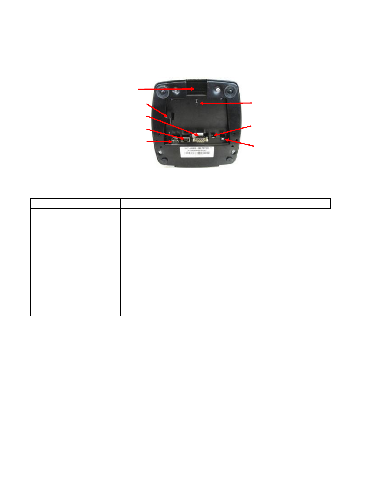
4209-00009-000 EasyRead (DSV3-EP) User’s Manual Rev 0E
Input
6/29/2009
15.2 Docking Station I/O
The docking station provides access to the wired I/O ports of the DSV3 mobile terminal. Shown below is
a photo of the bottom of the docking station depicting the location of each of the I/O connectors. Cables
are normally routed through the cable trough in the back of the docking station. There is a cable tie
anchor point that can be used to secure the cables.
Cable Routing
Trough
Security Cable Loop
RS-232
Cable Tie
Anchor Point
USB Host (x2)
16 Troubleshooting
PROBLEM POSSIBLE REASON AND REMEDY
Unit does not power up
The Power Status LED
turns red when the power
button is held down and
the unit does not power
up.
Ethernet
USB Client
12V Power
• The battery may be completely discharged (or may not be
installed).
• Open the battery access cover and verify that the battery is
properly installed.
• Use the external AC power adapter to operate the unit and to
simultaneously charge the battery.
• Please refer to Section 4.12 “Battery Charging and Replacement”
• This is an indication that the internal battery is very low, and does
not have sufficient charge to run the unit.
• Plug in the AC power adapter to charge the battery AS SOON AS
POSSIBLE.
• Please refer to sections 4.2Error! Reference source not found.
and 4.3 for Power button, LED indicator, and tone operation.
Copyright © 2009 by Datastrip, Inc. All rights reserved.
38
Reproduction in whole or in part is prohibited.

4209-00009-000 EasyRead (DSV3-EP) User’s Manual Rev 0E
6/29/2009
17 Available Parts, Supplies, and Accessories
The following accessories and replacement parts are available for the DSV3 mobile terminals. Please
contact Datastrip or an authorized reseller for a complete list, and for pricing and availability.
1
Stylus (standard or tethered)
2
Shoulder Strap and D-Ring Connection Points
For applications that require over-shoulder carrying of DSV3 devices.
• Ergonomically curved and padded shoulder area, featuring non-slip
material on one side.
• Wide length adjustment range.
3
DSV3 USB 2.0 Active Sync Cable
• For ActiveSync connection to an external server via the USB 2.0 Client Port on the DSV3 terminal.
4
Vehicle Power Charger
ACCESSORIES / SPARE PARTS
5
Internal Memory Upgrade: up to 1 GB of RAM
6
Internal Memory Upgrade: Larger non-volatile Flash memory modules (> 1GB)
7
DS MT SDK (Software Development Kit)
• Provides the software components, samples, and information necessary to develop and deploy large
scale, real world applications.
Copyright © 2009 by Datastrip, Inc. All rights reserved.
Reproduction in whole or in part is prohibited.
39

4209-00009-000 EasyRead (DSV3-EP) User’s Manual Rev 0E
6/29/2009
18 Service & Support
Technical support is available through the following contacts:
Home page and Tech Support: www.datastrip.com
For customers located in North and South America:
Address: Datastrip, Inc.
1285 Drummers Lane Suite 105
Wayne, PA 19087-1572
E-mail: support@datastrip-inc.com
Phone: (610) 594-6130
Fax: (610) 594-6065
Office Hours: 8:30 AM to 5:30 PM EST/EDT
For Customers outside North and South America:
Address: Datastrip Ltd.
1, Thame Park Business Centre
Wenman Road
Thame, Oxfordshire
OX9 3XA
E-mail: uksupport@datastrip.com
Phone: +44 (0) 1844 215668
Fax: +44 (0) 1844 215669
Licensing: +44 (0) 1844 215668
Office Hours: 0900 to 1730 GMT/BST.
+ To return your Datastrip for service, upgrade or repairs, please contact the tech-support department by e-mail
or telephone. An RMA will be issued, and should be clearly marked on the outside of your shipping carton.
Please be certain to provide adequate shipping insurance to safeguard the contents. For international
shipments, please include a declaration of value, or other relevant legal documents that are required for
shipment of this type of equipment.
+ Please use the original shipping carton and packing materials whenever possible.
+ Please ensure you send your package PREPAID or it will not be accepted. Do not ship collect. Datastrip will
return all RMA equipment shipping prepaid as well. Failure to follow this requirement will result in delays.
+ For parts, supplies and accessories, place your order through your authorized Datastrip reseller, or by
contacting Datastrip Limited or Datastrip, Inc.
Datastrip thanks you for purchasing our equipment. If you have any comments, suggestions,
questions, or concerns, we would like to hear from you.
Copyright © 2009 by Datastrip, Inc. All rights reserved.
Reproduction in whole or in part is prohibited.
40
 Loading...