

Page 1
Turbo
DSV2+
User’s Manual
GSA Approved – NIST FIPS 201/SP 800-76 Compliant
Part Number 4207-00008-109
Page 2

DSV2+
Turbo
User’s Manual, Version 1.09
Disclaimer Notice:
Datastrip Inc., Datastrip Ltd., Datastrip Products Inc., and related operating companies (hereafter collectively
referred to as Datastrip) reserve the right to change options, features, specifications, policies, pricing and availability
at any time. Datastrip is not liable for errors or omissions in any product related documentation, specifications or
software. Datastrip makes no claims of suitability for any particular application. Datastrip will not be held liable
for direct or indirect damages or other losses due to loss of data, reliability, or performance issues relating to
Datastrip-provided equipment or software.
Copyright Notice:
No part of this publication may be reproduced, stored in a retrieval system or transmitted in any form or by any
means, electronic, mechanical, photocopying, recording, scanning, or otherwise, except as permitted under section
107 or 108 of the 1976 United States Copyright Act, without the prior written permission from Datastrip. Requests
to Datastrip for permission should be addressed to:
Datastrip Inc.
211 Welsh Pool Road, Suite 100
Exton, PA 19341-1321 USA
Acknowledgements:
• DSV2+
• Windows and WinCE are registered trademarks of Microsoft Corporation.
• All other trademarked or copyrighted names mentioned herein are the property of their respective owners.
Turbo
is a registered trademark of Datastrip.
or
Datastrip Ltd.
Unit 7, Thame Park Business Centre
Wenman Road
Thame, Oxon, OX9 3XA UK
Revision History:
• Version 1.06 – 3/27/07 – Initial release with all features and functions compatible with Wave 6 software
and current product revisions released March 2007
• Version 1.06B – 4/20/07 – Updated Spec sheet and added UPEK Sensor Calibration procedure.
• Version 1.06C – 5/15/07 – Updated Spec sheet, and Appendix A
• Version 1.06D – 9/4/07 – Added Section 4.7.1. Updated Section 5 to specify that scanners should not be
operated on AC power alone. Batteries should always be plugged in for reliable operation. Updated
Sections 7, 9 & 13.
• Version 1.08A – 03/03/08 – Updated Sections 13 and 16 for USB 2.0 Active Sync
• Version 1.08R - 05/02/08 – Updated for regulatory compliance
• Version 1.09 – 07/19/08 – added compliance statement to Section 10
2
Copyright © 2006 by Datastrip, Inc. All rights reserved.
Reproduction in whole or in part is prohibited.
Page 3

DSV2+
Turbo
User Manual, Version 1.09
Table of Contents
1. Overview...............................................................................................................................6
2. Unpacking & Inventory.......................................................................................................7
3. Initial Setup..........................................................................................................................7
4. Hardware Features..............................................................................................................8
4.1 Keypad..........................................................................................................................................8
4.2 Power LED Indications...............................................................................................................8
4.3 LCD, Touch Screen, Fingerprint Sensor & Indicators............................................................9
4.3.1 LCD Display & Touch Screen..............................................................................................................9
4.3.2 Fingerprint Sensor – UPEK Turbo, NIST FIPS 201/SP 800-76 Compliant.........................................9
4.3.3 UPEK Sensor Calibration.....................................................................................................................9
4.3.4 Finger Placement:.................................................................................................................................9
4.3.5 Cleaning the LCD Touch Screen and Fingerprint Sensor.....................................................................9
4.4 I/O Port Access...........................................................................................................................10
4.4.1 External Compact Flash Slot...............................................................................................................10
4.4.2 USB Ports...........................................................................................................................................10
4.4.3 10/100 LAN Ethernet Port..................................................................................................................10
4.4.4 Smart Card Slot...................................................................................................................................10
4.5 Serial Port...................................................................................................................................11
4.5.1 Serial Port Electrical Specifications....................................................................................................11
4.6 Dual Grip Battery Cover...........................................................................................................11
4.7 Digital Still Camera...................................................................................................................11
4.7.1 Digital Still Camera Installation Instructions......................................................................................12
5. Battery Charging and Replacement..................................................................................13
6. Basic Operation..................................................................................................................15
6.1 System Startup Sequence..........................................................................................................15
6.2 Stylus...........................................................................................................................................15
6.3 Touch Screen Adjustments.......................................................................................................15
6.4 Input Panel / Keyboard.............................................................................................................16
6.5 Creating Desktop Shortcuts......................................................................................................16
6.6 Power Management...................................................................................................................16
6.6.1 Power States........................................................................................................................................16
6.6.2 Battery Gauge.....................................................................................................................................17
6.7 Safe Boot Mode..........................................................................................................................18
7. Demo Applications and Utilities........................................................................................18
7.1 Software Version Utility (DsVerify2About.exe)......................................................................18
7.2 Smart Card Reader & Scanner Demo (SuperViewer.exe).....................................................18
7.3 PIV Card and CHUID Verifier (DatastripPIVCard_CHUIDVerifier.exe)..........................21
7.4 Digital Still Camera Demo (DsVerifyStillCameraTest.exe)...................................................23
7.5 Scanner (PA & SW) Test Demo (DsVerifyScanTestAsync.exe)............................................24
3
Copyright © 2006 by Datastrip, Inc. All rights reserved.
Reproduction in whole or in part is prohibited.
Page 4

DSV2+
Turbo
User Manual, Version 1.09
7.6 EPassport ICAO Viewer (ICAO Viewer.exe)..........................................................................26
7.7 Data Capture Enrollment Application (DataCapture,exe)....................................................27
7.8 iClass Card Demo (IClassReadWriteSample.exe)..................................................................28
7.9 IClass Key Loader Utility (DsVerify2KeyLoader.exe)...........................................................28
7.10 Fingerprint Capture Utility (DsVerifyFpCaptureTest.exe)...............................................30
7.11 DsVerify Registry Install Utility (DsVerifyRegInst.exe).....................................................30
7.12 DsVerify Registry Saver Utility (RegistrySaver.exe)..........................................................30
8. Loading Software and Firmware......................................................................................31
8.1 Loading DSV2+ Software Updates...........................................................................................31
8.1.1 DSV2+ Software Update Procedure - Using CF card in external slot................................................31
8.1.2 DSV2+ Software Update Procedure – Using Datastrip FTP site........................................................31
8.2 Loading Scanner Firmware Updates.......................................................................................32
8.3 Loading Smartcard Firmware Updates...................................................................................32
8.4 Loading Digital Still Camera Firmware Updates...................................................................33
8.5 Loading PIC Firmware Updates..............................................................................................33
9. DSV2+
Turbo
-SC Product Specifications - GSA FIPS-201 Compliant...............................34
10. Regulatory Compliance Statement....................................................................................35
11. Fingerprint Algorithms and Support................................................................................36
12. Troubleshooting.................................................................................................................36
13. Available Parts, Supplies, and Accessories.......................................................................37
14. Service & Support..............................................................................................................40
15. Appendix A: Docking Station...........................................................................................41
15.1.1 Adjusting the Docking Station Backrest.............................................................................................41
15.1.2 Dual Grip Tethered Stylus..................................................................................................................41
16. Appendix B: Active Sync...................................................................................................42
16.1 ActiveSync via USB 2.0 Client Port......................................................................................42
16.1.1 Hardware/Software Requirements......................................................................................................42
16.1.2 PC Configuration for USB 2.0 ActiveSync (First Time Only)...........................................................42
16.1.3 Establishing a Connection...................................................................................................................42
16.1.4 Troubleshooting the Connection.........................................................................................................42
16.2 ActiveSync via the Docking Station......................................................................................43
16.2.1 Software/Hardware Requirements and Setup.....................................................................................43
16.2.2 Establishing the Connection................................................................................................................43
16.2.3 Disconnect..........................................................................................................................................43
16.2.4 Troubleshooting the Connection.........................................................................................................43
16.3 ActiveSync via 802.11 CF Adaptor or Bluetooth USB Adaptor.........................................43
16.3.1 Hardware/Software Requirements......................................................................................................43
16.3.2 PC Configuration for 802.11...............................................................................................................43
16.3.3 PC Configuration for Bluetooth..........................................................................................................45
16.3.4 DSV2+ Configuration.........................................................................................................................47
16.3.5 Establishing the Connection................................................................................................................47
16.3.6 Troubleshooting the Connection.........................................................................................................47
4
Copyright © 2006 by Datastrip, Inc. All rights reserved.
Reproduction in whole or in part is prohibited.
Page 5

DSV2+
Turbo
User Manual, Version 1.09
17. Appendix C: Scanner Information...................................................................................48
17.1 Scanner Settings.....................................................................................................................48
17.2 DSV2+
Turbo
-PA Product Specifications.................................................................................51
5
Copyright © 2006 by Datastrip, Inc. All rights reserved.
Reproduction in whole or in part is prohibited.
Page 6
DSV2+
Turbo
User Manual, Version 1.09
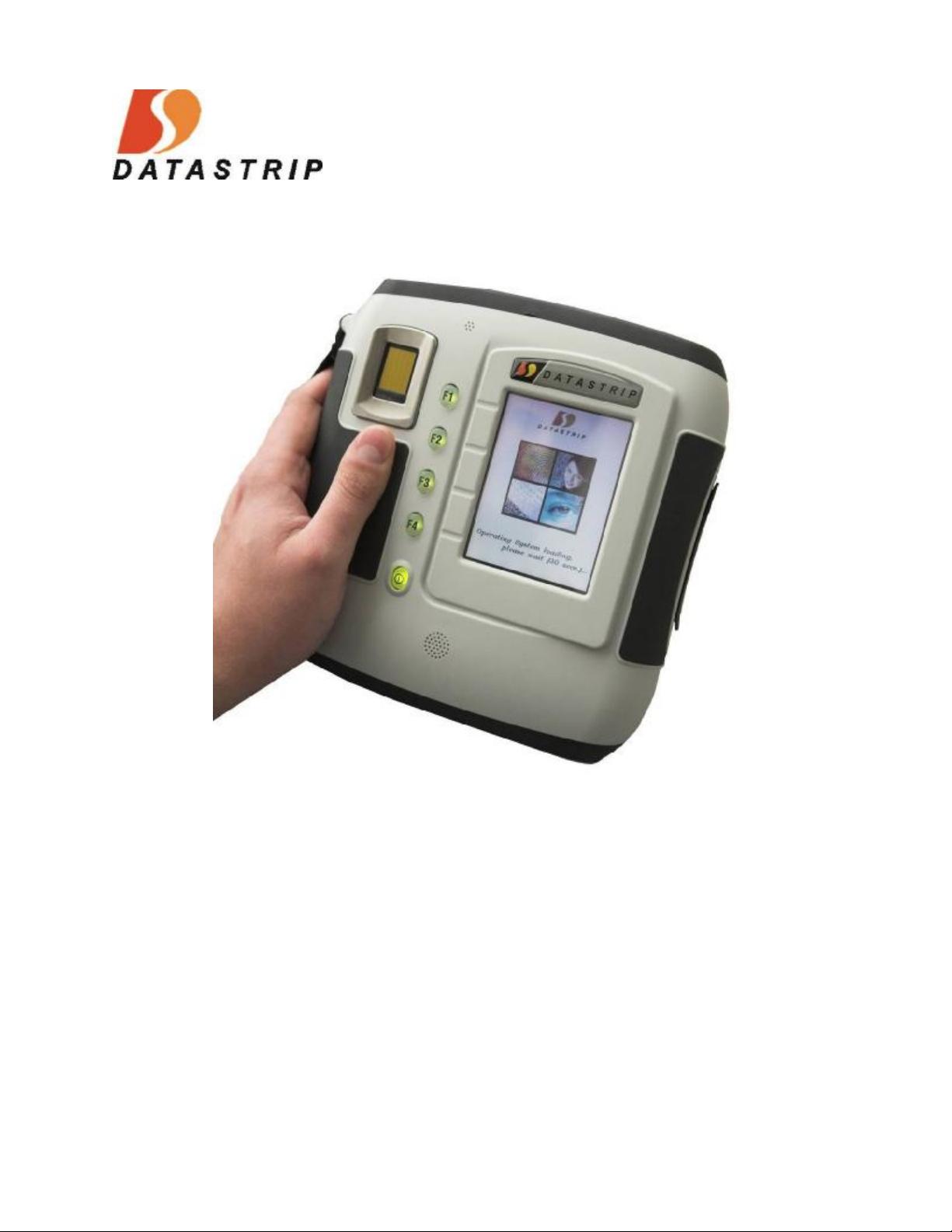
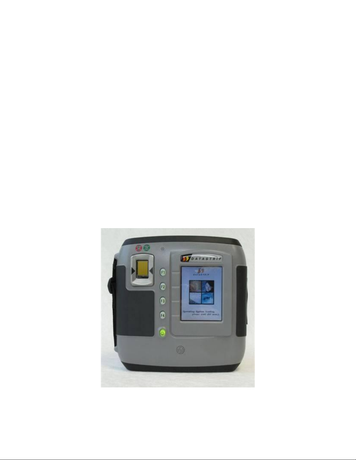
1. Overview
The DSV2+
integrated fingerprint sensor and Smart Card reader with the capability to identify and
authenticate a PIV card by accessing and authenticating the CHUID stored on the cards as
defined by “SP 800-73, Section 1.8.3.”
The Smart Card reader can read both contact style Smart Cards (ISO 7816 compliant) as well as
RF-based contactless Smart Cards (ISO 14443 compliant). The contact and contactless Smart
Cards can be programmed to contain biometric information that can be verified against the
internal fingerprint sensor using 1-to-1 or 1-to-N fingerprint matching algorithms. The
DSV2+
(TWIC), Common Access Card (CAC), and many other ID card scenarios.
The basic DSV2+
Operating System, software utilities, and some demo and sample applications. When the unit is
activated, a standard Windows CE desktop is presented that allows users to launch demonstration
programs. The primary human interface is the touch screen, stylus, and function keys.
The internal fingerprint sensor is an 8-bit, grayscale, solid-state, capacitive-touch device that can
capture fingerprint bitmap images measuring 256 pixels wide by 360 pixels high at 500 dpi.
Images from this sensor can be used for a variety of card holder ID validation purposes,
including extraction, matching, and storage of fingerprint minutia templates.
Turbo
is a GSA Approved, NIST FIPS-201 CHUID, mobile hand-held reader with an
Turbo
is applicable for programs such as USVISIT, Transportation Worker ID Card
Turbo
product comes from the factory with a Windows CE .NET, Version 5.00
Figure 1: DSV2+
Turbo
-SC
6
Copyright © 2006 by Datastrip, Inc. All rights reserved.
Reproduction in whole or in part is prohibited.
Page 7
DSV2+
Turbo
User Manual, Version 1.09
2. Unpacking & Inventory
Depending on the number of terminals ordered, your DSV2+
shipped in a single pack box, a multi pack box or some number of each type. Carefully open the
shipping box(s) and use the following Shipping Box Inventory list to verify the contents.
Shipping Box Inventory:
• DSV2+
Turbo
Smart Card Reader
• Universal (90-240 VAC input) DC power/charging adapter.
• AC power cord for DC power/charging adapter. (Plug depends on country of destination)
• Documentation, including: User Manual (on CD), End User License Agreement, and
Quick-Reference Guide.
Turbo
units and accessories may be
+ Please retain the shipping box in the event you need to return your product for service.
3. Initial Setup
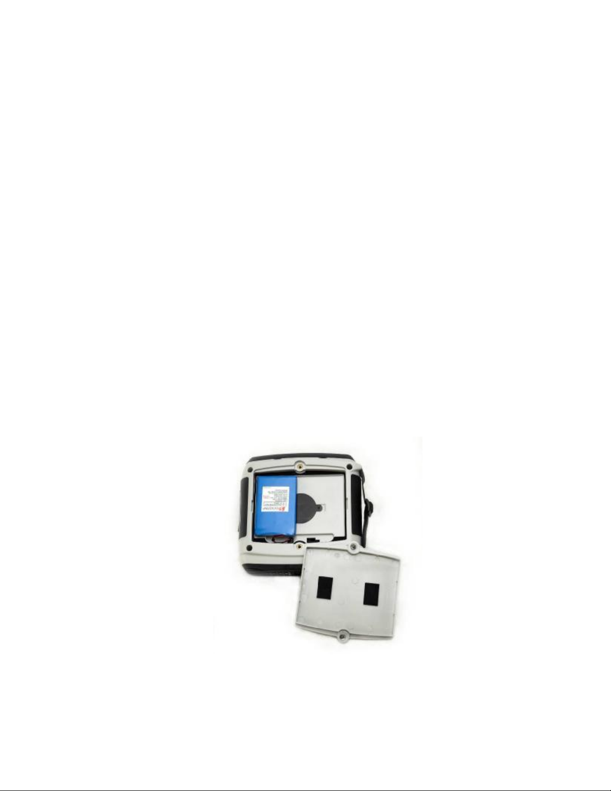
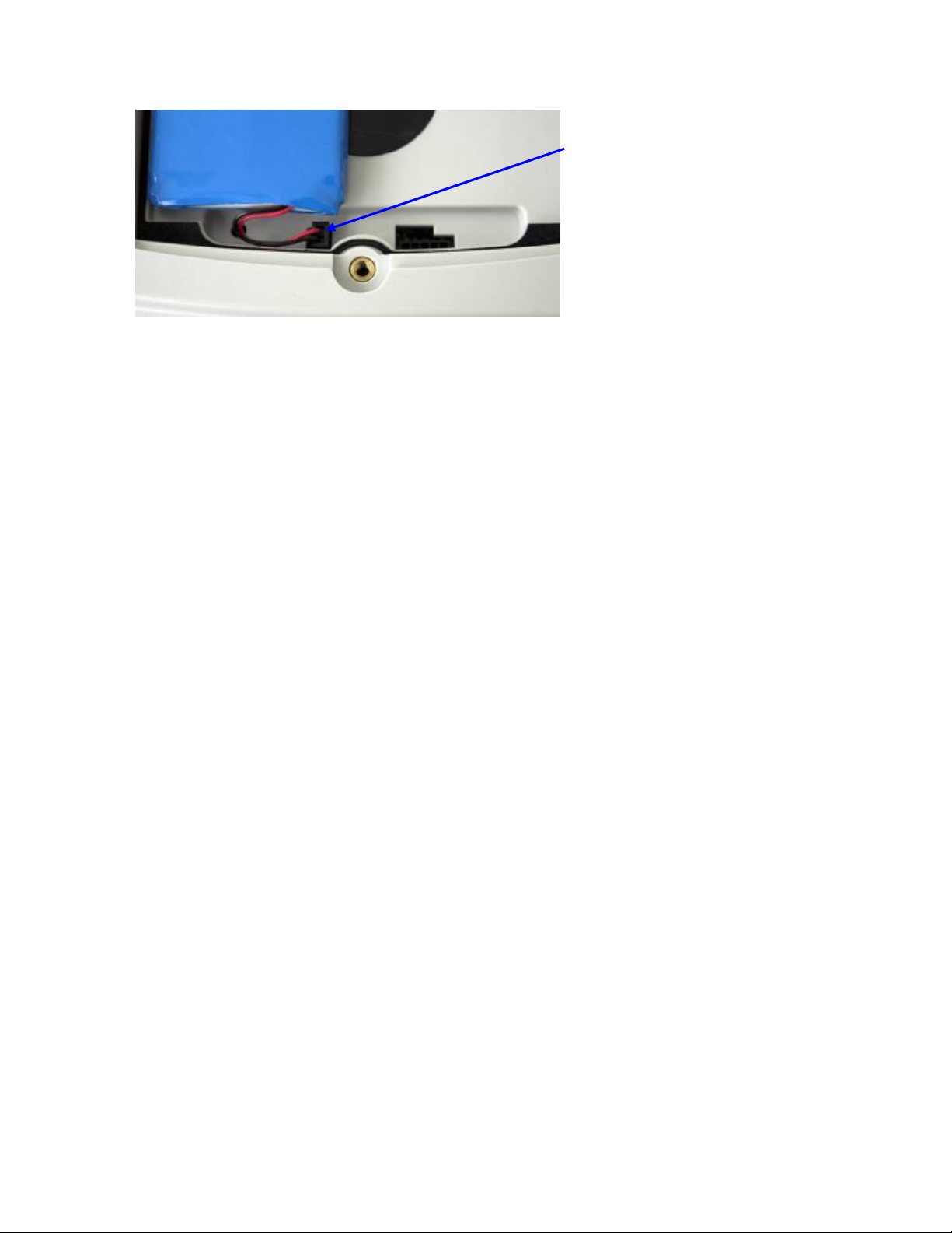
• Each unit is shipped with one Lithium Polymer battery installed, though disconnected.
To connect the battery, you will need to remove the rear battery access cover and plug the
battery connector into the mating connector on the left hand side of the battery
compartment.
• It is recommended that you fully charge the internal battery before use to maximize
operating time before recharging is required. The unit will operate when connected via
the AC adapter regardless of the charge state of the internal battery.
• The DSV2+ contains an integrated charging circuit that allows the batteries to be charged
inside the unit whenever the unit is properly connected to the AC adapter. No external
standalone charger for batteries is required.
+ Please refer to Section 5. 0 “Battery Charging and Replacement”, for additional instructions and
safety information.
7
Copyright © 2006 by Datastrip, Inc. All rights reserved.
Reproduction in whole or in part is prohibited.
Page 8
DSV2+
Turbo
User Manual, Version 1.09
4. Hardware Features
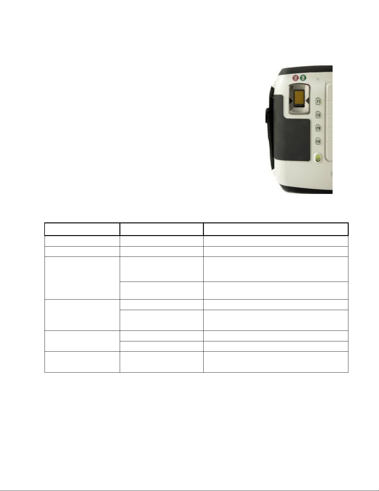
4.1 Keypad
The DSV2+ comes equipped with a backlit, 5-button keypad, shown at
right. The upper four keys are function-keys, and are vertically aligned
along the left side of the LCD display, enabling application software to
position “virtual buttons” appropriately. These keys are initially
programmed as standard “F1” through “F4” keys and are mapped as
cursor (arrow) keys.
Below the four function keys is the power switch. The power switch
has a bi-color (red/green) backlight indicator, which identifies whether
the system is on, charging, or running low on battery power. To turn
the unit on, you must depress and hold the power switch until a single
beep is heard, then immediately release it for an additional two beeps.
Holding the button too long will cause an “error” type beep sound and
the system will not be powered up or down, as the case may be. This
procedure helps to guard against accidental activation or shutdown of
the system.
4.2 Power LED Indications
System State Power-switch LED Comments
Off, not charging
Off, charging
User initiates power-on by
pressing power button.
System Warning: Batteries
very low
Off
Red
Green
Red
Green
Green à Red flash
(90% à 10%)
Green flash
Red flash
Green à Red alternating
(50% à 50%)
Unit is plugged into external power
Release power button after first beep. If power button
is pressed too long it causes an “error” beep tone and
system remains locked “off” until button is released.
Available battery power is too low, causing an “error”
beep tone and unit will not start.
System on, not charging. System on
System on, with the unit plugged into external power
with the AC adapter and batteries charging.
Unit is in the Suspend state and not charging. Suspend mode
Unit is in the Suspend state and batteries are charging.
Batteries are very low and should be charged as soon
as possible
8
Copyright © 2006 by Datastrip, Inc. All rights reserved.
Reproduction in whole or in part is prohibited.
Page 9
DSV2+
Turbo
User Manual, Version 1.09
4.3 LCD, Touch Screen, Fingerprint Sensor & Indicators
4.3.1 LCD Display & Touch Screen
The LCD is a color-TFT (Thin Film Transistor) active-matrix display, and features white-LED
backlighting. There is a resistive touch panel overlay, which should only be operated with the
included stylus to help prevent scratching or other damage.
4.3.2 Fingerprint Sensor – UPEK Turbo, NIST FIPS 201/SP
800-76 Compliant
The DSV2+ UPEK TCS1 fingerprint sensor is an 8-bit, grayscale, solidstate, capacitive-touch device that can capture fingerprint bitmap images
measuring 256 pixels wide by 360 pixels high at 500 dpi. Images from this
sensor can be used for a variety of card holder ID validation purposes,
including extraction, matching, and storage of fingerprint minutia templates.
Datastrip supports fingerprint matching algorithms from a variety of the
industry leading vendors such as: Cogent, Bioscrypt, Identix, Motorola, and
NEC.
4.3.3 UPEK Sensor Calibration
The UPEK sensor is factory calibrated and tested on every DSV2+ terminal, however, if
recalibration is required for whatever reason follow these steps:
• Double tap My Computer and Select Storage Card / DSVII.
• Double tap the PPCalFt41utility and press the “Calibrate” button to re-calibrate the
fingerprint sensor. This process may take up to a minute and then a “green” window
with a number “1” should appear to indicate the sensor was successfully calibrated.
• Double tap the DsVerifyFpCaptureTest application. In the lower right hand corner select
“UPEK” and click “OK”.
• Use the “Scan” button to test the fingerprint image quality.
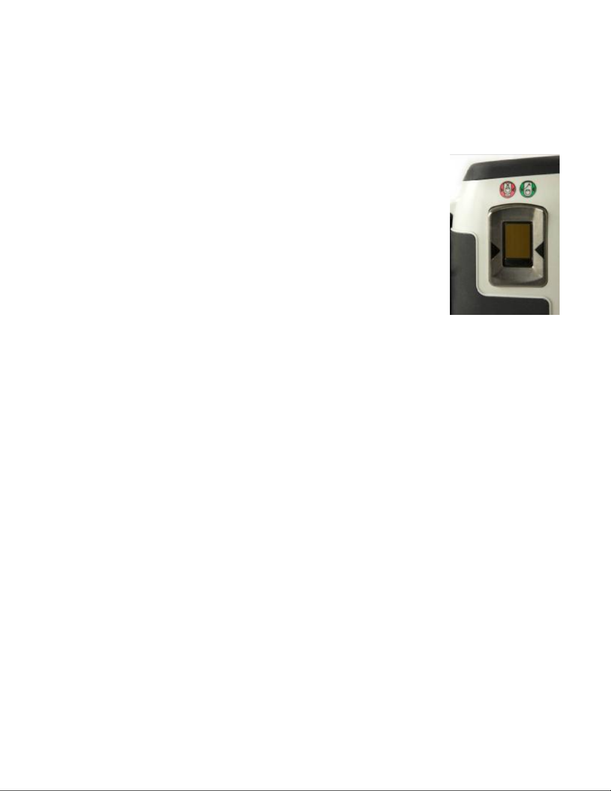
4.3.4 Finger Placement:
It is important to place the finger properly on the sensing area, to enable the DSV2+ to capture
more quickly a good fingerprint image:
• Finger placement icons: These two icons pictorially indicate the correct (green) and
incorrect (red) way to align the cuticle of your finger with the points of the fingerplacement guide arrows.
• Finger placement guide arrows: These arrows should be used as a guide for alignment of
the cuticle part of the finger as described above.
4.3.5 Cleaning the LCD Touch Screen and Fingerprint Sensor
The LCD touch screen and fingerprint sensor require periodic cleaning to remove dirt, oils,
grease, dust, and foreign matter.
• Ensure that the DSV2+ power is OFF and unplugged from any external power source.
• Using standard alcohol wipes, gently wipe the surface of the LCD screen and fingerprint
sensor until it appears clear.
• Allow the cleaning solvent to dry completely before turning the unit on again.
9
Copyright © 2006 by Datastrip, Inc. All rights reserved.
Reproduction in whole or in part is prohibited.
Page 10
DSV2+
Turbo
User Manual, Version 1.09
4.4 I/O Port Access
The top rubber end cap on the DSV2+ snaps open to reveal the I/O ports. To open the top rubber
end cap pull up from the back edge using the two finger indents. The rubber cap is tethered at
two points to prevent it from being lost or misplaced. To reattach the cover, simply press the
cover into place.
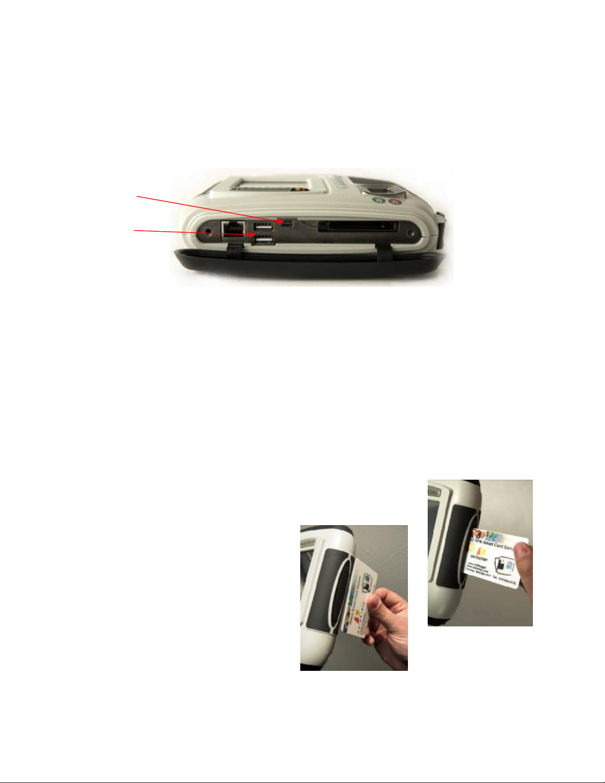
Shown here is the I/O connector panel located on the top of the unit, which includes a 10/100
base-T LAN port, two USB-2.0 host ports, one mini-USB client port, and one external Compact
Flash slot.
USB Client Port
USB Host Ports
4.4.1 External Compact Flash Slot
The DSV2+ has one externally accessible Type-I/II Compact Flash slot. It is compatible with
“ATA-Flash” storage cards, NE-2000-compatible network adapters, and various modem and
serial interface devices.
4.4.2 USB Ports
The DSV2+ supplies two standard USB ports (Ver-2.0), compatible with either low-speed (1.5
Mbps) or full-speed (12 Mbps) devices. These are “host” type ports, compatible with peripheral
devices only (keyboard, mouse, etc.). DO NOT connect this host ports directly to other USB
host devices such as a PC, for these type applications use the mini USB client port (Ver-2.0).
4.4.3 10/100 LAN Ethernet Port
The DSV2+ features an Ethernet LAN port, compatible with 10/100baseT networking standards.
The mating connector is a standard RJ-45. The LAN connector has two integrated LED
indicators: Green for “link activity” and Yellow for “link present”.
4.4.4 Smart Card Slot
The DSV2+ has an integrated Smart Card reader. It is compatible with
Contact-type Smart Cards (ISO 7816, 8-contact style). Cards need to
be inserted with the contacts facing UP (towards the LCD display).
In addition, there is an integrated Contactless
Smart Card transceiver and antenna. The
antenna is positioned in a plane perpendicular
to the LCD screen, on the same side of the
unit as the Smart Card slot. The typical
maximum operating range is 30 mm.
Copyright © 2006 by Datastrip, Inc. All rights reserved.
Reproduction in whole or in part is prohibited.
10
Page 11
DSV2+
Turbo
User Manual, Version 1.09
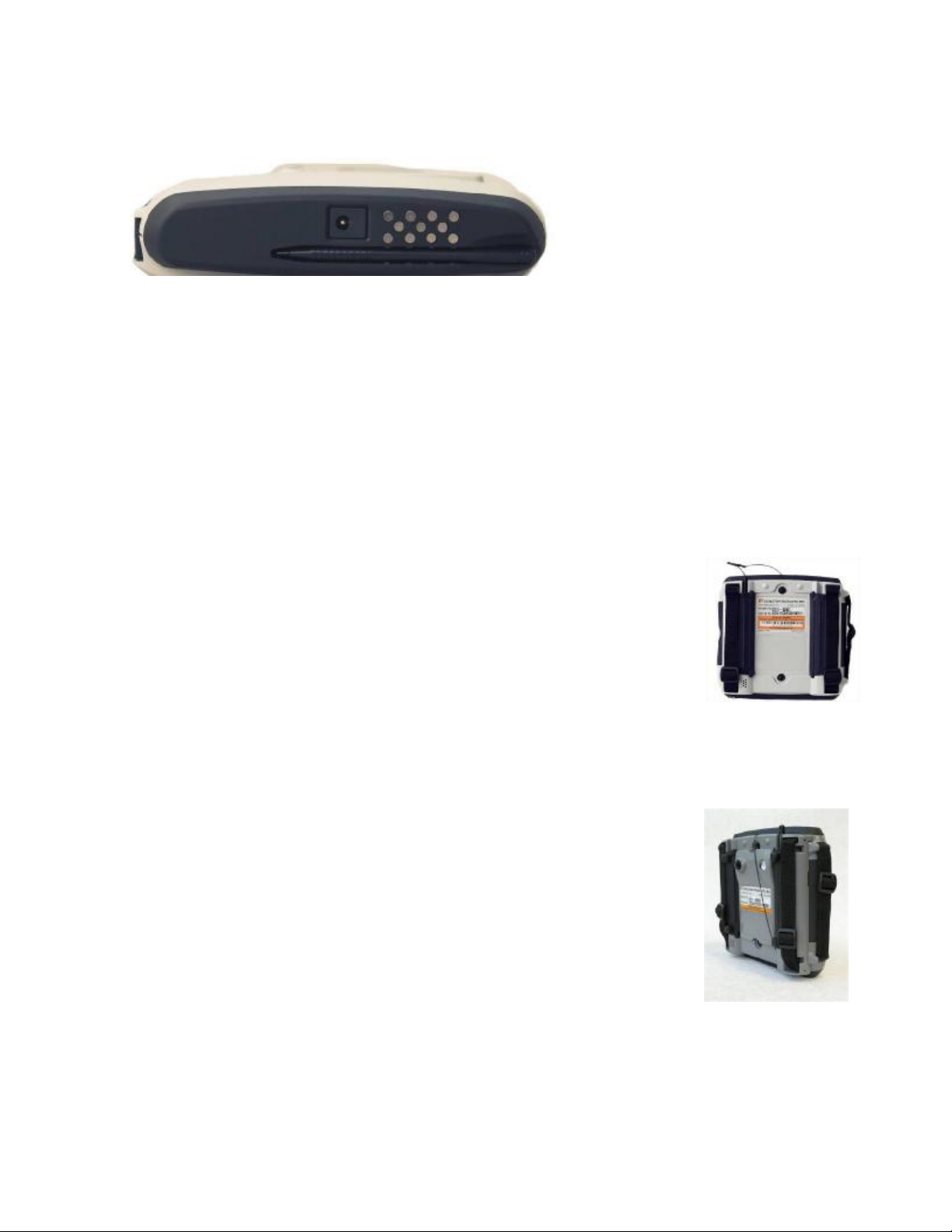
4.5 Serial Port
The DSV2+ contact pins in the bottom endcap provide one external serial port available for
interfacing to a host computer or other external equipment via the Datastrip Docking Station.
4.5.1 Serial Port Electrical Specifications
• Signaling type: RS-232 compatible.
• Output signals: TXD, RTS, DTR.
• Input signals: RXD, CTS, DSR, DCD, RI.
• Interface chip: Maxim MAX3243 or equivalent.
If a specific application requires detailed knowledge of the interface drive capability, latch-up
immunity, safety, or other signaling level information, please refer to manufacturer datasheets
for the interface chips listed above.
4.6 Dual Grip Battery Cover
All models of the DSV2+ can optionally be equipped with a Dual Grip
Battery Cover which provides a more robust handgrip for better control
under harsh conditions. The Dual Grip Battery Cover is an alternative to the
standard battery cover.
4.7 Digital Still Camera
The Digital Still Camera (DSC) is an optional module that is available for
use with any of the DSV2+ models. It is a 3.2 Megapixel camera packaged in a mechanical
module that replaces the standard battery cover of the DSV2+. The DSC is designed for use in a
variety of applications and markets such as facial recognition, law enforcement, mobile
enrollment, and other scenarios.
The Digital Still Camera subsystem is comprised of following 5 major
components:
1. Camera Hardware
2. Camera Firmware
3. Camera Device Driver
4. Camera API/SDK
5. Camera Test/Demo Application (DsVerifyStillCameraTest)
The version of each of the DSC subsystem components can be displayed on
the DSV2+ screen.
• To display the Camera Hardware, Firmware, Device Driver, and SDK versions, select:
“Help->Versions”
• To display the version of the camera test application, select:
“Help->About DsVerifyStillCameraTest”
11
Copyright © 2006 by Datastrip, Inc. All rights reserved.
Reproduction in whole or in part is prohibited.
Page 12
DSV2+
Turbo
User Manual, Version 1.09
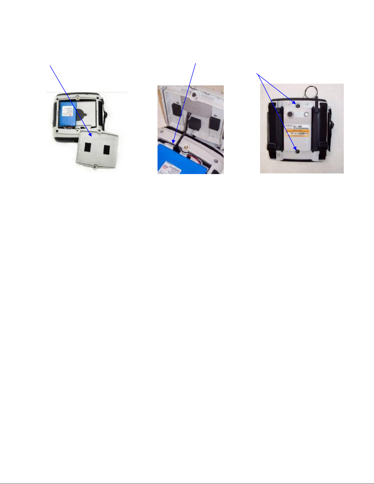
4.7.1 Digital Still Camera Installation Instructions
Step 1 - Remove the DSV2+ battery door cover. Step 2 – Plug the camera cable into the battery
compartment camera connector. Step 3 – Attach the camera housing to the DSV2+ using the
two captive screws.
Step #1 Step #2 Step#3
12
Copyright © 2006 by Datastrip, Inc. All rights reserved.
Reproduction in whole or in part is prohibited.
Page 13

DSV2+
Turbo
User Manual, Version 1.09
5. Battery Charging and Replacement
The standard configuration for the DSV2+ uses one 3000 mAh Lithium Polymer battery pack.
There is also an internal, rechargeable coin cell battery that powers the Real Time Clock for
more than 6 months while the unit is off.
NOTES:
1. Scanners should never be operated on AC power alone. A battery should always be
plugged in for reliable operation.
2. The capacity estimates in the following table are worse case results that reflect continuous
use with all power saving options turned off. The scanner is running 1 scan per minute
continuously. Actual capacity numbers should be much better.
3. The battery capacity (hours of use) can be extended by 50% or more by using the power
savings options such as: System Idle or Suspend. These power settings are user
programmable and details can be found in Section 6.6 Power Management.
4. The charge time is the same whether the battery is charged with the unit “On” or “Off”
5. When a DSV2+ terminal is left on the shelf in the “Off” state the battery will maintain its
charge for over 6 months.
Description SC Capacity
(hours of use)
One 3000 mAh battery 5.5 hours N/A 3 hours
Scanner Capacity
(hours of use)
Charge Time for
fully depleted battery
Comments
Under normal operating conditions, the battery does not need to
be removed. The DSV2+ has an internal charging circuit that
will charge the battery whenever the unit is connected to the
external AC power adapter. The battery may be replaced by
opening the battery-access cover on the rear of the DSV2+.
Before changing the battery turn the DSV2+ power off and
remove the AC adapter. A slotted screwdriver can be used to
operate the fasteners holding the battery compartment cover in
place.
Once the cover is removed, unplug the battery by squeezing the locking tab and pulling up on the
connector at the end of the battery cable. This will unlock the connector, allowing it to be
withdrawn. When replacing the battery, ensure that the battery wiring is tucked in, out of the
way of the mating surfaces for the rear-cover. Replace the battery cover and tighten the fasteners
(do not over-tighten).
13
Copyright © 2006 by Datastrip, Inc. All rights reserved.
Reproduction in whole or in part is prohibited.
Page 14
DSV2+
Turbo
User Manual, Version 1.09
Depress locking tab and pull up to
release the battery cable.
N CAUTION! Use ONLY approved replacement batteries and power adapters as provided by
Datastrip.
N CAUTION! Battery has a risk of FIRE, EXPLOSION, or BURNS. DO NOT: short-circuit the
battery terminals; crush, puncture, disassemble or otherwise damage the battery’s case; operate or
charge at temperatures above 40ºC or store the battery at temperatures above 100ºC; incinerate or
immerse in water.
+ DISPOSAL: Always consult and obey all international, federal, provincial/state, and local hazardous
waste disposal laws. Certain jurisdictions require recycling of this spent product.
14
Copyright © 2006 by Datastrip, Inc. All rights reserved.
Reproduction in whole or in part is prohibited.
Page 15

DSV2+
Turbo
User Manual, Version 1.09
6. Basic Operation
The following sections describe some of the features and functions that are available on the
DSV2+ family of products.
6.1 System Startup Sequence
• To begin operation, press the Power button (located under the Function Keys) and hold
down until one beep is heard. Release the button (two more beeps are heard).
• The unit takes approximately 30 seconds to boot as diagnostic testing is performed. The
display will indicate that the system is booting.
• When the unit powers up, the Windows CE.NET desktop will appear on the display.
6.2 Stylus
The DSV2+ provides a stylus to use with the touch screen for selecting items and entering
information (the unit may also be operated with a standard USB mouse). The DSV2+ stylus is
stored in the bottom end cap of standard units and in the Dual Grip Battery Cover for units that
have that option installed. The following actions are available with the stylus:
• Tap – Lightly touch the screen once with the stylus to open items and select options.
Tapping is equivalent to clicking an item with the mouse on your personnel computer.
• Double-Tap – Lightly touch the screen twice with the stylus to open folders and
applications. Double-Tapping is equivalent to Double-clicking an item with the mouse
on your personnel computer.
• Drag - Hold the stylus on the screen and drag it across the screen to select text and
images. Drag within a list to select multiple items.
• Tap-and-hold - Tap and hold the stylus on an item for a short period until a menu
displays a list of actions available for that item. Tapping and holding is equivalent to
right-clicking your personnel computer mouse button. When you tap and hold, a circle of
red dots appears around the stylus to indicate that the menu will soon pop up. Tap the
action you want to perform on the pop-up menu that appears.
6.3 Touch Screen Adjustments
The touch screen on DSV2+ terminals is calibrated during factory acceptance tests. If you wish
to recalibrate these setting to suit your personnel preferences the following options are available:
• Calibration – If your device isn’t responding properly to your screen taps, you may need
to recalibrate your screen. Go to the Control Panel, select Stylus Properties and under the
“Calibration” tab, click the “Recalibrate” button and follow the on screen instructions.
When you are told to “press enter” to accept the setting, just tap the screen anywhere,
then click the “OK” button.
• Double-Click Sensitivity – Go to the Control Panel and select Stylus Properties. Double–
tap the checkerboard grid to set the double-tap sensitivity for both speed and physical
distance between the taps. Then double tap the icon below the checkerboard to verify
your settings. Click the “OK” button when done.
• Brightness and Contrast – The display brightness and contrast can be adjusted for
different operating environment lighting conditions. Go to the Control Panel, select
Display and under the “Backlight” tab adjust the slider control then click the “OK”
button.
15
Copyright © 2006 by Datastrip, Inc. All rights reserved.
Reproduction in whole or in part is prohibited.
Page 16
DSV2+
Turbo
User Manual, Version 1.09
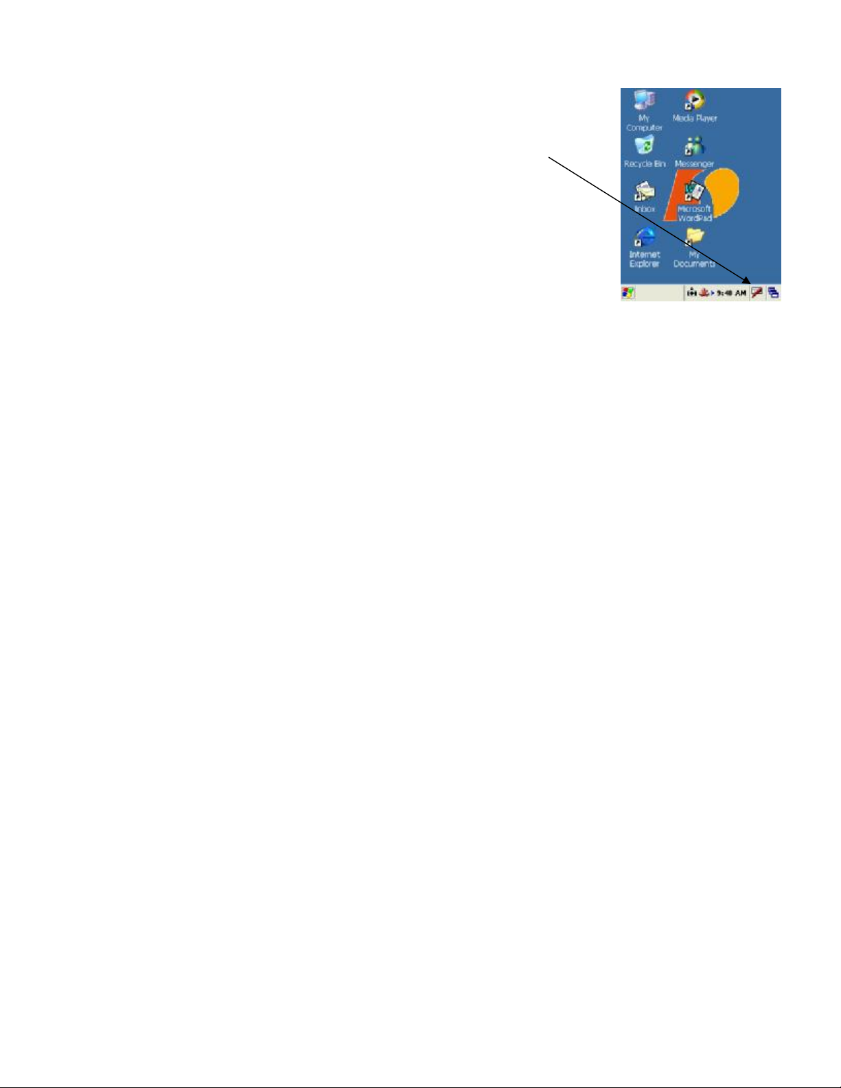
6.4 Input Panel / Keyboard
The input panel (Keyboard) is used to enter alpha-numeric information in
any program on your DSV2+. Tap the Input Panel icon in the bottom right
hand corner of the screen to show the Keyboard or Hide the Input Panel.
6.5 Creating Desktop Shortcuts
Find the application for which you want to create a shortcut. Tap and hold
the stylus on the application until the options menu pops up. Select copy
and go to the directory where you want to put the shortcut. Tap and hold the
stylus until the options menu pops up and select “Paste Shortcut”.
6.6 Power Management
The DSV2+ Power Properties can be configured and monitored by double clicking the Power
icon in the windows Control Panel. The Battery Tab displays the Main battery gauge and the
Schemes Tab allows the user to configure the timeout for each of the Power States defined in the
section below.
6.6.1 Power States
Clicking the power schemes tab allows you to maximize battery life by programming the idle
time for each of the following conditions:
1. Fully On
• Every sub-system is on and operational
2. User Idle
• Touch screen or Function keys haven’t been used for some amount of time (user
configurable).
• Backlight is dimmed to save power, tap the screen and the backlight comes back on.
• All other internal subsystems are on
3. System Idle
• No major background software tasks are running
• Backlight remains dimmed in this state
• All other internal subsystems are on
4. Suspend
Suspend is indicated by flashing power button (flashed red if charging, green if charged
or on AC)
• USB subsystem is turned off
• Display and backlight are turned off
• CF cards are turned off
• Processor is put to sleep
• Tap the screen or give the power button a quick tap to wake up the unit to a fully on
condition
5. Fully Off
• Everything is off
• Push the power button to start the unit and return to a Fully On state
Note: The times configured by the user for each state are cumulative! For example, the time
required for the system to suspend is the sum of the time configured to go to User Idle + the time
to go to System Idle + the time to go to Suspend.
16
Copyright © 2006 by Datastrip, Inc. All rights reserved.
Reproduction in whole or in part is prohibited.
Page 17

DSV2+
Turbo
User Manual, Version 1.09
6.6.2 Battery Gauge
The DSV2+ battery gauge will help you monitor the battery state and the charge held in the
batteries. The battery gauges can be found in the Control Panel under Power Properties.
Clicking the battery tab displays the DSV2+ battery gauge. The gauge displays three battery
states and three battery charging levels.
Battery States – There are three battery states that are displayed above the Main Battery gauge
(left side). The battery states are as follows:
1. Main Battery – Unit is operating on battery power and no external AC adapter is
connected. The Power LED is Green.
2. External - External AC adapter is connected and the battery is fully charged. The
Power LED is Green.
3. Charging – External AC adapter is connected and the battery is charging. The unit
operates normally while simultaneously charging the battery. The power LED is
Green à Red flash
Battery Levels - The three battery levels that are color coded on the battery gauge:
1. Green – Battery charge is Good
2. Yellow – Battery charge is Low
3. Red – Battery charge is Very Low (“Critical”).
As seen in the color coded pie chart below, the three battery levels are not linear. If this were the
gas tank on your car, then “Yellow” would be a quarter of a tank and “Red” would be when the
refuel gas light comes on. When the battery gauge turns “Red”, you should immediately charge
the batteries by connecting the unit to an AC adapter or the unit will automatically shut down
when the voltage level drops below the minimum threshold.
There are four user warnings that occur when the battery level is “Very Low”:
1. The battery gauge turns “Red”
2. The power LED alternately flashes “Red” and “Green”
3. A “Warning” message pops up “Main Batteries Very Low”. This warning will repeat
itself periodically until the condition clears or the unit automatically shuts down.
4. An error beep sounds each time the warning message pops up.
Main & Backup Batteries
Level=Good, State=Charging
Main Battery=No external power
Level=Very Low
Battery Gauge
Very Low
Low
Good
17
Copyright © 2006 by Datastrip, Inc. All rights reserved.
Reproduction in whole or in part is prohibited.
Page 18

DSV2+
Turbo
User Manual, Version 1.09
6.7 Safe Boot Mode
The DSV2+ provides a mechanism that permits the recovery of lost or
damaged Operating System files via a “Safe Boot” mode. This
mechanism is similar to Microsoft Windows Safe Mode that is
available on PCs. If one or more Operating System files are damaged
or inadvertently deleted, when the unit is turned on it will automatically
boot-up into a smaller, limited function version of Windows CE that
will permit the recovery of the files or allow them to be replaced or
overwritten. This permits the unit to be repaired and then subsequently
rebooted using the full version of Windows CE. Safe Boot mode can
also be accessed on demand by holding down the F1 key while turning
on the power to the unit. A special bitmap will appear indicating that
the unit is booting-up in Safe Boot mode.
7. Demo Applications and Utilities
All of the applications listed below except “DsVerify2About” are located in the “\Storage
Card\DSVII” directory. The “DsVerify2About” is a hidden file in the Windows directory.
There are additional demonstration programs available as source code for custom software
development in the Datastrip DSVII SDK (sold separately).
7.1 Software Version Utility (DsVerify2About.exe)
This utility reports the OS Version, the versions of all Datastrip
specific drivers and components, software license settings, the unit
serial number, and the HW Configuration. To run this utility:
• Click Start \ Run
• Click Browse then Double tap the Windows folder
• Scroll over and double tap the application:
DatastripDsVerify2About.exe
• Click “OK”
This version information can be saved to a file by clicking on the
“Send to File” button.
7.2 Smart Card Reader & Scanner Demo (SuperViewer.exe)
This application demonstrates the primary features of the DSV2+ products – reading optical or
smart card media and performing one-to-one fingerprint matching. The types of documents
supported include the following document types or symbology that contains Datastrip-formatted
information:
• ISO 7816 Contact Smart Cards
• ISO 14443 Contactless Smart Cards
The following symbologies are supported on DSV2+ scanner products
• Datastrip2D and 2DSuperscript Two-Dimensional Barcodes
• PDF417
• OCRB
• Linear Barcodes
When this application is launched, the Main Screen is displayed and the unit is ready to scan a
document or read a smart card. The application automatically reads and decodes a submitted
18
Copyright © 2006 by Datastrip, Inc. All rights reserved.
Reproduction in whole or in part is prohibited.
Page 19

DSV2+
Turbo
User Manual, Version 1.09
document and the result is displayed in the Photo, Text, and Fingerprint windows. If the default
icon or text is displayed, the document did not contain that type of data.
If a fingerprint was stored on the document, the application will also perform a one-to-one match
of a fingerprint stored on the document to the fingerprint captured by the on-board fingerprint
sensor. This demonstrates a typical scenario of verifying that a card holder is the same person
whose fingerprint is stored on the document.
Main Screen
Clicking the Datastrip logo will return the user to the Main Screen and will
reset the scanner subsystem (if the unit is a DSV2+ scanner model). On the
Main Screen, a user can perform the following operations:
• Clicking on the ‘toolbox’ button will open the Configuration
Screen.
• Clicking on the ‘OK’ or ‘X’ will exit the application.
• Clicking on the Photo, Text, or Fingerprint windows expands that
window
Configuration Screen
On the Configuration screen, the following operations are available:
• Clicking on the ‘FP Settings’ button will open the fingerprint
threshold setting screen. Refer to the Fingerprint Settings Screen
section below for details.
• Clicking on the ‘Scan Settings’ button will open the scanner
settings screen. Refer to the Scanner Settings Screen section
below for details.
• Clicking on the ‘Timer Settings’ button opens the “Display Timer
Diagnostics” screen. To use this feature you must first “Auto
hide” the windows task bar by clicking “Run” settings/taskbar.
Now check the “Display Timer Diagnostics” box and return to the
main screen. The next document scanned will be timed and
recorded on the bottom line of the display as (Scan: Find: Decode:
Total). e.g. S:5.3 F:0.1 D:0.6 T:6.0.
• Clicking on the ‘Decode Settings’ button will open the Find Decode Settings screen.
Refer to the Find Decode Settings Screen below for details.
• Clicking on the ‘General Settings’ button will open the General Settings screen. To use
the feature check the “Use GUI Buttons” box and return to the Main Screen. The GUI
buttons “Photo”, “Text, and “Fingerprint” will be displayed above the windows.
• Clicking on the “Datastrip” logo button will bring the application back to the Main
Screen.
• Clicking on the ‘Toolbox’ has no effect.
• Clicking on the ‘OK’ or ‘X’ will exit the application.
19
Copyright © 2006 by Datastrip, Inc. All rights reserved.
Reproduction in whole or in part is prohibited.
Page 20

DSV2+
Turbo
User Manual, Version 1.09
Fingerprint Settings Screen
On the Fingerprint Settings screen, a user can configure the thresholds used by
the fingerprint matching algorithms. A higher number tells the system to
require a better match of the fingerprints. Agora, Cogent, and Identix are
different fingerprint algorithms that can be licensed for use on the DSV2+.
• Clicking on the ‘OK’ will save the settings and return the application
to the Configuration Screen.
• Clicking on the ‘Cancel’ or the ‘X’ will abort any changes to the
settings and return the application to the Configuration Screen.
Scanner Settings Screen
On the Scanner Settings screen, a user can configure the Scan Region
(Window size, Scan Intensity for both IR and RGB, resolution and timeout.
The example shown to the right shows the default settings for a DSV2+-PA.
• The scanner parameters can be changed from this screen. For details
on the scanner settings please refer to Appendix B – Section 17.1
Scanner Settings.
• Clicking on the ‘OK’ will save the settings and return the application
to the Configuration Screen.
• Clicking on the ‘Cancel’ or the ‘X’ will abort any changes to the
settings and return the application to the Configuration Screen.
Find Decode Settings Screen
On the Find Decode Settings screen, a user configures the type of optical
symbology the system will look for to decode. Only one symbology at a
time can be selected.
• Select the type of ‘symbol’ that the DSV2+ will Find and Decode
from this screen. The choices are Datastrip, OCRB, PDF417 or
Barcode.
§ Datastrip: Datastrip2D and 2DSuperscript two-dimensional
barcodes
§ OCRB: OCRB text
§ PDF417: PDF417 two-dimensional barcode
§ Barcode: a variety of linear (1 dimensional) barcodes
• Clicking on ‘OK’ will save the settings and return the application to
the Configuration Screen.
• Clicking on the ‘Cancel’ or the ‘X’ will abort any changes to the settings and return the
application to the Configuration Screen.
20
Copyright © 2006 by Datastrip, Inc. All rights reserved.
Reproduction in whole or in part is prohibited.
Page 21

DSV2+
Turbo
User Manual, Version 1.09
7.3 PIV Card and CHUID Verifier (DatastripPIVCard_CHUIDVerifier.exe)
The DSV2+ CHUID software allows an operator to read and authenticate PIV cards as defined
by “SP 800-73, Section 1.8.3”. The application is located in the “\Storage Card\DSVII”
directory in the folder PIVCardApps. Double tap on DatastripPIVCard_CHUIDVerifier and the
Main Menu will open:
The Main Menu:
The main menu is divided into sections: The first section is the
Activity Log window. In this window data sent and retrieved
from the cards is captured for Auditing and diagnostic purposes.
There are 5 Buttons in the Main Menu, as well as 2 radio buttons,
and the OK/Exit controls as seen below
The usage of each button is as follows:
The OK or X buttons - These buttons located in the upper right
corner of the application are used to close or terminate the
application. Clicking either of these buttons will shut down the
application.
The CHUID Button - The CHUID button will perform a number of tests on the card and extract
the CHUID details. Additionally it will check the configuration settings of the program and
determine if the information stored in the card is to be accepted at
this particular station or not. It will also ensure that the card has
not expired.
The process to read/verify the PIV card is as follows:
1. Insert the CHUID card into the unit as shown (Contact
facing up.)
2. Click the CHUID Button.
3. The reader will attempt to parse the data from the PIV
Card and look for the following error conditions.
a. Expired or Abnormal Expiration Data.
b. Non Authorized or incorrect data in the following
fields
i. FASC-N
ii. Agency Code
iii. Organization Code
PIV Card Rejected - Error Conditions:
If either error condition is met the application will display
an error message on top of the Activity Log Window and
notify the operator of a non acceptable PIV card.
21
Copyright © 2006 by Datastrip, Inc. All rights reserved.
Reproduction in whole or in part is prohibited.
Page 22

DSV2+
Turbo
User Manual, Version 1.09
PIV Card Accepted - No Error Conditions:
If there are no errors the display will change to the
CHUID details screen which displays some of the data
elements on the card and no errors will be reported.
This would mean the presented PIV card is acceptable
in this situation.
4. Clicking OK at this point will return you to the
Activity Log Window and the Main Menu
5. Clicking the Clr Button at this point will clear out
all of the data from Activity Log Window.
6. At this point the application is ready to process the
Next PIV Card or move to the Printed info or
Biometric Steps on the existing card.
The Printed Info Button- The Printed Info button will, after
PIN authentication display the stored printed personalization
information on the card. This data can be used as necessary for
auditing, logging, or advanced determination of qualifications.
Tapping the Printed info button will initiate the PIN procedure
and after authentication provide the Printed info Display in the
application
The Biometric Button - This button is used (after pin authentication) to extract the biometric
template from the card. This is for future expansion on the system and allows for custom
integration into a biometric access control system if required by an individual organization.
Tapping the Biometric button will initiate the PIN procedure and
after authentication provide the Biometric Data Display in the
application. This additional functionality is included for systems
integrators to add biometric capabilities at some future point
using the DSVII CHUID SDK.
The Clr Button- Pressing the Clr Button will clear the data from
the Activity Log Window.
The Con Button- The Con or Configure button is used to setup
the configuration for acceptance of a PIV card based on the
following fields:
• FASC-N
• Agency Code
• Organization Code
22
Copyright © 2006 by Datastrip, Inc. All rights reserved.
Reproduction in whole or in part is prohibited.
Page 23

DSV2+
Turbo
User Manual, Version 1.09
The default is that all values are accepted in any of these fields. If the value in any field is blank
the CHUID application accepts any correctly formatted value read from the PIV card as
acceptable. The system integrator or operator can set restrictions on the acceptance by placing
values in these fields. If there is a Value in any of these fields it will be compared against the
data read from the PIV card and if it does not match the card will be rejected. Pressing the Con
button brings up the CHUID Detailed Configuration screen.
To set the configuration an operator does the following actions:
1. Press the Con button
2. Enter the filter data into the appropriate field.
3. Click the OK button.
Card Type Radio Buttons- These buttons are used to select Contact or Contactless Cards to be
read. The contactless setting is there to allow system integrators to add contactless functionality
if required at some point in the future using the CHUID SDK, as well as for diagnostic testing
purposes. The default setting for this application is Contact and a user would have to change
this setting manually to move into contactless mode.
7.4 Digital Still Camera Demo (DsVerifyStillCameraTest.exe)
This application is used in conjunction with the optional Digital Still Camera (DSC) module to
demonstrate the capabilities of the camera subsystem.
After starting the application, the LCD displays preview images which are used to align the
subject in preparation of taking a snapshot. After aligning the subject in the display, pressing F1
will turn on the preview illumination (if selected in the settings), and then pressing F1 a second
time will capture and save the target image. If the preview illumination is not configured,
pressing F1 once will capture and save the target image.
Digital zoom can be controlled via the “Settings” menu or by using the F2 and F3 buttons:
• F3 = X2 digital zoom
• F2 = X1 digital zoom
Snapshots taken and stored by the camera may be viewed on the display via the menu selection
“FILE->Display latest Snapshot”. This will display the last snapshot acquired by the camera.
The user can then navigate to previous and next snapshots via the “FILE->Previous Snapshot”
and “FILE->Next Snapshot” menu selections. Once the user is done reviewing snapshots,
selecting “FILE->Exit snapshot display mode” will return the camera to the previewing state.
It is recommended that an external Compact Flash Storage Card be used for storing snapshots
since there is a limited amount of memory available on the internal Storage Card. All captured
images are stored in 24-bit color depth (full color) BMP files and are stored in the folder \Storage
Card2\DSVII\My Documents if an external Compact Flash card is inserted, or \Storage
Card\DSVII\My Documents if no card is inserted.
To ensure that an adequate amount of internal memory (RAM) is allocated for the camera when
capturing the highest quality images, it is recommended that a minimum amount of internal
memory be used by other applications, and the proper amount of program memory is allocated in
the DSV2+. To set the internal DSV2+ memory allocation for camera use, select “Start”->
“Settings”-> “Control Panel” -> “System”, select the “Memory” tab, then slide the memory
allocation bar to the left until approx. 3456 KB is allocated to storage memory.
23
Copyright © 2006 by Datastrip, Inc. All rights reserved.
Reproduction in whole or in part is prohibited.
Page 24

DSV2+
-
2048 x 1536 (3.2M pixels)
1632 x 1232 (2.0M pixels)
1280 x 1024 (1.3M pixels)
800 x 600 (480K pixels)
640 x 480 (307K pixels)
Automatic, OFF,
10%
10%
Automatic, OFF, Always ON
25% to 100% in increments of
25%
25% to 100% in increments of
25%
OFF, 50 Hz, 60 Hz
ON, OFF
320 x 240, 160 x 120
Normal, Less Sharp, More
Sharp
Automatic, Sunlight, Outdoor
shadow, Fluorescent, Tungsten,
LED
x1, x2
Turbo
User Manual, Version 1.09
Changes to the camera settings can be made via the “Settings” menu selection, and the settings
are stored in the registry and restored the next time the application is run. The Digital Still
Camera settings include:
Setting Selections Available Description of Setting
Brightness
Capture Size
Contrast
Flash Mode
Flash Intensity Still Mode
Flash Intensity Preview
Mode
Flicker Cancellation
Preview Illumination
Mode
Preview Size
Sharpness
White Balance
Zoom
2.0 F-stops to +2.0 F-stops Controls the amounts of light during exposure. The larger the F-stop,
the more bright the image will appear.
Used to select the size of the snapshot image to acquire. Values indicate
the height and width of the image in pixels.
- 100% in increments of
Improves image quality when the camera is used in an environment
Specifies whether or not to use flash illumination during preview mode.
Used to select the size of the preview image displayed on the DSV2+
Used to provide the equivalent of two lenses with different focal
This setting is used to adjust the visual properties of an image that
makes an object in an image distinguishable from other objects and the
background.
Used to specify the flash (illumination) operation when taking snapshot
images.
Controls the intensity of the flash when taking snapshots.
Controls the intensity of the flash when previewing a scene prior to
taking a snapshot.
containing fluorescent lighting. Flickering of fluorescent lighting is
caused by alternating current reversals occurring 50 to 60 times a
second.
screen. Values indicate the height and width of the preview image.
This setting softens or sharpens areas in the image where an edge
changes from one brightness level to another.
Controls the process of removing unrealistic color casts, so objects
which appear white in the scene being captured are rendered white in
the photograph. Specify the setting closest to the environment in which
the snapshot is being taken.
lengths. X1 is normal operation, X2 is the “zoomed” mode.
7.5 Scanner (PA & SW) Test Demo (DsVerifyScanTestAsync.exe)
This application can be used to optically scan and save documents and also allows the decoding
technology to be invoked by the use of a menu. To close the application click File/Exit.
Scanner Screen
• Reset – Resets the scanner subsystem. The message on
the bottom of the display should say “Scanner Idle”.
• Auto Wait for Doc., Scan Image – This is the default
setting.
o After starting the application, the message on the
bottom of the display should say “Waiting for
Scan”
o After scanning a document the message should
read “Scanner Idle w/Image”. You must now
specify to the scanner what type of document you
want to decode and where you want to decode it.
See Decoder Screen options below.
24
Copyright © 2006 by Datastrip, Inc. All rights reserved.
Reproduction in whole or in part is prohibited.
Page 25

DSV2+
Turbo
User Manual, Version 1.09
o When decoding is complete, the scanner will be ready to scan another document and
will again display “Waiting for Scan”.
• Wait for Doc., Scan Image – To operate in this mode, the “Auto Wait for Doc., Scan
Image” option must be unchecked.
o In this non-persistent mode the scanner will scan one document and display
“Scanner Idle w/Image”. The scanner will remain in this state until “Wait for Doc.,
Scan Image” is clicked again and then the message “Waiting for Scan” will be
displayed.
• Upload Image to Memory
This non-persistent option takes the scanned image, uploads it to the Host processor
memory, and shows the image on the display.
• Upload Image to File…
This non-persistent option takes the scanned image and uploads it to a user defined file
name and location.
• Auto Upload Image to File+Auto…
When checked, this option takes the scanned image, uploads it to a user defined file name
and location, and then shows the image on the display.
• Auto Upload Image to Memory
When checked, this option takes the scanned image, uploads it to the Host Processor
memory and shows the image on the display.
• Wait for Doc, Scan, Upload to M…
When doing repetitive operations, this non-persistent option makes things easier by
combining “Wait for Doc., Scan Image” and “Upload Image to Memory”.
• Wait for Doc, Scan, Upload to File…
When doing repetitive operations this non-persistent option makes things easier by
combining “Wait for Doc., Scan Image” and “Upload Image to File”.
• Download Mem. Image to Scanner
This non-persistent option takes an image from the Host Processor memory and downloads
it to the scanner (DSP).
• Download File Image to Scanner…
This non-persistent option takes an image from a file and downloads it to the scanner (DSP).
Decode Screen
• Host Find, Decode …
The Host Processor (SH4) Find and Decode operations are
legacy operations (except for Datastrips).
• Scnr Find, Upload Image to Mem
The image found by the scanner is uploaded to SH4
memory.
• Scnr Find, Decode…
The Scanner (DSP) Find and Decode of the symbology
specified.
• Upload Found Image to Mem
The image found by the Host Processor (SH4) is uploaded
to memory.
25
Copyright © 2006 by Datastrip, Inc. All rights reserved.
Reproduction in whole or in part is prohibited.
Page 26

DSV2+
Turbo
User Manual, Version 1.09
7.6 EPassport ICAO Viewer (ICAO Viewer.exe)
EPassports and other Machine Readable Travel Documents (MRTD) contain, in a standard
format, the holders identification details, including a photograph or digital image, with
mandatory identity elements in a two-line Machine Readable Zone (MRZ) printed in Optical
Character Recognition-B (OCR-B) format at the bottom of the ePassport.
ICAO (International Civil Aviation Organization) has issued a set of guidelines on MRTD which
specifies that these documents should use an RFID chip that can be used to read the individual's
identification details using contactless media. The transmission of data is encrypted by "Basic
Access Control" (BAC) where the key is comprised of data contained on the document itself.
ICAO Viewer Application
The Datastrip ICAO Viewer application is a dialog-based application
created to demonstrate ePassport scanning and decoding. The
ePassport is first scanned to read the Machine Readable Zone (MRZ)
at the bottom of the ePassport. This information contains a key that
can then be used to open the contact-less Smart Card, when
presented to the DSV2+ smartcard reader, and to extract the
biometric information for verification purposes. The ICAO Viewer
application supports JPEG2000 images and is able to read Passports
that utilize passive authentication. The application is located in the
“\Storage Card\DSVII” directory in the folder
“EPassport_ICAOViewer.”
ICAO Figure #1
ICAO Viewer Operation
After opening the application follow the instructions in the dialog box and wait for the Scanner
and ICAO engine to activate. The initialization is complete when the dialog box reads, “Please
Insert Card or Scan Document”. See ICAO Figure#1
After scanning the ePassport the dialog box should indicate “OCR found…”, “Decoding…”. If
the OCR is successfully decoded, the dialog box should now read “OCR verified, present the
scanned document to the reader.” See ICAO Figure #2.
ICAO Figure #2 ICAO Figure #3 ICAO Figure #4
26
Copyright © 2006 by Datastrip, Inc. All rights reserved.
Reproduction in whole or in part is prohibited.
Page 27

DSV2+
Turbo
User Manual, Version 1.09
Once the ePassport is presented to the reader, and the green progress bar indicates data is being
read, see ICAO Figure #3. The Passport must continue to be held against the reader until all the
data has been completely read and the dialog box indicates “Read complete. Remove passport!”,
see ICAO Figure #4. If the dialog box does not indicate “Done” but displays “Please Insert Card
or Scan Document” the key did not verify (could be a bad scan or invalid key). Rescan the
document.
Results
The Document Security Object (SOD), which is a digital signature of the contents of the MRTD
generated by the issuance agency, is stored within the MRTD. It is very important that the
Document Security Object (SOD) is authenticated to prove that the Logical Data Structure
(LDS) is authentic and unaltered.
Passive Authentication (m)
– Proves that the contents of SOD and DGs are authentic and not
changed. It cannot, however, protect against perfect duplications of
the chip or chip substitution.
Active Authentication (o)
– Prevents copying SOD, authenticates chip and proves that chip and
physical passport belong together. It can ensure that the chip is
legitimate and issued by the country claimed
Basic Access Control (o)
– Prevents skimming, eavesdropping, and misuse. The e-Passport
cannot be read by an electronic reader until the machine-readable zone is read first
Results of AA and PA security features are displayed as follows:
AA green : AA successful
AA red : AA failed *
AA orange : AA not required
PA green : PA successful
PA red : PA failed *
PA orange : PA not required
* For AA and/or PA failure pressing F4 displays the errors encountered or relevant messages indicating the reason
of failure. F4 is used to toggle between displaying errors and displaying geographic details of DG1. However, F4
can be used to view errors only when one of these features fails. In all other cases, F4 will navigate you to the
Scanner tab. The errors you come across would be due to unsupported signature algorithms and/or hash algorithms.
7.7 Data Capture Enrollment Application (DataCapture,exe)
The Data Capture enrollment application is used to collect data records that can be stored on a
memory card and transferred to a PC. You Must Have a Digital Still Camera installed for this
application.
New Record: Enter the User Data; Name, Doc #, Date, Location, Type.
Record Composer:
27
Copyright © 2006 by Datastrip, Inc. All rights reserved.
Reproduction in whole or in part is prohibited.
Page 28

DSV2+
Turbo
User Manual, Version 1.09
PHOTO – Clicking on the Photo will open the camera application in preview mode. Press the
F4 key to “Capture” the image. You can then accept the photo or cancel and
recapture a new image.
FINGERPRINT – Clicking on the fingerprint window will open the fingerprint screen. Click
the “Capture” button and place your right index finger on the fingerprint scanner.
You can then accept the fingerprint image or cancel and recapture a new image.
STORE OR CANCEL – Review the record data and “Store” the record or “Cancel” the record.
Stored records will be saved in the DSV2+ folder named “Enrollment_Data”. The
file name structure will be: month:day:year:hour:minute:lastname:doc#.
View Records: From this screen you can scroll through the stored records using the; First,
Previous, Next, and Last buttons. When a record has been selected you can then “Edit” or
“Discard” that record.
Store: Memory Card: The memory card must have a folder named “Enrollment_Data”. When
you click Store: Memory Card, the data from the StorageCard/Enrollment_Data folder will be
copied to the StorageCard2/Enrollment_Data folder.
7.8 iClass Card Demo (IClassReadWriteSample.exe)
The IClassReadWriteSample application is used to enroll and later verify user information on
HID IClass Smart Cards. This sample uses a PC/SC driver developed by Datastrip to operate
with an HID OEM-150 Smart Card reader when it is present in a system. It captures both
fingerprints and photos (using the internal fingerprint imager and Digital Still Camera), collects
some sample demographic information and encodes this data onto 2K IClass Smart Cards for
later verification.
1. Double tap the application called IClassReadWriteSample.exe
a. Two options will be on the screen:
F3 – IClass Reader
F4 – IClass Writer
b. The two buttons allow the writing to and reading from an iClass card.
2. F4 - IClass Writer
a. Select camera type: F3 – FlyCam or F4 – TetraCam
b. F2-FP – press F2 and Place your finger on the fingerprint scanner.
c. F3-Text – press F3 and type Last Name, First Name using the keyboard, then enter.
d. F4-Cam – press F4 to activate the camera preview mode. Press F4 again to capture
photograph.
e. F1-Write – Place iClass card against reader and press F1. Continue to hold card in
position until the message “Transmit Write Success” is displayed.
3. F3 - IClass Reader.
a. Hold the iClass card up to the reader as in previous smartcard tests.
b. While holding the card to the reader press the F3 – Read IClass
button.
c. The message Transmit Read success should appear along with
the message “Place your finger on the scanner.
4. To close the application tap on the “X” in the upper right corner.
7.9 IClass Key Loader Utility (DsVerify2KeyLoader.exe)
28
Copyright © 2006 by Datastrip, Inc. All rights reserved.
Reproduction in whole or in part is prohibited.
Page 29

DSV2+
Turbo
User Manual, Version 1.09
Note: Datastrip loads a default key on new units that allows iClass cards with a default key to be
used. Secure keys can only be obtained through HID or the iClass card distributor can load the
key when you buy iClass cards. After you have obtained a secure key this application allows you
to write the key on iClass cards.
1. Double tap the application DsVerify2KeyLoader.exe.
a. A dialog box will appear with three buttons, Reader, Card and Exit.
2. Loading a key to the Reader.
a. Tap the button labeled “Reader”.
b. A new dialog box will appear.
c. Fill in the edit box labeled key with the Key that is to be loaded into
the reader. The size of every key is 16 alpha numeric characters.
The letters can be lowercase or uppercase.
d. Fill in the edit box labeled Exchng Key. This is the Exchange Key
distributed by HID.
e. Next if you need to change the location that the key is being placed
in the reader, edit the box labeled Rdr Key Loc. This is the location
that the key will be loaded to on the reader.
i. Note: The default value is 3. This is the location that the
DsVerifyIClassDemo looks for its authentication key when
reading and writing to an IClass card.
f. When all the boxes are filled. Tap the button labeled “Load”. This
will attempt to load the key to the reader. Any errors received or if
the loading was successful will be displayed next to the label “Last Result”.
g. To close this dialog tap the “X” in the upper right corner or tap the “Ok” button.
3. Loading a key to a Card.
Note: Loading a key to a card requires two keys to be loaded onto the reader. One needs to
be the authenticating key for the area that the key is being loaded to and the second is the key
that is to be loaded to the card.
a. Tap the button labeled “Card” from the main dialog.
b. A new dialog will appear.
c. Fill in the edit box labeled Authenticating Key Loc with the location where that key
was loaded.
d. Fill in the edit box labeled New Key Loc with the location of
the key to be written to the card, on the reader.
e. Fill in the edit box labeled Card Key Loc with the location on
the card that the key is supposed to be written to.
f. Once the edit boxes are filled with the proper data, tap the
“Load” button. This will attempt to load the key to the
location given on the card. Any error or success will be
shown next to the label “Last Results”.
g. To close the dialog tap the little “X” in the upper right corner
or tap the “Exit” button.
4. To close the application click on the “Exit” button or the “X” in the
upper right corner.
29
Copyright © 2006 by Datastrip, Inc. All rights reserved.
Reproduction in whole or in part is prohibited.
Page 30

DSV2+
Turbo
User Manual, Version 1.09
7.10 Fingerprint Capture Utility (DsVerifyFpCaptureTest.exe)
This application demonstrates the capabilities of the fingerprint image sensor on the DSV2+ and
it provides a means of exercising the fingerprint imaging system. The application has several
buttons that allow a user to Scan to the display or Scan to File. Since this application is provided
as source code in the SDK, it is often used as an example for developers to observe how typical
application software can interface to the fingerprint subsystem. The source code for this
application is provided in the SDK for developer use.
7.11 DsVerify Registry Install Utility (DsVerifyRegInst.exe)
This application registers all of the Datastrip specific components of the DSV2+ that are needed
to read/write Smart Cards, scan documents, operate the Fingerprint sensor, and so forth. It is
typically run after a software update to registers the components in sequence and reports any
errors if it doesn’t succeed. If it finishes successfully, it pops up a message box indicating
“Finished Registration”. It can take up to a minute or two to complete this process.
Internally, this program calls regsvrce.exe to register each ActiveX control so that the interface
presented by the ActiveX control will be available for application use. This is usually followed
by RegistrySaver.exe (or Suspend) to make sure that the altered registry is written to flash
memory for future use. When this application is invoked, it queries the user for the specific
DSV2+ platform type (DSV2+-SC, DSV2+-SW, or DSV2+-PA) and writes the appropriate
platform type information into the registry along with the other registration information.
7.12 DsVerify Registry Saver Utility (RegistrySaver.exe)
This application is used to save the current registry settings to flash memory. This is very useful
after adding applications (or applications components such as ActiveX controls) to DSV2+
products that require some aspect of the behavior to be registered. When any DSV2+ is
powered-on, the saved registry is read and used as part of WinCE startup. Datastrip ActiveX
components are registered (see DsVerifyRegInst application that follows) and then the registry
settings are saved using this application. The registry can also be saved by hitting “Suspend”
function that is located under the Start menu button, but this application is provided to save the
registry to the Storage Card without having to warm-start the unit.
30
Copyright © 2006 by Datastrip, Inc. All rights reserved.
Reproduction in whole or in part is prohibited.
Page 31

DSV2+
Turbo
User Manual, Version 1.09
8. Loading Software and Firmware
8.1 Loading DSV2+ Software Updates
The DsVerify2SoftwareUpdate application permits the user to download software updates from
several source locations are as list below:
• CAB files located on \Storage Card 2, \Storage Card, and USB thumb drives
• CAB files loaded directly from the Datastrip corporate FTP server, (requires a Datastrip
supplied) username and password that accesses a pre-determined account.
• CAB files loaded from user/developer designated FTP servers, given a username and
password to a valid account.
8.1.1 DSV2+ Software Update Procedure - Using CF card in external slot
NOTE: It is recommended that upgrades are done with the unit operating on the AC adapter.
This upgrade process should take approximately 3.5 minutes to complete.
• Power up unit.
• Insert the provided CF Card containing the new OS cab file into the external CF slot.
• When the device is finished booting, double tap My Computer and Select Storage Card /
DSVII.
• Double tap the DsVerify2SoftwareUpdate utility.
• Select Server: Storage Card2 (you must scroll down to make selection)
• Username and Password are not necessary for this procedure
• Select most recent appropriate source file (Ex. Src File: \DSVII_0195_sh4.CAB)
• Click Update (This step will take approximately 2.5 minutes.
• Click Reboot (The registry will be cleared prior to shutdown).
• Power Up unit
• The DSV2+ registration program will automatically open. Select the button for the
device that you are registering (DSVII-SC, DSVII-PA, or DSVII-SW). Select [OK] and
wait. (This process will take from a few seconds).
• Click [Ok] in the “Hurray!” Box when it appears, then close the application window.
• Double tap the RegistrySaver program.
• Double tap My Computer and Select Storage Card / DSVII.
• Double tap the PPCalFt41utility and press the “Calibrate” button to initialize the
fingerprint sensor. This process may take up to a minute and then a “green” window with
a number “1” should appear to indicate the sensor was successfully calibrated.
• Double tap the DsVerifyFpCaptureTest application. In the lower right hand corner select
“UPEK” and click “OK”. DO NOT use the calibrate button on this screen for UPEK,
however you can use the Scan function to test the fingerprint image.
• If you are upgrading a scanner go to Section 8.2
8.1.2 DSV2+ Software Update Procedure – Using Datastrip FTP site
NOTE: It is recommended that upgrades are done with the unit operating on the AC adapter.
This upgrade process should take approximately 13 minutes to complete.
• Power up unit.
• When the device is finished booting double tap My Computer and Select Storage Card /
DSVII.
• Double tap the DsVerify2SoftwareUpdate utility
• Select Server: datastrip.serveftp.net
• Click Connect
31
Copyright © 2006 by Datastrip, Inc. All rights reserved.
Reproduction in whole or in part is prohibited.
Page 32

DSV2+
Turbo
User Manual, Version 1.09
• Select most recent appropriate source file (Ex. Src File: \DSVII_0195_sh4.CAB)
• Click Download and wait for message “Download complete”
• Click Update
• Click Reboot
• Power up unit
• The DSV2+ registration program will automatically open. Select the button for the
device that you are registering (DSVII-SC, DSVII-PA, or DSVII-SW). Select [OK] and
wait. (This process can take from a few seconds to up to 45 seconds).
• Click [Ok] in the “Hurray!” Box when it appears, then close the application window.
• Double tap My Computer and Select Storage Card / DSVII.
• Double tap the RegistrySaver program.
• Double tap the PPCalFt41utility and press the “Calibrate” button to initialize the
fingerprint sensor. This process may take up to a minute and then a “green” window with
a number “1” should appear to indicate the sensor was successfully calibrated.
• Double tap the DsVerifyFpCaptureTest application. In the lower right hand corner select
“UPEK” and click “OK”. DO NOT use the calibrate button on this screen for UPEK,
however you can use the Scan function to test the fingerprint image.
• If you are upgrading a scanner go to Section 8.2
8.2 Loading Scanner Firmware Updates
The DsVerify2ScannerUpdate utility is used to update the DSP firmware in the scanner-based
versions of DSV2+ by installing runtime files of the proper form (.hex extension) which have
been generated by Datastrip.
• Check that the Scanner Firmware provided is compatible for use with the unit by looking
at the DSVII Software Release Notes for the Run-Time software. The version of the
scanner firmware can be checked in the DatastripDsVerify2About application under the
name “ScanVer”.
• In the directory Storage Card/DSVII run the utility DsVerify2ScannerUpdate.exe.
• Using the button marked […]; select by, double clicking, the appropriate scanner runtime
DSP binary file (.hex) that is to be loaded into the scanner sub-system. The latest copy is
usually found in the Storage Card -> DSVII -> DSVII_Scanner_DSP directory. (Ex. Src
File: \DSVII_Scanner_Runtime_Ver_152.Hex)
• Once the appropriate file has been chosen, click the Verify button to validate the format
and checksums for the file.
• Click the Update button to download the file to the scanner DSP engine.
• When the status message indicates “Scanner Update Complete”, Exit the application.
• To confirm the new version has been loaded use the DatastripDsVerify2About.exe
application to check the “ScanVER” entry, which should match the release number of the
(.hex) file that was just loaded.
• Reboot the unit by pressing Power Off button.
8.3 Loading Smartcard Firmware Updates
Smartcard firmware version 5.12 cannot be erased and therefore does not support the update
procedure. Only ScardFw versions 6.32 or later can be updated. Verify the version of your
SCardFw by running the DsVerify2About Utility. The procedure for updating the smartcard
firmware is as follows:
32
Copyright © 2006 by Datastrip, Inc. All rights reserved.
Reproduction in whole or in part is prohibited.
Page 33

DSV2+
Turbo
User Manual, Version 1.09
• In the directory Storage Card/DSVII run the utility “DsVerifyCleanUp” and select the
option “Clear SCM Firmware”. Answer “OK” to the question “Are you REALLY sure”
• Reboot or Suspend as required
• When the device is finished booting double tap My Computer and select Storage Card /
DSVII.
• Open the folder “DSVII_SCM_Firmware”. Verify the new firmware is in the folder:
“SCR331-DI_HW_140_FW_632”
• Double tap the utility “FlashIt”
• Tap the button “Open bin file” and navigate to:
StorageCard/DSVII/DSVII_SCM_Firmware
• Select “SCR331-DI_HW_140_FW_632”and click OK
• Status should read “Binary file is valid.
• Tap the button “Download”
• Reboot to complete update.
8.4 Loading Digital Still Camera Firmware Updates
The DSC Firmware Update Utility is a “stand-alone” program which can be used to update the
camera module’s firmware. The procedure for updating the Digital Still Camera firmware is as
follows:
• In the directory “Storage Card/DSVII” run the utility DSC_Firmware_update.exe.
• The application displays the current version number of the camera firmware and asks the
question “Do you want to update the camera firmware? “
• If you answer “Yes” then browse to the directory “Storage
Card/DSVII/DSVII_DSC_Firmware”, select the latest firmware version and double-click
on it, or select it and hit “OK”.
• Wait for the camera to update its firmware (approx 15 seconds). Note: After the firmware
is updated, the camera illumination LED will blink 10 times.
• Turn the DSV2+ off and then back on to activate the new firmware.
8.5 Loading PIC Firmware Updates
The procedure for updating the PIC firmware is as follows:
• In the directory “Storage Card/DSVII” run the utility DatastripDsVerify2PICUpdate.exe.
• When the dialog box opens that reads “Select valid PIC HEX File” click the small box
and navigate to the directory /Storage Card/DSVII/DSVII_PIC_Firmware
• Double tap the latest release e.g. “PIC_FW_V401.hex” to select it.
• Click the button “Update PIC Firmware”.
• Reboot to complete update.
33
Copyright © 2006 by Datastrip, Inc. All rights reserved.
Reproduction in whole or in part is prohibited.
Page 34

DSV2+
Easy Access to I/O Connectors and
Turbo
User Manual, Version 1.09
9. DSV2+
Turbo
-SC Product Specifications - GSA FIPS-201 Compliant
Physical Characteristics
Dimensions
Weight
Display
Touch Screen
Keypad
Stylus
I/O Panels
Handheld
185 x 185 x 50 mm
(7.3 x 7.3 x 2.0 in)
962 g (2.1 lbs) with 3000 mAh Battery
3.5” Color Reflective TFT LCD
240 (H) x 320 (V) QVGA
LED Backlight
Indoor/Outdoor Viewable
Integrated Resistive Touch Panel
5-Button Backlit Rubber Keypad
Power Button + 4 Function Keys
Integrated Stylus Holder
Battery Compartment
Non-Slip Hand Grips
Adjustable Hand Strap
Hardware/Software
Processor
System Memory
Expandable Memory
Operating System
Interfaces
Audio
Renesas SH4 7760 200 MHz
Floating-Point RISC Processor
64 MB RAM, 16 MB ROM Built-In
256 MB Internal Compact FLASH
Microsoft® Windows
2x USB Host
1x Mini USB Client
1x Serial via Docking Station
1x Ethernet (RJ45)
1x External CF Type I/II
1x Internal CF Type I/II
1x Internal CF Type I/II (System Boot)
0.5 to 4 kHz, 8 Ω, 750 mW
®`
CE .Net V5.0
Environmental Characteristics
Operating Temperature
Storage Temperature
Relative Humidity
Drop Resistance
0° to +40° C (32° to 104° F)
50° C (120° F) or higher at low RH
-20° to +60° C (-4° to 158° F)
< 90% at +40° C Non-condensing
Exceeds MIL-STD 810F
Regulatory Compliance (Core System)
Safety: CE Low Voltage Directive (72/73/EEC)
EMC: CE EMC Directive (89/336/EEC) / (93/68/EEC)
R&TTE: Compliance under EN 300330 & EN 301489-03
NRTL: TÜV Rheinland of North America, Inc.
Regulatory Markings: CE, TÜV NRTL (Canada &US).
EN 60950:2000
EN 55022:1998 & EN 55024:1998
Power Management
External Power
Battery
AC Adapter/Charger
Optional Auto Adapter
11.4 -19 VDC
Rechargeable Li Ion Polymer 7.4 V
3000 mAh Standard Capacity
Integral Protection Circuitry
100-240 VAC
50-60 Hz 30 Watts
Fingerprint Sensor – UPEK TURBO
NIST FIPS 201/SP 800-76 Compliant
Hardware
Resolution
Sensor Area
ESD
Capacitive Solid-State Sensor
256 x 360 pixels
500 DPI, , 8-bit grayscale
12.8 x 18.0 mm
15 KV
Contact Smart Card Interface
Specification
Connector
ISO 7816
8X Landing Style Contacts
100K Min Insertion Cycles
Contactless Smart Card Interface
Specification
Operating Frequency
Operating Range
Security Access Modules
ISO 14443 A/B
13.56 MHz
30 mm
0 or 2
Docking Station
Battery Charging
RS232 Serial Communication
Reliability
Mean Time Between Failure (MTBF)
39,887 Hours
34
Copyright © 2006 by Datastrip, Inc. All rights reserved.
Reproduction in whole or in part is prohibited.
Page 35

DSV2+
Turbo
User Manual, Version 1.09
10. Regulatory Compliance Statement
The DSV2+-SC product is in conformity with the requirements of the Low Voltage Directive
(72/73/EEC) and the EMC directive (89/336/EEC) as amended by (93/68/EEC).
FCC Declaration:
This equipment has been tested and found to comply with the limits for a Class B digital device,
pursuant to part 15 of the FCC Rules. These limits are designed to provide reasonable protection
against harmful interference in a residential installation. This equipment generates, uses, and can
radiate radio frequency energy and, if not installed and used in accordance with the instructions,
may cause harmful interference to radio communications. However, there is no guarantee that
interference will not occur in a particular installation. If this equipment does cause harmful
interference to radio or television reception, which can be determined by turning the equipment
off and on, the user is encouraged to try to correct the interference by one or more of the
following measures:
• Reorient or relocate the receiving antenna.
• Increase the separation between the equipment and the receiver
• Connect the equipment into an outlet on a circuit different from that to which the receiver
is connected.
• Consult the dealer or an experienced radio/TV technician for help.
Note: The DSV2+-SC is fully compliant with the requirements of FCC Part 15 and the EU Low
Voltage Directive (72/73/EEC) for Conducted Emissions only when used with the Datastrip
supplied External Power Supply (DS P/N 3090-01225-02) and External Power Supply AC Line
cord (DS P/N 3008-60163-01).
WARNING: Changes or modification to Datastrip DSVII-turbo-SC not expressly
approved by the party responsible for assuring compliance could void the user's authority
to operate the equipment in a safe or otherwise regulatory compliant manner.
35
Copyright © 2006 by Datastrip, Inc. All rights reserved.
Reproduction in whole or in part is prohibited.
Page 36

DSV2+
Turbo
User Manual, Version 1.09
11. Fingerprint Algorithms and Support
Fingerprint
Matching Vendor
Algorithm Matching
Mode
Support Type Standard Supported / Notes
Identix BioEngine
5.0 or 3.0
Cogent Ver 2.0.0.1 1:1 locally
Bioscrypt BioSDK
Ver 8.1
Agora Ver 1.5 1:1 locally
Motorola 1:1 locally
NEC 1:1 locally
1:1 locally
1:N on host
1:N on host
1:1 locally
1:N on host
1:N on host
1:n locally
1:N on host
1:n locally
1:N on host
12. Troubleshooting
PROBLEM POSSIBLE REASON AND REMEDY
Unit does not power up
Unit generates a single “error”
beep tone, and the power LED
flashes RED once
The battery may be not connected, or may be completely discharged.
ØOpen the battery access cover and verify that the battery is properly installed.
ØUse the external AC power adapter to operate the unit and simultaneously
charge the battery.
Please refer to Section 0 “Battery Charging and Replacement”
ØThis is an indication that the internal battery is very low, and does not have
sufficient charge to run the unit at all.
ØPlug in the AC power adapter to charge the battery AS SOON AS POSSIBLE
Fully Integrated Proprietary
ANSI 378/ANSI 381 - Q3 06
Fully Integrated Proprietary
3rd Party Integrated Proprietary, “User Record Format” ANSI
INCITS 377-2004 Finger Pattern Data
Interchange
Fully Integrated Proprietary
3rd Party Integrated Proprietary
ANSI 378/ANSI 381 - Q3 06
Printrak 1:2000 locally in less than 15 secs
3rd Party Integrated Proprietary
NEC 1:5000 locally in less than 1 second
36
Copyright © 2006 by Datastrip, Inc. All rights reserved.
Reproduction in whole or in part is prohibited.
Page 37

DSV2+
Turbo
User Manual, Version 1.09
13. Available Parts, Supplies, and Accessories
The following replacement parts and supplies are available through the technical-support
contacts, or through your authorized Datastrip reseller. Please contact Datastrip or an authorized
reseller for a complete list of options, accessories, pricing, and availability information.
ACCESSORIES / SPARE PARTS Datastrip P/N
Stylus
D-Ring and Shoulder Strap
For applications that require over-shoulder carrying of
DSV2+ devices. Works with all Models.
Sturdy metal snap-swivels.
Ergonomically curved and padded shoulder area,
featuring non-slip material on one side.
Wide length adjustment range.
DSVXXSS – Shoulder Strap
DSVOSTY
DSVDRING – D-Ring
Dual Grip Battery Cover with Tethered Stylus
More robust handgrip for better control under harsh conditions.
Works with all models.
Digital Still Camera (DSC) Module
3.2M Pixel Color Camera.
Quick point and shoot use.
Seamlessly integrated into dual grip back cover.
Built in flash illumination.
Built in preview illumination.
Auto Exposure.
User configurable operation.
Demo application software included.
Full SDK support.
Docking Stations
Works with all models.
Operates and charges batteries simultaneously while
units are docked.
Serial Cable included for Active Sync connections
Convenient upright position using a two position
backrest.
DSVODGBC
DSVODSC
DSVOACS3 – Power + Serial
DSVOACS1 – Power only
DSV2+ USB 2.0 Active Sync Cable
Provides ActiveSync connection via the USB 2.0 Client Port
DSVII SDK (Software Development Kit)
Provides the software components, samples, and information necessary to develop and
deploy large scale, real world applications.
Datastrip 2D Superscript PC (Software Development Kit)
This kit contains the software that is required in order to generate and decode Datastrips
on PC’s using Win32 based operating systems.
37
Copyright © 2006 by Datastrip, Inc. All rights reserved.
Reproduction in whole or in part is prohibited.
DSVOSCAUSB
DSVIISDK
DSSSDK
Page 38

DSV2+
Turbo
User Manual, Version 1.09
ACCESSORIES / SPARE PARTS Datastrip P/N
Dual-SAM Smart Card Module
ISO 14443 Contactless card support.
ISO 7816 Contact card support.
2 internal security slots for SAM (Security Access Modules).
Internal Memory Upgrade: 512 Meg CF card
DSVODSAM
DSVOMEM512
Internal Memory Upgrade: 1 Gigabyte CF card
Internal Memory Upgrade: 2 Gigabyte CF card
.NET Wrapper License (Oddysey Wrapper):
Used for .NET software development and deployment, such as for Visual Basic and C#.
External Power Supply & Line Cord:
(Universal 90-240 VAC 50/60 Hz input)
External Power Supply Cord:
(Universal 90-240 VAC 50/60 Hz input)
External power supply AC-mains cord: (European):
These cables allow equipment fitted with a figure of 8 power
connector to be plugged into a 2 or 3 pin European mains
power socket (NOT suitable for use in the UK).
DSVOMEM1G
DSVOMEM2G
DSVSOW
DSVOACC
P/N 3090-01225-02
P/N 3008-60163-01
3008-90001-01
External power supply AC-mains cord:
(UK, Ireland, Middle East):
These cables allow equipment fitted with a figure of 8
power connector to be plugged into a UK mains power
socket. They have moulded plugs and are 3 amp fused.
Vehicle Power Charger:
Proximity Card Reader (PROX)
Multi Format ready
Programmable output
Supports HID standard Prox cards
Indala and Motorola also available
Copyright © 2006 by Datastrip, Inc. All rights reserved.
Reproduction in whole or in part is prohibited.
3008-90002-000
DSTPVDCA
DSTPPR
38
Page 39

DSV2+
Turbo
User Manual, Version 1.09
ACCESSORIES / SPARE PARTS Datastrip P/N
Carry Bag
• Outer covering is made from
black ballistic nylon weave,
laminated with padding
material on the inside.
• Zipper access to
insert/remove DSV2+ device.
• Shoulder-strap attachment D-
rings.
• Cover-flap to protect the
front of the device when not in use. Can be “self-stored” when not needed, or
removed when not needed for long periods (scanner models only).
• Stylus pocket.
• Serial & DC power connectors remain accessible for user convenience.
DSVSCCB – DSV2+-SC
DSVPACB - DSV2+-PA
39
Copyright © 2006 by Datastrip, Inc. All rights reserved.
Reproduction in whole or in part is prohibited.
Page 40

DSV2+
Turbo
User Manual, Version 1.09
14. Service & Support
Technical support is available through the following contacts:
Home page and Tech Support: www.datastrip.com
For customers located in North and South America:
Address: Datastrip, Inc.
211 Welsh Pool Road, Suite 100
Exton, PA 19341
E-mail: support@datastrip-inc.com
Phone: (610) 594-6130
Fax: (610) 594-6065
Office Hours: 8:30 AM to 5:30 PM EST/EDT
For Customers outside North and South America:
Address: Datastrip Ltd.
Unit 7, Thame Park Business Centre
Wenman Road
Thame, Oxon
OX9 3XA
E-mail: uksupport@datastrip.com
Phone: +44 (0) 1844 215668
Fax: +44 (0) 1844 215669
Licensing: +44 (0) 1844 215668
Office Hours: 0900 to 1730 GMT/BST.
+ To return your Datastrip for service, upgrade or repairs, please contact the tech-support department
by e-mail or telephone. An RMA will be issued, and should be clearly marked on the outside of your
shipping carton. Please be certain to provide adequate shipping insurance to safeguard the contents.
For international shipments, please include a declaration of value, or other relevant legal documents
that are required for shipment of this type of equipment.
+ Please use the original shipping carton and packing materials whenever possible.
+ Please ensure you send your package PREPAID or it will not be accepted. Do not ship collect.
Datastrip will return all RMA equipment shipping prepaid as well. Failure to follow this
requirement will result in delays.
+ For parts, supplies and accessories, place your order through your authorized Datastrip reseller, or
by contacting Datastrip Limited or Datastrip, Inc.
Datastrip thanks you for purchasing our equipment. If you have any comments, suggestions, questions, or concerns,
we would like to hear from you.
40
Copyright © 2006 by Datastrip, Inc. All rights reserved.
Reproduction in whole or in part is prohibited.
Page 41

DSV2+
Turbo
User Manual, Version 1.09
15. Appendix A: Docking Station
The connector in the bottom endcap of the pins DSV2+
serial port for interfacing to a host computer or other external equipment via the Datastrip
Docking Station.
15.1.1 Adjusting the Docking Station Backrest
The docking station backrest has two positions. It is important to adjust the backrest correctly to
insure proper operation (i.e. serial connection) between the DSV2+ and the docking cradle.
Forward Position: This position should be used for DSV2+
terminals with the standard battery cover. See Figures #1 and #2.
Rear Position: This position should be used for DSV2+
with a Dual Grip Battery Cover, or a Dual Grip Camera Assembly. See Figures #3 & #4.
Turbo
provide external power and one
Turbo
Scanners or DSV2+
Turbo
Scanners or DSV2+
Turbo
Turbo
-SC
-SC terminals
Figure #1–DSV2+ Scanner Figure #2 – DSV2+ SC Figure #3 – Dual Grip Figure #4 – DG Camera
15.1.2 Dual Grip Tethered Stylus
When not in use it is recommended that the Dual Grip tethered stylus cable be stored out of the
way by looping it around the dual grip rubber grips as shown in Figures # 5 and #6.
Figure #5 Figure #6
41
Copyright © 2006 by Datastrip, Inc. All rights reserved.
Reproduction in whole or in part is prohibited.
Page 42

DSV2+
Turbo
User Manual, Version 1.09
16. Appendix B: Active Sync
The flowing sub-sections describe both wired and wireless methods of establishing ActiveSync
communications between the DSV2+ (which runs Win CE) and a PC/Laptop with Windows XP.
Some typical operations you can perform via ActiveSync are:
• Synchronize, backup, and restore information on the DSV2+
• Add and remove files from the DSV2+
• Copy data between the DSV2+ and the PC
• Use the connection to debug programs you develop.
16.1 ActiveSync via USB 2.0 Client Port
16.1.1 Hardware/Software Requirements
The following is required to establish an ActiveSync
connection via the USB 2.0 Client Port:
• ActiveSync version 3.7.1 or later installed on the host PC (Version 4.5 recommended)
• A DSV2+ terminal with USB 2.0 enabled.
• USB 2.0 to Mini B Cable – Datastrip sales code – DSVOSCAUSB.
• Datastrip DSV2+_Turbo_USB Sync Setup utility found on the DSV2+ User Manual CD.
16.1.2 PC Configuration for USB 2.0 ActiveSync (First Time Only)
• Run the “DSV2+_Turbo_USB Sync Setup” utility found on the DSV2+ User Manual CD
• After running the Sync setup you will be prompted to connect your DSV2+ terminal to
the PC. Turn your DSV2+ terminal on and connect it to any one of the host PC USB
ports using the USB 2.0 to Mini B cable. After the DSV2+ terminal has been connected,
Windows will notify you that it has “Found New Hardware”. You will then be asked
“Can Windows Update search for new software?” Answer: NO, not this time.
• The Wizard will then ask how you want to install software. Answer: Install the software
automatically (Recommended).
16.1.3 Establishing a Connection
• Each time you connect the DSV2+ terminal to the host PC you will be asked if you
would like to set up a Partnership. If you will be using this DSV2+ terminal on this PC
regularly then answer “Yes”. If this is a one time use on this PC answer “No”. In either
case you will be connected and can transfer files between the PC and the DSV2+
terminal.
16.1.4 Troubleshooting the Connection
If a connection is not automatically established check the following:
• The DSV2+ will not connect while it is in Suspend mode. Wake the DSV2+ from
Suspend prior to connecting the USB cable.
• Verify that USB 2.0 is enabled on your terminal and that USB via COM3 is selected. Go
to the Control Panel and double click “PC Connection”. On this screen you should see
“USB via COM3”. If not then click “Change Connection”. Click the scroll bar arrow. If
you see the option for “USB on COM3” then select it and click “OK”. Click “OK” again
to close the PC Connection screen. Re-insert your USB cable to get connected. If you did
not see the option for “USB on COM3” your terminal is not USB 2.0 enabled.
42
Copyright © 2006 by Datastrip, Inc. All rights reserved.
Reproduction in whole or in part is prohibited.
Page 43

DSV2+
Turbo
User Manual, Version 1.09
16.2 ActiveSync via the Docking Station
16.2.1 Software/Hardware Requirements and Setup
• ActiveSync version 3.7.1 or later installed on the host PC.
• Docking station, docking station serial cable and Datastrip power adapter.
• Connect the DB9 end of the Docking station serial cable to the PC COM1.
16.2.2 Establishing the Connection
• Turn on the DSV2+ and when it has finished booting, place it in the docking cradle.
• Each time you connect the DSV2+ terminal to the host PC you will be asked if you
would like to set up a Partnership. If you will be using this DSV2+ terminal on this PC
regularly then answer “Yes”. If this is a one time use on this PC answer “No”. In either
case you will be connected and can transfer files between the PC and the DSV2+
terminal.
16.2.3 Disconnect
• Disconnecting the ActiveSync cable or removing the DSV2+ terminal from the docking
cradle will disconnect the session on the PC side, but not on the DSV2+. Manually
disconnect the DSV2+ by clicking on the ActiveSync icon in the system tray and clicking
“Disconnect” or do nothing and the session will timeout after one minute. Both ends of
the connection must be disconnected before you can reconnect the cable and start another
ActiveSync session.
16.2.4 Troubleshooting the Connection
If a connection is not automatically established check the following:
• The DSV2+ will not connect while it is in Suspend mode. Wake the DSV2+ from
Suspend prior to placing it in the docking station.
• Verify that “Serial via COM1” is selected on your terminal. Go to the Control Panel and
double click “PC Connection”. On this screen you should see “Serial via COM1”. If not
then click “Change Connection”. Click the scroll bar arrow. Select “Serial via COM1”
and click “OK”. Click “OK” again to close the PC Connection screen. Re-insert your
DSV2+ into the docking cradle to get connected.
• Place the DSV2+ in the docking cradle. On the PC, open the ActiveSync application and
select “File/Connection Settings”. Then select “Connect”. This will initiate a connection
with the DSV2+ from the PC side.
16.3 ActiveSync via 802.11 CF Adaptor or Bluetooth USB Adaptor
16.3.1 Hardware/Software Requirements
The following materials are required to establish an ActiveSync connection via 802.11:
• A DSV2+ equipped with an 802.11 CF Adaptor or Bluetooth USB adapter.
• A PC connected (wired or wirelessly) to an 802.11 wireless network.
• ActiveSync version 3.7.1 or later installed on the host PC.
• Docking station, docking station serial cable and Datastrip power adapter.
16.3.2 PC Configuration for 802.11
16.4 If connecting the DSV2+ to the host PC via 802.11 for the first
time, start by establishing a wired ActiveSync connection with the
43
Copyright © 2006 by Datastrip, Inc. All rights reserved.
Reproduction in whole or in part is prohibited.
Page 44

DSV2+
Turbo
User Manual, Version 1.09
PC using the procedure described in Section 16.2 “ActiveSync via
USB 2.0 Client Port
16.4.1 Hardware/Software Requirements
The following is required to establish an ActiveSync connection via the USB 2.0 Client Port:
• ActiveSync version 3.7.1 or later installed on the host PC (Version 4.5 recommended)
• A DSV2+ terminal with USB 2.0 enabled.
• USB 2.0 to Mini B Cable – Datastrip sales code – DSVOSCAUSB.
• Datastrip DSV2+_Turbo_USB Sync Setup utility found on the DSV2+ User Manual CD.
16.4.2 PC Configuration for USB 2.0 ActiveSync (First Time Only)
• Run the “DSV2+_Turbo_USB Sync Setup” utility found on the DSV2+ User Manual CD
• After running the Sync setup you will be prompted to connect your DSV2+ terminal to
the PC. Turn your DSV2+ terminal on and connect it to any one of the host PC USB
ports using the USB 2.0 to Mini B cable. After the DSV2+ terminal has been connected,
Windows will notify you that it has “Found New Hardware”. You will then be asked
“Can Windows Update search for new software?” Answer: NO, not this time.
• The Wizard will then ask how you want to install software. Answer: Install the software
automatically (Recommended).
16.4.3 Establishing a Connection
• Each time you connect the DSV2+ terminal to the host PC you will be asked if you
would like to set up a Partnership. If you will be using this DSV2+ terminal on this PC
regularly then answer “Yes”. If this is a one time use on this PC answer “No”. In either
case you will be connected and can transfer files between the PC and the DSV2+
terminal.
16.4.4 Troubleshooting the Connection
If a connection is not automatically established check the following:
• The DSV2+ will not connect while it is in Suspend mode. Wake the DSV2+ from
Suspend prior to connecting the USB cable.
• Verify that USB 2.0 is enabled on your terminal and that USB via COM3 is selected. Go
to the Control Panel and double click “PC Connection”. On this screen you should see
“USB via COM3”. If not then click “Change Connection”. Click the scroll bar arrow. If
you see the option for “USB on COM3” then select it and click “OK”. Click “OK” again
to close the PC Connection screen. Re-insert your USB cable to get connected. If you did
not see the option for “USB on COM3” your terminal is not USB 2.0 enabled.
44
Copyright © 2006 by Datastrip, Inc. All rights reserved.
Reproduction in whole or in part is prohibited.
Page 45

DSV2+
Turbo
User Manual, Version 1.09
• ActiveSync via the Docking Station”. Then remove the DSV2+ from the docking cradle.
• Connect the PC (wired/wireless) to a network which has a wireless router. Test the
connection before proceeding further.
• Configure ActiveSync to support this connection, [FILE] à [CONNECTION
SETTINGS…]
• Select the option “Allow network (Ethernet) and RAS server connection with this
computer”. Uncheck “Allow serial cable or infrared connection to this COM port”.
• Click OK.
16.4.5 PC Configuration for Bluetooth
16.5 If connecting the DSV2+ to the host PC via 802.11 for the first
time, start by establishing a wired ActiveSync connection with the
PC using the procedure described in Section 16.2 ActiveSync via
USB 2.0 Client Port
16.5.1 Hardware/Software Requirements
The following is required to establish an ActiveSync connection via the USB 2.0 Client Port:
• ActiveSync version 3.7.1 or later installed on the host PC (Version 4.5 recommended)
• A DSV2+ terminal with USB 2.0 enabled.
• USB 2.0 to Mini B Cable – Datastrip sales code – DSVOSCAUSB.
• Datastrip DSV2+_Turbo_USB Sync Setup utility found on the DSV2+ User Manual CD.
16.5.2 PC Configuration for USB 2.0 ActiveSync (First Time Only)
• Run the “DSV2+_Turbo_USB Sync Setup” utility found on the DSV2+ User Manual CD
• After running the Sync setup you will be prompted to connect your DSV2+ terminal to
the PC. Turn your DSV2+ terminal on and connect it to any one of the host PC USB
ports using the USB 2.0 to Mini B cable. After the DSV2+ terminal has been connected,
Windows will notify you that it has “Found New Hardware”. You will then be asked
“Can Windows Update search for new software?” Answer: NO, not this time.
• The Wizard will then ask how you want to install software. Answer: Install the software
automatically (Recommended).
16.5.3 Establishing a Connection
• Each time you connect the DSV2+ terminal to the host PC you will be asked if you
would like to set up a Partnership. If you will be using this DSV2+ terminal on this PC
regularly then answer “Yes”. If this is a one time use on this PC answer “No”. In either
case you will be connected and can transfer files between the PC and the DSV2+
terminal.
16.5.4 Troubleshooting the Connection
If a connection is not automatically established check the following:
• The DSV2+ will not connect while it is in Suspend mode. Wake the DSV2+ from
Suspend prior to connecting the USB cable.
45
Copyright © 2006 by Datastrip, Inc. All rights reserved.
Reproduction in whole or in part is prohibited.
Page 46

DSV2+
Turbo
User Manual, Version 1.09
• Verify that USB 2.0 is enabled on your terminal and that USB via COM3 is selected. Go
to the Control Panel and double click “PC Connection”. On this screen you should see
“USB via COM3”. If not then click “Change Connection”. Click the scroll bar arrow. If
you see the option for “USB on COM3” then select it and click “OK”. Click “OK” again
to close the PC Connection screen. Re-insert your USB cable to get connected. If you did
not see the option for “USB on COM3” your terminal is not USB 2.0 enabled.
46
Copyright © 2006 by Datastrip, Inc. All rights reserved.
Reproduction in whole or in part is prohibited.
Page 47

DSV2+
Turbo
User Manual, Version 1.09
• ActiveSync via the Docking Station”. Then remove the DSV2+ from the docking station.
• Ensure that the Bluetooth adaptor has been plugged in to the PC. The Bluetooth icon is
blue with a white symbol.
• In the [CONTROL PANEL] open [BLUETOOTH DEVICES]. Add an “Incoming”
COM port and activate “turn on discovery”. Also ensure that Bluetooth is NOT set for
any security or encryption.
• Note which COM port the PC Bluetooth operates on. This will be a virtual port -
incoming port, for example COM5.
• In the ActiveSync application, configure the serial port for Bluetooth from [FILE] à
[CONNECTION SETTINGS…]
• Check “Allow serial cable or infrared connection to this COM port”. From the drop-
down list, select the COM port obtained above.
• Uncheck the other two “Allow…” check boxes.
• Click OK.
16.5.5 DSV2+ Configuration
• Switch on the DSV2+ and configure the internal/external 802.11 CF Adaptor or
Bluetooth to connect to the wireless router to which the PC is connected. If the DSV2+
finds an 802.11 adapter or Bluetooth adapter, you will find an icon (screens or pipes) in
the notification area with the Ethernet icon.
• Double-click the icon. Configure the 802.11 adaptor on this screen and browse through
to the tab [WIRELESS INFORMATION].
• Double-click your wireless network. Configure the adaptor as necessary to connect to the
router. Click OK. Note that your network name in the list will display “(preferred)”.
• Select your network from the list again and click Connect. The status will change to
“Connected to YourNetworkName” and the icon in the notification area will glow.
• Press “Power Button” momentarily and after the LED extinguishes, press momentarily
again. This saves the registry changes. Alternately, [STORAGE CARD] à [DSV2+] à
[SAVEREG.EXE]. Click OK to save registry changes.
16.5.6 Establishing the Connection
• Switch on the DSV2+. Once the DSV2+ has booted up, place it in the docking cradle.
• A connection should be established as soon as you place the DSV2 in the docking station.
16.5.7 Troubleshooting the Connection
If a connection is not automatically established check the following:
• See Section 16.2.4 “Disconnect
• Disconnecting the ActiveSync cable or removing the DSV2+ terminal from the docking
cradle will disconnect the session on the PC side, but not on the DSV2+. Manually
disconnect the DSV2+ by clicking on the ActiveSync icon in the system tray and clicking
“Disconnect” or do nothing and the session will timeout after one minute. Both ends of
the connection must be disconnected before you can reconnect the cable and start another
ActiveSync session.
• Troubleshooting the Connection”
47
Copyright © 2006 by Datastrip, Inc. All rights reserved.
Reproduction in whole or in part is prohibited.
Page 48

DSV2+
Turbo
User Manual, Version 1.09
17. Appendix C: Scanner Information
The DSV2+ optical scanner products (DSV2+
functionality of the DSV2+
Turbo
-SC and additionally provide the ability to optically scan and
Turbo
-SW and DSV2+
decode a variety of documents including passports, travel visa, drivers licenses, National ID
cards, and a wide variety of other ID cards. The optical symbologies processed and decoded by
the DSV2+ scanners include:
Two-Dimensional
Linear Barcodes Character
Barcodes
Datastrip2D Code39 OCRB
2DSuperscript UPCA
PDF417 UPCE
EAN13
EAN8
I2 of 5
Code 128
Codabar
2 and 5 digit supplementals
for EAN and UPC codes
The PA and SW scanners differ only in their ability to scan different document widths as shown
in the table below. Aside from this, they are architecturally and functionally the same.
Scan Window Size
DSV2+
DSV2+
Turbo
Turbo
-PA
-SW
3.36” (81 mm)
1.15” (27 mm)
The SW and PA both scan documents at up to 600 dpi in 8-bit grayscale with a user selectable
illumination source of Near IR or RGB / Visible light. The default configuration of the scanner
is to use RGB / Visible light illumination since this setting works for a large percentage of
document types. However, many travel documents have a background printed in RGB and
OCBR symbology printed with carbon based ink which resonates in near IR wavelength;
therefore, it is recommended that the scanner be configured for IR illumination (see below) when
processing these document types.
Turbo
-PA ) contain all of the
Recognition
17.1 Scanner Settings
Listed below are the user configurable scanner settings. These
configuration options can be adjusted programmatically by calling API
functions or by using a Datastrip supplied sample application such as
DsVerifyScanTestAsync.exe which is located in the \Storage
Card\DSVII directory.
RGB Scanner Settings:
From the menu select “Scanner” and then select “Scanner settings…”
• Make sure the “IR” box is unchecked
• Set Intensity=50%.
• Leave all the other settings as default
48
Copyright © 2006 by Datastrip, Inc. All rights reserved.
Reproduction in whole or in part is prohibited.
Page 49

DSV2+
TOP
LEFT
Turbo
User Manual, Version 1.09
IR Scanner Settings:
From the menu select “Scanner” and then select “Scanner settings…”
• Make sure the “IR” box is checked
• Set Intensity=35%.
• Leave all the other settings as default
Scan Region:
Left and Right: The parameters that define the length of the symbology that will be scanned on a
document. Left defines how far from the beginning of a document that the symbology starts.
Right defines how far from the beginning of a document that the symbology ends.
Top and Bottom: The parameters that define the width of symbology that will be scanned on a
document. Top defines the outside edge of the card guide and Bottom defines in the inside edge
of the card guide.
The default scan regions are set to the maximum length and width as follows:
DSV2+
Turbo
-PA DSV2+
Turbo
-SW
Left = 0 inches Left = 0 inches
Right = 5 inches Right = 5 inches
Top = 0 inches Top = 0 inches
Bottom = 3.36 inches Bottom = 1.14667 inches
Example:
BOTTOM
3.36”
0
0
5”
RIGHT
Resolution:
When scanning OCRB documents the scanner resolution can be set for 200, 300 or 600 DPI.
When scanning Datastrip symbologies the resolution should be set for 600 DPI.
49
Copyright © 2006 by Datastrip, Inc. All rights reserved.
Reproduction in whole or in part is prohibited.
Page 50

DSV2+
Turbo
User Manual, Version 1.09
Compress:
The compress option should be used to do decoding on the Host processor or to do document
archiving. The option will compress .BMP files to .JPEG making the file size smaller and the
internal file transfer faster.
Calibrate:
The default for this option is “Normalize” (calibrate box unchecked).
In Normalize mode the DSP looks for the darkest and lightest spots on the whole image and then
balances the image.
In Calibrate mode the DSP for the darkest and lightest spots on a row by row basis. This mode is
slower but sometimes helpful for problematic (“noisy”) images.
Wait Timeout:
The Wait Timeout is the time, in seconds, that the scanner subsystem will wait for a document to
be scanned before restarting the scanner subsystem.
50
Copyright © 2006 by Datastrip, Inc. All rights reserved.
Reproduction in whole or in part is prohibited.
Page 51

DSV2+
Easy Access to I/O Connectors and
Turbo
User Manual, Version 1.09
17.2 DSV2+
Turbo
-PA Product Specifications
Physical Characteristics
Dimensions
Weight
Scanning Subsystem
Display
Touch Screen
Keypad
Stylus
I/O Panels
Handheld
185 x 274 x 50 mm
(7.3 x 10.8 x 2.0 in)
1.6 kg (3.5 lbs) with standard battery
Scan Window: 81mm
600 dpi Contact Image Sensor
RGB and IR Illumination
DSP (TI) based for high performance
3.5” Color Reflective TFT LCD
240 (H) x 320 (V) QVGA
LED Backlight
Indoor/Outdoor Viewable
Integrated Resistive Touch Panel
5-Button Backlit Rubber Keypad
Power Button + 4 Function Keys
Integrated Stylus Holder
Battery Compartment
Non-Slip Hand Grips
Adjustable Hand Strap
Hardware/Software
Processor
System Memory
Expandable Memory
Operating System
Interfaces
Audio
Renesas SH-4 7760 200 MHz
Floating-point RISC Processor
64 MB RAM, 16 MB ROM Built-In
256 MB Internal Compact FLASH
Microsoft® Windows
2x USB Host
1x Mini USB Client
1x Serial via Docking Station
1x Ethernet (RJ45)
1x External CF Type I/II
1x Internal CF Type I/II
1x Internal CF Type I/II (System Boot)
0.5 to 4 kHz, 8 Ω, 750 mW
®`
CE .Net V5.0
Environmental Characteristics
Operating Temperature
Storage Temperature
Relative Humidity
Drop Resistance
0° to +40° C (32° to 104° F)
50° C (120° F) or higher at low RH
-20° to +60° C (-4° to 158° F)
< 90% at +40° C Non-condensing
Exceeds MIL-STD 810F
Regulatory Compliance (Core System)
Safety: CE Low Voltage Directive (72/73/EEC)
EMC: CE EMC Directive (89/336/EEC) / (93/68/EEC)
R&TTE: Compliance under EN 300330 & EN 301489-03
NRTL: TÜV Rheinland of North America, Inc.
FCC Declaration:
This device complies with part 15 of FCC Rules. Operation is subject to the
following two conditions: (1) this device may not cause harmful interference,
and (2) this device must accept any interference received, including
interference that may cause undesired operation.
Regulatory Markings: CE, TÜV NRTL (Canada &US)
EN 60950:2000
EN 55022:1998 & EN 55024:1998
Power Management
External Power
Battery
Backup Power
AC Adapter/Charger
Optional Auto Adapter
11.4 -19 VDC
Rechargeable Li Ion Polymer 7.4 V
3000 mAh Standard Capacity
Integral Protection Circuitry
Rechargeable Lithium Internal Cell
100-240 VAC
50-60 Hz 30 Watts
Fingerprint Sensor – UPEK TURBO
NIST FIPS 201/SP 800-76 Compliant
Hardware
Resolution
Sensor Area
ESD
Capacitive Solid-State Sensor
256 x 360 pixels
500 DPI, , 8-bit grayscale
12.8 x 18.0 mm
15 KV
Contact Smart Card Interface
Specification
Connector
ISO 7816
8X Landing Style Contacts
100K Min Insertion Cycles
Contactless Smart Card Interface
Specification
Operating Frequency
Operating Range
Security Access Modules
ISO 14443 A/B
13.56 MHz
30 mm
0 or 2
Docking Station
Battery Charging
RS232 Serial Communication
Reliability
Mean Time Between Failure (MTBF)
39,887 Hours
51
Copyright © 2006 by Datastrip, Inc. All rights reserved.
Reproduction in whole or in part is prohibited.
 Loading...