

Datas Technology Node 4000, Host IMS-4000, D-100 Series Installation Manual

Installation
Manual
for Host & Node Units
Version 1.2
DATAS TECHNOLOGY LTD.
i

Every effort has been made to ensure that the information in this document is complete, accurate
and up-to-date. Datas. assumes no responsibility for the results of errors beyond its control. Datas Technology Ltd. also cannot guarantee that changes in equipment made by other manufacturers, and referred to in this manual, will not affect the applicability of the information in this
manual.
Copyright 2002 by Datas Technology Ltd.
First Edition, 1.2, June 2002
Written and produced by Datas Technology Ltd.
Please address comments on this publication to:
Datas Technology Ltd.
Unit 2, 20/F., Kingsfield Centre,
18-20 Shell Street, North Point, Hong Kong
Datas technology Ltd.is a registered trademark of Phonetics, Inc.
Installation Manual
ii

SafetyInstructions
Important Safety Instructions
Your D-100 has been carefully designed to give you years of safe, reliable performance. As with
all electrical equipment, however, there are a few basic precautions you should take to avoid hurting
yourself or damaging the unit:
• Read the installation and operating instructions in this manual carefully. Be sure to save it for
future reference.
• Read and follow all warning and instruction labels on the product itself.
• To protect the D-100 from overheating, make sure all openings on the unit are not blocked.
Do not place on or near a heat source, such as a radiator or heat register.
• Do not use your D-100 near water, or spill liquid of any kind into it.
• Be certain that your power source matches the rating in the specifications of this manual. If
you’re not sure of the type of power supply to your facility, consult your dealer or local
power company.
• Do not allow anything to rest on the power cord. Do not locate this product where the cord
will be abused by persons walking on it.
• Do not overload wall outlets and extension cords, as this can result in the risk of fire or
electric shock.
• Never push objects of any kind into this product through ventilation holes as they may touch
dangerous voltage points or short out parts that could result in a risk of fire or electric shock.
• To reduce the risk of electric shock, do not disassemble this product, but return it to
Datas’ Customer Service, or another approved repair facility, when any service or repair
work is required. Opening or removing covers may expose you to dangerous voltages or other
risks. Incorrect reassembly can cause electric shock when the unit is subsequently used.
• If anything happens that indicates that your D-100 is not working properly or has been
damaged, unplug it immediately and follow the procedures in the manual for having it
serviced. Return the unit for ser vicing under the following conditions:
1. The power cord or plug is frayed or damaged.
2. Liquid has been spilled into the product or it has been exposed to water.
3. The unit has been dropped, or the enclosure is damaged.
4. The unit doesn’t function normally when you’re following the operating instructions.
• Avoid using a telephone (other than a cordless type) during an electrical storm. There may be
a remote risk of electric shock from lightning.
• Do not use the telephone to report a gas leak in the vicinity of the leak.
• To reduce the risk of fire or injury to persons, read and follow these instructions:
1. Use only the specified type and size batteries.
2. Do not dispose of the batteries in a f ire. The cell may explode. Check with local
codes for possible special disposal instructions.
3. Do not open or mutilate batteries. Released electrolyte is corrosive and may cause
damage to the eyes or skin. It may be toxic if swallowed.
4. Exercise care in handling batteries in order not to short the battery with conducting
materials such as rings, bracelets, and keys. The battery or conductor may overheat and
cause burns.
iii

FCC Requirements
Part 68: The Datas D-100 complies with 47 CFR, Part 68 of the rules. On the back of the
unit there is a label that contains, among other information, the Certification Number and the
Ringer Equivalence Number (REN) for this equipment. You must, upon request, provide this information to your local telephone company.
The REN is useful to determine the quantity of devices that you may connect to your telephone line
and still have all of those devices ring when your telephone number is called. In most, but not all
areas, the sum of the REN’s of all devices connected to one line should not exceed five (5.0). To be
certain of the number of devices that you may connect to your line, you may want to contact your
local telephone company to determine the maximum REN for your calling area.
The applicable certification jack USOC for this equipment is: RJ11C. The facility interface code
(FIC) for this equipment is: 02LS2.
A compliant telephone cord and modular plug are provided with equipment. This equipment is
designated to be connected to the telephone network or premises wiring using a compatible
modular jack which is Part 68 compliant. See Installation Instructions for details.
This equipment may not be used on coin service units provided by the telephone company.
Connection to party lines is subject to state tariffs. Contact the state public utility commission, public service commission or corporation commission for information.
Should the D-100 cause harm to the telephone network, the telephone company may discontinue your service temporarily. If possible, they will notify you in advance. But if advance notice isn’t
practical, the telephone company may temporarily discontinue service without notice and you will
be notified as soon as possible. You will be informed of your right to file a complaint with the
FCC. The telephone company may make changes in its facilities, equipment, operations, or procedures where such action is reasonably required in the operation of its business and is not inconsistent with the rules and regulations of the FCC that could affect the proper functioning of your
equipment. If they do, you will be notified in advance to give you an opportunity to maintain uninterrupted telephone service.
If you experience trouble with the Datas D-100, or you need information on obtaining
service or repairs, please contact:
Datas Technology Ltd.
Unit 2, 20/F., Kingsfield Centre
18-20 Shell Street, North Point, Hong Kong
Tel: (852) 2343-2290 Fax: (852) 2512-2117
If the equipment is causing harm to the telephone network, the telephone company may ask that
you disconnect this equipment from the network until the problem has been corrected or until you
are sure that the equipment is not malfunctioning.
Par t 15 : This equipment has been tested and found to comply with the limits for a Class A digital
device, pursuant to Part 15 of the FCC Rules. These limits are designed to provide reasonable protection against harmful interference when the equipment is operated in a commercial environment.
This equipment generates, uses and can radiate radio frequency energy and, if not installed and
used in accordance with the instructions, may cause harmful interference to radio communications.
Operation of this equipment in a residential area is likely to cause harmful interference in which
case the user will be required to correct the interference at his own expense.
Installation Manual
iv

Telephone Consumer Protection Act (Host only)
The FCC Telephone Consumer Protection Act of 1991 makes it unlawful for any person to use a
computer or other electronic device, including FAX machines, to send a message unless such message contains, in a margin at the top or bottom of each transmitted page or on the first page of the
transmission, the date and time it is sent and an identification of the business or other entity, or
other individual sending the message, and the telephone number of the sending machine or such
business, other entity, or individual. (The telephone number provided may not be a 900 number or
any other number for which charges exceed local or long-distance transmission charges.)
To comply with this law, you must enter the following information into your D-100:
• Date & Time as described in the Unit Properties section of the Software Manual.
• Name and telephone number to identify the source of the FAX transmission, as shown in the
Unit Properties section of the Software Manual.
General Requirements for all Automatic Dialers (Host only):
When programming emergency numbers and (or) making test calls to emergency numbers:
1. Remain on the line and briefly explain to the dispatcher the reason for the call.
2. Perform such activities in the off-peak hours, such as early morning or late evenings.
Canadian Department of Communications Statement (Host only)
Notice: The Canadian Department of Communications label identifies certified equipment. This
certification means that the equipment meets certain telecommunications network protective operational and safety requirements. The Department does not guarantee the equipment will operate to
the user’s satisfaction.
Before installing this equipment, users should ensure that it is permissible to be connected to the
facilities of the local telecommunications company. The equipment must also be installed using an
acceptable method of connection. In some cases, the company’s inside wiring associated with a
single line individual service may be extended by means of a certif ied connector assembly (telephone extension cord). The customer should be aware that compliance with the above conditions
may not prevent degradation of service in some situations.
Repairs to certified equipment should be made by an authorized Canadian maintenance facility designated by the supplier. Any repairs or alterations made by the user to this equipment, or equipment malfunctions, may give the telecommunications company cause to request the user to
disconnect the equipment.
Users should ensure for their own protection that the electrical ground connections of the power
utility, telephone lines and internal metallic water pipe system, if present, are connected together.
This precaution may be particularly important in rural areas.
CAUTION: Users should not attempt to make such connections themselves, but should contact the
appropriate electric inspection authority, or electrician, as appropriate.
The Ringer Equivalence Number (REN) assigned to each terminal device denotes the percentage of
the total load to be connected to a telephone loop which is used by the device to prevent overloading. The termination on a loop may consist of any combination of devices subject only to the
requirement that the total of the Ringer Equivalence Numbers of all the devices does not exceed
5.0. For D-100, the Ringer Equivalence Number is 0.3.
v

Installation Manual
vi

vii
Important Safety Instructions . . . . . . . . . . . . . . . . . . . . . . . . . . . . . . . . . .iii
FCC Requirements . . . . . . . . . . . . . . . . . . . . . . . . . . . . . . . . . . . . . . . . . . . . . . . . . . .iv
Telephone Consumer Protection Act . . . . . . . . . . . . . . . . . . . . . . . . . . . . . . . . . . . . . . .v
General Requirements for all Automatic Dialers: . . . . . . . . . . . . . . . . . . . . . . . . . . . . . . . . . . .v
Canadian Department of Communications Statement . . . . . . . . . . . . . . . . . . . . . . . . . .v
HOST
Introduction . . . . . . . . . . . . . . . . . . . . . . . . . . . . . . . . . . . . . . . . . . . . . . .10
Features . . . . . . . . . . . . . . . . . . . . . . . . . . . . . . . . . . . . . . . . . . . . . . . . . . . . . . . . . . .10
Technical Support . . . . . . . . . . . . . . . . . . . . . . . . . . . . . . . . . . . . . . . . . . . . . . . . . . . .10
About This Manual . . . . . . . . . . . . . . . . . . . . . . . . . . . . . . . . . . . . . . . . . . . . . . . . . . .11
Physical Description . . . . . . . . . . . . . . . . . . . . . . . . . . . . . . . . . . . . . . . .12
Front Panel Layout . . . . . . . . . . . . . . . . . . . . . . . . . . . . . . . . . . . . . . . . . . . . . . . . . . .12
Serial Port . . . . . . . . . . . . . . . . . . . . . . . . . . . . . . . . . . . . . . . . . . . . . . . . . . . . . . . . .12
RJ-45 10Base-T Ethernet Port . . . . . . . . . . . . . . . . . . . . . . . . . . . . . . . . . . . . . . . . . .12
Phone Jack . . . . . . . . . . . . . . . . . . . . . . . . . . . . . . . . . . . . . . . . . . . . . . . . . . . . . . . . .12
Sensor Inputs . . . . . . . . . . . . . . . . . . . . . . . . . . . . . . . . . . . . . . . . . . . . . . . . . . . . . . .13
AC Power & Battery LEDs . . . . . . . . . . . . . . . . . . . . . . . . . . . . . . . . . . . . . . . . . . . . . .13
Microphone Jack . . . . . . . . . . . . . . . . . . . . . . . . . . . . . . . . . . . . . . . . . . . . . . . . . . . .14
Rear Panel . . . . . . . . . . . . . . . . . . . . . . . . . . . . . . . . . . . . . . . . . . . . . . . . . . . . . . . .14
ON/OFF Switch . . . . . . . . . . . . . . . . . . . . . . . . . . . . . . . . . . . . . . . . . . . . . . . . . . . . .14
Installation . . . . . . . . . . . . . . . . . . . . . . . . . . . . . . . . . . . . . . . . . . . . . . . . . . . . . . . . . 15
Parts Required . . . . . . . . . . . . . . . . . . . . . . . . . . . . . . . . . . . . . . . . . . . . . . . . . . . . . .15
Operating Environment . . . . . . . . . . . . . . . . . . . . . . . . . . . . . . . . . . . . . . . . . . . . . . .15
Rack Mount Installation . . . . . . . . . . . . . . . . . . . . . . . . . . . . . . . . . . . . . . . . . . . . . . .15
Wall Mount Installation . . . . . . . . . . . . . . . . . . . . . . . . . . . . . . . . . . . . . . . . . . . . . .16
Tabletop Installation . . . . . . . . . . . . . . . . . . . . . . . . . . . . . . . . . . . . . . . . . . . . . . . . . .16
Power On Self Test (POST) . . . . . . . . . . . . . . . . . . . . . . . . . . . . . . . . . . . . . . . . . . . . .16
Connecting Sensors . . . . . . . . . . . . . . . . . . . . . . . . . . . . . . . . . . . . . . . . . . . . . . . . .17
Network Configuration . . . . . . . . . . . . . . . . . . . . . . . . . . . . . . . . . . . . . .18
Local Configuration Definitions . . . . . . . . . . . . . . . . . . . . . . . . . . . . . . . . . . . . . . . . . . . . . . .20
Battery Maintenance . . . . . . . . . . . . . . . . . . . . . . . . . . . . . . . . . . . . . . . .22
Host Specifications . . . . . . . . . . . . . . . . . . . . . . . . . . . . . . . . . . . . . . . . .25
NODE
Introduction . . . . . . . . . . . . . . . . . . . . . . . . . . . . . . . . . . . . . . . . . . . . . . .28
Features . . . . . . . . . . . . . . . . . . . . . . . . . . . . . . . . . . . . . . . . . . . . . . . . . . . . . . . . . .28
Technical Support . . . . . . . . . . . . . . . . . . . . . . . . . . . . . . . . . . . . . . . . . . . . . . . . . . .28
About This Manual . . . . . . . . . . . . . . . . . . . . . . . . . . . . . . . . . . . . . . . . . . . . . . . . . . .29
Table of Contents

Physical Description . . . . . . . . . . . . . . . . . . . . . . . . . . . . . . . . . . . . . . . .30
Front Panel Layout . . . . . . . . . . . . . . . . . . . . . . . . . . . . . . . . . . . . . . . . . . . . . . . . . . .30
Sensor Inputs . . . . . . . . . . . . . . . . . . . . . . . . . . . . . . . . . . . . . . . . . . . . . . . . . . . . . . . . . . . .30
Microphone . . . . . . . . . . . . . . . . . . . . . . . . . . . . . . . . . . . . . . . . . . . . . . . . . . . . . . . . . . . . . .30
RJ-45 10Base-T Ethernet Port . . . . . . . . . . . . . . . . . . . . . . . . . . . . . . . . . . . . . . . . . . . . . . .30
Serial Port . . . . . . . . . . . . . . . . . . . . . . . . . . . . . . . . . . . . . . . . . . . . . . . . . . . . . . . . . . . . . .30
ON/OFF Switch . . . . . . . . . . . . . . . . . . . . . . . . . . . . . . . . . . . . . . . . . . . . . . . . . . . . . . . . . .31
Rear Panel . . . . . . . . . . . . . . . . . . . . . . . . . . . . . . . . . . . . . . . . . . . . . . . . . . . . . . . .31
Battery Compar tment . . . . . . . . . . . . . . . . . . . . . . . . . . . . . . . . . . . . . . . . . . . . . . . . .31
Installation . . . . . . . . . . . . . . . . . . . . . . . . . . . . . . . . . . . . . . . . . . . . . . . .32
Operating Environment . . . . . . . . . . . . . . . . . . . . . . . . . . . . . . . . . . . . . . . . . . . . . . .32
Battery Replacement . . . . . . . . . . . . . . . . . . . . . . . . . . . . . . . . . . . . . . . . . . . . . . . . .32
Rack Mount Installation . . . . . . . . . . . . . . . . . . . . . . . . . . . . . . . . . . . . . . . . . . . . . . .33
Wall Mount Installation . . . . . . . . . . . . . . . . . . . . . . . . . . . . . . . . . . . . . . . . . . . . . .33
Tabletop Installation . . . . . . . . . . . . . . . . . . . . . . . . . . . . . . . . . . . . . . . . . . . . . . . . . .34
Connecting Sensors . . . . . . . . . . . . . . . . . . . . . . . . . . . . . . . . . . . . . . . . . . . . . . . . .34
Network Configuration . . . . . . . . . . . . . . . . . . . . . . . . . . . . . . . . . . . . . .35
Local Configuration Definitions . . . . . . . . . . . . . . . . . . . . . . . . . . . . . . . . . . . . . . . . . .36
Node Specifications . . . . . . . . . . . . . . . . . . . . . . . . . . . . . . . . . . . . . . . .37
D-100 Accessories . . . . . . . . . . . . . . . . . . . . . . . . . . . . . . . . . . . . . . . . . .39
Returning an D-100 Unit for Repair . . . . . . . . . . . . . . . . . . . . . . . . . . . . . .41
Warranty
Installation Manual
viii

IMS-4000
Host
Installation

Introduction
Congratulations on your purchase of the Datas D-100 Infrastructure Monitoring System.
This one-of-a-kind solution will change the way you think about computer room and network
monitoring. The system is designed to be a comprehensive method of ensuring 100% up-time of
your computer systems. By monitoring all aspects of your computer room, including
environmental conditions and network equipment, the system will keep you informed of the status
of your infrastructure. Monitored conditions can include temperature levels, humidity levels, line
voltage, leak detection, server response , UPS systems, and more. The system allows the computer
professional to be notified immediately of any detected problems. Notification can occur via voice
telephone call, pager, e-mail, or fax. An internal battery backup system insures that the unit will
continue to run if main power fails. The system also includes the ability to remotely perform
diagnostic tests via Touch-Tone commands or e-mail. And with the D-100 PowerGate, you can
also remotely reboot equipment.
Features
The D-100 series of products includes the following key features:
Expandable architecture permitting up to thirty-one D-100 Nodes to be used with each
D-100 Host.
Eight sensor inputs per Host to monitor environmental conditions and/or alarm contacts from
other computer equipment such as UPS systems.
10BASE-T Ethernet port for interoperation with other D-100 equipment and network
devices.
RS-232 serial port for local configuration.
Internal battery backup for uninterrupted performance.
Microphone for detecting audible alarms such as smoke detectors.
Compact design allows rack-mount, wall-mount, or tabletop installation.
ConsoleView software to program and manage your D-100 system.
Technical Support
If any questions arise upon installation or operation of the D-100, please contact the
Datas Technical Service Department at the number shown below and have the following
information:
• Date of purchase __________________
• Serial number __________________
Technical support is available from 8:00 AM to 5:00 PM, eastern time.
DATAS TECHNOLOGY LTD.
Unit 2, 20/F., Kingsfield Centre
18-20 Shell Street, North Point, H.K.
Phone: (852)2343-2290
FAX: (852)2512-2117
e-mail: datastech@ctimail3.com
Installation Manual
10

About This Manual
This manual comprises the instructions and commands necessary to install and program the
D-100. Additional summary and application chapters are included to help you speed programming and to understand D-100’s features. You should thoroughly read this manual to establish a
basic understanding of the system and keep it as a reference.
Introduction to Host
11
Installation Manual
12
Physical Description
The D-100 Host is housed in a 17"w x 1.75"h x 10"d enclosure, which is 1 EIA rack-mount
space high.
Front Panel Layout
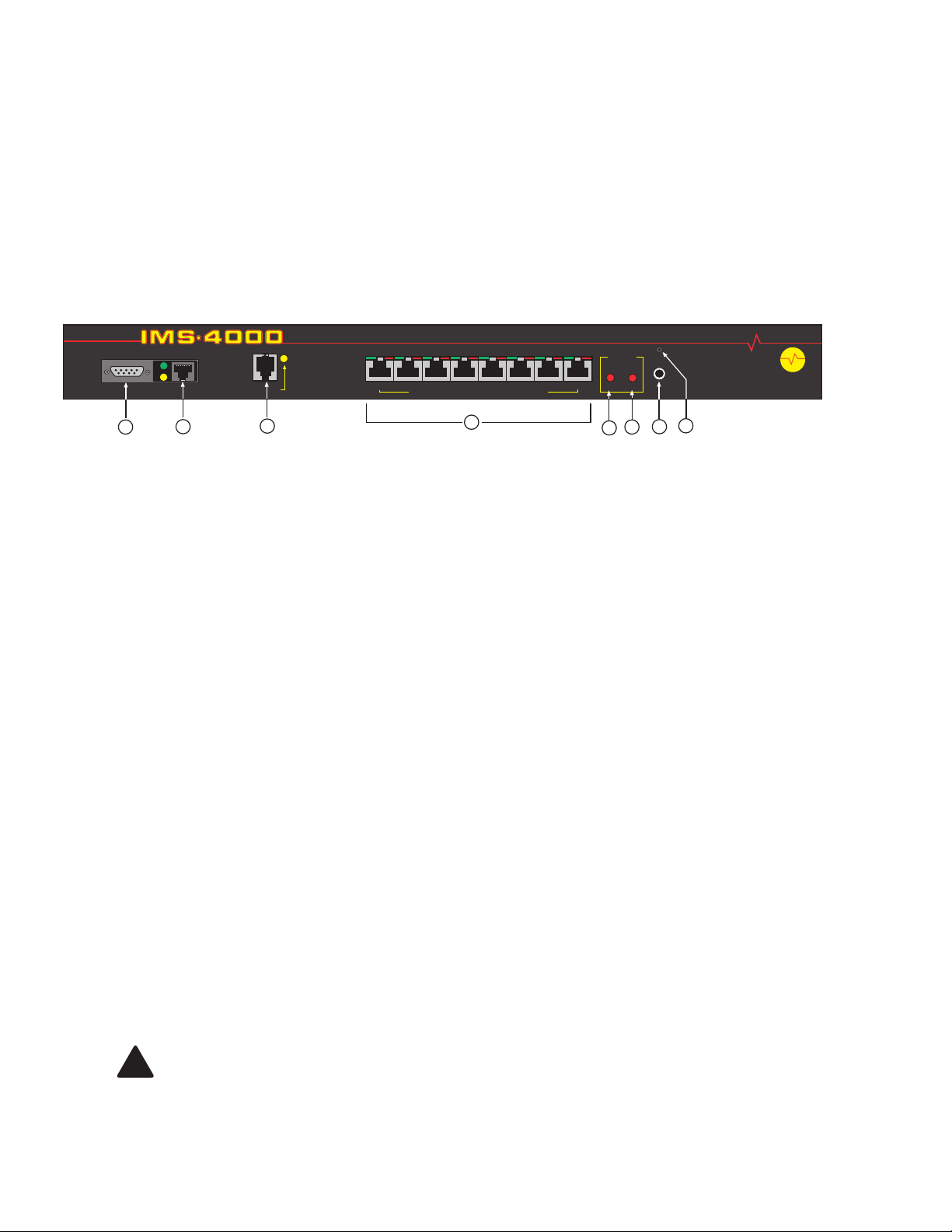
The front panel contains connections for eight sensor inputs, microphone input, Ethernet port, serial
port, and status LEDs. See figure below:
Figure 1: Front Panel Layout of the D-100 Host
1 Serial Port
2 Ethernet port (10Base-T)
3 Phone line
4 Sensor Inputs (8)
5 Battery Power Alarm LED
6 AC Power Alarm LED
7 External Microphone Input
8 Internal Microphone
Serial Port
The RS-232 serial port is used to conf igure network settings. The port operates at 9600 baud, no
parity, and 1 stop bit.
RJ-45 10BASE-T Ethernet Port
This jack is for connecting to your network so that the D-100 Host can communicate with the
D-100 Nodes and ping selected network servers and/or services. Two LEDs indicate received
data (green) and transmitted data (yellow).
Phone Jack
Connect the D-100's Phone jack to a standard 2-wire analog phone line. The unit dials using
touch-tones, with loop start only. The D-100 will recognize ringer frequencies from 16 to 60 Hz
and will operate with all standard analog telephone systems that accept tone dialing.
Certain private telephone systems and public switching equipment may not accept the unit’s dialing
or may generate an unacceptable ring signal. In those cases, a dedicated line may be required for
the unit. Consult the supplier of your telephone system if you encounter problems.
CAUTION: Never install telephone wiring during a lightning storm. Never install
telephone jacks in wet locations unless the jack is specifically designed for wet
locations. Never touch uninsulated telephone wires or terminals unless the telephone
line has been disconnected at the network interface. Use caution when installing or
modifying telephone lines.
12
SERIAL
1
ETHERNET
Infrastructure Monitoring System
1 2 3 4 5 6 7 8
PHONE
3
1 2 3 4 5 6 7 8
Environmental Sensor Inputs
4
POWER
ALARM
BAT
5
AC
MIC
8
72
6
Host
M
I
S
O
L
U
S
O
I
T
N
!

Physical Description
13
Sensor Inputs
The sensor inputs are designed to interface with D-100 series sensors (See Appendix C). The
use of RJ-45 jacks for sensor inputs allows the use of existing structured cabling to connect remote
sensors.
Since the sensor produces an analog signal, it must connect directly to the Host or Node. The path
from the sensor to the D-100 unit CANNOT pass through a network Hub or Switch.
Sensor
Input LEDs
Each sensor input has two LEDs (red and green) to indicate the present status of the input. The
key below describes the multiple modes of operation.
Mode 0: No sensor at input
Green: OFF
Red: OFF
Mode 1: Sensor present—No alarms
Green: ON
Red: OFF
Mode 2: Alarm detected but has not exceeded recognition time
Green: FAST BLINK
Red: FAST BLINK
Mode 3: New alarm exists and not yet acknowledged
Green: SLOW BLINK
Red: SLOW BLINK
Mode 4: Input is in normal range, but alarm is still unacknowledged
Green: ON
Red: SLOW BLINK
Mode 5: Alarm has been acknowledged, but input is still out of range
Green: SLOW BLINK
Red: ON
Mode 6: Sensor in trouble
Green: QUICK FLASH
Red: QUICK FLASH
AC Power and Battery
LEDs
The AC Power and Battery alarm status is indicated by two red LEDs. Their modes of operation
are described below.
Mode 1: No Alarm
LED: OFF
Mode 2: Alarm detected but has not exceeded recognition time
LED: FAST BLINK
Mode 3: New Alarm exists and not yet acknowledged
LED: SLOW BLINK
Mode 4: Alarm has been acknowledged but input is still out of range
LED: ON
 Loading...