

DataSouth Documax A6300 Series User Manual

Documax
A6300 Series
User’s Manual
Part No. 107052
Rev. B

Datasouth Computer Corporation
Sales: 1-800-476-2120
Fax: 1-704-525-6104
Service/Parts: 1-800-476-2450
This binder contains the User’s Manual. If you would like to order related
publications, fill in the appropriate information below and fax or call the
Service/Parts number listed above:
[ ]Programmer’s Manual (Part No. 104629).........................................$45.00
[ ]Maintenance Manual (Part No. 104560)...........................................$58.00
Please fill in the blanks below so that we may provide you with the correct
information:
Name ______________________________________________________
Company Name ______________________________________________
Business Address _____________________________________________
City ________________________State ____________Zip_____________
Business Phone ______________________Fax No. __________________
*Important Information
*Printer Serial No. __________________Date of Purchase ___________
*Firmware Option (Run a “Print Profile”) ________________________
Title Page
Table Of Contents

Chapter 1 Installation And Start Up
1.1 Introduction......................................................................... 1-1
1.2 Quick Start Up Procedure................................................... 1-2
1.3 Unpack The Printer.............................................................. 1-4
1.4 Choosing A Place For The Printer....................................... 1-5
1.5 Printer Parts......................................................................... 1-6
1.6 Install The Power Cord........................................................ 1-9
1.7 Install The Ribbon Cartridge................................................ 1-11
1.8 Printer Self Test................................................................... 1-18
1.9 Interfacing............................................................................ 1-20
1.10 RS-232 And RS-422 Serial Interface Configuration............ 1-23
Chapter 2 Keypad Operation
2.1 Keypad Configuration.......................................................... 2-1
2.2 Ready LED.......................................................................... 2-2
2.3 On/Off Line Key Functions.................................................. 2-3
2.4 LCD Display........................................................................ 2-4
Chapter 3 Forms Handling
3.1 Recommended Types And Sizes.......................................... 3-1
Continuous Forms (Main Paper Path)................................. 3-1
Continuous Forms (Alternate Paper Path)........................... 3-1
Cut Sheet Forms (Cut Sheet Path)....................................... 3-1
3.2 Paper Paths.......................................................................... 3-2
3.3 Load Forms.......................................................................... 3-3
3.4 Format Page......................................................................... 3-10
3.5 Top of Form Adjustment
(Adjusting First Printline Location).................................................
3-12
3.6 Tear Off Adjustment.............................................................
3-14
3.7 Form Thickness Adjustment..................................................
3-16
3.8 Heavy Forms Adjustment......................................................
3-19
3.9 Changing From Main Paper Path To Alternate Path.............
3-20
3.10 Changing From Alternate Paper Path
To Main Paper Path..............................................................
3-22
3.11 Paper Out Condition.............................................................
3-23

3.12 Automatically Changing Paper Paths On Paper Out.............
3-24
3.13 Selecting Paper Paths Using The Profile Key.......................
3-25
3.14 Selecting Paper Paths From The Host
Computer Using DPCL Command.......................................
3-27
Chapter 4 Features And Profiles
i
4.1 Features.................................................................................
4-1
4.2 Profiles..................................................................................
4-2
Profile Name/Feature Value..................................................
4-2
4.3 Setup Mode Key Functions...................................................
4-3
4.4 LCD Display In Setup Mode................................................
4-5
4.5 Profile Feature Listing...........................................................
4-6
4.6 Changing Features In A Profile.............................................
4-7
4.7 User Programmable Features................................................
4-10
Menu 1 Page Format.............................................................
4-10
Menu 2 Forms Control..........................................................
4-11
Menu 3 Personality..............................................................
4-14
Menu 4 Printer Control........................................................
4-16
Menu 5 Serial Control..........................................................
4-28
Menu 6 Parallel Control.......................................................
4-29
Menu 7 Profile Control........................................................
4-20
Menu 8 Form Thickness Control.........................................
4-21
Menu 9 Diagnostics.............................................................
4-22
Chapter 5 Troubleshooting And Maintenance

5.1 Scheduled Maintenance.........................................................
5-1
5.2 Error Messages.....................................................................
5-3
Paper Out Condition (Main Tractors)...................................
5-3
Paper Out Condition (Alternate Tractors)............................
5-4
Paper Jam..............................................................................
5-5
Carriage Jam.........................................................................
5-6
Keypad Lockout....................................................................
5-7
5.3 Printer Diagnostics................................................................
5-8
Print Profile...........................................................................
5-9
P/N: 104217 - xx (Firmware Part Number)..........................
5-10
Test Printhead.......................................................................
5-11
Run Mode Test.....................................................................
5-12
Run Self Test.........................................................................
5-13
Display Mode........................................................................
5-13
5.4 Troubleshooting....................................................................
5-14
5.5 Troubleshooting Table..........................................................
5-15
ii

Appendices
Title Page
Appendix A: Printer Specifications
A.1 Printer Characteristics.......................................................... A-1
Printhead:............................................................................. A-1
Maximum Line Length:........................................................ A-1
Vertical Pitch:...................................................................... A-1
A.2 Emulation............................................................................. A-1
A.3 Font Specifications............................................................... A-1
Available Fonts/Typefaces:.................................................. A-1
Graphic Densities:................................................................ A-2
International Character Sets:................................................ A-2
A.4 Paper Feed Specifications.................................................... A-2
Paper Types:........................................................................ A-2
Access:................................................................................. A-2
Feed Direction:.................................................................... A-3
Forms Tear Off:................................................................... A-3
Paper Slew (Paper Advance):.............................................. A-3
A.5 Forms Mode Change............................................................ A-3
Parking Forms:..................................................................... A-3
Tear Off:.............................................................................. A-3
A.6 Communications Interface................................................... A-3
Communications Buffer Size:.............................................. A-3
RS-232/RS-422 Serial Interface Characteristics:................. A-3
Centronics-Compatible Parallel Interface3
Characteristics:.................................................................. A-3
A.7 Operator Panel Functional Description................................ A-4
Display Description:............................................................. A-4
Key Switch Layout:............................................................. A-4
A.8 Ribbon Cartridge/Drive........................................................ A-4
A.9 Physical................................................................................ A-4
A.10Electrical.............................................................................. A-4
Power Requirements:........................................................... A-4
A.11Shock And Vibration........................................................... A-4
A.12Environmental...................................................................... A-5
Temperature:........................................................................ A-5
Humidity:............................................................................. A-5
Noise Level:......................................................................... A-5
Electrostatic Discharge:....................................................... A-5
A.13Compliance.......................................................................... A-5
Safety:.................................................................................. A-5
EMC:................................................................................... A-5

Title Page
iii
Appendix B: Interface Specifications
B.1 Parallel Interface.................................................................. B-1
Data Transmission:.............................................................. B-1
Synchronization:.................................................................. B-1
Handshaking:....................................................................... B-1
Logic Level:......................................................................... B-1
B.2 Parallel Interface Enable/Disable.......................................... B-5
B.3 RS-232 Serial Interface........................................................ B-6
Data Transfer Rates (Baud Rate):........................................ B-6
Synchronization:.................................................................. B-6
Data Format:........................................................................ B-6
Handshaking Protocols........................................................ : B-6
B.4 Serial Interface Selection..................................................... B-9
RS-232 Serial Interface Connector Pin Assignment............ B-10
RS-422 Serial Interface Connector Pin Assignment............ B-11
Appendix C: Default Tables
C.1 Menu 1: Page Format........................................................ C-1
C.2 Menu 2: Forms Control..................................................... C-1
C.3 Menu 3: Personality........................................................... C-2
C.4 Menu 4: Printer Control..................................................... C-2
C.5 Menu 5: Serial Interface.................................................... C-2
C.6 Menu 6: Parallel Interface.................................................. C-3
C.7 Menu 7: Profile Control..................................................... C-3
C.8 Menu 8: Form Thickness Control...................................... C-3
C.9 Menu 9: Diagnostics.......................................................... C-3
C.10 Menu 10: System Control.................................................... C-4
Appendix D: System Administration Features
D.1 Features Available In System Control Menu....................... D-1
Menu 10 System Control.................................................... D-2
D.2 Key Functions That Can Be Locked.................................... D-4
Appendix E: Ribbon Life Monitor................................... E1
E.1 Ribbon Monitor Operation................................................... E-2
E-2 Resetting the Ribbon Life Monitor Feature......................... E-3
Title Page
iv

Appendix F: ASCII Conversion Chart............................ F-1
Appendix G: ASCII Character Sets
G.1 ASCII Character Sets.......................................................... G-1
G.2 7 Bit ASCII Character Set................................................... G-2
G.3 IBM Code Page 437 Symbol Set......................................... G-4
G.4 IBM Code Page 850 Symbol Set......................................... G-6
G.5 Epson Italic Symbol Set....................................................... G-8
G.6 Epson Graphics Symbol Set................................................. G-10
G.7 Epson Italic Graphics Symbol Set........................................ G-12
G.8 DEC Supplemental Symbol Set........................................... G-14
G.9 Nationality Overlay Character Set....................................... G-16
Appendix H: Escape Sequence Quick Reference
H.1 Epson FX............................................................................. H-1
H.2 IBM Proprinter.................................................................... H-4
H.3 DEC LA-120........................................................................ H-7
H.4 TI-885 (Optional)................................................................ H-10
H.5 DS-180................................................................................. H-12
H.6 DPCL Command Sequence Summary................................. H-15
v

THIS PAGE INTENTIONALLY LEFT BLANK
vi

List of Figures
Title Page
Figure 1-1 External Printer Parts (Standard Model) (Sheet 1 of 2) ..... 1-6
Figure 1-1 External Printer Parts (Dual Path) (Sheet 2 of 2)............... 1-7
Figure 1-2 Internal Printer Parts (Standard Model) (Sheet 1 of 2)....... 1-7
Figure 1-2 Internal Printer Parts (Dual Path) (Sheet 1 of 2)................ 1-8
Figure 1-3 Back Printer Parts (All Options)......................................... 1-8
Figure 1-4 Install Power Cord.............................................................. 1-10
Figure 1-5 Open Access Cover (Both Options).................................... 1-12
Figure 1-6 Form Thickness Adjustment Knob...................................... 1-13
Figure 1-7 Remove Ribbon Guide........................................................ 1-14
Figure 1-8 Position Ribbon Cartridge In Printer.................................. 1-15
Figure 1-9 Install Ribbon Cartridge..................................................... 1-26
Figure 1-10 Install Ribbon Guide.......................................................... 1-27
Figure 1-11 Self Test Sample................................................................ 1-29
Figure 1-12 Interface Connectors.......................................................... 1-20
Figure 2-1 Keypad Configuration......................................................... 2-1
Figure 2-2 Ready LED......................................................................... 2-2
Figure 2-3 Primary Keys...................................................................... 2-3
Figure 3-1 Paper Feed Paths................................................................. 3-2
Figure 3-2 Load Paper In Tractors (Main Path Shown)....................... 3-4
Figure 3-3 Forms Loading.................................................................... 3-6/3-7
Figure 3-4 Placement of Continuous Forms......................................... 3-7
Figure 3-5 Turn On Power................................................................... 3-7
Figure 3-6 Press Load Key................................................................... 3-8
Figure 3-7 Loading Cut Sheet Form..................................................... 3-9
Figure 3-8 Tear Bar Scale.................................................................... 3-10
Figure 3-9 Set First Print Line.............................................................. 3-13
Figure 3-10 Printer Located Under Countertop.................................... 3-15
Figure 3-11 Manually Move Form Thickness Adj. Knob..................... 3-18
Figure 3-12 Main & Alternate Paper Paths (Cut Sheet Not Shown).... 3-21
Figure 4-1 Setup Mode Keys................................................................ 4-3
Figure 4-2 Changing Features In A Profile.......................................... 4-7
Figure 5-1 Cleaning the Printer............................................................ 5-2
Figure 5-2 Main Tractor Path.............................................................. 5-3
Figure 5-3 Alternate Tractor Path........................................................ 5-4
Figure 5-4 Print Profile......................................................................... 5-9
Figure 5-5 Printhead Test..................................................................... 5-11
Figure 5-6 Run Mode Test................................................................... 5-12
Figure 5-7 Run Self Test...................................................................... 5-13
Figure 5-8 Display Mode Test.............................................................. 5-14
vii

Title Page
Figure B-1 36 Pin Parallel Interface Connector.......................... B-2
Figure B-2 Signal Timing Pattern (Sheet 1 of 2)........................ B-3
Figure B-2 Signal Timing Pattern (Sheet 2 of 2)........................ B-4
viii

Chapter 1:..............................Installation and Start Up
1.1 Introduction
This dot matrix impact printer provides high-speed performance, plus a rugged, roundthe-clock duty cycle, and flexibility to handle a number of printing applications.
Feature Highlights:
Straight through paper path for optimum forms handling.
Eighteen wire ballistic printhead and flat metal print platen to assure legibility on every
copy.
Demand document printing.
Automatic Form Thickness adjustment.
Forms parking and reloading at the touch of a key.
Ten user-defined profiles for quick forms set up.
Paper path selection by profile selection, downline command or active interface.
Emulations: Epson FX, DEC LA 120, IBM Graphics, IBM Proprinter XL, DS-180.
Automatic voltage select power supply.
Ribbon Life Monitor feature that tracks ribbon usage.
Options:
a. Second pin feed paper path
b. Cut sheet paper path
c. IBM Coax, IBM Twinax interfaces, Ethernet, Token Ring
d. Quiet cover set
e. Barcodes
1-1

1.2 Quick Start Up Procedure
The following is an abbreviated installation and start up procedure provided for users who
are already familiar with printer products. If you are not experienced with printers, follow
all of the instructions in Chapter 1 for setting up printer.
1. Place the printer on a suitable stand or countertop.
CAUTION
ENSURE THAT FRONT RUBBER
FEET ARE AT LEAST ONE INCH
FROM THE EDGE OF THE
TABLE.
2. Install ribbon cartridge following the instructions on the box.
3. Attach the power cord.
4. Turn printer on.
5. Position left tractor with Alignment mark on printer. Position front paper guides
and rear paper supports equally across the width of the form. Load 8.5" paper in
tractors.
6. Press the Load key (or insert a cut sheet).
7. Open the Keypad Door to enter Setup Mode.
8. Use the Quick Access key, the Value keys, and the Enter key to set margins.
9. Close the Keypad Door.
10. Press the Profile key to save settings.
CAUTION
IMPROPER MARGIN SETTINGS
CAN LEAD TO PRINTHEAD
DAMAGE! DO NOT PRINT OFF
THE EDGE OF THE FORM.
1-2
11. Press the Feature key to display "Self Test".
12. Press the Enter key.

Press the Enter key to start the self-test. Press the Enter key or close the Setup Door to
stop the self-test.
1.3 Unpack The Printer
Remove the following from the shipping carton:
Dot Matrix Printer
1-3

Ribbon Cartridge
Power Cord
Accessory Kit
User's Manual
Three-Ring Binder
Warranty card
If any items are missing, please contact your distributor. Save the shipping carton and all
packing materials. These items will be needed in the event the printer must be shipped.
CAUTION
SHIPPING THE PRINTER IN
ANY CONTAINER OTHER
THAN ITS ORIGINAL
PACKAGING MAY RESULT IN
SHIPPING DAMAGE AND MAY
VOID THE PRINTER
WARRANTY.
1-4
1.4 Choosing A Place For The Printer
The printer weighs approximately 45 pounds. Its dimensions are:
17.0 inches (431 mm) wide x 15.7 inches (398 mm) deep x 12.3 (312 mm) inches
high (Dual tractor, top roller versions).

17.0 inches (431 mm)wide x 15.7 inches (398 mm) deep x 11.3 inches (287 mm)
high (Standard model).
17.0 inches (431 mm) wide x 16.7 inches (424 mm) deep x 12.3 inches (312 mm)
high (Cut Sheet model).
Location
1. To permit air flow and proper cooling, do not place anything closer than 2 inches
(50mm) to the printer.
2. Allow 6 inches to the right of the printer for access to the Form Thickness
Adjustment knob.
3. For continuous printing and accumulation of forms, allow sufficient room behind
the printer for cables and stacking forms.
4. Place the printer on a sturdy level surface and align lower front edge of printer
with table edge. The feet should be at least one inch from the edge of the table.
5. Locate the printer near a grounded power receptacle and use the power cord
provided. Do not use an extension cord to connect the printer.
6. Avoid the following:
Direct sunlight or excessively illuminated areas
Direct placement in front of air conditioning or heating vents
Extreme high or low temperatures
Exposure to excessive dirt or dust
Exposure to vibration or mechanical shock
Excessive humidity or condensation
1.5 Printer Parts
Four basic models of the printer are available.
1-5
Standard straight tractor paper path with standard access cover.
Straight tractor paper path with top roller set and sound reduction access cover.
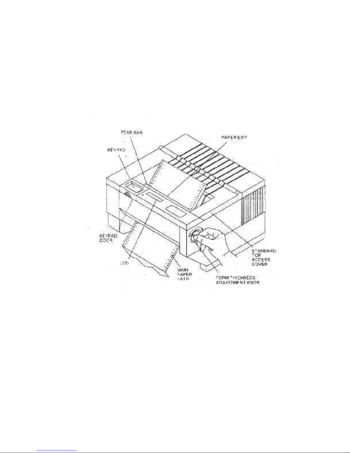
Dual tractor path (straight and 45º alternate path) with top roller set and sound
reduction access cover.
Straight tractor path and cut sheet (Friction Feed) path with top roller set and
sound reduction access cover.
Use the following illustrations to locate the major printer parts for each model. The
standard model is used to illustrate most of the procedures in this manual.
Figure 1-1. External Printer Parts (Standard Model)
1-6
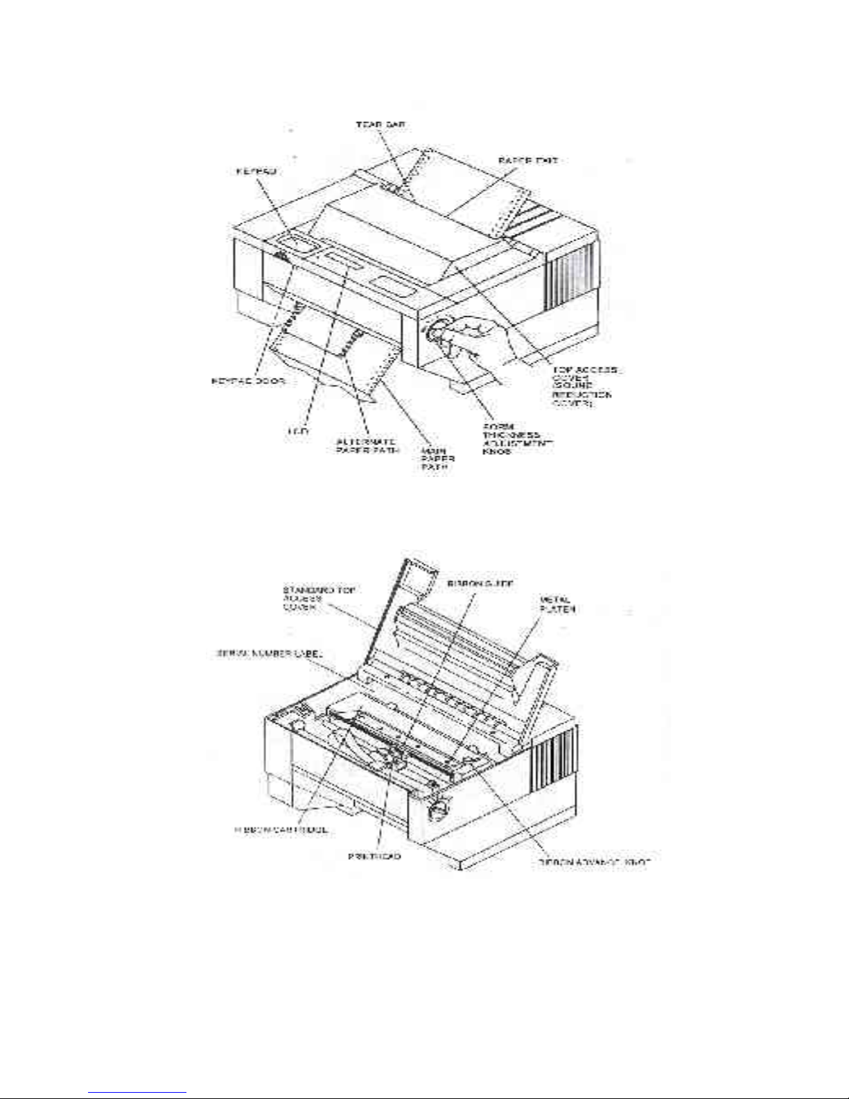
Figure 1-1. External Printer Parts (Dual Path And Sound
Reduction Access Cover)
Figure 1-2. Internal Printer Parts (Standard Model)
1-7
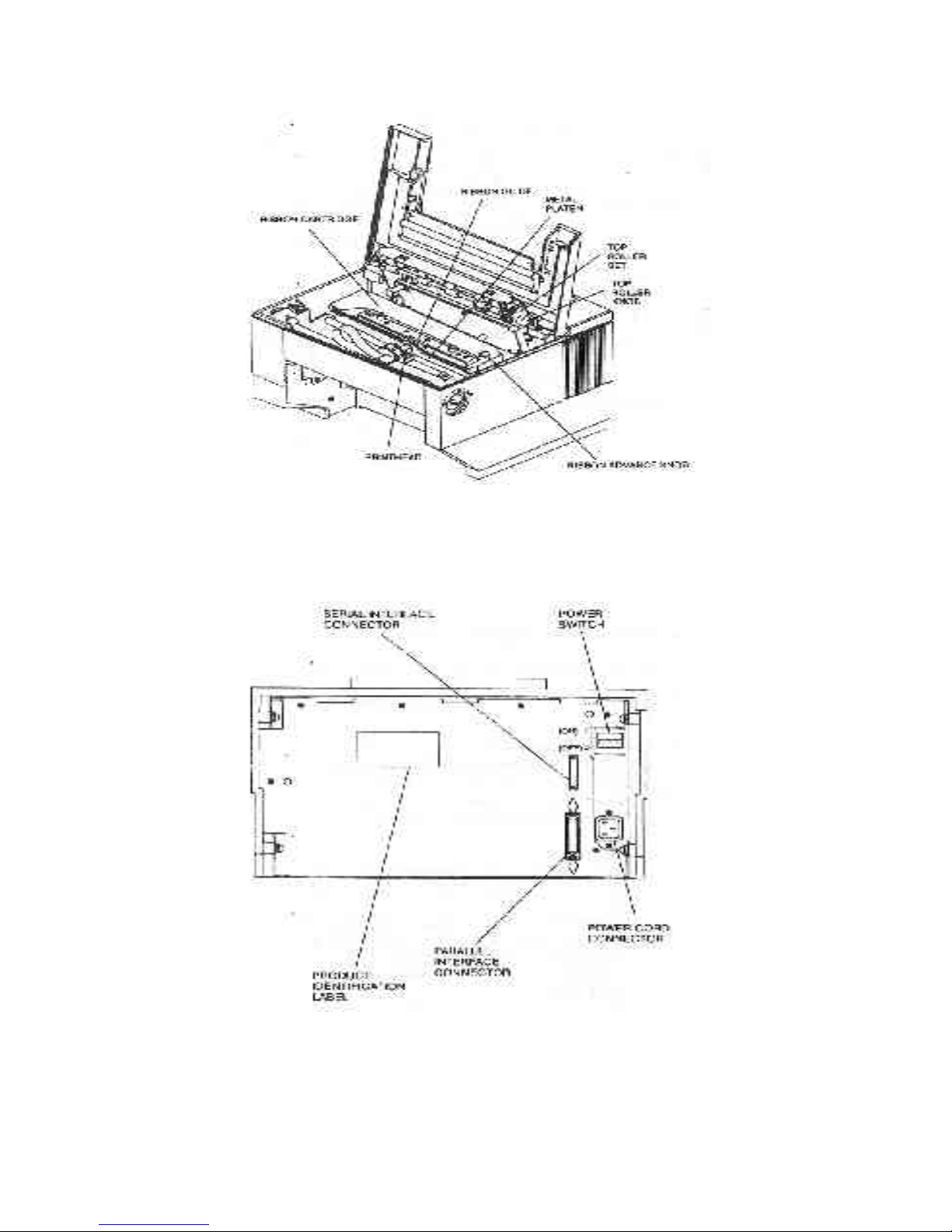
Note: Keypad assembly is not shown in order to identify printhead.
Figure 1-2. Internal Printer Parts (w/ Top Roller Option)
1-8
Figure 1-3. Back Printer Parts (All Options)

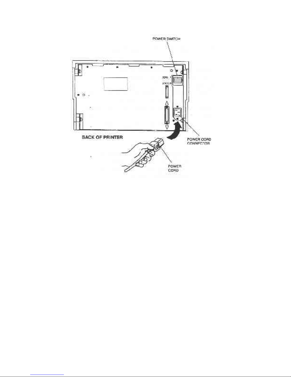
1.6 Install The Power Cord
1. Set the power switch to Off. (See Figure 1-4).
2. Install the power cord into the printer as shown in Figure 1-4.
3. Install the plug end of the power cord into a grounded AC outlet. A grounded
outlet must be used. Plugging the printer into an ungrounded outlet may result in
increased radio frequency noise generation, erratic printer operation, or electrical
shock.
CAUTION
CONNECTING THIS EQUIPMENT TO AN UNGROUNDED
POWER RECEPTACLE CAN
RESULT IN ELECTRICAL
SHOCK.
4. Set the power switch to ON. The alarm will sound 3 short tones and the printer
will display:
Paper Out: Main
1-9
1-10
Figure 1-4. Install Power Cord

1.7 Install The Ribbon Cartridge
To prolong ribbon life, the printer is shipped without the cartridge installed. The
following procedure is written for both initial installation and ribbon replacement.
This printer is equipped with a Ribbon Life Monitor Feature that tracks ribbon usage.
When the ribbon life reaches its set limit, the LCD will indicate a “Check Ribbon” or
“Replace Ribbon” status. For detailed information on this feature refer to Appendix E.
1. Press the On/Off Line key to display "off line" status.
Note
If paper is loaded, press PARK key
to park the form in the tractors.
The ribbon cartridge cannot be
installed if paper is loaded.
2. Open top access cover and lift roller assembly on models so equipped as shown in
Figure 1-5.
The display will indicate:
< Cover Open >
1-11
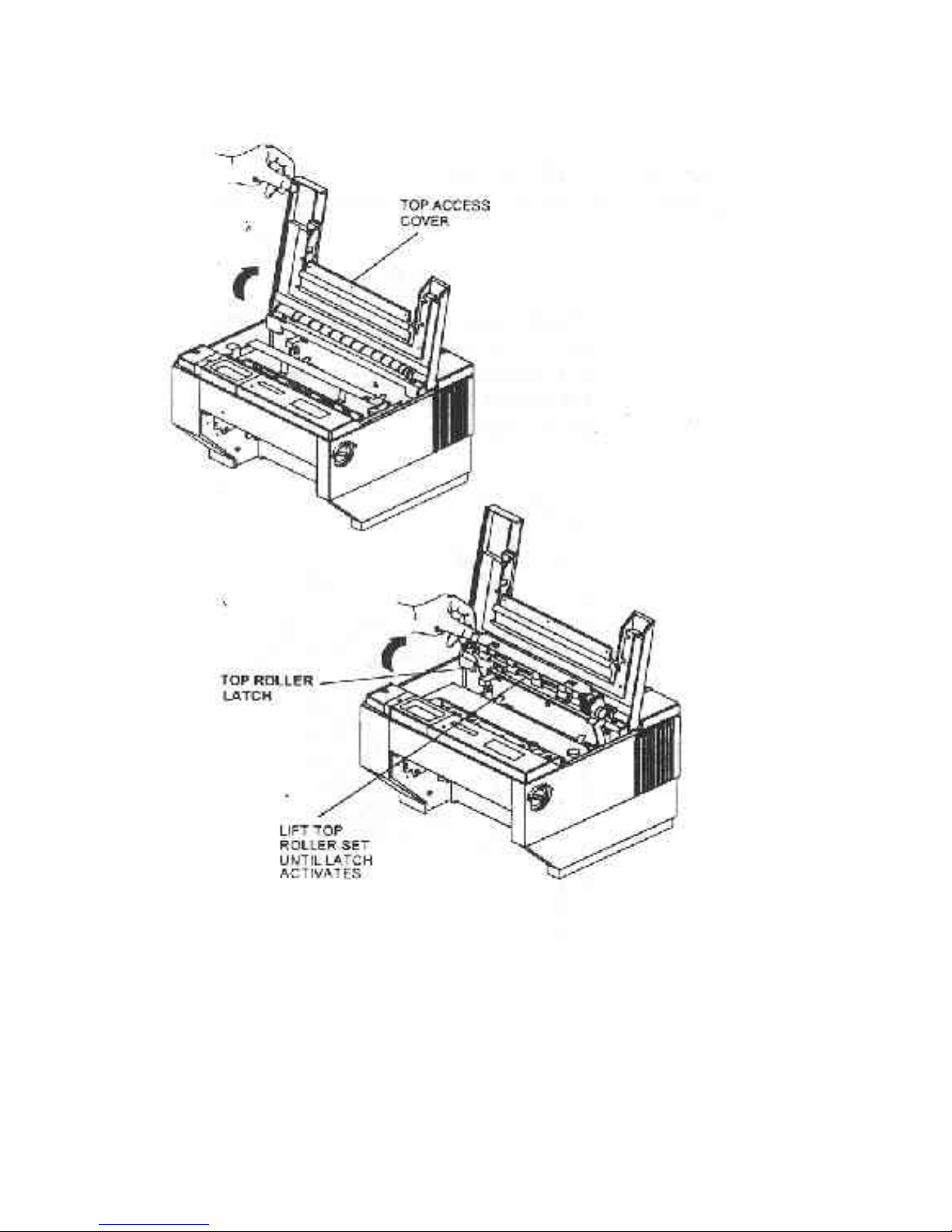
Figure 1-5. Open Access Cover (Both Options)
1-12
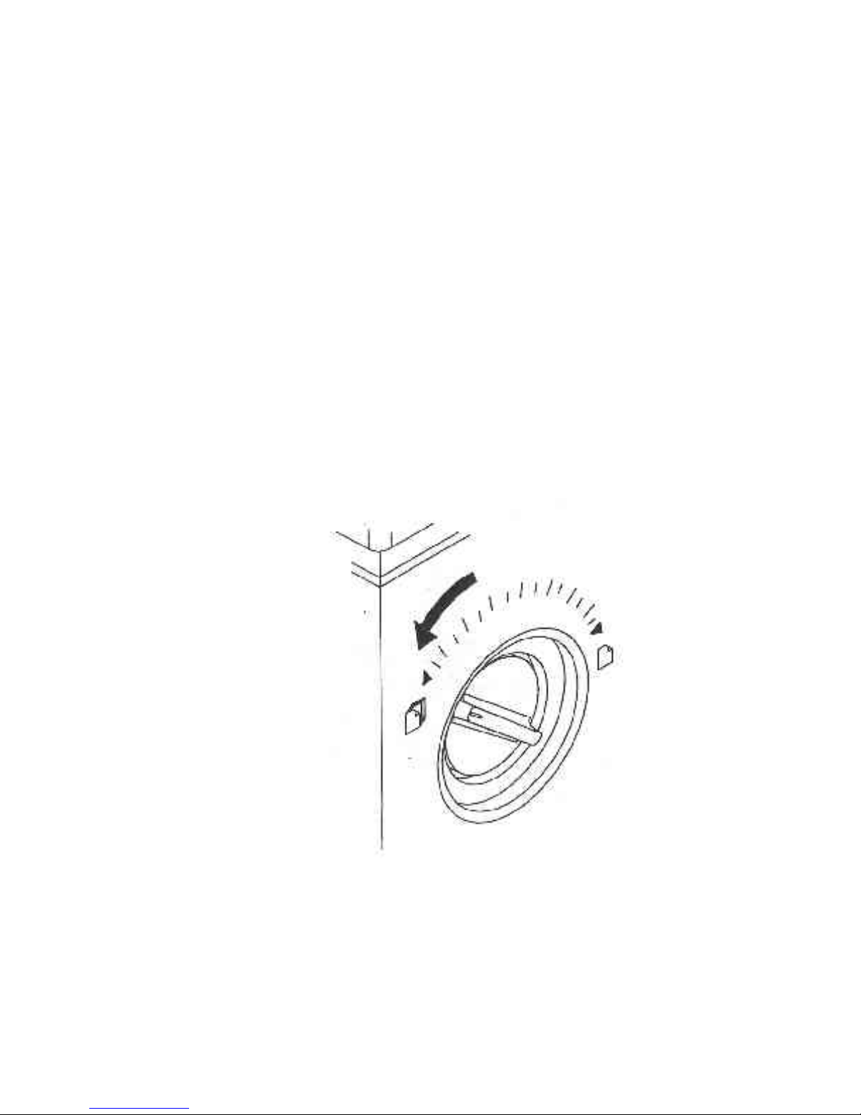
3. Check the Form Thickness Adjustment Knob to be sure that it is in the first
NOTE
When replacing the ribbon, the
Form Thickness Adjustment Knob
will automatically move away from
the form when the paper is parked
in the tractors.
position as shown in Figure 1-6.
Figure 1-6. Form Thickness Adjustment Knob
1-13
Note
Steps 4 and 5 are not required for
initial ribbon installation.
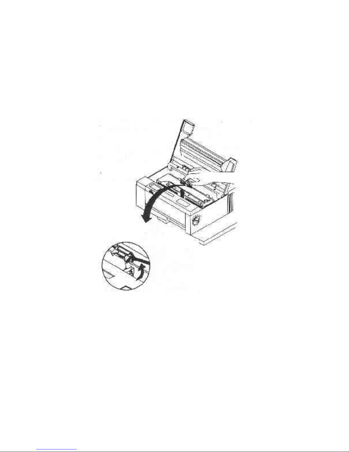
4. Remove the ribbon guide from printhead (lift up and rotate towards front).
5. Remove ribbon cartridge from printer.
1-14
Figure 1-7. Remove Ribbon Guide
WARNING
PRINTHEAD GETS HOT
DURING OPERATION. USE
CARE WHEN HANDLING THE
PRINTHEAD.
6. Move the printhead to the center of the printer.
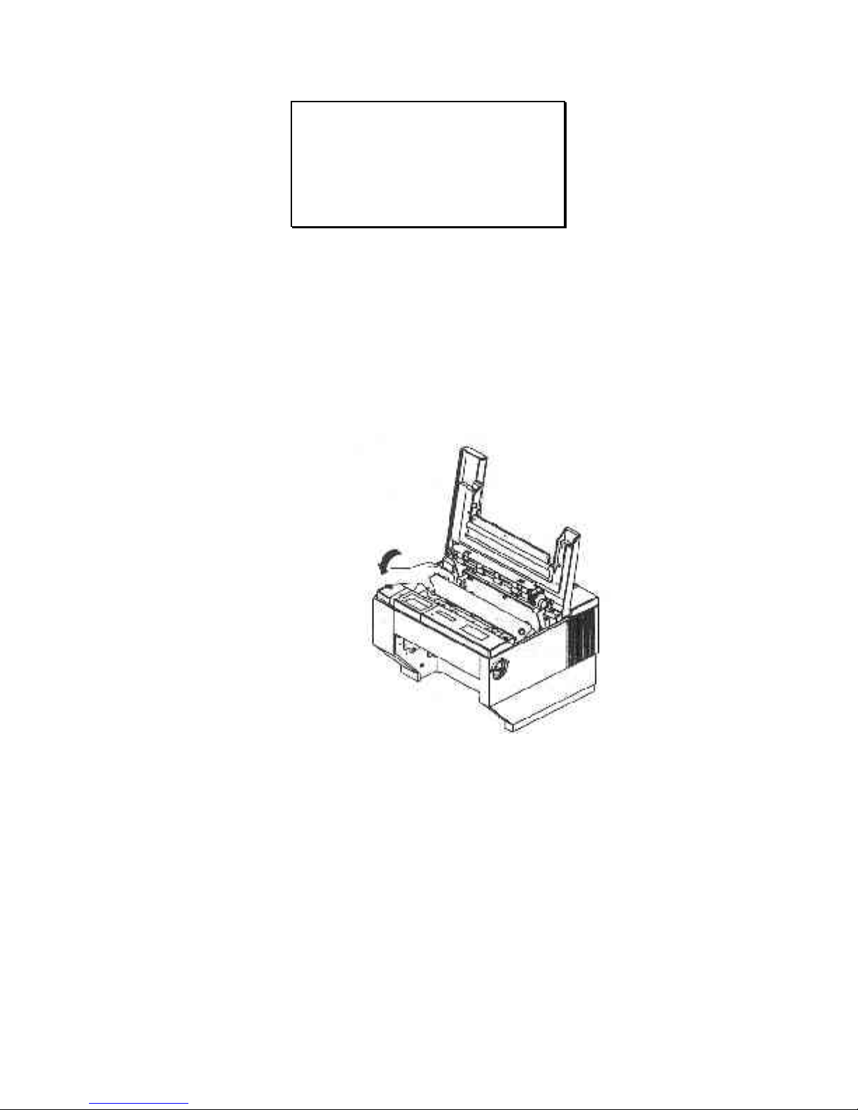
7. Remove slack from the ribbon by turning the blue knob on the cartridge in the
direction shown by the arrow on the knob.
8. Lower ribbon cartridge towards slots in printer. Ensure that ribbon loop is in
front of platen and that ribbon is not twisted.
9. Drop the ribbon cartridge into the ribbon alignment slots.
Figure 1-8. Position Ribbon Cartridge In Printer
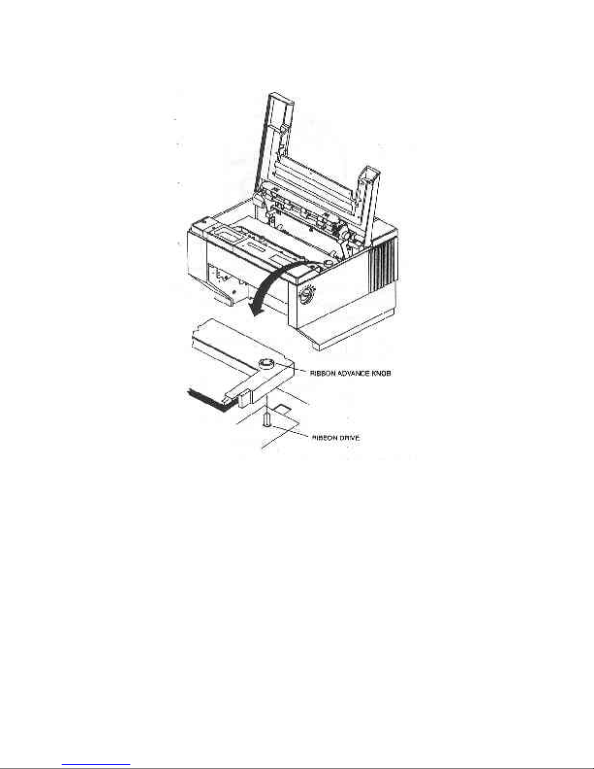
10. If the ribbon cartridge does not seat squarely on the ribbon drive, rotate the
Ribbon Advance Knob in the direction indicated by the arrow on the knob until the
cartridge drops into place on the ribbon drive.
1-15
11. With ribbon guide tilted to front of printer, place the guide on printhead nose.
Push down on ribbon guide until it snaps into place.
1-16
Figure 1-9. Install Ribbon Cartridge
Figure 1-10. Install Ribbon Guide

12. Remove any slack from the ribbon by turning the Ribbon Advance Knob in the
direction of the arrow marked on the knob.
13.Close the top access cover. The display alternates the following message:
Ribbon Replaced?
Y=Profile N=Onln
14 Press the Profile key to indicate a new ribbon was installed.
1-
17

1.8 Printer Self Test
This test is used to verify printer operation. Before performing the printer self-test, refer
to Section 3.3 Load Forms page 3-3 for instructions on loading paper in the printer.
To start the test:
CAUTION
MARGINS ARE SET FOR 8.5"
(OR 80 COLUMN) PAPER.
PRINTING OFF OF FORM WILL
LEAD TO PRINTER DAMAGE.
1. Load 8.5" forms.
2. Open the Keypad Door.
3. Press the Feature key once. The LCD will Show "Run Self Test".
4. Press the Enter key. The Printer self test will start (Figure 1-12). The display will
alternate between the following:
< Diagnostics >
`Enter' To Stop
5. The self test may be stopped by pressing the Enter key or by closing the Keypad
Door.
1-18

Figure 1-11. Self Test Sample
1-19
 Loading...