

Page 1

DATASONICS
SIS-1500
Seafloor Imaging System
System Manual
June 1998
Datasonics, Inc.
1400 Route 28A
Cataumet, MA 02534
U.S.A.
Tel: (01) 508-563-5511
Fax: (01) 508-563-9312
Page 2

ii DATASONICS
Volume ISystem Manual June 1998
Page 3

SIS-1500 Seafloor Imaging System iii
Notices
Proprietary Information
The information, descriptions, photos and illustrations in this manual are the
property of Datasonics, Inc. Materials may not be reproduced or
disseminated without the prior written consent of Datasonics.
Warranty
On standard catalog products, Seller warrants the products delivered under
this contract to be free from defects in material and workmanship at the time
of delivery to the F.O.B. point specified in the order, its liability under this
warranty being limited to repairing or replacing, at Seller’s option, items which
are returned to it FREIGHT PREPAID within one (1) year from delivery to the
Buyer and found to Seller’s satisfaction, to have been so defective. Items
shall be returned to the Buyer FREIGHT PREPAID.
On services, Seller warrants that all work performed by the employees will be
done in a workmanlike manner. Seller’s liability under this warranty is limited
to remedying at its expense any work found to Seller’s satisfaction not so
performed, provided however, Seller is notified of any claims within three (3)
months from the date the work is performed.
In no event shall Seller be liable for consequential damages. NO PRODUCT
IS WARRANTED AS BEING FIT FOR A PARTICULAR PURPOSE AND
THERE IS NO WARRANTY OF MERCHANTABILITY. This warranty applies
only if: (i) the items are used solely under the operating conditions and in the
manner recommended in Seller’s instruction manual, specifications, or other
literature; (ii) the items have not been missed or abused in any manner or
repairs attempted thereon; (iii) written notice of the failure within the warranty
period is forwarded to Seller and the directions for properly identifying items
returned under warranty are followed; and (iv) with return notice authorizing
Seller to examine and disassemble returned products to the extent Seller
deems necessary to ascertain the cause of failure. The warranties stated
herein are exclusive. THERE ARE NO OTHER WARRANTIES, EITHER
EXPRESSSED OR IMPLIED, BEYOND THOSE SET FORTH HEREIN, and
Seller does not assume any other obligation or liability in connection with the
sale or use of said products.
Any product or service repaired or replaced under this warranty shall be
warranted for the unexpired portion of the original warranty period only.
Notices
Page 4

iv DATASONICS
Liability
Datasonics assumes no liability for damages, losses or costs incurred
consequentially through operation or malfunction of Datasonics products.
Title
Title shall pass to the Buyer on delivery to the carrier at Cataumet,
Massachusetts, U.S.A. Risk of damage or loss following such delivery shall
be the Buyer's, and Datasonics shall in no way be responsible for safe arrival
of the shipment. Title shall so pass to the Buyer regardless of any provision
for payment of freight or insurance by Datasonics, and regardless of the form
of the shipping documents. If shipment is consigned to Datasonics, it shall be
for the purpose of securing the Buyer's obligations under contract.
Changes
Datasonics reserves the right to make changes in design or specifications at
any time without incurring any obligation to modify previously installed units.
This manual is provided for informational and reference purpose only and is
subject to change without notice.
Volume ISystem Manual June 1998
Page 5

SIS-1500 Seafloor Imaging System v
Preface
Congratulations on your purchase of the SIS-1500 Seafloor Imaging System!
The SIS-1500 delivers high resolution sidescan imagery using advanced
Chirp technology.
This manual is divided into six sections:
Section 1 - Overview describes the major system components and
explains Chirp sonar technology.
Section 2 - Specifications lists the specifications for the shipboard and
subsea components of the system.
Section 3 - Setup and Deployment covers the unpacking and setup of
the hardware, configuration of system parameters, and a system startup
procedure that includes predeployment checks and tow vehicle
deployment.
Section 4 - Theory of Operation describes the circuit functions and
signal flows for both the shipboard and subsea components of the
system.
Section 5 - Maintenance covers routine maintenance and includes
troubleshooting guides, recommended test equipment, test and
calibration procedures, and tables of downlink commands and uplink
data.
Section 6 - Drawings includes the circuit board assembly drawings and
the wiring diagrams for the shipboard and subsea hardware components
of the system.
Notes and Warnings
Where applicable, special notes and warnings are presented as follows:
NOTE A referral to another part of this manual or to another reference; a
recommendation to check that certain criteria are met before proceeding
further in a step or sequence; or general information applicable to the setup
and operation of the SIS-1500 Seafloor Imaging System.
Preface
Page 6

vi DATASONICS
WARNING A reminder that dangerous or damaging consequences could
result if certain recommended procedures are not followed.
Comments
We welcome your comments and suggestions for improving our products and
documentation as well as developing better ways of serving you with acoustic
technology. Therefore, please contact Customer Service should you have
any comments or suggestions about this manual or the SIS-1500 Seafloor
Imaging System, or if you require service or support.
Please contact us at:
DATASONICS, INC.
Attention: Customer Service
1400 Route 28A
Cataumet, MA 02534
U.S.A.
Telephone: (01) 508-563-5511
FAX: (01) 508-563-9312
E-mail: [email protected]
http:\\www.datasonics.com
Volume ISystem Manual June 1998
Page 7

SIS-1500 Seafloor Imaging System vii
Contents
Notices . . . . . . . . . . . . . . . . . . . . . . . . . . . . . . . . . . . . . . . . . . . . . . . . . . .iii
Proprietary Information . . . . . . . . . . . . . . . . . . . . . . . . . . . . . . . . . . . . .iii
Warranty . . . . . . . . . . . . . . . . . . . . . . . . . . . . . . . . . . . . . . . . . . . . . . . . .iii
Liability . . . . . . . . . . . . . . . . . . . . . . . . . . . . . . . . . . . . . . . . . . . . . . . . . .iv
Title . . . . . . . . . . . . . . . . . . . . . . . . . . . . . . . . . . . . . . . . . . . . . . . . . . . . .iv
Changes . . . . . . . . . . . . . . . . . . . . . . . . . . . . . . . . . . . . . . . . . . . . . . . . .iv
Preface . . . . . . . . . . . . . . . . . . . . . . . . . . . . . . . . . . . . . . . . . . . . . . . . . . . v
Notes and Warnings . . . . . . . . . . . . . . . . . . . . . . . . . . . . . . . . . . . . . . . v
Comments . . . . . . . . . . . . . . . . . . . . . . . . . . . . . . . . . . . . . . . . . . . . . . .vi
Contents . . . . . . . . . . . . . . . . . . . . . . . . . . . . . . . . . . . . . . . . . . . . . . . . . vii
List of Figures . . . . . . . . . . . . . . . . . . . . . . . . . . . . . . . . . . . . . . . . . . . . .xi
List of Tables . . . . . . . . . . . . . . . . . . . . . . . . . . . . . . . . . . . . . . . . . . . .xiii
SECTION 1
SIS-1500 Overview . . . . . . . . . . . . . . . . . . . . . . . . . . . . 1-1
Main System Components . . . . . . . . . . . . . . . . . . . . . . . . . . . . . . . .1-3
Advantages of Chirp Sonar . . . . . . . . . . . . . . . . . . . . . . . . . . . . . . . .1-6
SIP-150 Sonar Image Processor . . . . . . . . . . . . . . . . . . . . . . . . . . .1-6
SIP-150 Sonar Image Processor Workstation . . . . . . . . . . . . . . . . . .1-7
Chirpscan3 Software . . . . . . . . . . . . . . . . . . . . . . . . . . . . . . . . . . . . . .1-8
Data Fusion and Storage . . . . . . . . . . . . . . . . . . . . . . . . . . . . . . . .1-8
Realtime Display and Image Processing . . . . . . . . . . . . . . . . . . . .1-8
Post-Processing of Data . . . . . . . . . . . . . . . . . . . . . . . . . . . . . . . . .1-9
Chirplink II Digital Multiplexer . . . . . . . . . . . . . . . . . . . . . . . . . . . . . .1-9
TTV-195 Tow Vehicle . . . . . . . . . . . . . . . . . . . . . . . . . . . . . . . . . . . . .1-9
Sidescan Sonar Transducer Arrays . . . . . . . . . . . . . . . . . . . . . . . . .1-10
Sonar Electronics . . . . . . . . . . . . . . . . . . . . . . . . . . . . . . . . . . . . . . .1-12
Optional Sensors . . . . . . . . . . . . . . . . . . . . . . . . . . . . . . . . . . . . . . . .1-12
Chirp Technology . . . . . . . . . . . . . . . . . . . . . . . . . . . . . . . . . . . . . . . .1-12
Across-Track Resolution . . . . . . . . . . . . . . . . . . . . . . . . . . . . . . . . .1-12
Along-Track Resolution . . . . . . . . . . . . . . . . . . . . . . . . . . . . . . . . . .1-13
Signal-to-Noise Ratio . . . . . . . . . . . . . . . . . . . . . . . . . . . . . . . . . . . . .1-13
Chirp Pulse Transmission and Reception . . . . . . . . . . . . . . . . . . . .1-14
Contents
Page 8

viii DATASONICS
SECTION 2
Specifications . . . . . . . . . . . . . . . . . . . . . . . . . . . . . . . 2-1
SIP-150 Sonar Image Processor . . . . . . . . . . . . . . . . . . . . . . . . . . 2-3
Physical Characteristics . . . . . . . . . . . . . . . . . . . . . . . . . . . . . . . . . . 2-3
Software . . . . . . . . . . . . . . . . . . . . . . . . . . . . . . . . . . . . . . . . . . . . . . . . 2-3
Computer . . . . . . . . . . . . . . . . . . . . . . . . . . . . . . . . . . . . . . . . . . . . . . . 2-3
Display . . . . . . . . . . . . . . . . . . . . . . . . . . . . . . . . . . . . . . . . . . . . . . . . . 2-4
Power Requirements . . . . . . . . . . . . . . . . . . . . . . . . . . . . . . . . . . . . . 2-4
Input/Output . . . . . . . . . . . . . . . . . . . . . . . . . . . . . . . . . . . . . . . . . . . . 2-4
Output Power . . . . . . . . . . . . . . . . . . . . . . . . . . . . . . . . . . . . . . . . . . . 2-5
Downlink Commands . . . . . . . . . . . . . . . . . . . . . . . . . . . . . . . . . . . . . 2-5
Downlink Responder Key . . . . . . . . . . . . . . . . . . . . . . . . . . . . . . . . . 2-5
Downlink Sonar Key . . . . . . . . . . . . . . . . . . . . . . . . . . . . . . . . . . . . . . 2-5
Uplink Vehicle Status and Sensor Data . . . . . . . . . . . . . . . . . . . . . . 2-6
Uplink Sonar Data . . . . . . . . . . . . . . . . . . . . . . . . . . . . . . . . . . . . . . . . 2-6
TTV-195 Tow Vehicle . . . . . . . . . . . . . . . . . . . . . . . . . . . . . . . . . . . . 2-6
Physical Characteristics . . . . . . . . . . . . . . . . . . . . . . . . . . . . . . . . . . 2-6
Sidescan Sonar . . . . . . . . . . . . . . . . . . . . . . . . . . . . . . . . . . . . . . . . . . 2-7
Sensors . . . . . . . . . . . . . . . . . . . . . . . . . . . . . . . . . . . . . . . . . . . . . . . . 2-7
SECTION 3
Setup and Deployment . . . . . . . . . . . . . . . . . . . . . . . . . 3-1
Unpacking . . . . . . . . . . . . . . . . . . . . . . . . . . . . . . . . . . . . . . . . . . . . . . . 3-3
Processor Setup . . . . . . . . . . . . . . . . . . . . . . . . . . . . . . . . . . . . . . . . . 3-5
Processor Hardware Connections . . . . . . . . . . . . . . . . . . . . . . . . 3-6
Workstation Connections . . . . . . . . . . . . . . . . . . . . . . . . . . . . . . . . . 3-6
Digital Multiplexer Connections . . . . . . . . . . . . . . . . . . . . . . . . . . . . 3-7
Connecting the Processor . . . . . . . . . . . . . . . . . . . . . . . . . . . . . . . . . 3-8
Processor Operator Functions . . . . . . . . . . . . . . . . . . . . . . . . . . . 3-10
Workstation Operator Functions . . . . . . . . . . . . . . . . . . . . . . . . . . . 3-10
Digital Multiplexer Operator Functions . . . . . . . . . . . . . . . . . . . . . 3-11
Tow Vehicle Setup . . . . . . . . . . . . . . . . . . . . . . . . . . . . . . . . . . . . . . 3-13
Installing the Tail Fins . . . . . . . . . . . . . . . . . . . . . . . . . . . . . . . . . . . 3-13
Connecting the Tow Vehicle . . . . . . . . . . . . . . . . . . . . . . . . . . . . . . 3-15
Adjusting the Down-Look Angle . . . . . . . . . . . . . . . . . . . . . . . . . . . 3-16
Volume ISystem Manual June 1998
Page 9

SIS-1500 Seafloor Imaging System ix
System Startup . . . . . . . . . . . . . . . . . . . . . . . . . . . . . . . . . . . . . . . . . .3-17
Starting Chirpscan3 . . . . . . . . . . . . . . . . . . . . . . . . . . . . . . . . . . . . . .3-17
Parameter Settings . . . . . . . . . . . . . . . . . . . . . . . . . . . . . . . . . . . . . .3-18
Configuring the Navigation Parameter Settings . . . . . . . . . . . . .3-19
Configuring the Sonar Parameter Settings . . . . . . . . . . . . . . . . .3-20
Configuring the Display Parameter Settings . . . . . . . . . . . . . . .3-22
Saving Setup Configurations . . . . . . . . . . . . . . . . . . . . . . . . . . . . . .3-23
Loading Setup Configurations . . . . . . . . . . . . . . . . . . . . . . . . . . . . .3-24
Activating the Tow Vehicle . . . . . . . . . . . . . . . . . . . . . . . . . . . . . . . .3-24
Predeployment Checks . . . . . . . . . . . . . . . . . . . . . . . . . . . . . . . . . .3-26
Rub Test . . . . . . . . . . . . . . . . . . . . . . . . . . . . . . . . . . . . . . . . . . . . . . .3-26
Chirp Pattern Diagnostics Test . . . . . . . . . . . . . . . . . . . . . . . . . . . .3-27
Data Telemetry and Sensor Tests . . . . . . . . . . . . . . . . . . . . . . . . . .3-29
Launching the Tow Vehicle . . . . . . . . . . . . . . . . . . . . . . . . . . . . . .3-30
SECTION 4
Theory of Operation . . . . . . . . . . . . . . . . . . . . . . . . . . . 4-1
Topside Processor Electronics . . . . . . . . . . . . . . . . . . . . . . . . . . . .4-3
Workstation . . . . . . . . . . . . . . . . . . . . . . . . . . . . . . . . . . . . . . . . . . . . .4-5
Digital Multiplexer . . . . . . . . . . . . . . . . . . . . . . . . . . . . . . . . . . . . . . . .4-6
Subsea Electronics . . . . . . . . . . . . . . . . . . . . . . . . . . . . . . . . . . . . . . .4-8
Sonar Electronics . . . . . . . . . . . . . . . . . . . . . . . . . . . . . . . . . . . . . . .4-10
Transducer Arrays . . . . . . . . . . . . . . . . . . . . . . . . . . . . . . . . . . . . . . .4-14
Standard and Optional Sensors . . . . . . . . . . . . . . . . . . . . . . . . . . . .4-14
SECTION 5
Maintenance and Troubleshooting . . . . . . . . . . . . . . . . 5-1
Processor Periodic Maintenance . . . . . . . . . . . . . . . . . . . . . . . . . .5-3
Air Filter Cleaning . . . . . . . . . . . . . . . . . . . . . . . . . . . . . . . . . . . . . . . .5-3
Backups . . . . . . . . . . . . . . . . . . . . . . . . . . . . . . . . . . . . . . . . . . . . . . . .5-3
Hard Disk Maintenance Utilities . . . . . . . . . . . . . . . . . . . . . . . . . . . . .5-4
Tow Vehicle Periodic Maintenance . . . . . . . . . . . . . . . . . . . . . . . .5-4
Cleaning and Inspection . . . . . . . . . . . . . . . . . . . . . . . . . . . . . . . . . . .5-4
Tow Vehicle Disassembly and Reassembly . . . . . . . . . . . . . . . . . . .5-5
Electronics Housing Disassembly . . . . . . . . . . . . . . . . . . . . . . . . .5-5
Electronics Housing Reassembly . . . . . . . . . . . . . . . . . . . . . . . . .5-7
Sonar Transducer Housing Disassembly . . . . . . . . . . . . . . . . . . .5-7
Sonar Transducer Housing Reassembly . . . . . . . . . . . . . . . . . . . .5-8
Contents
Page 10

x DATASONICS
System Troubleshooting . . . . . . . . . . . . . . . . . . . . . . . . . . . . . . . . . 5-9
Recommended Test Equipment . . . . . . . . . . . . . . . . . . . . . . . . . . . . 5-9
Troubleshooting Guides . . . . . . . . . . . . . . . . . . . . . . . . . . . . . . . . . 5-10
Cable Checks . . . . . . . . . . . . . . . . . . . . . . . . . . . . . . . . . . . . . . . . . . 5-19
Arcing . . . . . . . . . . . . . . . . . . . . . . . . . . . . . . . . . . . . . . . . . . . . . . 5-19
Continuity . . . . . . . . . . . . . . . . . . . . . . . . . . . . . . . . . . . . . . . . . . . 5-19
Short Circuit Test . . . . . . . . . . . . . . . . . . . . . . . . . . . . . . . . . . . . . 5-19
Transducer Checks . . . . . . . . . . . . . . . . . . . . . . . . . . . . . . . . . . . . . 5-19
Arcing . . . . . . . . . . . . . . . . . . . . . . . . . . . . . . . . . . . . . . . . . . . . . . 5-20
Tap Test . . . . . . . . . . . . . . . . . . . . . . . . . . . . . . . . . . . . . . . . . . . . . 5-20
Short Circuit Test . . . . . . . . . . . . . . . . . . . . . . . . . . . . . . . . . . . . . 5-20
Transmit Test . . . . . . . . . . . . . . . . . . . . . . . . . . . . . . . . . . . . . . . . 5-20
Heading Sensor Calibration . . . . . . . . . . . . . . . . . . . . . . . . . . . . . . . 5-20
Downlink Commands . . . . . . . . . . . . . . . . . . . . . . . . . . . . . . . . . . . . 5-21
Range Command (TLF x) . . . . . . . . . . . . . . . . . . . . . . . . . . . . . . . 5-22
Receiver Gain Command (G x y) . . . . . . . . . . . . . . . . . . . . . . . . . 5-22
Power ON/OFF Command (Pxy) . . . . . . . . . . . . . . . . . . . . . . . . . 5-22
Chirp Pattern Diagnostics Enable/Disable Command (D x) . . . 5-22
Trigger Mode Command (TRIGx) . . . . . . . . . . . . . . . . . . . . . . . . 5-22
Uplink Vehicle Status and Sensor Data . . . . . . . . . . . . . . . . . . . . . 5-23
SECTION 6
Drawings . . . . . . . . . . . . . . . . . . . . . . . . . . . . . . . . . . . 6-1
Topside Processor Electronics Drawings . . . . . . . . . . . . . . . . . 6-3
Sonar Electronics Drawings . . . . . . . . . . . . . . . . . . . . . . . . . . . . . . 6-3
Volume ISystem Manual June 1998
Page 11

SIS-1500 Seafloor Imaging System xi
List of Figures
Figure 1-1 SIP-150 Sonar Image Processor . . . . . . . . . . . . . . . . . . . . . . 1-4
Figure 1-2 TTV-195 Tow Vehicle . . . . . . . . . . . . . . . . . . . . . . . . . . . . . . . 1-5
Figure 1-3 TTV-195 Tow Vehicle Breaking Away from Obstruction . . 1-11
Figure 3-1 SIP-150 Sonar Image Processor Recommended Setup . . . 3-5
Figure 3-2 SIP-150 Sonar Image Processor Operator Functions . . . . 3-11
Figure 3-3 Tow Vehicle Tail Fin Retaining Screw Locations . . . . . . . . 3-13
Figure 3-4 Installing the Tow Vehicle Tail Fins . . . . . . . . . . . . . . . . . . 3-14
Figure 3-5 Tow Vehicle Connections . . . . . . . . . . . . . . . . . . . . . . . . . . 3-15
Figure 3-6 Transducer Array Down-Look Angle Adjustment . . . . . . . 3-16
Figure 3-7 The Main Window . . . . . . . . . . . . . . . . . . . . . . . . . . . . . . . . . 3-18
Figure 3-8 The Setup Dialog Box . . . . . . . . . . . . . . . . . . . . . . . . . . . . . . 3-19
Figure 3-9 The Comm Setup Dialog Box . . . . . . . . . . . . . . . . . . . . . . . . 3-20
Figure 3-10 The Sonar Setup Dialog Box . . . . . . . . . . . . . . . . . . . . . . . 3-21
Figure 3-11 The Attitude Dialog Box . . . . . . . . . . . . . . . . . . . . . . . . . . . 3-22
Figure 3-12 The Save As Dialog Box . . . . . . . . . . . . . . . . . . . . . . . . . . . 3-23
Figure 3-13 The Open Dialog Box . . . . . . . . . . . . . . . . . . . . . . . . . . . . . 3-24
Figure 3-14 Pitch/Roll, Heading/Course, Altitude,
and Sonar Displays . . . . . . . . . . . . . . . . . . . . . . . . . . . . . . . 3-25
Figure 3-15 Location of the Port and Starboard Transducer Arrays . 3-26
Figure 3-16 Rub Test Display . . . . . . . . . . . . . . . . . . . . . . . . . . . . . . . . . 3-27
Figure 3-17 The Sonar Diagnostics Box . . . . . . . . . . . . . . . . . . . . . . . . 3-27
Figure 3-18 Chirp Pattern Test Display . . . . . . . . . . . . . . . . . . . . . . . . . 3-28
Figure 3-19 Displayed Pitch and Roll Data . . . . . . . . . . . . . . . . . . . . . . 3-29
Figure 3-20 Displayed Heading and Course Data . . . . . . . . . . . . . . . . 3-30
Figure 3-21 Example of SIS-1500 Sonar Images . . . . . . . . . . . . . . . . . 3-31
Figure 4-1 Topside Processor Electronics Block Diagram . . . . . . . . . . 4-4
List of Figures
Page 12

xii DATASONICS
Figure 4-2 Chirplink II Digital Multiplexer Chassis . . . . . . . . . . . . . . . . . 4-7
Figure 4-3 Subsea Electronics Block Diagram . . . . . . . . . . . . . . . . . . . . 4-9
Figure 4-4 Sonar Electronics Chassis . . . . . . . . . . . . . . . . . . . . . . . . . . 4-11
Figure 5-1 Tow Vehicle Disassembly . . . . . . . . . . . . . . . . . . . . . . . . . . . . 5-6
Volume ISystem Manual June 1998
Page 13

SIS-1500 Seafloor Imaging System xiii
List of Tables
Table 5-1 Processor Startup Problems . . . . . . . . . . . . . . . . . . . . . . . . . 5-10
Table 5-2 Tow Vehicle Activation Problems . . . . . . . . . . . . . . . . . . . . . 5-11
Table 5-3 Predeployment Checks Problems . . . . . . . . . . . . . . . . . . . . . 5-16
Table 5-4 Operation Problems . . . . . . . . . . . . . . . . . . . . . . . . . . . . . . . . 5-17
Table 5-5 Uplink Telemetry Data Format . . . . . . . . . . . . . . . . . . . . . . . . 5-23
List of Tables
Page 14

xiv DATASONICS
Volume ISystem Manual June 1998
Page 15

SIS-1500 Seafloor Imaging System 1-1
SECTION 1
SIS-1500 Overview
SECTION 1 SIS-1500 Overview
Page 16

1-2 DATASONICS
Volume ISystem Manual June 1998
Page 17

SIS-1500 Seafloor Imaging System 1-3
T
he Datasonics SIS-1500 Seafloor Imaging System is a fully
integrated sonar system that uses advanced Chirp technology to
produce high resolution sidescan sonar images. The system consists
of two main components: the Datasonics SIP-150 Sonar Image Processor
shown in Figure 1-1 and the Datasonics TTV-195 Tow Vehicle shown in
Figure 1-2. This section provides a general description of the system and
identifies some of its important features. A review of Chirp technology is also
presented and how the system makes use of its important advantages.
Main System Components
The SIP-150 Sonar Image Processor is the shipboard component of the
system and includes the following:
the Datasonics SIP-150 Sonar Image Processing Workstation that
processes, displays, and archives sidescan sonar data and monitors and
controls system performance;
the Datasonics Chirpscan3 software for Windows with matched-filter
digital signal processing that generates multiple views of the sidescan
sonar data as the information is collected and recorded on high density
storage media; and
the Datasonics Chirplink II Digital Multiplexer, an advanced digital
telemetry system that multiplexes tow vehicle power and data over
industry-standard coaxial cable.
The TTV-195 Tow Vehicle is the subsea component of the system and is
equipped with the following sensors and electronics:
sidescan sonar transducer arrays capable of operating at depths up to
1000 meters;
advanced sonar electronics that controls the performance of the sonar
equipment and sensors, and includes pitch, roll and heading sensors;
and
optional sensor analog and digital inputs for the addition of optional
oceanographic sensors, including a cesium magnetometer, a water
temperature sensor, a pressure sensor, and a responder.
SECTION 1 SIS-1500 Overview Main System Components
Page 18
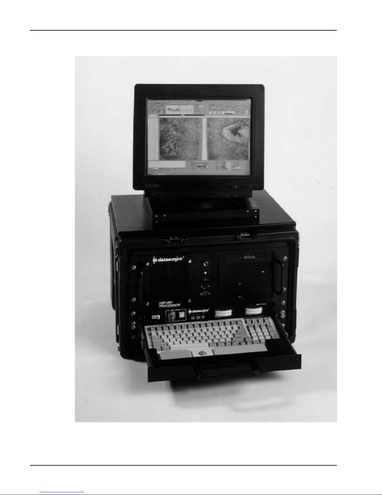
1-4 DATASONICS
Figure 1-1 SIP-150 Sonar Image Processor
Volume ISystem Manual June 1998
Page 19
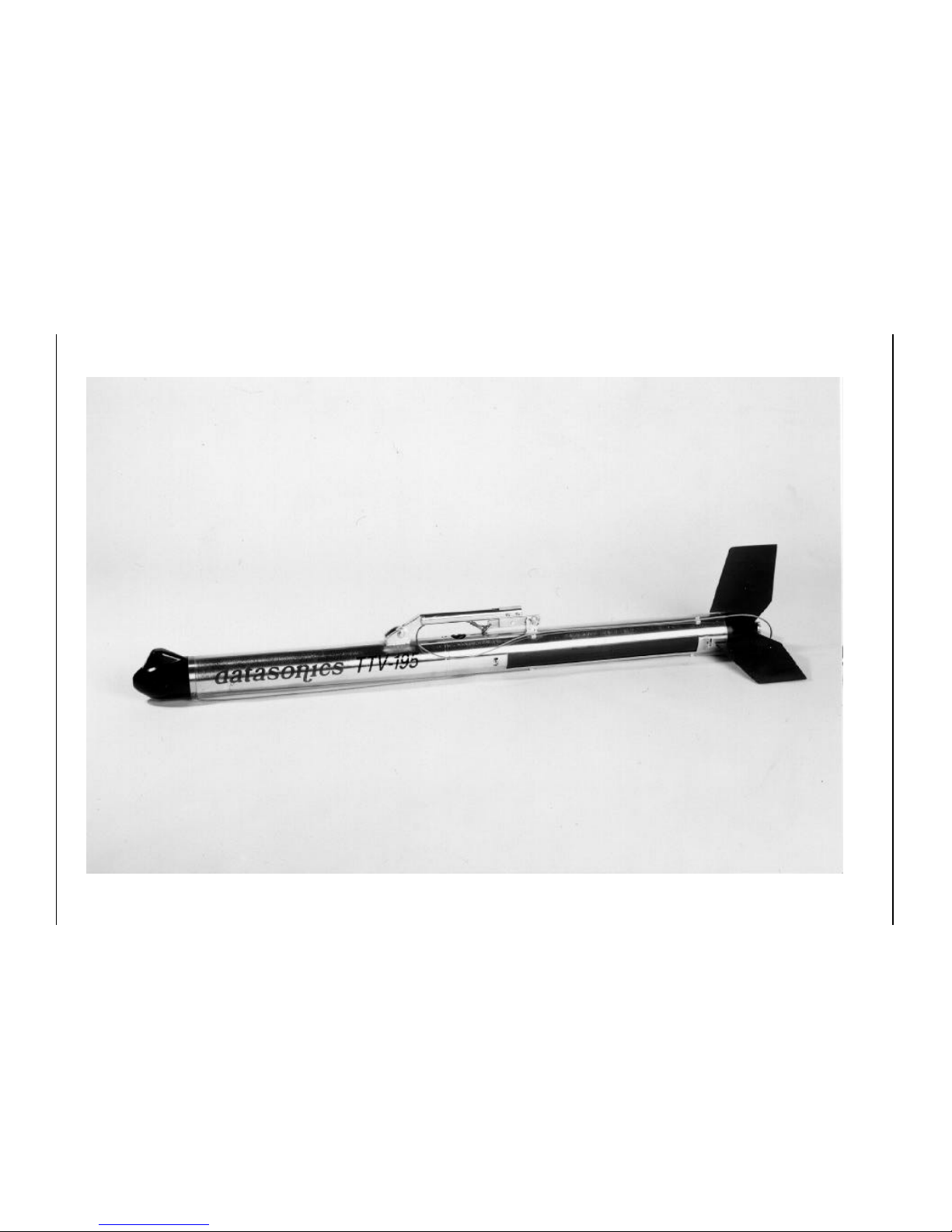
SIS-1500 Seafloor Imaging System 1-5
SECTION 1 SIS-1500 Overview Main System Components
Figure 1-2 TTV-195 Tow Vehicle
Page 20

1-6 DATASONICS
Advantages of Chirp Sonar
Chirp sonar technology employs swept FM transmitted signals along with
digital signal processing for matched-filter processing of reflected energy.
This delivers the following performance advantages:
a greater dynamic range is attained as long FM pulses provide an
additional 20 dB to 30 dB of dynamic range over conventional sidescan
sonar systems;
enhanced resolution is achieved with matched-filter processing, as
compared to systems using standard processing in the same frequency
band, by correlating the return signals with a replica of the outgoing
pulse;
transmitted waveforms are repeatable from pulse to pulse;
the temporal resolution is constant throughout the entire range;
the pulse characteristics are programmable, as the pulse length,
span of frequency sweep and phase/amplitude calibration of the transmit
waveform can be varied without hardware changes; and
the sidescan sonar data can be stored for off-line processing, on a
hard disk, a magneto-optical disk, or an Exabyte 8 mm cartridge tape.
SIP-150 Sonar Image Processor
The SIP-150 Sonar Image Processor comprises the SIP-150 Sonar Image
Processor Workstation, which includes the Chirpscan3 software, and the
Chirplink II Digital Multiplexer. Together the workstation, the Chirpscan3
software and the digital multiplexer serve to process, display and store the
sonar data, the tow vehicle status information and the sensor data that are
received from the tow vehicle. In addition, they monitor and control the tow
vehicle’s functions while sending commands and the sonar and responder
keys to the tow vehicle.
Volume ISystem Manual June 1998
Page 21

SIS-1500 Seafloor Imaging System 1-7
SIP-150 Sonar Image Processor Workstation
The SIP-150 Sonar Image Processor Workstation, which runs the Datasonics
Windows based Chirpscan3 software, serves as the operator interface for
monitoring and controlling the system. The workstation includes a Pentium
based processor, Windows 95/NT and the following components:
• 1280 X 1024 high resolution color monitor
• Dual channel digital signal processor
• Graphics processor
• Hard drive with a SCSI interface
• Optional magneto-optical drive or Exabyte 8 mm
cartridge tape drive
• CD ROM drive
• 1.44 megabyte floppy drive
• Drawer type integrated keyboard and pointing device
The workstation displays the port and starboard sidescan sonar data and the
pitch, roll, heading, course, and altitude data in separate display windows in
the Display area of the Main window. Also within the Main window is the
Parameter display, the Status display, the Sonar Controls box, and the
Auxiliary Controls box.
As the sonar data are received, the workstation processes the data using
matched-filter digital signal processing, applying continuous Short Time
Fourier Transforms (STFT) for each sweep or transmit cycle. In addition, the
full dynamic range of the processed data is recorded on digital storage media
while being displayed on a high resolution 1280 X 1024 monitor. An optional
printer or graphic recorder can be connected to print either the data currently
being recorded or previously recorded data.
In addition to the sonar data, the workstation integrates the tow vehicle status
information, the sensor data and the navigation data, if available, into the
sidescan sonar data records. The status information also includes various
tow vehicle hardware settings. The sensor data are input from the tow
vehicle’s pitch, roll, heading, and optional sensors, and the navigation data
are input from the ship’s navigation system.
SECTION 1 SIS-1500 Overview SIP-150 Sonar Image Processor
Page 22

1-8 DATASONICS
Chirpscan3 Software
The Chirpscan3 software has enabled the development of compact, low cost,
modular shipboard data acquisition and image processing systems.
Chirpscan3 supports the acquisition, processing and storage of multiple
channels of sidescan sonar data and also manages the acquisition and
storage of navigation, magnetic and environmental data. And as Chirpscan3
runs under Windows, it allows independent control of the processing. In
addition, a graphics engine drives the high resolution 1280 x 1024 color
monitor. The sonar records are stored on a hard disk, a magneto-optical disk,
or an Exabyte 8 mm cartridge tape.
Data Fusion and Storage
While sidescan sonar imagery are acquired and processed, other types of
data can be input to the workstation’s serial ports. For example, a navigation
device or an integrated navigation computer can be connected to a serial
port. Navigation data are merged into the standard data format in the
workstation and combined with the sonar data before being displayed and
recorded on the magneto-optical disk or the Exabyte 8 mm cartridge tape.
Although the sonar data can be saved to the workstation’s hard drive, the
higher density magneto-optical disk or tape cartridge is more appropriate for
storing the large files that are generated by the SIS-1500 Seafloor Imaging
System.
Realtime Display and Image Processing
Chirpscan3 runs under Windows 95/NT, which facilitates a standard and
familiar graphic user interface. The Windows environment also allows for
independent control of a number of data display windows. Several different
types of data display windows are available, each suited to a specific data
type. Windows also allows multiple applications of the software to run
simultaneously. This enables the viewing of a previously recorded file while
recording data in a new file.
The flexibility of the image processing features is a major advantage over
simple sonar video displays. These tools greatly enhance the power of the
workstation and the capabilities for manipulating and interpreting data.
Volume ISystem Manual June 1998
Page 23

SIS-1500 Seafloor Imaging System 1-9
Post-Processing of Data
Chirpscan3 enables both a record mode for data acquisition and real-time
image processing, and a playback mode for image processing and data
analysis after the sidescan sonar records have been collected and
processed. All the real-time image processing tools available with operation
in record mode are also available in playback mode.
Chirplink II Digital Multiplexer
The Chirplink II Digital Multiplexer is the communications interface between
the workstation and the tow vehicle. It provides full duplex communications
with the tow vehicle, allowing the workstation to send commands to the tow
vehicle while simultaneously receiving sonar data, tow vehicle status
information, and sensor data from the tow vehicle. In addition, the digital
multiplexer supplies power to the tow vehicle. Using a combination of
frequency division and time division multiplexing, the digital multiplexer
allows both the data and the power to be carried on a single coaxial cable,
which connects the digital multiplexer to the tow vehicle. Frequency division
multiplexing is used for transmitting all the downlink commands and uplink
vehicle status information and sensor data at a frequency of 9600 baud.
T1 telecommunications technology, an industry standard, is used for
transmitting all the sonar data at a data communications rate of
1.544 Mbits/sec. The digital multiplexer also contains the system’s main
power switch, and includes a front panel voltmeter and ammeter for
monitoring the power transmitted to the tow vehicle.
TTV-195 Tow Vehicle
The TTV-195 Tow Vehicle contains the sidescan sonar transducer arrays,
the sonar electronics and the standard pitch, roll and heading sensors.
Available optional sensors include temperature and pressure sensors, a
cesium magnetometer and a responder. The tow vehicle, which is 4.5 inches
in diameter and 70 inches long, is constructed of 316 stainless steel and is
specifically designed to operate at depths up to 1000 meters. The nose of the
tow vehicle contains the optional temperature sensor and the optional
responder transducer, where both are encapsulated in a single urethane
mold. The temperature sensor is in direct contact with the water at all times,
providing a fast thermal time constant and a means of correlating any
observed anomalies in the sonar data with changes in sound velocity that are
due to temperature gradients. The responder transducer is positioned to
SECTION 1 SIS-1500 Overview TTV-195 Tow Vehicle
Page 24

1-10 DATASONICS
provide the optimum beam pattern for tracking the tow vehicle with an
acoustic positioning system. The optional pressure sensor is contained within
the end cap and is exposed to ambient pressure through a port on the rim of
the end cap.
The nose is attached to the forward end of a pressure housing, the
electronics housing, which contains the sonar electronics. An end cap both
seals the opposite end of the housing and attaches to another housing, the
sonar transducer housing, which is free flooding and contains the sonar
transducers. The nose and end cap are secured to the electronics housing
with a closure bolt in the nose. The electronics housing also contains the
vehicle’s tow point, and the sonar transducer housing contains the vehicle’s
tail fin.
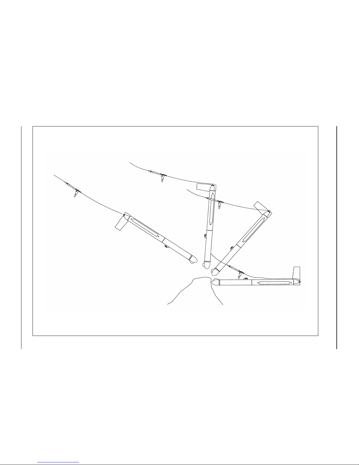
The tow vehicle’s towing arm, which is designed for rapid attachment and
detachment, contains a shear pin release mechanism, which is designed to
cause the towing arm to break away from the tow point should a collision
occur or should the tow vehicle become snagged. However, one end of a
recovery cable is attached to the towing arm. The cable runs back along the
top of the vehicle to its stern. Should an obstruction cause the tension on the
towing arm to exceed 200 lbs, the towing arm will break away and the tow
vehicle will cartwheel one-half of a revolution, with the nose moving
downward and then backward, clearing the tow vehicle from the obstruction.
This is shown in Figure 1-3. As the recovery cable remains attached, the tow
vehicle can be safely recovered. The tail fin will also break away should it
collide with an obstruction—and it is easily replaced.
Sidescan Sonar Transducer Arrays
The sidescan sonar, which operates in the 190 to 210 kHz band, utilizes two
transducer line arrays that are installed in the free flooding transducer
housing. The arrays are aligned end to end, with one along each side of the
tow vehicle. This arrangement provides a one-way horizontal beam width of
1° and a vertical beam width of 50°. In addition, the down-look angle of each
transducer array is adjustable from 0° to 20° in 10° increments.
Volume ISystem Manual June 1998
Page 25
SIS-1500 Seafloor Imaging System 1-11
SECTION 1 SIS-1500 Overview TTV-195 Tow Vehicle
Figure 1-3 TTV-195 Tow Vehicle Breaking Away from Obstruction
Page 26

1-12 DATASONICS
Sonar Electronics
Contained within the electronics housing in the tow vehicle is the sonar
electronics, which controls the tow vehicle’s functions, generates and
transmits the Chirp waveforms, and processes the received signals. Included
with the sonar electronics in the electronics housing are the pitch, roll, and
heading sensors. The sonar electronics receives power, downlink
commands, and the sonar and responder keys from the Chirplink II Digital
Multiplexer, and transmits the sonar data, the tow vehicle status information,
and the sensor data to the digital multiplexer.
Optional Sensors
Spare RS-232 and analog inputs are available for connecting optional
sensors and oceanographic instruments, including a temperature sensor, a
pressure sensor, and a cesium magnetometer. In addition, a responder input
is included, which allows for the installation of a responder for tow vehicle
positioning.
Chirp Technology
Chirp technology uses digitally produced linear FM acoustic transmissions to
produce high resolution images of seafloor contours. In all sonar systems,
higher frequency content is invariably associated with an increase in
resolution, and in the case of a sidescan sonar, a decrease in range. Chirp
technology, as implemented in the SIS-1500 Seafloor Imaging System,
reduces this trade-off, providing both high resolution and extended range.
Across-Track Resolution
The resolution of a sidescan sonar is measured by its ability to discern closely
spaced objects that lie in the direction that is 90 degrees to the path of the
tow vehicle. This resolution is referred to as the across-track resolution. A
sidescan sonar system with an across-track resolution of 10 cm will detect
individual objects that are at least 10 cm apart. Objects spaced closer than
10 cm will be resolved by the sonar as a single object. In a conventional
sidescan sonar system, the limit of its resolution is determined by the pulse
length of the transmitted waveform. In the SIS-1500 Seafloor Imaging
System, which is a Chirp sidescan sonar system, it is the bandwidth of the
transmitted pulse that sets the system's theoretical resolution. The theoretical
Volume ISystem Manual June 1998
Page 27

SIS-1500 Seafloor Imaging System 1-13
across-track resolution of a conventional system is calculated by multiplying
the length of the pulse by the speed of sound, and then dividing the product
by 2 to account for the pulse’s round trip.
across-track resolution = pulse length x speed of sound / 2
In comparison the pulse length equivalent of a de-Chirped swept frequency
pulse equals the inverse of the bandwidth.
pulse length = 1 / bandwidth
For example, the duration of a pulse with a bandwidth of 20 kHz, which is the
bandwidth of a system configured to operate between 190 and 210 kHz, is
approximately 50 µs (1/20000 Hz = 0.00005 sec). Travelling at about
1500 m/sec, the sound will traverse approximately 7.5 cm in 50 µs. Allowing
for the round trip, this results is a one-way distance of 3.75 cm, which is the
across-track resolution.
Along-Track Resolution
In addition to the frequency and bandwidth of the transmitted sonar beam,
which affect the across-track resolution, the horizontal width of the beam
affects the sidescan sonar’s resolution in the direction that is parallel to the
path of the tow vehicle. This resolution is referred to as the along-track
resolution. To attain a high along-track resolution, narrow beam widths are
required. However, narrow beams produce side lobes, which contain energy
that produces undesired echoes from reflections not located in the primary
beam. In conventional sidescan sonar systems resolution is lost due to the
presence of these echoes. With Chirp technology the side lobes are greatly
reduced through matched-filter correlation processing, which attenuates
echoes that do not correlate well with the transmitted pulse.
Signal-to-Noise Ratio
Another factor that affects the image quality is the signal-to-noise ratio. As the
transmitted pulse travels through the water, its amplitude becomes
attenuated and falls below the noise level. The matched-filter correlation
processing used in the SIS-1500 Seafloor Imaging System improves the
signal-to-noise ratio, and hence the quality of the sonar images.
SECTION 1 SIS-1500 Overview Chirp Technology
Page 28

1-14 DATASONICS
Chirp Pulse Transmission and Reception
The sequence of steps in the transmission and reception of the Chirp pulses
are summarized as follows:
1. A linear FM pulse is generated at fixed intervals.
2. The signal is sent to power amplifiers that drive the two sidescan sonar
transducer arrays. The sidescan’s port transducer array sweeps from a
low to a high frequency, while the starboard array sweeps from a high to
a low frequency. The counter-directional sweeps minimize cross-talk
between the sidescan channels.
3. The sidescan sonar transducer arrays transmit the pulse and the same
transducer arrays detect the reflected energy.
4. Reflections at the receiver array are amplified by a computer-controlled
amplifier and a user-programmable gain stage. In addition, the sidescan
receiver applies time varying gain to enhance attenuated signals
returning from greater distances.
5. The received sonar signals are digitized with a 16-bit A/D converter.
6. On the surface a dual channel digital signal processor in the workstation
de-Chirps (compresses the FM reflections using the matched-filter) the
return signals from the sidescan sonar. This correlates the received
reflections with a compensated replica of the outgoing pulse. Signals that
do not resemble the outgoing pulses are attenuated by this type of
processing. Compressed returns are further processed to correct for
amplitude losses from attenuation and absorption by the water.
Volume ISystem Manual June 1998
Page 29

SIS-1500 Seafloor Imaging System 2-1
SECTION 2
Specifications
SECTION 2 Specifications
Page 30

2-2 DATASONICS
Volume ISystem Manual June 1998
Page 31

SIS-1500 Seafloor Imaging System 2-3
T
he information in this section encompasses the physical and
performance specifications of the SIS-1500 Seafloor Imaging
System, and includes the SIP-150 Sonar Image Processor and the
TTV-195 Tow Vehicle.
SIP-150 Sonar Image Processor
The SIP-150 Sonar Image Processor includes the SIP-150 Sonar Image
Processor Workstation and the Chirplink II Digital Multiplexer. And the
workstation includes the monitor, the integrated keyboard and pointing
device, and the Chirpscan3 software. The digital multiplexer performs all the
uplink and downlink communications with the tow vehicle and interfaces with
the workstation. Both the workstation and the digital multiplexer are housed
in the same standard 19" rack.
Physical Characteristics
Case size: 30.5 cm (12") high by 50.8 cm (20") wide by
45.7 cm (18") deep
Monitor size: 41.7 cm (16.4") high by 40.9 cm (16.1") wide
by 44.4 cm (17.5") deep (typical)
Case type: Splash and abrasion-resistant,
transportable Hardigg
Case weight: 30 lb (13.6 kilograms)
Monitor weight: 38 lb (16.7 kilograms)
Software
Application: Chirpscan
Operating system: Windows 95/NT
3
Computer
Host CPU: Pentium
I/O ports: 4 serial, 1 parallel, 1 SCSI
SECTION 2 Specifications SIP-150 Sonar Image Processor
Page 32

2-4 DATASONICS
Memory: 32MB RAM
Digital signal processors: Dual TMS320C40, 60 MHz digital signal
processor
Graphics processor: 128-bit graphics engine
Standard data storage: Internal hard drive with SCSI interface
3.5" floppy drive
Optional data storage: Magneto-optical drive
Exabyte 8 mm cartridge tape drive
Power supply: 300 Watt
Display
Screen size: 17 inches
Screen resolution: 1280 x 1024
Power Requirements
Power input: 100 - 125 VAC or 220 - 240 VAC,
50 - 60 Hz, 900 Watts
Input/Output
Printer: Digital thermal recorder
Operator: Integrated keyboard and pointing device
Tow vehicle: Uplink sonar data input
Vehicle status information input
Sensor data input
Downlink commands output
Sonar key output
Responder key output
Volume ISystem Manual June 1998
Page 33

SIS-1500 Seafloor Imaging System 2-5
External: Navigation input
Responder key input
Sonar key input
Other: SCSI for optional external storage devices
Output Power
Voltage: High voltage DC
Power output: 300 Watts nominal
Downlink Commands
Carrier frequency: 35 kHz
Allotted spectrum: 30 kHz to 40 kHz
Format: RS-232 ASCII, 9600 baud
Commands: Transmit repetition rate
Transmit pulse length
Port sidescan transmitter ON/OFF
Starboard sidescan transmitter ON/OFF
Port sidescan sonar receiver gain
Starboard sidescan sonar receiver gain
Diagnostics
Downlink Responder Key
Carrier frequency: 48.250 kHz
Format: Digital pulse
Downlink Sonar Key
Carrier frequency: 12.0625 kHz
Format: Digital pulse
SECTION 2 Specifications SIP-150 Sonar Image Processor
Page 34

2-6 DATASONICS
Uplink Vehicle Status and Sensor Data
Carrier frequency: 65 kHz
Allotted spectrum: 60 kHz to 70 kHz
Format: RS-232 ASCII, 9600 baud
Vehicle status: Heading, 0-360°
Pitch, +/- 20°, positive counterclockwise
Roll, +/- 20°, positive counterclockwise
Starboard sidescan receiver gain setting
Port sidescan receiver gain setting
Downlink command echo
Uplink checksum word
Sensor data (optional): Temperature sensor
Pressure sensor
Cesium magnetometer
Uplink Sonar Data
Allotted spectrum: 90 kHz and higher
Data rate: 1.544 Mbits/sec
Format: Industry-standard T1
Data: Port and starboard sidescan
TTV-195 Tow Vehicle
The TTV-195 Tow Vehicle connects to the SIP-150 Sonar Image Processor
through a coaxial cable. The tow vehicle contains the sonar electronics, the
sonar transducer arrays, and the optional sensors.
Physical Characteristics
Construction: 316 stainless steel
Dimensions: 11.4 cm (4.5") OD by 177.8 cm (70") long
Weight in air: 75 lb (34 kilograms)
Weight in water: 55 lb (25 kilograms), approximately
Volume ISystem Manual June 1998
Page 35

SIS-1500 Seafloor Imaging System 2-7
Tether system: Industry-standard armored coaxial tow
cable
Operating depth: 1000 meters
Towing speed: 1 to 8 knots operational
Input power: High voltage DC, 300 Watts nominal
Sidescan Sonar
Xmit/Receive transducers: One 6-element transducer array
Acoustic source level: +225 dB re 1 µPa @ 1 meter
Range: 25 to 500 meters each channel
Frequency range: Sweeps in the 190 kHz to 210 kHz band;
port and starboard sidescan sonar sweep
in opposite directions
Transducer radiation: 0.5° one-way horizontal, 50° vertical
Receiver gain: User adjustable from 0 to 21 dB in 3 dB
increments; time varied from -20 to 40 dB
Sensors
Pitch and roll: Range, ± 20°
Accuracy, ±0.2°
Resolution, 0.1°
Heading: Range, 0 - 360°
Accuracy, ±1° rms
Resolution, 0.1°
Optional sensors: Temperature sensor
Pressure sensor
Cesium Magnetometer
Responder
SECTION 2 Specifications TTV-195 Tow Vehicle
Page 36

2-8 DATASONICS
Volume ISystem Manual June 1998
Page 37

SIS-1500 Seafloor Imaging System 3-1
SECTION 3
Setup and Deployment
SECTION 3 Setup and Deployment
Page 38

3-2 DATASONICS
Volume ISystem Manual June 1998
Page 39

SIS-1500 Seafloor Imaging System 3-3
S
etting up the SIS-1500 Seafloor Imaging System begins with the
careful unpacking and inspection of the system components. Once
this is complete, the SIP-150 Sonar Image Processor is set up and
connected to the TTV-195 Tow Vehicle. The system is then activated,
Chirpscan3 is started, some configuration and predeployment checks are
made, and the tow vehicle is deployed. This section encompasses these
operations, describes the operator controls and indicators, and includes a
startup procedure for getting the system operational quickly.
NOTE Once the tow vehicle is deployed and the system is operating, refer
to the Chirpscan3 manual for detailed information on the operation of the
Chirpscan3 software.
Unpacking
The system hardware is shipped in three wooden boxes or optional, reusable
Hardigg cases, which allow the system to be transported many times. A
fourth box contains the deck cable, the software and the system
documentation. As the contents and number of boxes may vary, refer to the
packing list for detailed information. The four boxes contain the following
items:
Box #1
SIP-150 Sonar Image Processor
AC power cables (2)
Printer cable (with optional printer only)
SCSI cable (with optional external storage device only)
Box #2
Monitor
Monitor cable
AC power cable
SECTION 3 Setup and Deployment Unpacking
Page 40

3-4 DATASONICS
Box #3
TTV-195 Tow Vehicle
(5) tail fins
(1) spare shear pin
(1) 1/4” drive palm ratchet extension
Box #4
75 meter Kevlar reinforced deck cable
Volume I, SIS-1500 system manual
Volume II, Chirpscan3 manual
Volume III, Chirpscan3 disks
Manuals for optional components
MO disks (2, with magneto-optical drive option only)
Before opening the boxes, inspect them for any signs of external damage.
Immediately report any damage to Datasonics and to the freight carrier.
Perform the steps below to remove the items from the boxes.
1. Carefully remove the SIP-150 Sonar Image Processor from its box, and
then remove the cables from the compartment that is at the bottom of the
box.
2. Carefully remove the monitor from its box along with the monitor cable
and the AC power cable.
3. Remove the tiedown straps that secure the TTV-195 Tow Vehicle and
remove the tow vehicle from its box
4. Remove the 75 meter Kevlar reinforced deck cable, the manuals and
disks, and any optional equipment.
5. After removing the contents, inspect the items for any damage before
setting up. Do not operate or deploy any equipment that appears to have
been damaged in shipping.
Volume ISystem Manual June 1998
Page 41
SIS-1500 Seafloor Imaging System 3-5
Processor Setup
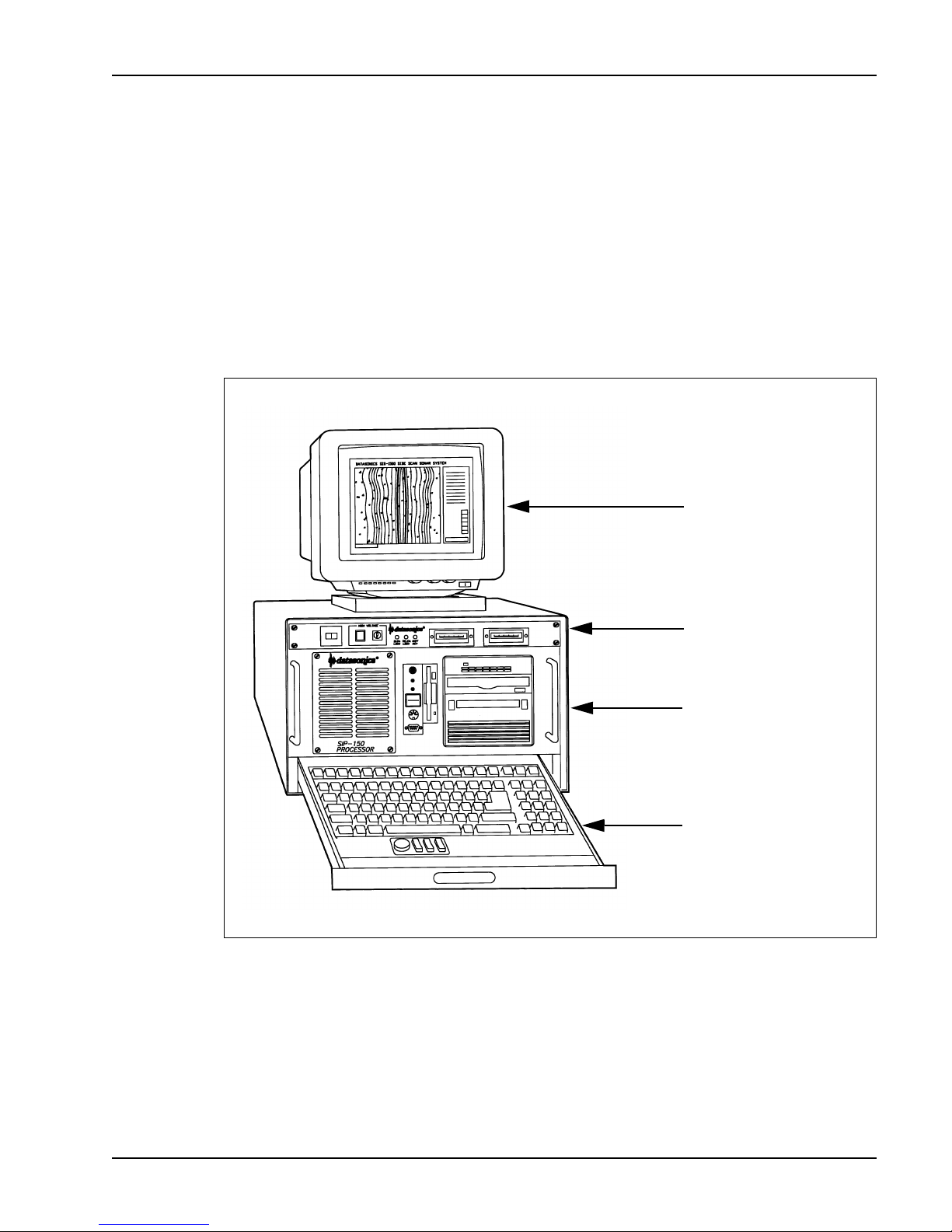
Determine where the SIP-150 Sonar Image Processor will be set up.
Figure 3-1 shows the recommended setup configuration. Secure the
processor in place, using tie-downs if necessary, near a 100 - 125 VAC or
220 - 240 VAC, 50 - 60 Hz power source. Be sure the back of the processor
is accessible for connecting the cables. Slide the monitor into the channel on
top of the processor, making sure that the swivel base is securely attached to
the monitor. Then pull out the drawer type keyboard.
MONITOR
CHIRPLINK II DIGITAL
MULTIPLEXER
SIP-150 SONAR IMAGE
PROCESSOR
WORKSTATION
DRAWER TYPE
KEYBOARD WITH
POINTING DEVICE
Figure 3-1 SIP-150 Sonar Image Processor Recommended Setup
SECTION 3 Setup and Deployment Processor Setup
Page 42

3-6 DATASONICS
Processor Hardware Connections
Once the SIP-150 Sonar Image Processor is secured and the associated
cables and devices are connected, it is ready to be connected to the
TTV-195 Tow Vehicle. All the connections are made on the back of the
processor, and all the cables that connect between the SIP-150 Image
Processor Workstation and the Chirplink II Digital Multiplexer are factory
installed.
Workstation Connections
The SIP-150 Sonar Image Processor Workstation connectors and their
description and use are listed below.
Connector Description And Use
PRINTER: DB-25S parallel port connector that
connects to the optional printer.
KEYBOARD: 5-PIN DIN keyboard connector that
connects to the keyboard.
MOUSE: 9-PIN DB connector that connects to the
keyboard pointing device.
SCSI: Optional SCSI connector that connects to
an optional external storage device.
NAV: DB-9P serial port connector that
connects to the navigation system and is
used to input any standard NEMA0183
string.
TELEM: DB-9P serial port connector that
connects to the TELEM connector on the
multiplexer and is used to output tow
vehicle commands to the multiplexer and
input tow vehicle status information and
sensor data from the multiplexer.
AUX: DB-9P serial port connector that is
VIDEO: DB-15 connector that connects to the
Volume ISystem Manual June 1998
available as a spare.
workstation monitor.
Page 43

SIS-1500 Seafloor Imaging System 3-7
SYNCH IN: DB-15 connector that connects to the
SYNCH OUT connector on the
workstation and is used to input the sonar
data and the clock signals for
synchronizing the sonar data.
VAC IN: AC power input connector that connects
to the AC power source.
VAC OUT: AC power output connector that connects
to the monitor.
Digital Multiplexer Connections
The Chirplink II Digital Multiplexer connectors and their description and use
are listed below.
Connector Description And Use
DECK CABLE: UHF connector that connects to the
75 meter Kevlar reinforced deck cable
and is used to input sonar data, tow
vehicle status information and sensor
data from the tow vehicle and to output
power, commands, and the sonar and
responder keys to the tow vehicle.
EXT KEY IN: BNC connector that connects to an
external source and is used to key the
sidescan sonar from the external source
when a 0-5 volt, 100 µsec minimum pulse
width signal is input. External Trigger
must also be selected through the
Chirpscan3 software.
KEY OUT: BNC connector that connects to an
external source and is used to key the
external source. The output pulse is a
0-5 volt, 100 µsec wide pulse that occurs
at the start of each ping cycle.
SECTION 3 Setup and Deployment Processor Hardware Connections
Page 44

3-8 DATASONICS
RESP KEY IN: BNC connector that connects to an
external responder trigger source and is
used to key the optional transponder
when a 0-5 volt, 100 µsec minimum pulse
width signal is input.
SYNCH OUT: DB-15 connector that connects to the
SYNCH IN connector on the processor
and is used to output the sonar data and
the clock signals for synchronizing the
sonar data.
TELEM: DB-9P serial port connector that
connects to the TELEM connector on the
workstation and is used to input tow
vehicle commands from the workstation
and output tow vehicle status information
and sensor data to the workstation.
AUX: DB-9P serial port connector that is used
for diagnostics and is not available to the
user.
VAC IN: AC power input connector that connects
to the AC power source.
Connecting the Processor
Follow the steps listed below to make the connections to the SIP-150 Sonar
Image Processor. All the cables that connect between the workstation and
the multiplexer are factory installed; however, they are included in the steps
listed below should they be required to be reconnected.
WARNING Before making any connections to the processor, be sure the
high voltage power supply is off by verifying that the POWER switch and
the HIGH VOLTAGE key switch on the front panel of the digital multiplexer
are off. Refer to Digital Multiplexer Operator Functions on page 3-11 for a
description of the digital multiplexer front panel controls and indicators.
Volume ISystem Manual June 1998
Page 45

SIS-1500 Seafloor Imaging System 3-9
1. Connect the monitor cable to the VIDEO connector on the workstation
and to the monitor.
2. Be sure the monitor power switch is off and connect the monitor
AC power cable to the VAC power output connector on the workstation.
3. Connect an AC power cable to the VAC IN connector on the workstation
and to the 100 - 125 VAC or 220 - 240 VAC, 50 - 60 Hz power source.
4. Connect an AC power cable to the VAC IN connector on the multiplexer
and to the 100 - 125 VAC or 220 - 240 VAC, 50 - 60 Hz power source.
NOTE The SIP-150 Sonar Image Processor is autosensing and does not
require special switch settings for 110 VAC or 220 VAC operation.
The following connections are factory installed; however, should they be
disconnected, reconnect them as follows:
1. Connect the keyboard to the KEYBOARD and MOUSE connectors.
2. Connect DATA IN on the workstation to DATA OUT on the multiplexer.
3. Connect CLOCK IN on the workstation to CLOCK OUT on the
multiplexer.
4. Connect TELEM on the workstation to TELEM on the multiplexer.
The following connections are optional:
1. Connect any external SCSI storage devices to the SCSI connector on
the workstation.
2. Connect the printer cable to the PRINTER connector on the workstation.
3. Connect the navigation output from the shipboard navigation system to
NAV on the workstation.
4. If an external source is to provide the responder key, connect the
source’s responder key output to RESP KEY IN on the digital multiplexer.
5. If an external source is to provide the sonar key, connect the source’s
key output to EXT KEY IN on the multiplexer.
6. If an external source is to be keyed by the sonar key, connect the
source’s key input to KEY OUT on the multiplexer.
SECTION 3 Setup and Deployment Processor Hardware Connections
Page 46

3-10 DATASONICS
Processor Operator Functions
Although Chirpscan3 provides most of the operator functions, there are
additional hardware functions that are accessible on the front panel of the
SIP-150 Sonar Image Processor, and they should be understood before
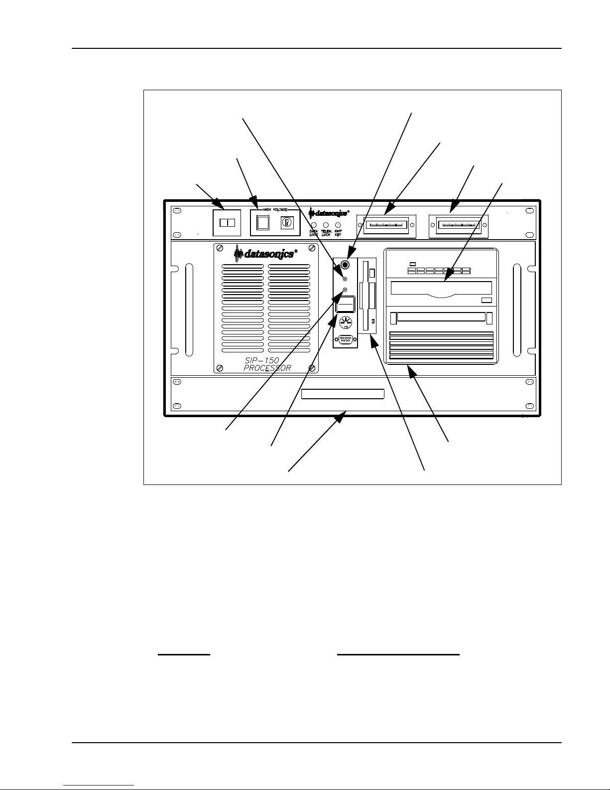
turning on and operating the system. They include the system operating
controls, indicators and storage devices, which are shown in Figure 3-2.
Workstation Operator Functions
The SIP-150 Sonar Image Processor Workstation operator functions and
their description and use are listed below:
Function Description And Use
HARD DRIVE LED: A red indicator that is illuminated when
the workstation is accessing the hard
drive.
RESET switch: A push button switch that resets the
workstation.
POWER switch: A rocker switch that turns the workstation
on or off. The workstation turns on when
“I” is pressed, and off when “O” is
pressed.
POWER LED: A green indicator that is illuminated when
the workstation is on.
3.5” Floppy drive: Accepts 3.5" floppy diskettes for alternate
boot-up, loading programs and files, and
making backup copies. The drive is
recognized as the A drive.
Magneto-optical drive: A device that uses optical read/write
disks for recording and playing back
data. (optional)
Exabyte drive: A device that uses magnetic tape
cartridges for recording and playing back
data. (optional)
CD-ROM drive: Optical read only disk for loading
Volume ISystem Manual June 1998
programs and data.
Page 47
SIS-1500 Seafloor Imaging System 3-11
HARD DRIVE LED
HIGH VOLTAGE
KEY SWITCH
AND INDICATOR
ON/OFF
SWITCH
RESET SWITCH
VOLTS METER
AMPS METER
CD-ROM
POWER LED
POWER SWITCH
KEYBOARD/
POINTING DEVICE
MAGNETO-OPTICAL
OR EXABYTE DRIVE
3.5” FLOPPY DRIVE
Figure 3-2 SIP-150 Sonar Image Processor Operator Functions
Keyboard/pointing device: A pull-out keyboard and pointing device
for entering commands.
Digital Multiplexer Operator Functions
The Chirplink II Digital Multiplexer operator functions and their description
and use are listed below.
Function Description And Use
ON/OFF switch: A circuit breaker/switch that turns the
digital multiplexer on or off. An indicator
in the switch is illuminated when on.
SECTION 3 Setup and Deployment Processor Operator Functions
Page 48

3-12 DATASONICS
HIGH VOLTAGE key switch: A key switch that turns the high voltage
power supply in the digital multiplexer on
or off. The key switch is on when it is in
the horizontal position and off when it is in
the vertical position. The high voltage
power supply is off and the key switch is
locked when the key is removed.
HIGH VOLTAGE indicator: A yellow indicator that is illuminated
when the high voltage power supply is
on. The indicator is on when both the
ON/OFF switch and the HIGH VOLTAGE
key switch on the digital multiplexer are
on.
VOLTS meter: An analog meter that Indicates the
voltage in volts being transmitted to the
tow vehicle from the digital multiplexer.
AMPS meter: An analog meter that indicates the
current in amps being transmitted to the
tow vehicle from the digital multiplexer.
DATA LOCK LED: A green indicator that flashes when the
sonar data link is being established and is
illuminated continuously when the link is
established.
TELEM LOCK LED: A green indicator that flashes when both
the uplink and downlink data telemetry is
being established and is illuminated
continuously when the link is established.
XMIT KEY LED: A red indicator that flashes once every
time a sonar key is output to the tow
vehicle.
Volume ISystem Manual June 1998
Page 49
SIS-1500 Seafloor Imaging System 3-13
Tow Vehicle Setup
The setting up of the TTV-195 Tow Vehicle encompasses the installation of
the tail fins, the connection of the SIP-150 Sonar Image Processor, and the
adjustment of the down-look angle of the transducer arrays.
Installing the Tail Fins
The tow vehicle requires the installation of three tail fins. Each fin is installed
in a separate slot at the aft end of the tow vehicle. Follow the steps listed
below to install the tail fins.
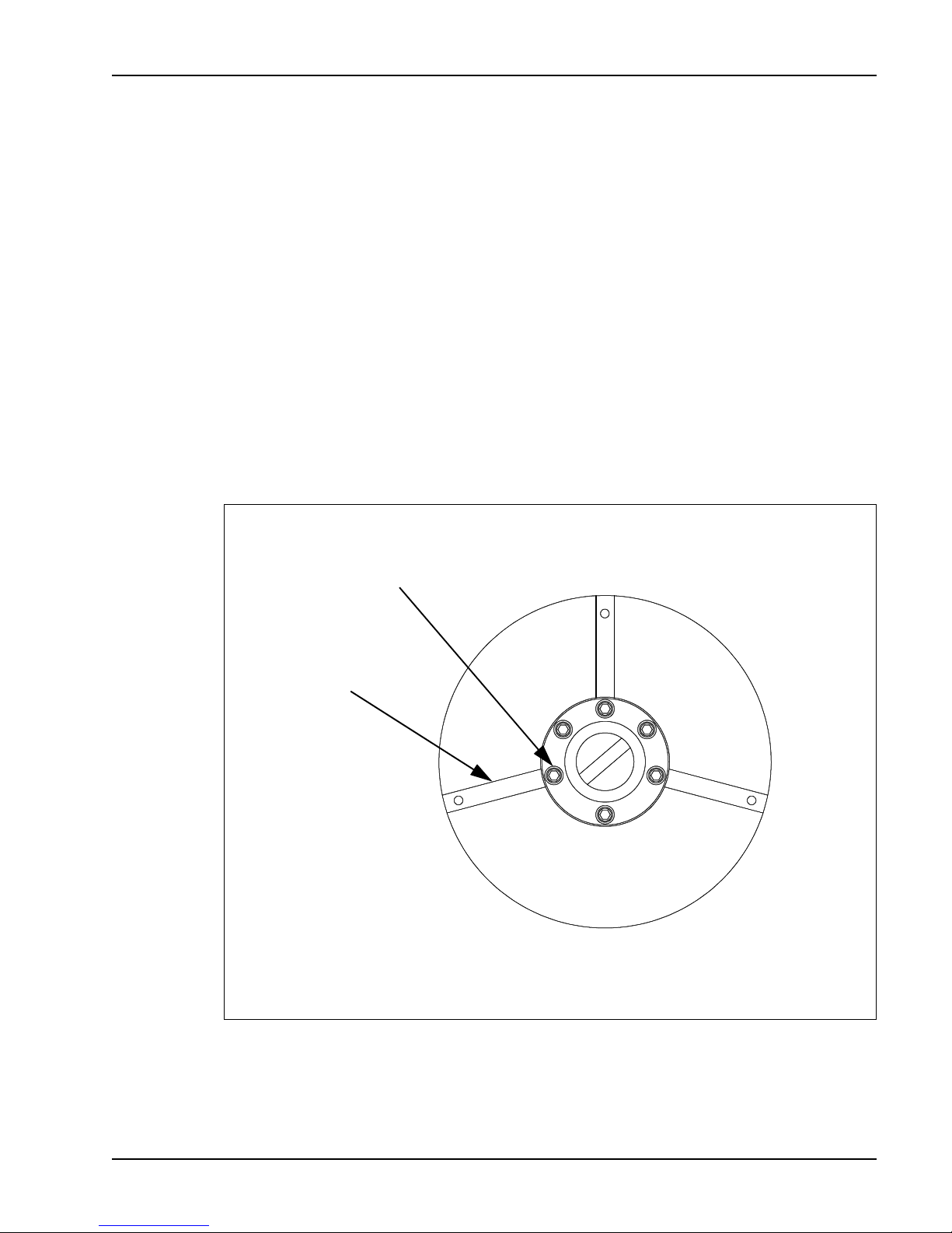
1. Refer to Figure 3-3 and loosen the three socket head retaining screws
that are used to secure the tail fins to the tow vehicle. Do not loosen the
other three screws.
SOCKET HEAD RETAINING
SCREW (3)
TAIL FIN
SLOT (3)
Figure 3-3 Tow Vehicle Tail Fin Retaining Screw Locations
SECTION 3 Setup and Deployment Tow Vehicle Setup
Page 50
3-14 DATASONICS
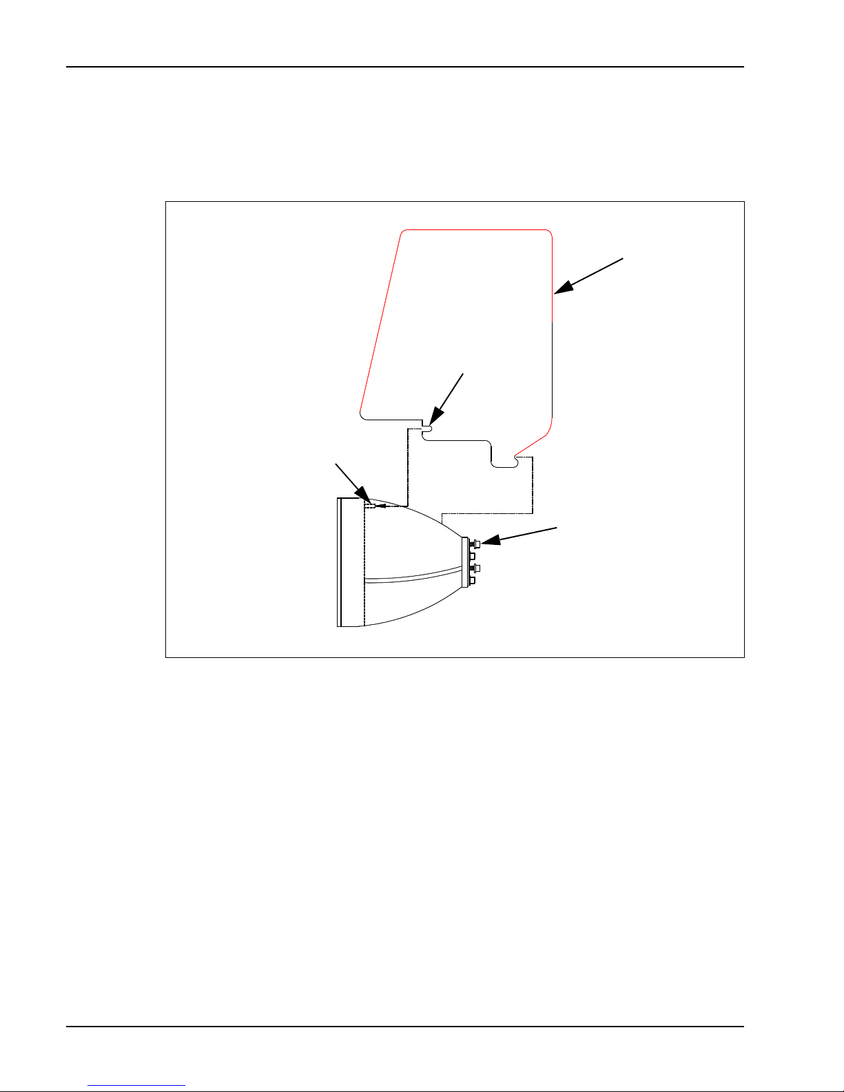
2. Refer to Figure 3-4 and position a tail fin as shown. Then carefully slide it
into one of the three available slots, pushing it into the slot until the notch
at the bottom of the tail fin engages with the stud at the bottom of the slot.
TAIL FIN (3)
SLOT IN
TAIL FIN
STUD IN BOTTOM
OF TOW VEHICLE
SLOT (3)
SOCKET HEAD SCREW
RESTS AGAINST TAIL
FIN (3)
Figure 3-4 Installing the Tow Vehicle Tail Fins
3. Tighten the corresponding socket head screw. Do not overtighten.
4. Repeat Steps 2 and 3 for the remaining two tail fins.
Volume ISystem Manual June 1998
Page 51
SIS-1500 Seafloor Imaging System 3-15
Connecting the Tow Vehicle
One end of the tow cable connects to the Chirplink II Digital Multiplexer, and
the other end connects both electrically and mechanically to the tow vehicle.
Follow the steps listed below to make the connections.
1. Connect the 75 meter Kevlar reinforced deck cable UHF connector to the
DECK CABLE connector on the digital multiplexer and the other end to
the slip ring assembly of a storage winch containing armored tow cable.
WARNING Do not use the deck cable to hoist or tow the tow vehicle.
Although the cable is Kevlar reinforced and has a strength member, it is not
to be used for towing.
2. Place the tow vehicle near its launching point.
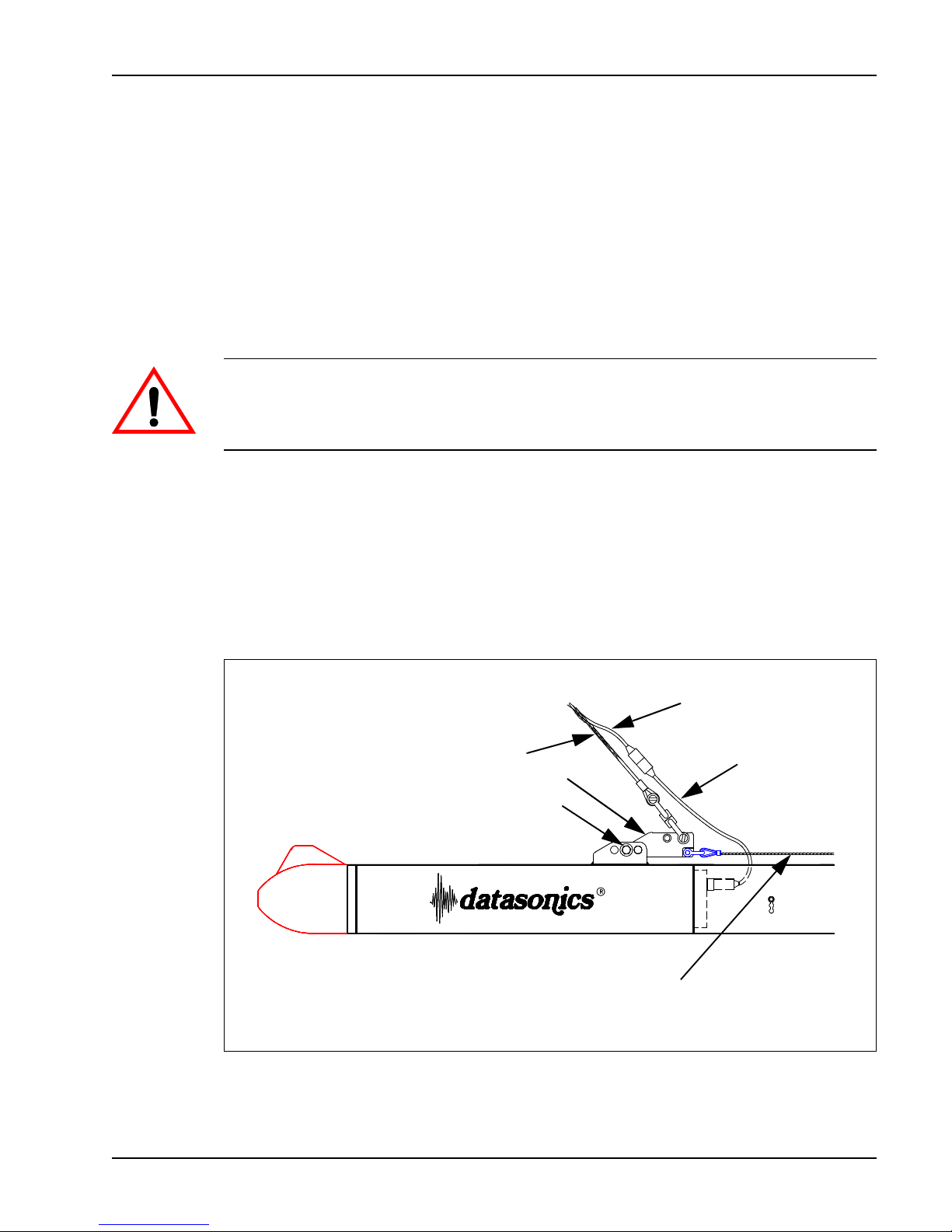
3. Connect the tow cable pigtail to the tow vehicle cable pigtail as shown in
Figure 3-5.
4. Attach the tow cable to the towing arm as shown.
5. Verify that the safety cable is secure.
TOW CABLE PIGTAIL
TOW CABLE
TOWING ARM
SHEAR PIN
SAFETY CABLE
TOW VEHICLE
CABLE PIGTAIL
Figure 3-5 Tow Vehicle Connections
SECTION 3 Setup and Deployment Tow Vehicle Setup
Page 52
3-16 DATASONICS
Adjusting the Down-Look Angle
The down-look angle of the port and starboard transducer arrays can be
adjusted from 0° to 20° in 10° increments. Perform the steps listed below to
adjust the angle.
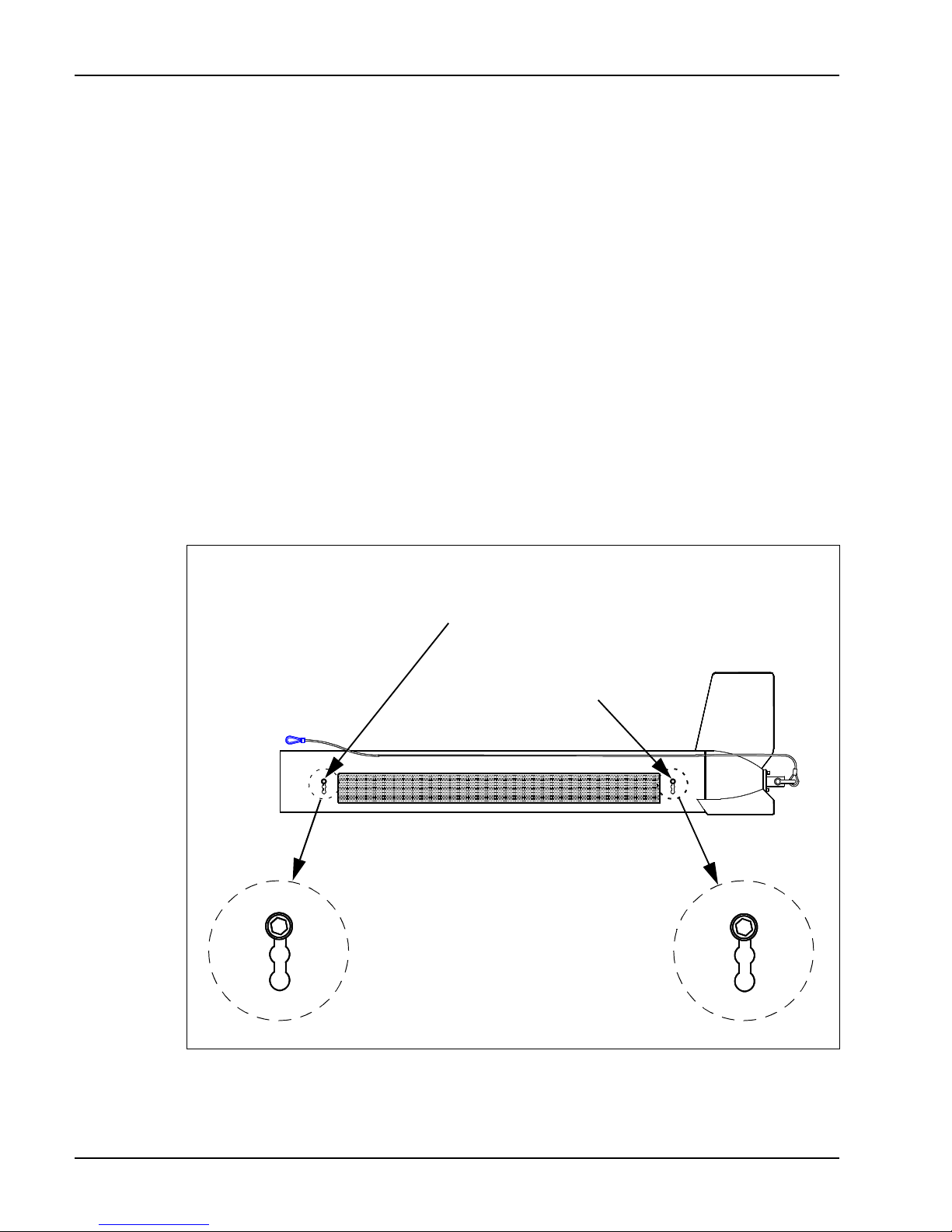
1. Locate the forward and aft down-look angle adjusting screws shown in
Figure 3-6.
2. Loosen each screw until the screw shoulder is free of the housing.
3. Grab each screw simultaneously, and then move the screws into the
required, corresponding notches.
The notch closest to the top of the tow vehicle is the 0° angle; the middle
notch, the 10° angle; and the notch closest to the bottom of the tow
vehicle, the 20° angle.
4. Retighten both screws.
FORWARD DOWN-LOOK
ANGLE ADJUSTING SCREW
AFT DOWN-LOOK ANGLE
ADJUSTING SCREW
Figure 3-6 Transducer Array Down-Look Angle Adjustment
Volume ISystem Manual June 1998
Page 53

SIS-1500 Seafloor Imaging System 3-17
System Startup
After all the connections have been made, the processor is ready to be turned
on and the Windows operating system and Chirpscan3 started. Once
Chirpscan3 is operational, some system parameters may need to be
configured, after which the tow vehicle can be activated.
NOTE Chirpscan3 operates under Windows 95/NT. If required, refer to a
Windows 95/NT user’s guide before proceeding.
Starting Chirpscan
3
Perform the steps listed below to turn on the workstation, to start Windows,
and to start Chirpscan3. Many of the tasks that are performed in Windows call
for the use of the pointing device. Unless otherwise stated it is the left button
of the pointing device that is pressed when the instructions call for “clicking”
in a window, “double clicking” an icon, or choosing a menu item.
WARNING Be sure the high voltage power supply is off by verifying that
the POWER switch and the HIGH VOLTAGE key switch on the front panel of
the digital multiplexer are off. Refer to Digital Multiplexer Operator
Functions on page 3-11 for a description of the digital multiplexer front
panel controls and indicators.
1. Turn on any optional external devices such as SCSI storage devices and
printers.
2. Turn on the monitor.
3. Turn on the workstation by pressing “I” on the POWER switch. The
POWER LED will light, and the HARD DRIVE LED will flash as the
workstation’s internal hard drive is accessed.
After the workstation has booted up, the Windows desktop opens.
4. Double-click the Chirpscan3 icon ( ) on the desktop to choose it.
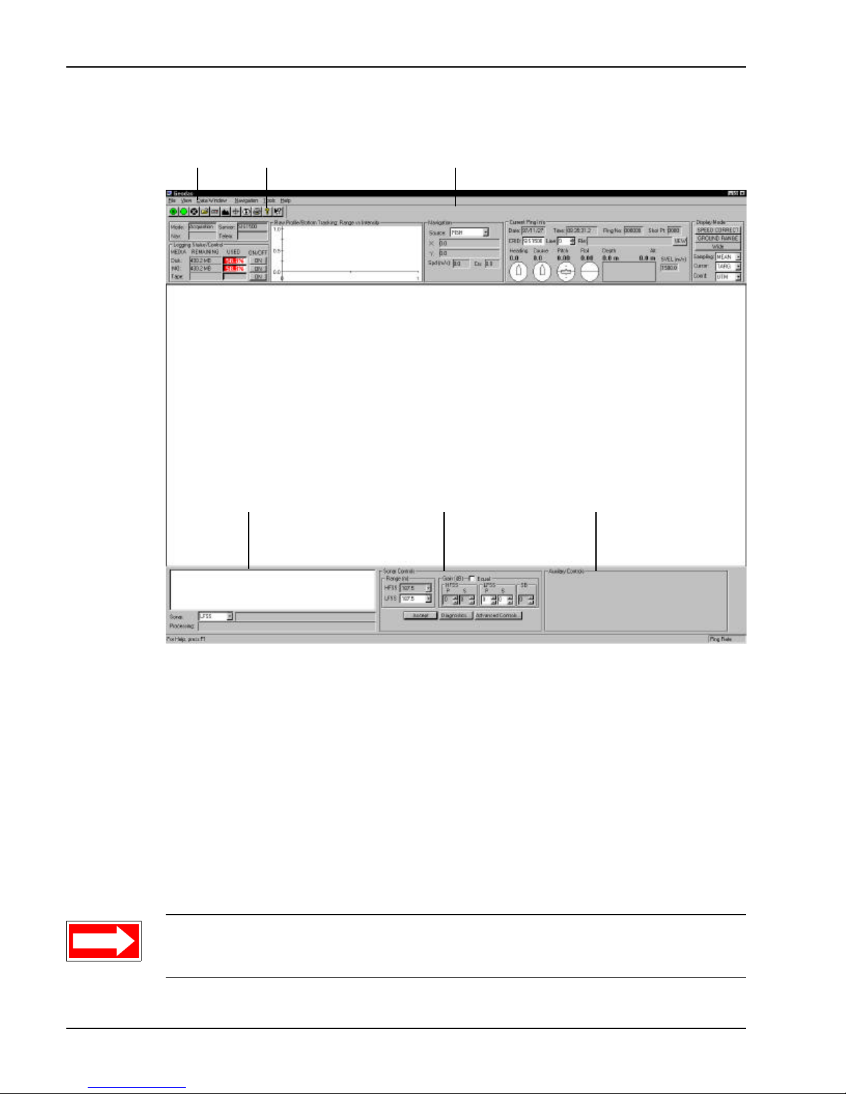
Chirpscan3 starts and the Main window shown in Figure 3-7 opens. The Main
window includes five main components: the Display area, the Parameters
display, the Status display, the Sonar Controls box, and the Auxiliary Controls
box. The Main window also includes a Quick-Access bar and a Menu bar.
SECTION 3 Setup and Deployment System Startup
Page 54
3-18 DATASONICS
Menu bar
Status display
Quick-Access bar
Parameters display
Display area
Sonar Controls box Auxiliary Controls box
Figure 3-7 The Main Window
Parameter Settings
If not already done so during prior uses of the system, it may be necessary to
verify or change the navigation, sonar, and display parameter settings. In
addition, settings that are changed can be made the new default settings. The
settings can also be saved, allowing many different settings to be individually
configured and recalled as desired. The parameter settings are configured in
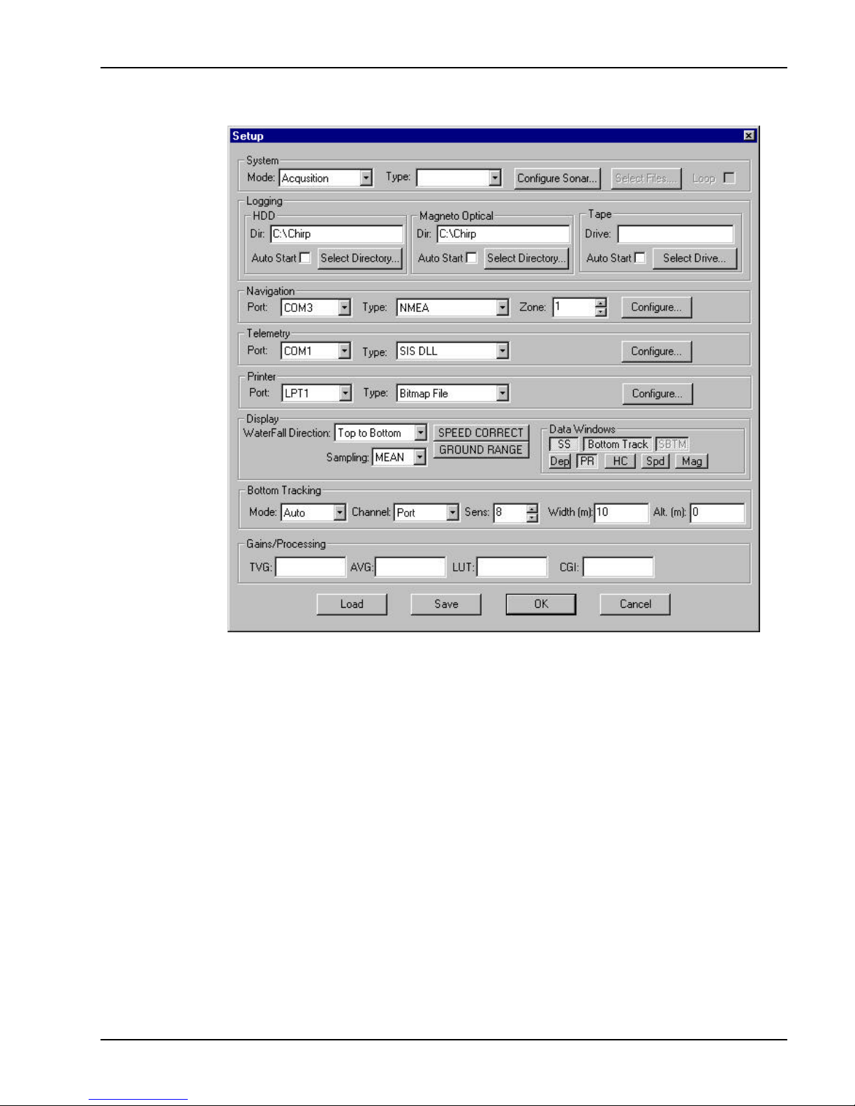
the Setup dialog box shown in Figure 3-8. To open the Setup dialog box,
select File from the menu bar, and then choose Setup.
NOTE For a complete description of all the settings in the Setup dialog box,
refer to the Chirpscan3 manual.
Volume ISystem Manual June 1998
Page 55
SIS-1500 Seafloor Imaging System 3-19
Figure 3-8 The Setup Dialog Box
Configuring the Navigation Parameter Settings
If a shipboard navigation system is or will be connected to the SIP-150 Sonar
Image Processor, the navigation parameter settings should be verified or
reconfigured as necessary. The processor accepts any NEMA0183 string
that is input from the external navigation system to the COM3 port of the
workstation. The navigation parameter settings are entered in the Navigation
area of the Setup dialog box.
To verify or reconfigure the navigation parameter settings:
1. Select File from the menu bar, and then choose Setup. The Setup dialog
box shown in Figure 3-8 opens.
2. In the Navigation area of the Setup dialog box click the down arrow in the
Port drop-down list box. A list of available communications ports opens.
SECTION 3 Setup and Deployment System Startup
Page 56
3-20 DATASONICS
3. Select COM3 from the Port drop-down list box.
4. Select NEMA from the Type drop-down list box.
5. Select 1 from the Zone drop-down list box.
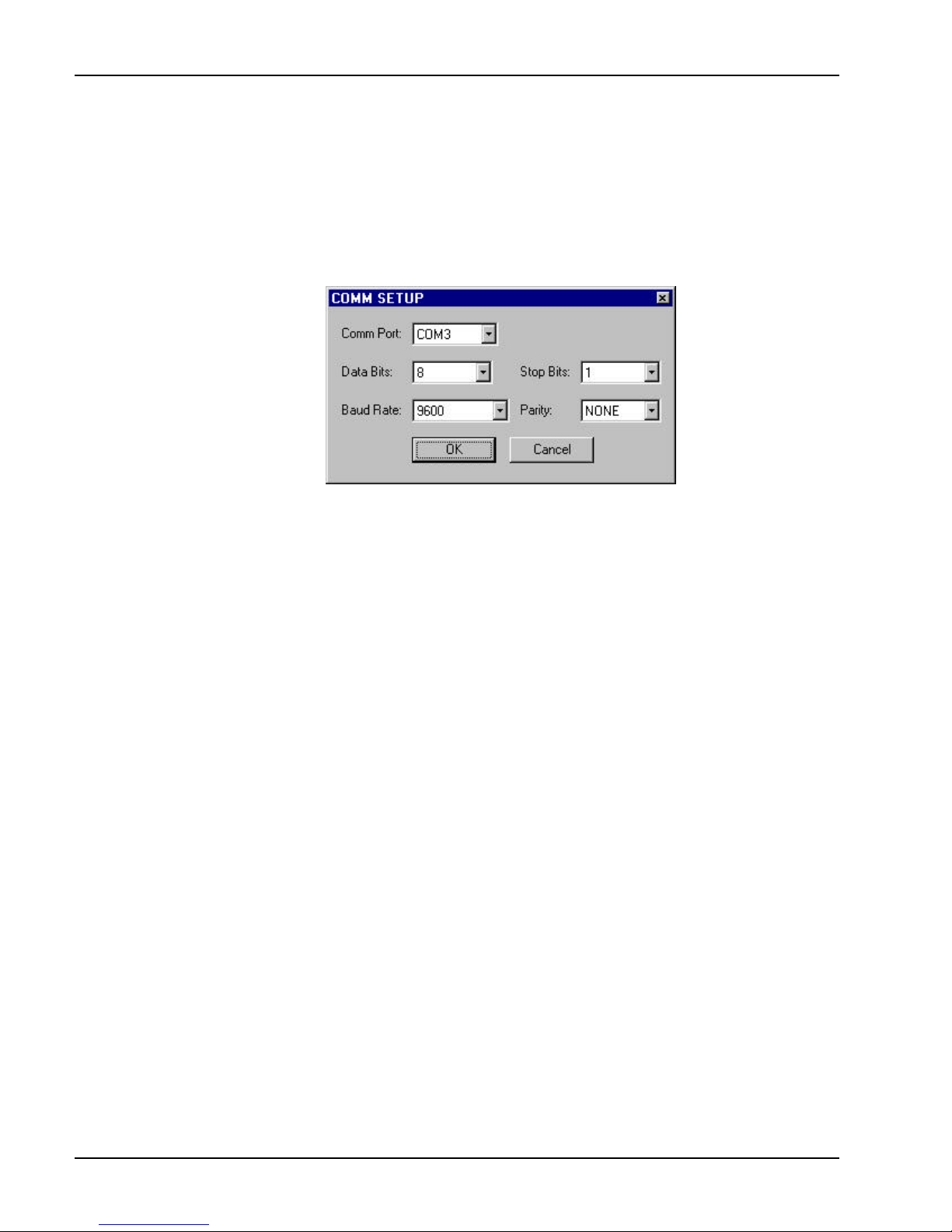
6. Click Configure. The Comm Setup dialog box shown in Figure 3-9 opens.
Figure 3-9 The Comm Setup Dialog Box
The Comm Setup dialog box contains five drop-down list boxes: Comm Port,
Data Bits, Baud Rate, Stop Bits, and Parity. The Comm Port box should
already be set to COM3 from Step 3. Before proceeding with the steps listed
below, determine the navigation system’s four communications parameters:
number of data bits, baud rate, number of stop bits, and parity.
7. Select the number of data bits from the Data Bits drop-down list box.
8. Select the baud rate from the Baud Rate drop-down list box.
9. Select the number of stop bits from the Stop Bits drop-down list box.
10. Select the parity from the Parity drop-down list box.
11. Click OK to close the Comm Setup dialog box and save the settings.
12. In the Setup dialog box click OK to close the Setup dialog box and save
the settings as the default settings, or click Cancel to close the dialog
box without saving the settings as the default settings.
Configuring the Sonar Parameter Settings
The sonar parameter settings should be verified or reconfigured as
necessary. There are three sonar parameter settings: range, separate port
and starboard receiver gains, and separate port and starboard power on and
off settings.
Volume ISystem Manual June 1998
Page 57
SIS-1500 Seafloor Imaging System 3-21
To verify or reconfigure the sonar parameter settings:
1. Select File from the menu bar, and then choose Setup. The Setup dialog
box shown in Figure 3-8 on page 3-19 opens.
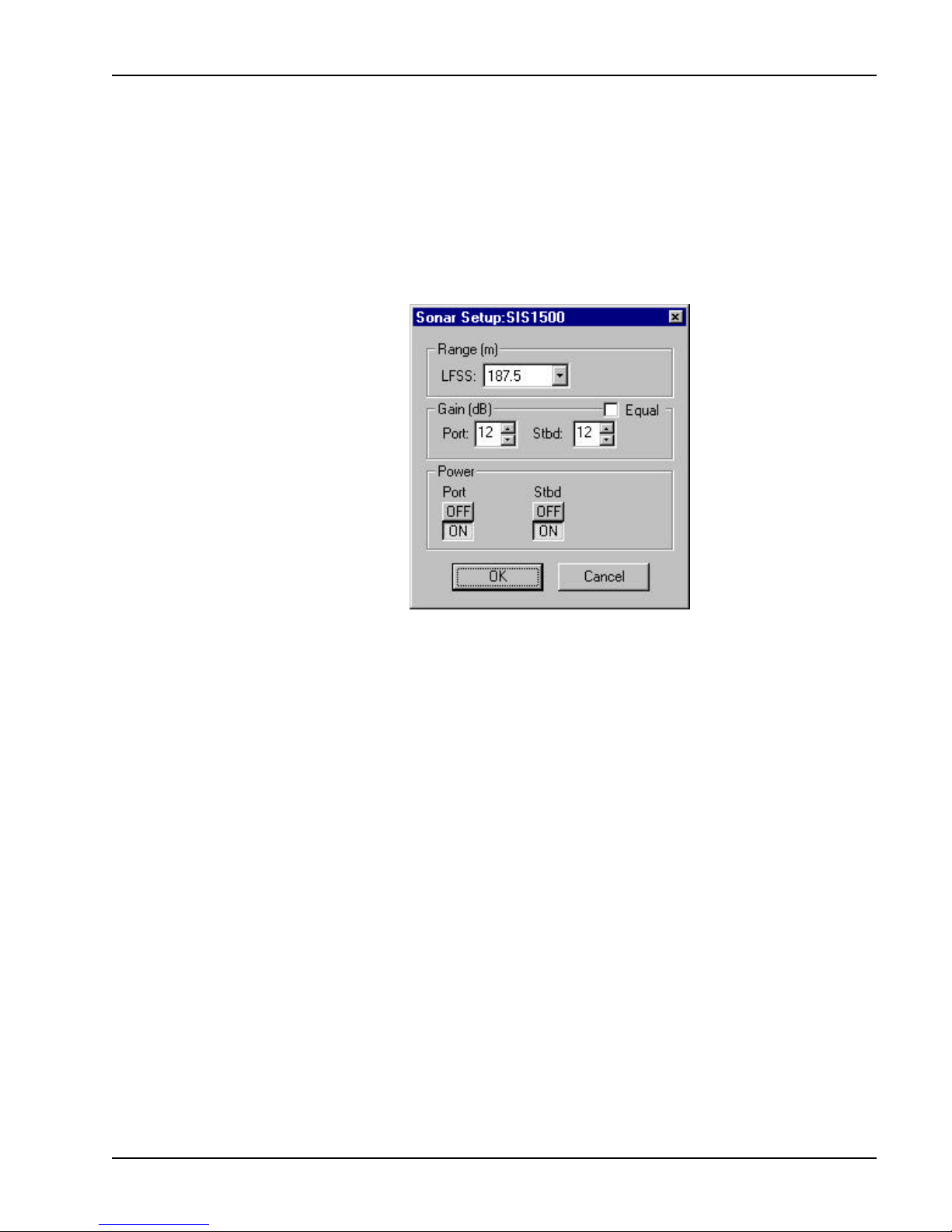
2. Click Configure Sonar in the System area of the Setup dialog box. The
Sonar Setup dialog box shown in Figure 3-10 opens.
Figure 3-10 The Sonar Setup Dialog Box
3. In the Range (m) area of the Sonar Setup dialog box click the down
arrow in the LFSS drop-down list box. A list of available sonar ranges
opens.
4. Select 187.5 from the LFSS drop-down list box.
5. In the Gain (dB) area of the Sonar Setup dialog box click the up or down
arrow in the Port scroll box to adjust the port channel receiver gain to 12,
and the up or down arrow in the Stbd scroll box to adjust the starboard
channel receiver gain to 12.
6. In the Power area of the Sonar Setup dialog box set the Port ON/OFF
switch to ON to power the port channel, and the Stbd ON/OFF switch to
ON to power the starboard channel.
7. Click OK to close the Sonar Setup dialog box and save the settings.
8. In the Setup dialog box click OK to close the Setup dialog box and save
the settings as the default settings, or click Cancel to close the dialog box
without saving the settings as the default settings.
SECTION 3 Setup and Deployment System Startup
Page 58
3-22 DATASONICS
Configuring the Display Parameter Settings
The display parameter settings should be verified or reconfigured in
accordance with the standard and optional sensors installed; however, they
can be changed at any time. When running Chirpscan3 for the first time, the
display parameter settings are set to display sidescan sonar data and data
from all the standard sensors. The displays include Port Sidescan and
Starboard Sidescan, Pitch and Roll, Heading and Course, and Altitude.
To verify or reconfigure the display setup parameters for all the standard
sensors:
1. Select File from the menu bar, and then choose Setup. The Setup dialog
box shown in Figure 3-8 on page 3-19 opens.
2. Click the SS, Bottom Track, PR, and HC data windows to turn them on.
3. In the Setup dialog box Click OK to close the Setup dialog box and save
the settings as the default settings, or click Cancel to close the dialog box
without saving the settings as the default settings.
4. Select Data Window from the menu bar, and then choose Attitude. The
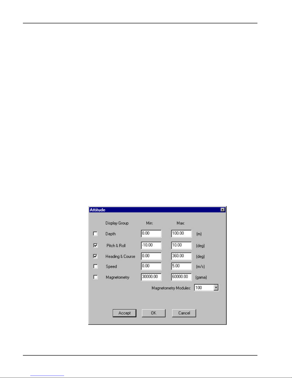
Attitude dialog box shown in Figure 3-11 opens.
5. Select the Pitch & Roll and Heading & Compass check boxes.
Figure 3-11 The Attitude Dialog Box
Volume ISystem Manual June 1998
Page 59
SIS-1500 Seafloor Imaging System 3-23
6. Type -10.00 and 10.00 into the Pitch & Roll Min and Max text boxes,
respectively.
7. Type 0.00 and 360.00 into the Heading & Course Min and Max text
boxes, respectively.
8. Click OK to close the Attitude dialog box and save any changes, or click
Cancel to close the dialog box without saving any changes.
Saving Setup Configurations
Once the parameter settings have been configured, they can be saved to a
file. Hence if the settings are changed, they can be easily recalled by loading
the saved setup configuration.
To save a setup configuration:
1. Select File from the menu bar, and then choose Setup. The Setup dialog
box shown in Figure 3-8 on page 3-19 opens.
2. Configure the navigation, sonar, and display parameter settings as
instructed in Parameter Settings beginning on page 3-18, and then click
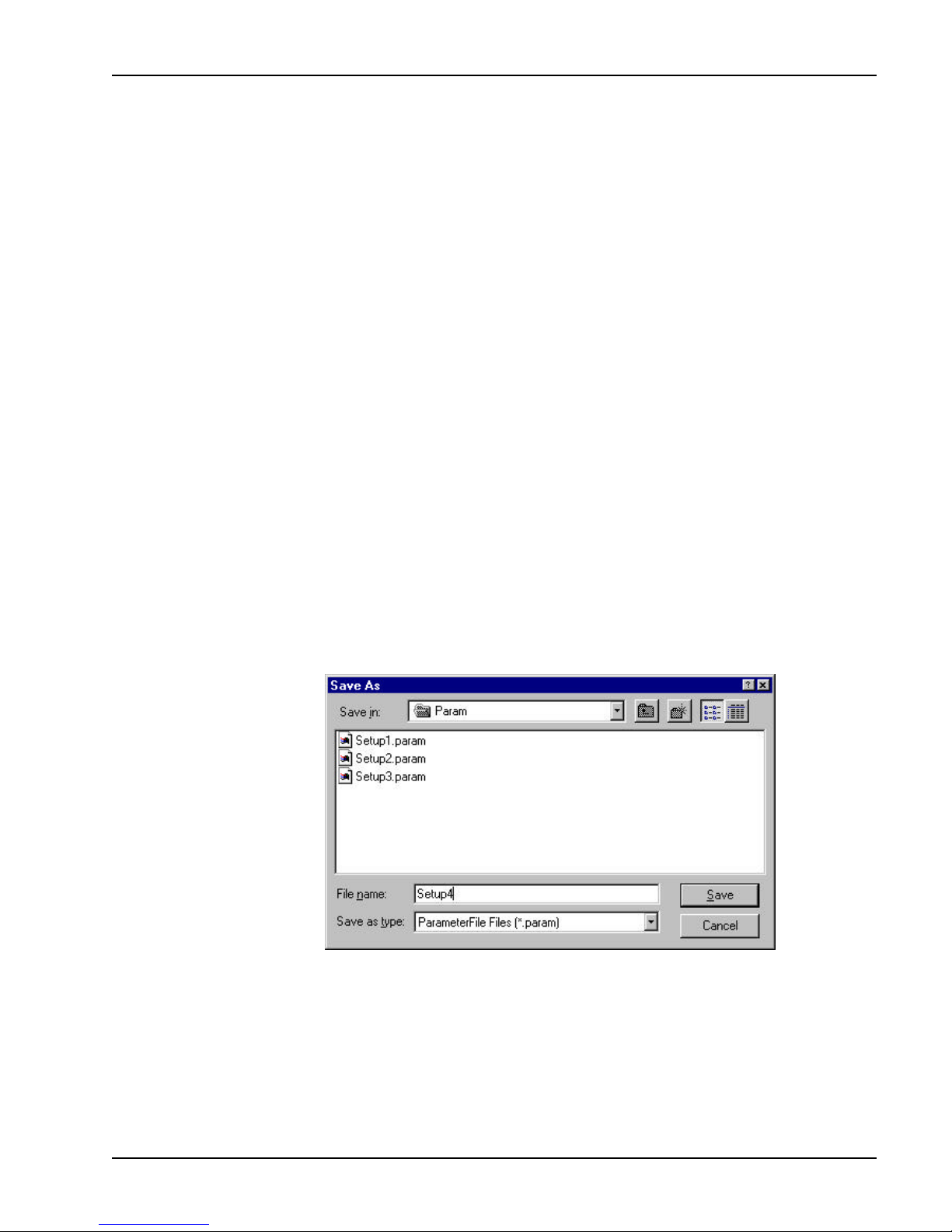
Save in the Setup dialog box. The Save As dialog box shown in
Figure 3-12 opens.
Figure 3-12 The Save As Dialog Box
3. Type the name of the file to save to in the File name text box and click
Save to save the file and close the Save As dialog box. It is not
necessary to type the file extension.
4. Repeat Steps 2 through 4 for as many setup configurations as desired.
SECTION 3 Setup and Deployment System Startup
Page 60
3-24 DATASONICS
Loading Setup Configurations
Once a setup configuration has been saved, it can be loaded. Once loaded,
it can be saved as the default setup.
To load a setup configuration:
1. Select File from the menu bar, and then choose Setup. The Setup dialog
box shown in Figure 3-8 on page 3-19 opens.
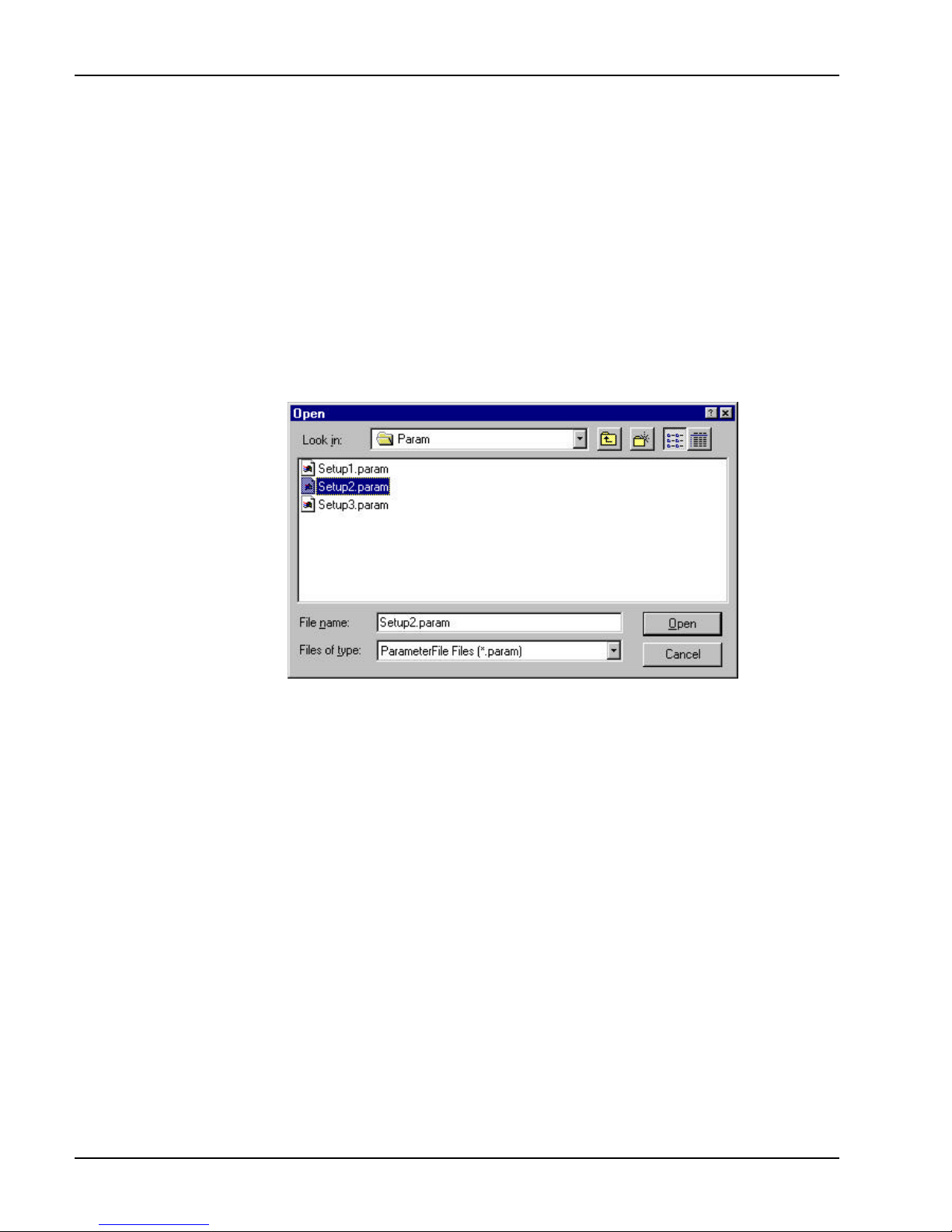
2. Click Load in the Setup dialog box. The Open dialog box shown in
Figure 3-13 opens.
Figure 3-13 The Open Dialog Box
3. Click a file name once to select it. When selected, the file name is
highlighted.
4. Double click the file name or click Open. The selected setup file is loaded
and the Open dialog box closes.
5. In the Setup dialog box click OK to close the Setup dialog box and save
the loaded settings as the default settings, or click Cancel to close the
dialog box without saving the loaded settings as the default settings.
Activating the Tow Vehicle
The tow vehicle must be activated before performing the predeployment
checks. Before activating the tow vehicle, check that it is properly connected
to the processor. With Chirpscan3 running and the Main window displayed,
perform the steps listed below to activate the tow vehicle.
Volume ISystem Manual June 1998
Page 61
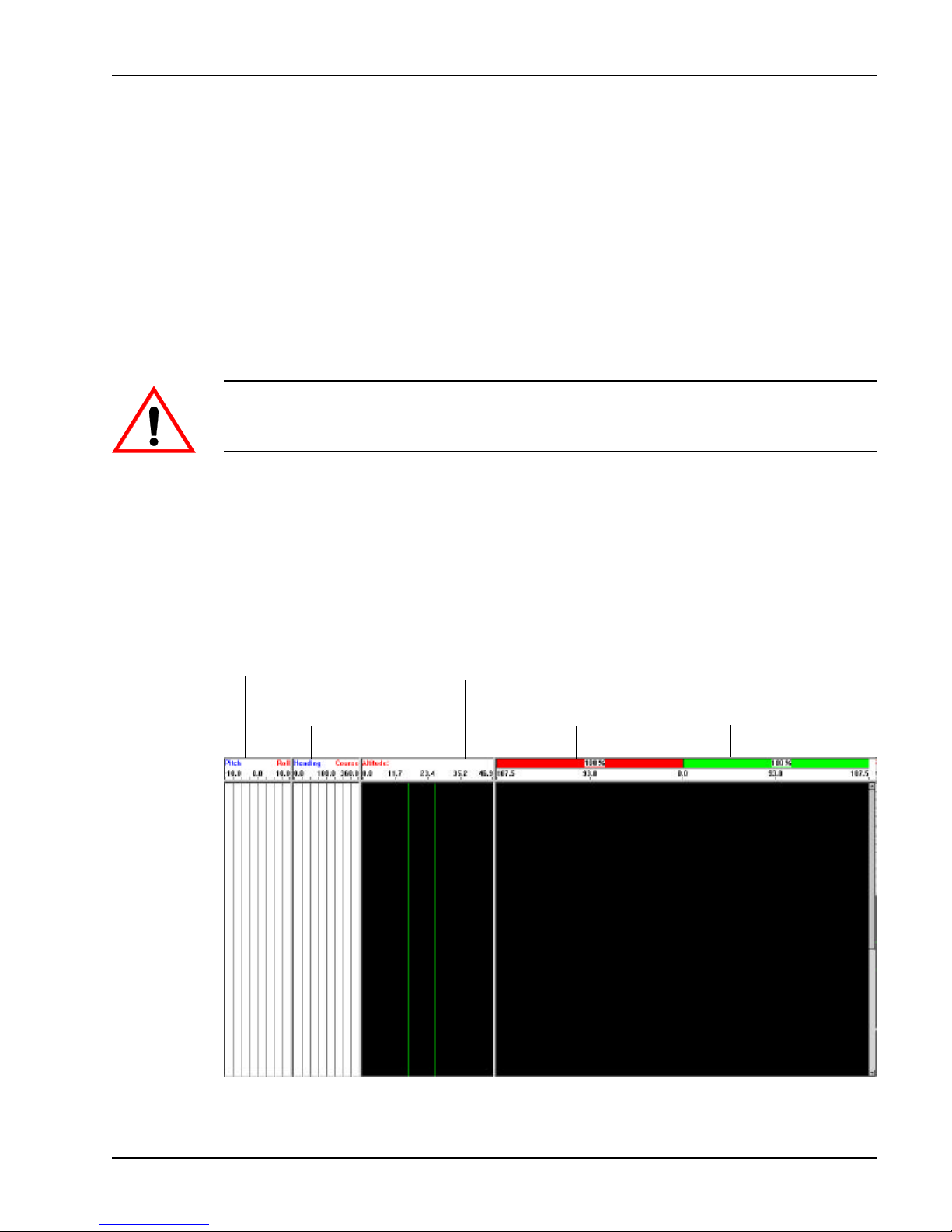
SIS-1500 Seafloor Imaging System 3-25
1. Turn on the Chirplink II Digital Multiplexer by switching the ON/OFF
switch to ON. The indicator in the switch will light.
2. Turn on the high voltage power supply by turning the HIGH VOLTAGE
key switch on the multiplexer to the right. The HIGH VOLTAGE indicator
will light and the XMIT LED indicator will flash, indicating that the tow
vehicle’s transducer arrays are transmitting. The indicator flashes once
for each transmission. The DATA LOCK LED will flash for a few seconds
and then illuminate continuously, and the TELEM LOCK LED will flash
for about 30 seconds and then illuminate continuously.
WARNING Do not allow the tow vehicle to transmit continuously on deck
for more than one half hour.
3. Select File from the menu bar, and then choose Start System. The
SIP-150 Sonar Image Processor begins acquiring data, and in the
Display area of the Main window the tow vehicle Pitch and Roll, Heading
and Course, and Altitude displays, and the Port Sidescan and Starboard
Sidescan displays shown in Figure 3-14 open.
Tow Vehicle Pitch
and Roll display
Tow Vehicle Heading
and Course display
Tow Vehicle
Altitude display
Port Sidescan
Sonar display
Starboard Sidescan
Sonar display
Figure 3-14 Pitch/Roll, Heading/Course, Altitude, and Sonar Displays
SECTION 3 Setup and Deployment System Startup
Page 62
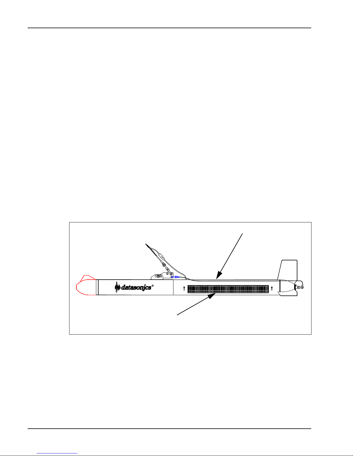
3-26 DATASONICS
Predeployment Checks
The predeployment checks are recommended in order to verify that the
system is functioning properly on deck before the tow vehicle is deployed.
The checks are easy to perform and consist of three procedures: rubbing the
transducer arrays to induce an acoustic signal which can be received and
displayed while allowing the transmitted pulse to be felt with the hand;
activating the Chirp pattern diagnostics to check the sonar receivers; and
verifying the receipt of the navigation and sensor data and the operation of
the sensors.
Rub Test
With the tow vehicle activated, perform the steps listed below to check the
sonar transmitters and receivers using the rub test technique.
1. With one hand rub the port transducer array back and forth ten or fifteen
times. It should be possible to feel the transmitted pulses. Refer to
Figure 3-15 for the location of the transducer arrays.
STARBOARD
TRANSDUCER
ARRAY
(OPPOSITE SIDE)
PORT TRANSDUCER
ARRAY
Figure 3-15 Location of the Port and Starboard Transducer Arrays
2. Examine the Port Sidescan Sonar display in the Main window. The
display should look similar to the one shown in Figure 3-16 with
horizontal streaks shown running across the display.
3. Rub the starboard transducer array ten or fifteen times and feel for the
transmitted pulses.
Volume ISystem Manual June 1998
Page 63
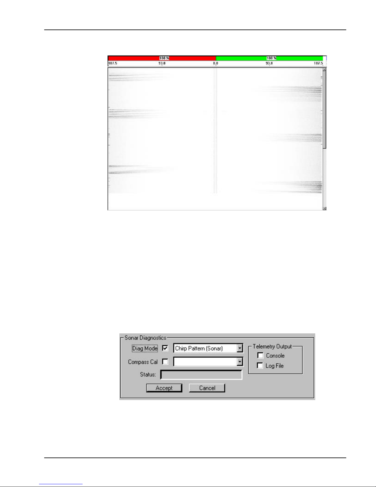
SIS-1500 Seafloor Imaging System 3-27
Figure 3-16 Rub Test Display
4. Examine the Starboard Sidescan Sonar display. The display should look
similar to the one shown in Figure 3-16.
Chirp Pattern Diagnostics Test
With the tow vehicle activated, perform the steps listed below to check the
sonar receivers using the Chirp pattern diagnostics.
1. Click Diagnostics in the Sonar Controls box in the Main window. The
Sonar Diagnostics box shown in Figure 3-17 opens.
Figure 3-17 The Sonar Diagnostics Box
SECTION 3 Setup and Deployment Predeployment Checks
Page 64
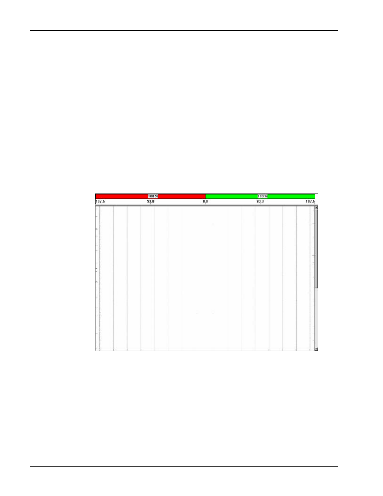
3-28 DATASONICS
2. Select the Diag Mode check box. The label “Diag Mode” turns red,
signifying that the command to go into diagnostic mode is ready to be
sent to the tow vehicle.
3. Click the down arrow in the Diag Mode drop-down list box. A list of
available diagnostics open.
4. Select Chirp Pattern (Sonar) from the Diag Mode drop-down list box.
5. Click Accept. The label “Diag Mode” turns black, signifying that the
command to go into diagnostic mode and start the chirp pattern
diagnostics has been sent to the tow vehicle, and the diagnostics start.
6. Examine the Port and Starboard Sidescan Sonar displays in the Main
window. They should look similar to those shown in Figure 3-18 with
black and gray bars running vertically in the display.
Figure 3-18 Chirp Pattern Test Display
7. Clear the Diag Mode check box. The label “Diag Mode” turns red,
signifying that the command to go out of diagnostics mode and stop the
chirp pattern diagnostics is ready to be sent to the tow vehicle.
8. Click Accept. The label “Diag Mode” turns black, signifying that the
command to stop the chirp pattern diagnostics has been sent to the tow
vehicle, and the diagnostics stop.
9. Click Cancel to close the Sonar Diagnostics box.
Volume ISystem Manual June 1998
Page 65
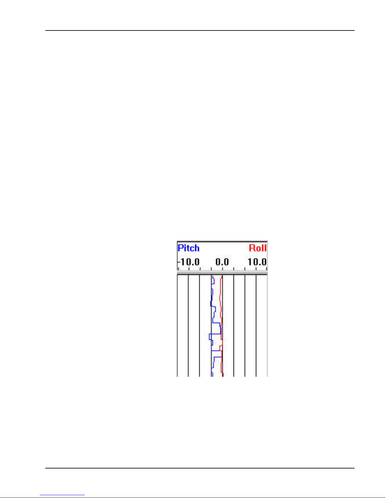
SIS-1500 Seafloor Imaging System 3-29
Data Telemetry and Sensor Tests
With the tow vehicle activated, perform the steps listed below to verify the
receipt of the navigation and sensor data, and to verify the correct operation
of the pitch, roll, and heading sensors.
1. Click Diagnostics in the Sonar Controls box in the Main window. The
Sonar Diagnostics box shown in Figure 3-17 opens.
2. Select the Console check box in the Telemetry Output area of the Sonar
Diagnostics box.
3. Verify that there is pitch, roll, heading, and navigation data displayed in
the Status display.
4. While observing the pitch and roll indications in the tow vehicle Pitch and
Roll display, move the vehicle’s nose up and down several times. Then
rotate the tow vehicle slightly to starboard and to port several times.
Verify that the pitch and roll indications in the tow vehicle Pitch and Roll
display change accordingly. An example of pitch and roll data in the tow
vehicle Pitch and Roll display is shown in Figure 3-19.
Figure 3-19 Displayed Pitch and Roll Data
Moving the tow vehicle’s nose up produces a positive pitch with the pitch
indication sweeping to the right, and moving it down produces a negative
pitch with the pitch indication sweeping to the left. Similarly, rotating the tow
vehicle to starboard produces a positive roll, and rotating it to port produces
a negative roll. The roll indication sweeps right and left, respectively.
SECTION 3 Setup and Deployment Predeployment Checks
Page 66
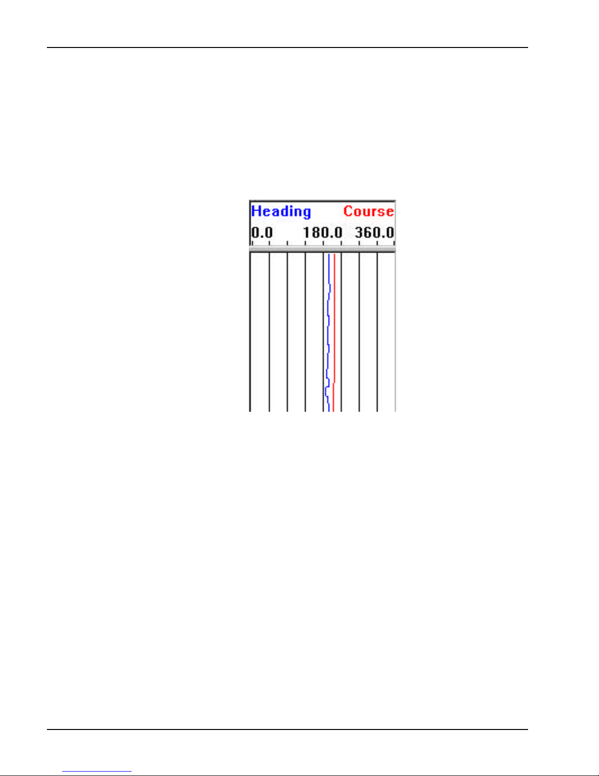
3-30 DATASONICS
5. While observing the heading indication in the tow vehicle Heading and
Course display, point the tow vehicle’s nose in different directions until
the indication in the display is approximately centered. Then swing the
nose to the right and to the left approximately 90 degrees each way.
Verify that the heading indication changes accordingly. An example of
heading data in the tow vehicle Heading and Course display is shown in
Figure 3-20.
Figure 3-20 Displayed Heading and Course Data
Moving the tow vehicle’s nose to the right causes the heading indication to
sweep to the right, and moving it to the left causes the heading indication to
sweep to the left.
6. Clear the Console Check box.
7. Click Cancel to close the Sonar Diagnostics box.
Launching the Tow Vehicle
When the predeployment tests are complete, the tow vehicle is ready to be
launched. The tow vehicle should be launched tail first from the stern of the
vessel using a boom or an A-frame and winch, or from the bow using a boom.
Perform the steps listed below to launch the tow vehicle and to verify its
stability and operation. If the high voltage power supply has been turned off,
turn it back on at this time by turning the HIGH VOLTAGE key switch on the
digital multiplexer to the right.
Volume ISystem Manual June 1998
Page 67
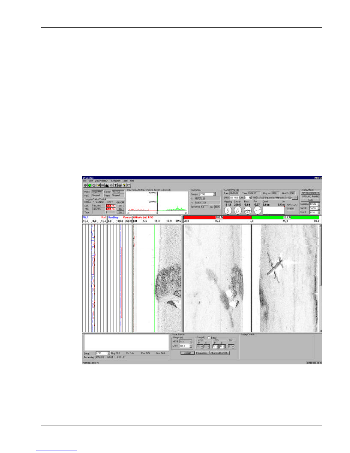
SIS-1500 Seafloor Imaging System 3-31
1. Lower the tow vehicle into the water tail first.
2. While cruising at 2 to 4 knots, submerge the tow vehicle to a depth of two
or three meters.
3. Click Start in the Parameters display in the Main window. The system will
begin acquiring data.
4. Check the attitude and stability of the tow vehicle. The pitch, roll, heading
and course indications should be stable. If not, the tow vehicle may be in
the ship’s prop wash and it may be necessary to lower the tow vehicle to
a deeper depth.
5. Examine the Port and Starboard Sonar displays in the Main window. If
the bottom is within range of the sonar, the port and starboard sidescan
sonar images will be displayed. An example is shown in Figure 3-21.
Figure 3-21 Example of SIS-1500 Sonar Images
SECTION 3 Setup and Deployment Launching the Tow Vehicle
Page 68

3-32 DATASONICS
Volume ISystem Manual June 1998
Page 69

SIS-1500 Seafloor Imaging System 4-1
SECTION 4
Theory of Operation
SECTION 4 Theory of Operation
Page 70

4-2 DATASONICS
Volume ISystem Manual June 1998
Page 71

SIS-1500 Seafloor Imaging System 4-3
n overall understanding of how the SIS-1500 Seafloor Imaging
System produces the high resolution sidescan sonar images is an
important factor in ensuring that the system is properly maintained
and its maximum performance realized. This section provides an overall
functional description of the system hardware components, signal flows and
processing, from the generation of the transmit signals to the acquisition and
processing of the received signals. Refer to Section 6, "Drawings," for the
wiring diagrams and assembly drawings called out in this section.
For descriptive purposes the system’s electronics hardware is divided into
two major functional components: the topside processor electronics and the
subsea electronics. They are connected with a single coaxial cable. The
topside processor electronics is the electronics hardware component of the
SIP-150 Sonar Image Processor. The subsea electronics is the electronics
hardware component of the TTV-195 Tow Vehicle.
Topside Processor Electronics
A block diagram of the SIP-150 Sonar Image Processor, which comprises the
SIP-150 Sonar Image Processor Workstation and the Chirplink II Digital
Multiplexer, is shown in Figure 4-1. Also refer to the wiring diagram for the
digital multiplexer, which is shown Drawing B150-08365.
With the exception of the Synchronizer board in the workstation and the
Multiplexer board in the digital multiplexer, all the circuit boards are OEM
supplied. Refer to the appropriate reference material provided by the
manufacturer for these boards. Listed below are the assembly drawing
numbers for the Synchronizer and Multiplexer boards.
Circuit Board Assembly Drawing
Synchronizer: B150-08061
Multiplexer: B150-08305
SECTION 4 Theory of Operation Topside Processor Electronics
Page 72
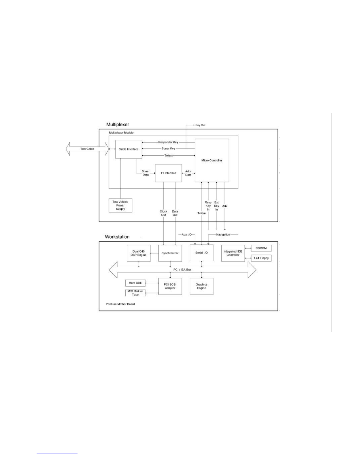
4-4 DATASONICS
Volume I System Manual June 1998
Figure 4-1 Topside Processor Electronics Block Diagram
Page 73

SIS-1500 Seafloor Imaging System 4-5
Workstation
Along with the high resolution monitor, the keyboard, and the pointing device,
the workstation comprises the following integrated components:
Host CPU. A Pentium based processor with serial communications
ports COM1 and COM2 and the parallel port LPT1.
SCSI interface. Connects to the internal hard drive and the optional
high density storage devices.
Serial I/O board. Provides two additional communications ports,
COM3 and COM4.
Graphics engine. Drives the high resolution monitor.
Synchronizer board. Inputs and formats the sonar data.
DSP engine. Processes the sonar data.
Integrated IDE controller. Interfaces with the 3.5" floppy drive.
1.44 Mbyte floppy disk drive. Provides an alternate medium for
system boot-up, the loading of programs, and the making of backup
copies.
The workstation interfaces with the digital multiplexer through its TELEM
serial port and its CLOCK IN and DATA IN connectors. The workstation’s
Pentium based host CPU runs the Chirpscan3 software and provides the
COM1 and COM2 serial communications ports and the LPT1 parallel port.
The COM1 port, which is the TELEM serial port, outputs the downlink
commands and inputs the uplink vehicle status information and sensor data.
The COM2 port connects to the pointing device on the keyboard, and the
LPT1 port connects to an optional printer. The Synchronizer board inputs the
sonar data and the clock signals from the DATA OUT and CLOCK OUT
connectors, respectively, on the multiplexer. Using the clock signals, the
Synchronizer board extracts the sonar data and formats the data into discrete
packets for output to the DSP engine. The DSP engine is a dual TMS320C40,
60 MHz digital signal processor (DSP), which performs the match-filter
processing of the sonar data. The Graphics engine drives the high resolution
1280 x 1024 color monitor. The SCSI interface services up to seven internal
or external devices, including the installed hard drive and the optional
magneto-optical drive. The Serial I/O board provides the COM3 and COM4
serial communications ports, where COM3 receives the navigation input and
COM4, which is the AUX I/O serial port, is a spare serial port.
SECTION 4 Theory of Operation Topside Processor Electronics
Page 74

4-6 DATASONICS
Digital Multiplexer
The main components of the digital multiplexer are the combination +5 VDC
and +/- 12 VDC power supply, which powers the multiplexer’s electronics; the
high voltage power supply, which powers the subsea electronics; and the
Multiplexer board, which performs all of the communications functions.
Specifically, the Multiplexer board includes the following functions:
Cable Interface. Combines the high voltage power with the downlink
commands and the sonar and transponder keys and transmits the
combination to the subsea electronics while it simultaneously receives
the sonar data, the tow vehicle status information, and the sensor data
from the subsea electronics.
T1 Receiver. Recovers the sonar data.
Modem. Modulates the downlink commands and demodulates the
uplink vehicle status information and sensor data.
Microcontroller board. Plugs into the Multiplexer board and
generates the sonar and responder keys and provides the downlink
and uplink data telemetry control.
An outline drawing of the digital multiplexer chassis is shown in Figure 4-2.
The digital multiplexer, in addition to functioning as the communications link
between the workstation and the subsea electronics, is also the subsea
electronics power supply. When the front panel circuit breaker CB1 is closed,
100 -125 VAC or 220 - 240 VAC, 50 - 60 Hz power is applied to the
multiplexer’s +/-12 VDC and +5 VDC power supply, which outputs +/- 12 VDC
and +5 VDC to the Multiplexer board. An indicator in the circuit breaker lights.
When the keyswitch S1 is closed, and if the circuit breaker has been closed,
+5 VDC is applied to the solid state relay K1. This closes the relay and applies
100 -125 VAC or 220 - 240 VAC, 50 - 60 Hz power to the three DC power
supplies. The three DC power supplies are wired in series to provide the high
voltage power, which is input to the Multiplexer board and output to the tow
vehicle. All the power supplies are auto sensing and automatically determine
whether the applied power is 100 - 125 VAC or 220 - 240 VAC, 50 to 60 Hz.
The applied power is also filtered with the AC line filter FL1. In addition, when
the keyswitch is closed, the yellow lamp LP1 on the front panel lights, the
front panel voltmeter indicates the voltage being output to the tow vehicle,
and the front panel ammeter indicates the current being output to the tow
vehicle. The front panel of the digital multiplexer also includes three LEDs:
D1, which is XMIT KEY and flashes once every time a sonar key is output to
Volume ISystem Manual June 1998
Page 75
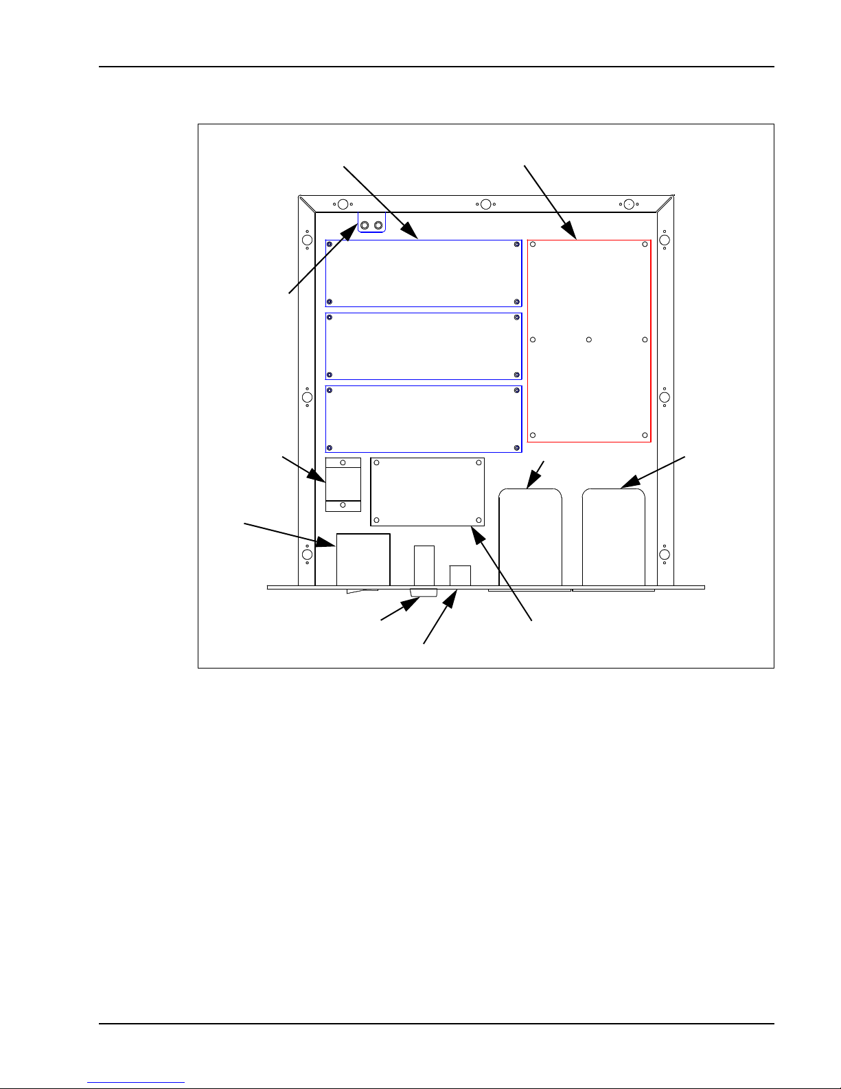
SIS-1500 Seafloor Imaging System 4-7
DC POWER
SUPPLY (3)
FILTER FL1
RELAY K1
CIRCUIT
BREAKER
CB1
MULTIPLEXER
BOARD
VOLTMETER
AMMETER
LAMP LP1
KEY SWITCH S1
+/-12 VDC & +5 VCD
POWER SUPPLY
Figure 4-2 Chirplink II Digital Multiplexer Chassis
the tow vehicle; D2, which is TELEM LOCK and flashes when the uplink and
downlink FSK telemetry is being established just after turning on the high
voltage power and is extinguished when the link is established; and D3, which
is DATA LOCK and flashes when the uplink T1 telemetry is being established
and is illuminated continuously when the link is established.
The Cable Interface on the Multiplexer board combines the high voltage
power with the downlink commands and the sonar and responder keys. The
downlink commands are input to the Microcontroller board on the Multiplexer
board from the workstation’s TELEM serial port in RS-232 format. The
Microcontroller board outputs the data to the Modem, which converts the data
into an FSK format that is centered at 35 kHz. The data are transmitted at
SECTION 4 Theory of Operation Topside Processor Electronics
Page 76

4-8 DATASONICS
9600 baud with the high voltage power along the coaxial cable to the subsea
electronics. The sonar key, which is first modulated by a 12.0625 kHz carrier
frequency, is also transmitted to the subsea electronics. And if a responder is
installed, a responder key, which is modulated by a 48.250 kHz carrier
frequency, is transmitted to the subsea electronics. The responder key is
either input to the multiplexer from an external source such as a navigation
or positioning system or generated by the Microcontroller board. The Cable
Interface also combines the uplink sonar data, the tow vehicle status
information, and the sensor data that are transmitted along the coaxial cable
from the subsea electronics. The uplink sonar data are transmitted at
1.544 Mbits/sec at frequencies of 90 kHz and higher using industry-standard
T1 telecommunications technology. This technology allows the sonar data to
be embedded with the synchronization and timing information for reliable
recovery by the T1 Receiver, which outputs the sonar data and clock signals
to the workstation as DATA OUT and CLOCK OUT, respectively. The uplink
vehicle status information and sensor data are transmitted at 9600 baud
using an FSK format, where the data are centered at 65 kHz. The data are
converted into RS-232 format by the Modem and output to the Microcontroller
board, which outputs the data to the TELEM serial port of the workstation.
Subsea Electronics
A block diagram of the subsea electronics is shown in Figure 4-3. Also refer
to the wiring diagram for the sonar electronics, which is shown Drawing
D150-08391.
The main components of the subsea electronics include the sonar
electronics, the port and starboard transducer arrays, and the standard and
optional sensors. The sonar electronics generates the Chirp waveforms,
transmits and receives the sonar signals, interfaces with the standard and
optional sensors, and communicates with the topside processor. The
transducer arrays transmit and receive the acoustic signals. The standard
sensors are the pitch, roll and heading sensors, and the optional sensors
include a temperature sensor, a pressure sensor, a cesium magnetometer,
and a responder, which is used to acquire tow vehicle positioning information.
All the circuit boards in the subsea electronics are contained in the sonar
electronics. There are eleven circuit boards in all, and their assembly drawing
numbers are listed below.
Volume ISystem Manual June 1998
Page 77
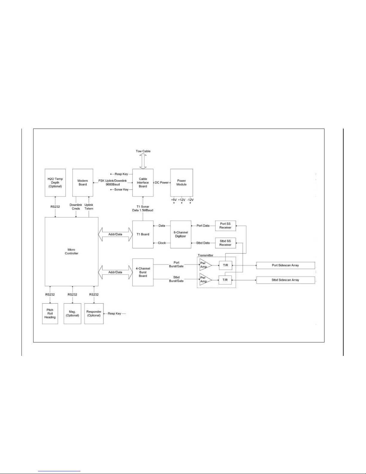
SIS-1500 Seafloor Imaging System 4-9
SECTION 4 Theory of Operation Subsea Electronics
Figure 4-3 Subsea Electronics Block Diagram
Page 78

4-10 DATASONICS
Circuit Board Assembly Drawing
Backplane: B150-08060
Cable Interface: B150-08301
Power: A150-08277
Modem: B150-08325
Microcontroller: B150-07926
Burst: B150-08307
Transmitter: B150-07894
Receiver: B150-07887
Digitizer: B150-08203
T1 Interface: B150-08298
Option: Custom designed per user specification
Sonar Electronics
An outline drawing of the sonar electronics chassis is shown in Figure 4-4.
The sonar electronics consists of a Melcher DC power supply, which
regulates the high voltage power from the topside processor to 48 VDC; an
energy storage capacitor bank, which provides stored energy; and the set of
eleven circuit boards, which perform the following functions:
Backplane board. Provides all of the interconnections between the
boards in the sonar electronics.
Cable Interface board. Combines the sonar data, the tow vehicle
status information, and the sensor data and transmits all this data to
the topside processor’s digital multiplexer while it simultaneously
receives the high voltage power, the downlink commands, and the
sonar and responder keys from the multiplexer.
Power board. Generates all the required low level DC voltages.
Modem board. Demodulates the downlink commands.
Microcontroller board. Controls all the functions of the tow vehicle.
Burst board. Generates the Chirp transmit waveforms.
Volume ISystem Manual June 1998
Page 79
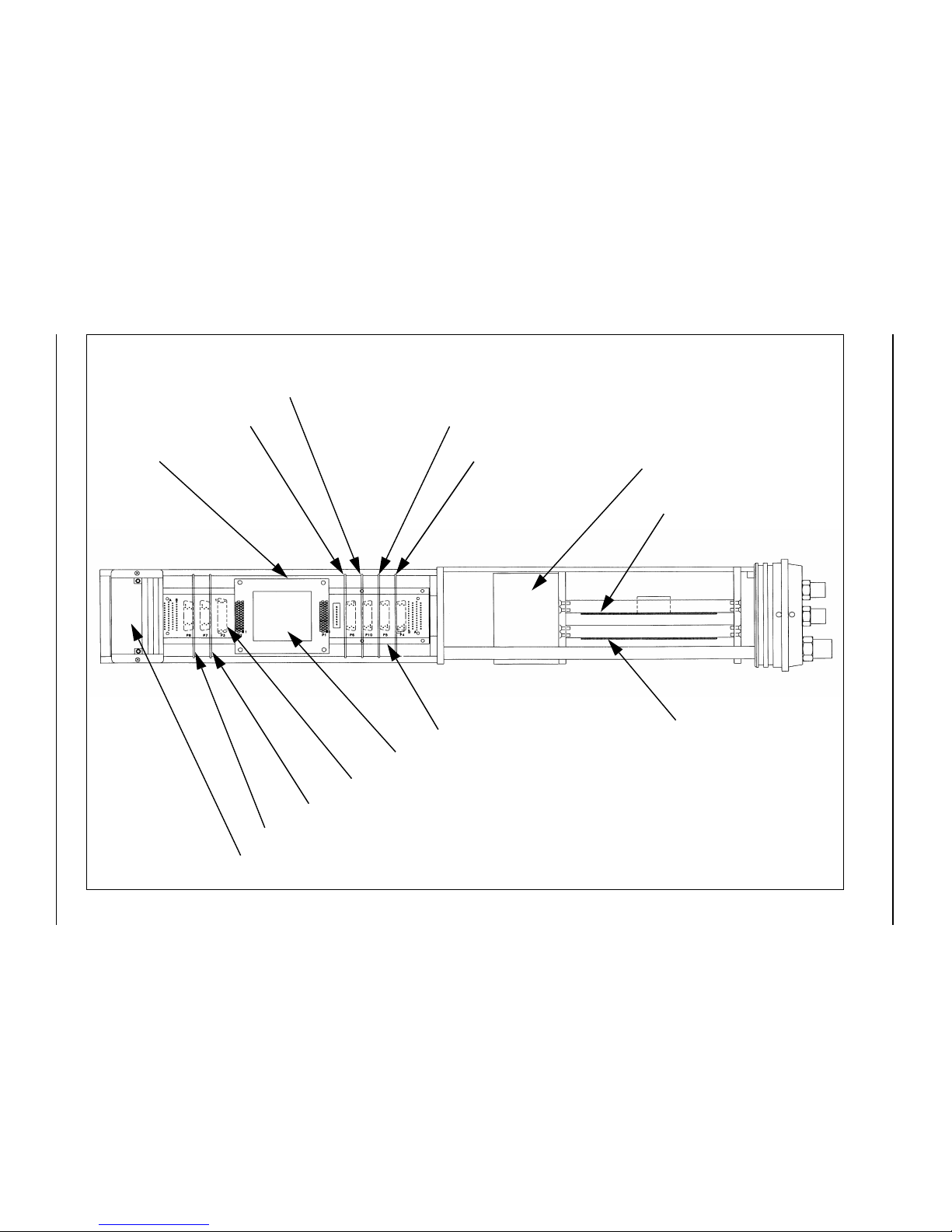
SIS-1500 Seafloor Imaging System 4-11
SECTION 4 Theory of Operation Subsea Electronics
Figure 4-4 Sonar Electronics Chassis
TRANSMITTER BOARD
RECEIVER BOARD
DIGITIZER BOARD
T1 INTERFACE BOARD
MODEM BOARD
BURST BOARD
OPTION BOARD CONNECTOR
PITCH/ROLL/HEADING SENSOR
POWER BOARD
CABLE INTERFACE BOARD
MICROCONTROLLER
BOARD
ENERGY STORAGE
CAPACITOR BANK
BACKPLANE BOARD
MELCHER DC POWER SUPPLY
Page 80

4-12 DATASONICS
Transmitter board. Transmits the sonar signals.
Receiver board. Receives the sonar signals.
Digitizer board. Converts the received sonar analog signals into a
serial data format.
T1 Interface board. Generates the sonar data telemetry.
Option board. A custom designed board for use with the optional
sensors.
All the boards except the Transmitter and Receiver boards plug directly into
the Backplane board. The Transmitter and Receiver boards connect to the
Backplane board through a wire harness.
The Cable Interface board in the sonar electronics connects directly to the
topside processor’s digital multiplexer through the coaxial cable. The inputs
to the Cable Interface board from the topside processor’s digital multiplexer
are the high voltage power, the downlink commands, the sonar key, and the
responder key; the outputs from the Cable Interface board to the topside
processor’s digital multiplexer are the uplink sonar data, the tow vehicle
status information, and the sensor data. The Cable Interface board filters the
high voltage power from the other signals. In addition, the Cable Interface
board demodulates the sonar and responder keys and converts them into
digital pulses. These pulses key the sonar electronics and the responder,
respectively.
The Power board inputs DC power from the Cable Interface board and
generates regulated +/-12 VDC and +5 VDC power for the sonar electronics
and the standard and optional sensors.
The Modem board inputs the FSK downlink command signals from the Cable
Interface board, demodulates the signals, and converts them into an RS-232
format, which is then output to the Microcontroller board. In addition, the tow
vehicle status and sensor data are output from the Microcontroller board in
RS-232 format to the Modem board, which converts the data into FSK signals
that are output to the Cable Interface board.
The Microcontroller board interfaces with most of the other circuit boards in
the sonar electronics. It provides the Chirp pulse width control, the timing
information and the sonar key to the Burst board; controls the fixed gain, the
time varying gain (TVG), and the diagnostics on the Receiver boards; and
interfaces with the T1 Interface board. The Microcontroller board also
Volume ISystem Manual June 1998
Page 81

SIS-1500 Seafloor Imaging System 4-13
connects to the pitch, roll, and heading sensors through an RS-232 serial
port, and to the optional cesium magnetometer, pressure sensor, and
responder through three additional RS-232 serial ports. The Microcontroller
board, upon power up, initializes the sonar electronics and invokes a ping
cycle four times a second, which is the default repetition rate. The repetition
rate, along with the Chirp pulse widths, transmitter on and off, receiver gain,
and diagnostics, is controlled with the downlink commands from the topside
processor.
The Burst board generates the Chirp transmit waveforms and the transmit
gate for each channel. The sonar transmit signal frequencies sweep in the
190 kHz to 210 kHz band with the port and starboard sonars sweeping in
opposite directions. This technique minimizes crosstalk between the two
channels. The transmit gates, which control the pulse width of the transmitted
signals, are output to the Transmitter boards and are automatically set in
accordance with the range setting. The range is operator settable and is
controlled by the Microcontroller board in accordance with the corresponding
downlink commands. The transmit waveforms are also output to the Receiver
board and function as the diagnostic signals to assist in fault isolation.
The Transmitter board is a dual channel transmitter that amplifies the transmit
signals that are input from the Burst board and drives the corresponding port
and starboard transducer arrays through two independent impedance
matching transformers and transmit/receive (T/R) networks. The T/R
networks allow the transducer arrays to both transmit and receive acoustic
signals, where otherwise separate transmit and receive transducer arrays
would be required for each channel.
The Receiver board amplifies and filters the signals received by the port and
starboard transducer arrays, and it inputs the port and starboard diagnostic
signals from the Burst board. Both fixed gain and time varying gain are
applied. The level of the fixed gain is operator adjustable and is controlled by
the Microcontroller board in accordance with the corresponding downlink
command. The time varying gain, which is not operator adjustable,
compresses the dynamic range of the received signals, which can be as high
as 120 dB, to that which can be processed with 16 bits, or about 96 dB. This
is done by increasing the receiver gain with time over that of the fixed gain at
a rate that compensates for losses in the transmitted signals due to the
effects of spreading loss and grazing angle. Although the rate at which the
time varying gain increases is fixed, the length of time it is applied varies with
the repetition rate, decreasing proportionately with increasing repetition rate.
The gain increases from -20 dB at the beginning of a ping cycle to a maximum
SECTION 4 Theory of Operation Subsea Electronics
Page 82

4-14 DATASONICS
of 40 dB. Once amplified, the received signals are mixed with a local oscillator
frequency and the difference frequency, or base band, which is the swept
frequency bandwidth, is output to the Digitizer board.
The Digitizer board is a six channel, 16-bit analog to digital converter that
inputs the amplified and filtered signals from the Receiver board. The four
additional channels can be used to input analog signals from the optional
sensors. The input signals from all six channels are sampled simultaneously
at 48 kHz and output to the T1 Interface board in an interleaved serial output
format.
The T1 Interface board, which inputs the serial data outputs from the Digitizer
board, is used to format the serial data in accordance with the T1
specification. The formatted data is output at 1.544 Mbits/sec to the Cable
Interface board. The T1 Interface board also generates the clock signals
required by the Digitizer board.
Transducer Arrays
There are two independent transducer arrays: one on the port side and one
on the starboard side of the TTV-195 Tow Vehicle. They are both
independently connected to the Transmitter board in the sonar electronics.
Each transducer array consists of six precisely spaced transducer elements
that are positioned in a straight line to form a linear array with specific beam
characteristics: a narrow horizontal beam, which contributes to the high
resolution imaging in the along-track dimension, and a wide vertical beam,
which provides wide bottom coverage in the cross-track direction. In addition,
the down-look angle of each transducer array is adjustable from 0° to 20° in
10° increments.
Standard and Optional Sensors
The standard sensors are the pitch, roll, and heading sensors, and the
optional sensors include a temperature sensor, a pressure sensor, and a
cesium magnetometer. All the sensors are installed within the tow vehicle or
mount externally to the tow vehicle, and they connect to the sonar electronics
either with an RS-232 interface or with a direct analog connection. In addition,
an optional responder, which is triggered by the responder key, can be
installed in the tow vehicle. The responder is used with an acoustic tracking
system to provide tow vehicle positioning. Both the responder’s transducer
and the temperature sensor are contained within the nose of the tow vehicle,
and the pressure sensor is contained within the nose end cap.
Volume ISystem Manual June 1998
Page 83

SIS-1500 Seafloor Imaging System 5-1
SECTION 5
Maintenance and
Troubleshooting
SECTION 5 Maintenance and Troubleshooting
Page 84

5-2 DATASONICS
Volume ISystem Manual June 1998
Page 85

SIS-1500 Seafloor Imaging System 5-3
T
he routine maintenance of the SIS-1500 Seafloor Imaging System
primarily involves the periodic inspection of the SIP-150 Sonar Image
Processor air filters, the backing up of the processor’s internal hard
drive, and the washing and inspection of the TTV-195 tow vehicle. This
section encompasses the maintenance procedures that will help ensure
continued, reliable performance from the system, and troubleshooting guides
that will assist in isolating and correcting any problems that may be
encountered during setup and deployment. Also, a list of recommended test
equipment, tables of downlink commands and uplink data, and check and
calibration procedures are provided. This information can be used for
troubleshooting any performance problems or hardware failures.
Processor Periodic Maintenance
The SIP-150 Sonar Image Processor is built from highly reliable components
and requires a minimum of maintenance; however, to maintain the best
performance and to avoid premature hardware failures, periodic
maintenance should be performed. This includes cleaning the air filters,
making backups, and using hard disk maintenance utilities.
NOTE Keeping the air filters clean is important. Dirty air filters will restrict
the flow of cooling air to the hardware components which can cause heat
damage and failure.
Air Filter Cleaning
The topside processor’s workstation has three air filters: two are located on
the back panel and the third is located behind the vent plate on the front
panel. To remove the filters on the back panel of the workstation, first snap
the filter covers off, and then remove the filters and clean or replace them. To
remove the filter on the front panel of the workstation, first unscrew the vent
plate, and then remove and clean or replace the filter.
Backups
It is recommended that the workstation’s internal hard drive be backed up on
a regular basis. This will ensure, should the hard drive fail, that it can be
restored to its original configuration, hence eliminating time-consuming
SECTION 5 Maintenance and Troubleshooting Processor Periodic Maintenance
Page 86

5-4 DATASONICS
reloading of programs and loss of data. Backups should be done on high
density, removable hard disks or tapes, such as the Hewlett-Packard
magneto-optical disks or the Exabyte 8 mm cartridge tapes.
Hard Disk Maintenance Utilities
The regular use of hard disk maintenance utilities such as Microsoft ScanDisk
and Disk Defragmenter will greatly reduce the risk of hard drive failure, data
loss and degraded performance of the hard drive.
NOTE Use of an external degaussing device can permanently damage the
monitor. Use only the monitor’s own internal degaussing device.
Tow Vehicle Periodic Maintenance
Maintenance of the TTV-195 Tow Vehicle is required after each use and
includes washing and inspecting the tow vehicle and the cables and
connectors.
Cleaning and Inspection
After the tow vehicle is retrieved from service, perform the steps below to
clean and inspect the tow vehicle.
1. Wash down the tow vehicle, inside and out, with clean, fresh water and
remove any debris that may have become trapped.
2. Inspect the face of the transducer arrays. Spray them with fresh water,
and then clean them with a mild, non-abrasive detergent, being careful to
remove any buildup. After cleaning, spray them again with fresh water.
NOTE Do not use an ammonia-based cleaner such as a glass cleaner to
clean the transducer arrays.
3. Check for loose cable connections or other signs of damage. The
underwater connectors in the tow vehicle and on the tow cable or deck
cable should be kept clean. Clean the connector pins and sockets with
an alcohol wipe. Also, before reconnecting any of the cables, lubricate
the pins with an O-ring quality silicone or barium based lubricant.
Volume ISystem Manual June 1998
Page 87

SIS-1500 Seafloor Imaging System 5-5
NOTE Be especially careful not to get any lubricant on the faces of the
transducer arrays as this will severely degrade their performance.
4. Inspect the shear pin for damage. Replace the pin if it appears worn or
damaged.
5. Verify that the socket head retaining screws that secure the tail fins are
snug.
Tow Vehicle Disassembly and Reassembly
The tow vehicle consists of four main subassemblies: the nose, the
electronics housing, the tail assembly, and the sonar transducer housing.
These components are shown in Figure 5-1. To access the sonar electronics
in the electronics housing, the nose and the electronics housing must be
removed. To access the sonar transducers in the sonar transducer housing,
the tail assembly and the sonar transducer housing must be removed.
Electronics Housing Disassembly
To disassemble the electronics housing and access the sonar electronics:
1. Prepare a clean, dry work area.
2. Using the supplied 1/4” drive palm ratchet extension tool, loosen the
closure bolt located in the nose by turning it counterclockwise until the
nose detaches from the housing.
3. Carefully pull the nose a few inches from the housing, far enough to
access the in-line connector, which is included only if one or more of the
optional sensors are installed.
4. Disconnect the in-line connector, if included, and set the nose aside.
5. Disconnect the safety cable from the towing arm by removing the safety
cable shackle.
6. While grasping or securing the sonar transducer housing, pull the
electronics housing straight out until it is clear of the electronics chassis
and set it aside.
7. To remove any of the circuit boards, or to remove the energy storage
capacitor bank, first remove the corresponding hold-down bar.
SECTION 5 Maintenance and Troubleshooting Tow Vehicle Periodic Maintenance
Page 88
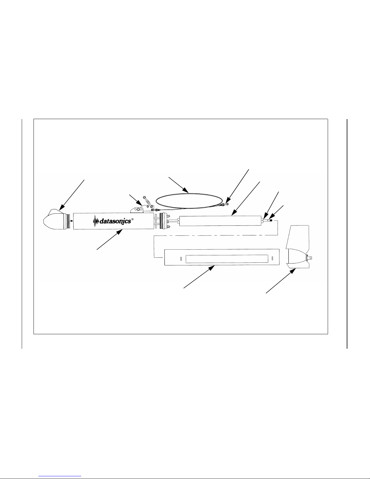
5-6 DATASONICS
Volume I System Manual June 1998
Figure 5-1 Tow Vehicle Disassembly
TAIL ASSEMBLY
NOSE
ELECTRONICS
HOUSING
SONAR TRANSDUCER
HOUSING
SAFETY CABLE
SONAR TRANSDUCERS
AFT RETAINING
RING LOCATION
SAFETY CABLE SHACKLE (2)
TRANSDUCER
MOUNTING ROD
TOWING ARM
Page 89

SIS-1500 Seafloor Imaging System 5-7
Electronics Housing Reassembly
To reassemble the electronics housing:
1. Inspect the O-rings on the nose and the end cap. They should be free of
any scratches, nicks or dirt. In addition, inspect the O-ring surfaces on
the electronics housing. They should also be free of any scratches, nicks
or dirt.
If necessary, wipe the O-rings clean with an alcohol wipe and apply a light
coat of silicone lubricant. Replace any O-ring that appears cracked or
nicked.
When replacing an O-ring, first clean the O-ring surface on the housing
with a clean, lint-free cloth or paper towel, and then apply a thin coat of
silicone lubricant to the new O-ring before installing it onto the nose or end
cap.
2. Slide the electronics housing over the electronics chassis and align the
slot on the housing with the tab in the end cap.
3. Press the housing onto the end cap until the tab in the end cap is fully
inserted into the slot in the housing.
4. Connect the in-line connector, if included, to the connector on the nose.
5. Align the guide pin on the nose with the hole in the electronics chassis
and insert the nose into the electronics housing, pressing it into the
housing until the rim of the housing is just past the first O-ring.
6. While pressing the nose against the housing, turn the closure bolt in the
nose clockwise until the nose is fully seated against the housing. Do not
overtighten.
7. Attach the safety cable shackle to the towing arm.
Sonar Transducer Housing Disassembly
To disassemble the sonar transducer housing and access the sonar
transducers:
1. Prepare a clean, dry work area.
2. Disconnect the safety cable from the towing arm and the tail assembly by
removing the shackles, and then remove the cable entirely.
3. Remove the four down-look angle adjusting screws. Refer to Figure 3-6
on page 3-16 for the location of the screws.
SECTION 5 Maintenance and Troubleshooting Tow Vehicle Periodic Maintenance
Page 90

5-8 DATASONICS
4. Using the supplied 1/4” drive palm ratchet extension tool, loosen the
closure bolt located in the tail assembly by turning it counterclockwise
until the tail assembly detaches from the sonar transducer housing.
5. Remove the tail assembly and set it aside.
6. While grasping or securing the electronics housing, pull the sonar
transducer housing straight out until it is clear of the end cap by a few
inches, far enough to access the connectors on the end cap.
7. Pull the tow vehicle cable pigtail through the access hole from inside the
housing and let the cable lie to the side.
8. Slide the housing the rest of the way out and set it aside.
9. To remove the transducers, remove the aft retaining ring, disconnect the
transducer cables from the end cap, and then slide the transducers off
the transducer mounting rod.
Sonar Transducer Housing Reassembly
To reassemble the sonar transducer housing:
1. If the transducers have been removed, reinstall them onto the transducer
mounting rod, making sure the cables are positioned on the same side as
the towing arm, and then reconnect the transducer cables and reinstall
the aft retaining ring.
2. Slide the housing over the transducers until the rim of the housing is a
few inches from the end cap, and then insert the tow vehicle cable pigtail
through the access hole in the housing.
3. Align the slot on the housing with the tab in the end cap and press the
housing onto the end cap until the tab in the end cap is fully inserted into
the slot in the housing.
4. Position the transducers such that all four down-look angle adjusting
screw holes are visible and install the down-look angle adjusting screws,
leaving them loose with the screw shoulders free of the housing.
5. Align the tab on the tail assembly with the slot on the housing and insert
the tail assembly into the housing.
6. While pressing the tail assembly against the housing, turn the closure
bolt in the tail assembly clockwise until the tail assembly is fully seated
against the housing. Do not overtighten.
7. Attach the safety cable shackles, reinstall the safety cable, and position
and tighten the four down-look angle adjusting screws.
Volume ISystem Manual June 1998
Page 91

SIS-1500 Seafloor Imaging System 5-9
System Troubleshooting
If during the system startup, the tow vehicle activation, the predeployment
checks, or the operation of the system, either the SIP-150 Sonar Image
Processor or the TTV-195 Tow Vehicle does not appear to be functioning
properly, refer to the troubleshooting guides in this section and to the
functional descriptions in Section 4, "Theory of Operation." The
troubleshooting guides will assist in quickly isolating the problem, and should
the problem be in the processor or subsea electronics, the theory of operation
will assist in tracing the source of the problem to the subassembly or
component.
NOTE If the problem appears to be in the software, refer to the Chirpscan3
manual.
Recommended Test Equipment
Below is a list of recommended test equipment for troubleshooting any
performance problems or hardware failures.
• Fluke 70 Series multimeter or equivalent
• Wavetek Model 29 10 MHz DDS function generator or equivalent
• Tektronics Model TAS 250 (analog) or Tektronics 2212 (analog &
digital) oscilloscope or equivalent
• Leader LDC-822 digital counter or equivalent
• Leader Model LMV-181A AC millivoltmeter or equivalent
• Topward Model TPS-4303 DC power supply or equivalent
• J.F.W. Model 50 DR-001 signal attenuator (50 ohm, 0-110 dB, 1 dB
steps) or equivalent
• TIF IT-990 500 V megometer or equivalent
• SIS-1500 Backplane board extender card, 30-pin
• SIS-1500 Backplane board extender card, 40-pin
• Tektronics TEK 1503C metallic time domain reflectometer
SECTION 5 Maintenance and Troubleshooting System Troubleshooting
Page 92

5-10 DATASONICS
Troubleshooting Guides
Troubleshooting guides for assisting in the isolation and correction of
problems that may occur before deploying the tow vehicle are presented in
Table 5-1, Table 5-2, and Table 5-3. The tables are sequenced in the order
of the processor startup procedures, the tow vehicle activation procedures,
and the predeployment checks procedures, as presented in Section 3, "Setup
and Deployment." In addition, Table 5-4 provides a guide for isolating and
correcting any problems that may occur after the tow vehicle is deployed. All
the tables present possible symptoms based on historical repair activities and
recommend the most likely corrective action.
WARNING Before disconnecting any cables or removing any boards from
the subsea electronics, be sure that the high voltage power supply is off. To
turn the high voltage power supply off, turn the HIGH VOLTAGE key switch
on the digital multiplexer to the left. The HIGH VOLTAGE indicator will turn
off. Also, before disconnecting any cables or removing any boards from the
topside processor, be sure the 100 - 125 VAC or 220- 240 VAC, 50 - 60 Hz
power source is disconnected.
When using the troubleshooting guides, perform the corrective actions for
any given symptom in the order presented until the problem is corrected or
isolated. When the corrective action calls for checking a board or checking
wiring or connectors, refer to Section 4, "Theory of Operation," for the board
location and general description, and to Section 6, "Drawings," for the
assembly drawings and the wiring diagrams. The troubleshooting guides also
call for three procedures that are included in this section: the cable checks for
checking transducer array cables and connectors, the transducer array
checks for checking the transducer arrays, and the heading sensor
calibration for calibrating the heading sensor. In addition, tables of downlink
commands and uplink vehicle status and sensor data are provided in this
section for evaluating the performance of the communications link.
Table 5-1 Processor Startup Problems
Symptom Possible Cause Corrective Action
The Main window does not
open when choosing the
Chirpscan3 icon. The error
message “Hardlock E-Y-E
not found.” is displayed.
The cable from the host CPU
parallel port is not properly
connected to the keylock or is
faulty.
Verify that the cable that
connects the host CPU to the
sentinel. The cable is located
inside the workstation.
Volume ISystem Manual June 1998
Page 93

SIS-1500 Seafloor Imaging System 5-11
Table 5-2 Tow Vehicle Activation Problems
Symptom Possible Cause Corrective Action
Both the VOLTS meter and
the AMPS meter on the
front panel of the digital
multiplexer show no
indication.
The VOLTS meter indicates
a voltage that is less than
140 volts, and/or the
AMPERES meter shows no
current fluctuations or a
current over 500 ma.
The digital multiplexer is not
powered.
The +/-12 VDC and +5 VDC
power supply in the digital
multiplexer is not functioning.
The three DC power supplies
that supply high voltage
power to the tow vehicle are
not powered.
One or more of the three DC
power supplies that supply
high voltage power to the tow
vehicle are not functioning
properly.
Verify that the ON/OFF and
HIGH VOLTAGE indicators
on the front panel of the
digital multiplexer are on. If
they are not on, check all the
VAC power connections.
Check the +/-12 VDC and
+5 VDC power supply.
Replace the power supply if it
has failed.
Check the solid state relay K1
in the digital multiplexer. The
relay should switch VAC
power to the three DC power
supplies when the HIGH
VOLTAGE switch is turned
on. If VAC power is not
present, check the line filter
FL1.
Turn off the high voltage
power supply and then
disconnect the deck cable or
the armored coaxial tow cable
from the digital multiplexer.
Turn the high voltage power
supply back on. If the voltage
and current readings still are
not correct, verify that the
VAC power is 100 - 125 VAC
or 220 - 240 VAC, 50 - 60 Hz.
If the VAC power is correct,
check each of the three DC
power supplies. Replace any
power supply that has failed.
SECTION 5 Maintenance and Troubleshooting System Troubleshooting
The deck cable or the
armored coaxial tow cable is
faulty.
Turn off the high voltage
power supply and reconnect
the deck cable or the armored
coaxial tow cable to the digital
multiplexer. While observing
the VOLTS meter and the
AMPERES meter, turn the
high voltage power supply
back on.
(Cont.)
Page 94

5-12 DATASONICS
Table 5-2 Tow Vehicle Activation Problems
Symptom Possible Cause Corrective Action
The VOLTS meter indicates
a voltage that is less than
140 volts, and/or the
AMPERES meter shows no
current fluctuations or a
current over 500 ma.
(Cont.)
The deck cable or the
armored coaxial tow cable is
faulty.
(Cont.)
The Power board in the sonar
electronics is not functioning
or one of the other circuit
boards is faulty.
The voltage should read
greater than 140 volts, and
the current should deflect to a
peak value for about
2 seconds, settle to about
300 ma, and then pulse at
four times a second. If the
proper readings are not
observed, refer to Cable
Checks on page 5-19 and
check the cable.
In the electronics housing, if
none of the LEDs on the
Backplane board are
illuminated, check the output
of the Melcher DC Regulator
for 48 VDC. If 48 VDC is not
present, check the input for
144 VDC. If 144 VDC is
present, replace the
regulator. If 144 VDC is not
present, replace the Cable
Interface board.
If one or more, but not all of
the LEDs on the Backplane
board are not illuminated,
remove all of the boards from
the Backplane board with the
exception of the Power board.
In addition, disconnect the
wire harness that connects
the Transmitter and Receiver
boards to the Backplane
board. If one or more of the
LEDs still are not illuminated,
replace the Power board.
If all the Backplane board
LEDs are illuminated when all
the boards are disconnected,
reinsert each board (and
reconnect the wire harness),
one at a time, while observing
the Backplane board LEDs. If
any of the LEDs extinguish,
replace the last board
inserted or connected.
Volume ISystem Manual June 1998
Page 95

SIS-1500 Seafloor Imaging System 5-13
Table 5-2 Tow Vehicle Activation Problems
Symptom Possible Cause Corrective Action
The VOLTS meter indicates
a voltage that is less than
140 volts, and/or the
AMPERES meter shows no
current fluctuations or a
current over 500 ma.
(Cont.)
The tow vehicle does not
respond to commands.
The Microcontroller board is
not functioning.
The serial port settings are
incorrect.
Verify that the red LED on the
Microcontroller board is
blinking. If it is not, replace
the board.
Click Start from the Windows
Taskbar, select Settings, and
then choose Control Panel.
Double click the System icon
in the Control Panel window,
and then select the Device
Manager tab in the System
Properties window.
Verify that the View devices
by type option button is
selected, and then double
click Ports.
One at a time, select the
communications ports, click
Properties, and then select
the Resources tab in the
Properties window. Verify the
following settings:
Serial Port Address IRQ
COM1 03F8 04
COM3 02F8 05
COM4 02E8 10
NOTE: COM2 is used for
the pointing device and is
not shown as available.
Use Windows HyperTerminal
from the Windows
Accessories program group
to send a command to the
tow vehicle. For example,
type TLF 1 <CR> to set the
repetition rate to the 25 meter
range. For other commands
refer to Downlink Commands
begining on page 5-21.
SECTION 5 Maintenance and Troubleshooting System Troubleshooting
Page 96

5-14 DATASONICS
Table 5-2 Tow Vehicle Activation Problems
Symptom Possible Cause Corrective Action
The tow vehicle does not
respond to commands.
(Cont.)
The workstation is not
properly connected to the
digital multiplexer.
The modem on the
Multiplexer board in the digital
multiplexer or the Modem
board in the sonar electronics
has failed.
Check the TELEM serial port
connections on the
workstation and the digital
multiplexer.
Observe the TELEM LOCK
LED indicator on the front
panel of the digital
multiplexer.
If the TELEM LOCK LED is
flashing:
Switch off the high voltage
power supply and the digital
multiplexer. Then, turn the
digital multiplexer and the
high voltage power supply
back on. The TELEM LOCK
LED should flash for about 30
seconds and then illuminate
continuously. If the TELEM
LOCK LED does not operate
properly, replace the
Multiplexer board in the digital
multiplexer. If the indicator
still does not operate
properly, replace the Modem
board in the sonar
electronics.
Volume ISystem Manual June 1998
If the TELEM LOCK LED is
on:
Click Diagnostics in the Sonar
Controls box, and then select
the Console check box in the
Telemetry Output area of the
Sonar Diagnostics box. Verify
that the data displayed in the
Status display are
continuously updated and are
not garbled. If all the data are
garbled, replace the
Multiplexer board in the digital
multiplexer. If only the
command echo fields are
garbled, replace the Modem
board in the sonar
electronics.
Page 97

SIS-1500 Seafloor Imaging System 5-15
Table 5-2 Tow Vehicle Activation Problems
Symptom Possible Cause Corrective Action
The sonar displays do not
update.
The sonar displays are
noisy.
The DSP board in the
workstation is not properly
connected.
The Synchronizer board in
the workstation is not
functioning.
The Digitizer board in the
sonar electronics is not
functioning.
The digital multiplexer’s high
voltage power supply is not
turned on.
The deck cable or the
armored coaxial cable is
faulty.
The shipboard power is noisy
or noise is being coupled onto
the deck cable.
Check the wiring to the DSP
board, and then remove and
reinsert the board.
Check the back panel LED. It
should be flashing at the
repetition rate of the
transmitter. If not, replace the
Synchronizer board.
Replace the Digitizer board if
it has failed.
Verify that the ON/OFF and
HIGH VOLTAGE indicators
on the front panel of the
digital multiplexer are on.
Refer to Cable Checks on
page 5-19 and check the
deck cable or the armored
coaxial tow cable.
Check the shipboard power
for interfering signals. Also
verify that the deck cable is
not suspended and acting as
an antenna and that the
winch and slip ring assembly
is properly grounded.
SECTION 5 Maintenance and Troubleshooting System Troubleshooting
If a UPS (Uninterruptable
Power Supply) is being used,
its output may be noisy and is
causing interference.
Disconnect the processor
from the UPS and connect it
directly to a VAC power
source that is not on a UPS. If
the display updates properly,
the UPS is noisy.
If the display still does not
update properly, disconnect
all the external devices from
the processor. If the display
updates properly, then
isolators should be used with
all the external devices, such
as an RS-232 isolator
between the navigation
system and the processor.
Page 98

5-16 DATASONICS
Table 5-3 Predeployment Checks Problems
Symptom Possible Cause Corrective Action
During the Rub Test the
transmitted pulses cannot
be felt on one or both of the
transducer arrays.
The digital multiplexer’s high
voltage power supply is not
turned on.
The Burst board in the sonar
electronics is not functioning.
The Microcontroller board is
not functioning.
One or more of the
transducer array cables are
faulty.
Verify that the ON/OFF and
HIGH VOLTAGE indicators
on the front panel of the
digital multiplexer are on.
Click Diagnostics in the Sonar
Controls box, and then select
the Diag Mode check box.
Select Chirp Pattern (Sonar)
from the Diag Mode
drop-down list box, and then
click Accept. The sonar
displays should look similar to
those shown in Figure 3-18
on page 3-28. If they do not,
replace the Burst board.
Verify that the red LED on the
Microcontroller board is
blinking. If it is not, replace
the board.
Refer to Cable Checks on
page 5-19 and check the
cable from the electronics
housing to the transducer
array.
The Transmitter board in the
sonar electronics is not
functioning.
The transducer array is not
functioning.
Volume ISystem Manual June 1998
Check the Transmitter board.
Replace the board if it has
failed.
Refer to Transducer Checks
on page 5-19 and check the
transducer array.
Page 99

SIS-1500 Seafloor Imaging System 5-17
Table 5-3 Predeployment Checks Problems
Symptom Possible Cause Corrective Action
During the Rub Test there
is no display in one or both
of the sonar displays.
During the Rub Test there
is no display in one or both
of the sonar displays.
(cont.)
The Receiver board or the
Digitizer board is not
functioning.
One or both of the transducer
array cables are faulty.
One or both of the transducer
arrays are not functioning.
Click Diagnostics in the Sonar
Controls box, and then select
the Diag Mode check box.
Select Chirp Pattern (Sonar)
from the Diag Mode
drop-down list box, and then
click Accept. The sonar
displays should look similar to
those shown in Figure 3-18
on page 3-28. If there is no
display, check the Receiver
board. Replace the board if it
has failed.
If there still is no display,
check the Digitizer board.
Replace the board if it has
failed.
Refer to Cable Checks on
page 5-19 and check the
cable from the electronics
housing to the transducer
arrays.
Refer to Transducer Checks
on page 5-19 and check the
transducer arrays.
Pitch, roll and heading data
are not present.
The pitch, roll and heading
sensors are not functioning.
Check all the wiring to the
sensors.
Table 5-4 Operation Problems
Symptom Possible Cause Corrective Action
Navigation data are not
present in the Parameters
display.
Pitch, roll and heading data
are not present in the
Parameters display.
SECTION 5 Maintenance and Troubleshooting System Troubleshooting
The navigation parameter
settings are not configured
properly.
The display parameter
settings are not configured
properly.
Refer to Configuring the
Navigation Parameter
Settings on page 3-19 and
configure the navigation
parameters.
Refer to Configuring the
Display Parameter Settings
on page 3-22 and configure
the display parameters.
Page 100

5-18 DATASONICS
Table 5-4 Operation Problems
Symptom Possible Cause Corrective Action
Optional sensor data are
not present in the
Parameters display.
The heading display does
not correlate with the ship’s
heading.
The optional responder
does not transmit.
The display parameter
settings are not configured
properly.
The heading sensor is not
calibrated.
The responder transducer is
not properly connected to the
sonar electronics.
There is no external
responder key.
There is no responder key
output from the digital
multiplexer.
Refer to Configuring the
Display Parameter Settings
on page 3-22 and configure
the display parameters.
Refer to Heading Sensor
Calibration on page 5-20 and
calibrate the heading sensor.
Check the wiring between the
responder transducer in the
nose of the tow vehicle and
the sonar electronics.
If an external source is being
used to key the responder,
verify that it is connected to
the RESP KEY IN connector
on the digital multiplexer.
Check TP31 on the
Multiplexer board in the digital
multiplexer. If there is no key
signal, replace the board.
There are random changes
in the signal intensity on
both sonar displays.
There are random changes
in the signal intensity on
only one of the sonar
displays.
There is no responder key
output from the Cable
Interface board in the sonar
electronics.
The altitude of the tow vehicle
is not stable.
The transducer array cable
for the corresponding
transducer array in the tow
vehicle is faulty.
Check TP10 on the Cable
Interface board. If there is no
key signal, replace the board.
Check the altitude display. If
the altitude is varying, select
the opposite channel to track
the bottom or adjust the
bottom tracking. These
settings are made in the
Bottom Tracking area of the
Setup dialog box.
Refer to Cable Checks on
page 5-19 and check the
transducer array cable.
Volume ISystem Manual June 1998
 Loading...