

Page 1

HT RM 310
TM
HITAG
Revision 2.3
Mini Reader Module
November 1997Preliminary Specification
Page 2

02-10-1998 Rev. 2.3
HT RM310
Contents:
1. Introduction.................................................................................................................4
1.1. Features of the Reader Module HT RM310....................................................................4
1.2. System Structure............................................................................................................5
2. Technical Data............................................................................................................6
2.1. General Data ..................................................................................................................6
2.2. Dimensions of the HT RM310........................................................................................6
2.3. Pin Assignment of the Male Connector...........................................................................7
2.4. How to Design Proximity Antennas................................................................................8
2.4.1. Basics.................................................................................................................8
2.4.2. Antenna Coil ......................................................................................................9
2.4.3. Measuring Inductance.......................................................................................10
2.4.4. Antenna Tuning................................................................................................10
2.4.5. Determining the Serial Resistance of the Antenna..............................................11
2.4.6. Checking the Antenna Voltage ÛL.................................................................... 11
2.4.7. Procedure for Practical Antenna Design............................................................12
3. Interface HT RM310
⇔ Host ....................................................................................14
3.1. General Definitions....................................................................................................... 14
3.1.1. Hardware .........................................................................................................14
3.1.2. Structure of the Protocol..................................................................................15
3.2. Set of Commands .........................................................................................................16
3.2.1. HITAG 1 Read/Write Commands.....................................................................16
3.2.2. HITAG 2 Read/Write Commands.....................................................................16
3.2.3. Public Modes....................................................................................................16
3.2.4. General Commands...........................................................................................17
3.2.5. Commands for Personalization..........................................................................17
3.3. Description of the Commands.......................................................................................18
3.3.1. GetSnr_HT1.....................................................................................................18
3.3.2. GetSnr_HT1_Adv ............................................................................................18
3.3.3. SelectSnr_HT1.................................................................................................19
3.3.4. SelectLastSnr_HT1 ..........................................................................................19
3.3.5. HaltSelected_HT1............................................................................................20
3.3.6. ReadPage_HT1_P / ReadPage_HT1_C ............................................................20
3.3.7. ReadBlock_HT1_P / ReadBlock_HT1_C.........................................................21
3.3.8. WritePage_HT1_P / WritePage_HT1_C...........................................................22
3.3.9. WriteBlock_HT1_P / Write Block_HT1_C.......................................................23
3.3.10. MutualAuthent_HT1 ......................................................................................24
3.3.11. GetSnr_HT2_P...............................................................................................25
3.3.12. GetSnr_HT2_C ..............................................................................................26
3.3.13. HaltSelected_HT2..........................................................................................27
3.3.14. ReadPage_HT2 ..............................................................................................27
3.3.15. ReadPageInv_HT2 .........................................................................................28
Page 2 of 41 Htrm310.doc/HS
Page 3

HT RM310
Rev. 2.3 02-10-1998
3.3.16. WritePage_HT2..............................................................................................28
3.3.17. ReadPublic A..................................................................................................29
3.3.18. ReadPublic B..................................................................................................29
3.3.19. HF-OFF..........................................................................................................30
3.3.20. Powerdown....................................................................................................30
3.3.21. GetVersion.....................................................................................................30
3.3.22. WriteSecret_HT .............................................................................................31
4. Appendix A: Timing Interface.................................................................................34
5. Appendix B: Application Example.........................................................................35
6. Appendix C: Reaction Times of the Reader Module ............................................36
7. Appendix D: List of Command Bytes....................................................................37
8. Appendix E: List of Status Bytes...........................................................................38
9. Appendix F: List of KEYS in the Crypto Processor..............................................40
HITAG™ is a trademark of Philips Electronics N.V.
Htrm310.doc/HS Page 3 of 41
Page 4

02-10-1998 Rev. 2.3
HT RM310
1. Introduction
1.1. Features of the Reader Module HT RM310
The reader module HT RM310 was designed for reading HITAG 1 and HITAG 2 transponders. It
allows universal and cost efficient communication with transponders on a very basic system level.
Thanks to the small size of the module it can be easily integrated and used in various applications.
The interface to the host is designed in a rather simple way. It allows fast communication between
reader module and transponder, while the user need not take into account analogue signals or the
timing of the transponder.
The reader module HT RM310 is suited for all applications requiring prox imit y op er a t ing r a nge s.
By using only a few external components the reader can be easily adapted to a specific read/write
device which can be used in various applications.
The reader module HT RM310 has an integrated crypto processor which allows data encryption.
The HT RM310 supports the following operating modes:
• HITAG 1 (Plain and Crypto Access)
• HITAG 2 Crypto Mode
• HITAG 2 Password Mode
• HITAG 2 Public Mode A (Standard Read Only transponders structured like a µEM H400x)
• HITAG 2 Public Mode B (Transponders accor ding to ISO Standard 11784 and 11785 for ani-
mal identification)
Page 4 of 41 Htrm310.doc/HS
Page 5
HT RM310
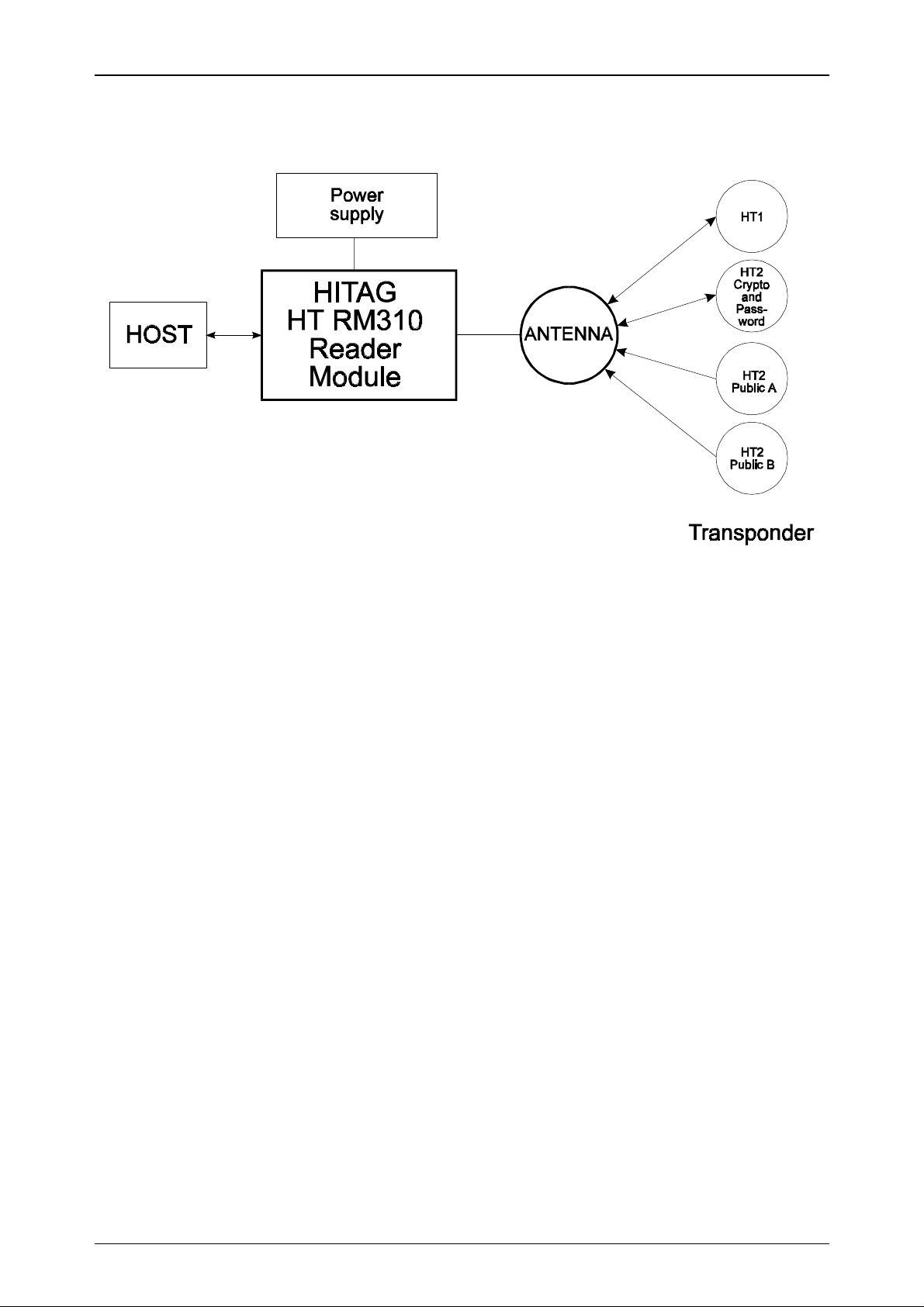
1.2. System Structure
Rev. 2.3 02-10-1998
The components shown in the diagram above are required in order to create a complete system
with the HT RM310 reader module.
Antennas of different shapes can be connected to t he module. The antennas are tuned using a capacitance and optionally a resistor. For detailed information please see Chapter 2.4.
The host system controls all actions of the reader module via a parallel interface.
The supply voltage must be a stabilized 5V DC voltage.
Htrm310.doc/HS Page 5 of 41
Page 6

02-10-1998 Rev. 2.3
2. Technical Data
2.1. General Data
HT RM310
Dimensions ( L x W x H)
Supply voltage
Power consumption:
• standard mode
• energy saving mode
Temperature range
47.3 x 28.3 x 11.4mm
5 V DC ± 5 %
(depends on the geometry of the antenna)
typ. 290 mW
20 mW
-25°C to +70 °C in operation
-40°C to +85°C when stored
Antenna
Interface
can be connected via the pin connectors
CMOS
8 Bit parallel + 2 control lines
EEPROM
10,000 write cycles
(HT RM310 only)
2.2. Dimensions of the HT RM310
15
1
16.5mm
RM2.54
47.3mm
14.7
3.3
8
25.4mm
7
28.3mm
Page 6 of 41 Htrm310.doc/HS
Page 7

HT RM310
Rev. 2.3 02-10-1998
2.3. Pin Assignment of the Male Connector
The male connector is divided into two lines. For the pin numbers please refer to the diagram
"Dimensions of the HT RM310".
Pin Number Name Function
1 /HCDA
2 /RCDA
3 /MCLR
Control signal Host data control
Control signal Reader data control
Reset entry: A reset has to be performed in case
of a voltage drop. Without this precaution, the
internal crypto unit might get irreversible damaged.
(refer to Appendix B)
4 VCC
5 GND
6 RxA
7 TxA
8D7
9D6
10 D5
11 D4
12 D3
5 V Supply voltage *
Ground
Antenna - input signal
Antenna - output signal
Data Bit 7
Data Bit 6
Data Bit 5
Data Bit 4
Data Bit 3
13 D2
14 D1
15 D0
* Only regulated voltage to be used
Data Bit 2
Data Bit 1
Data Bit 0
Htrm310.doc/HS Page 7 of 41
Page 8
02-10-1998 Rev. 2.3
HT RM310
2.4. How to Design Proximity Antennas
The antenna is an import ant part in the data transmission between the read/write device and the
t ra nsp o nd er . T hu s, whe n build ing th e ant e nna th e ins tr u ct io ns s ho uld be st r ict ly fo llo we d in o r de r
to achieve optimum results.
When deciding upon the size of the antenna the ratio between the diameter of the antenna and the
diameter o f the tra nspo nder´s c oil is fundament al. T his ra tio sho uld be within t he limits ranging
from 1 to 4. If the ratio is too big or t oo small, read/write distances may decrease and difficulties
during data transmission may occur.
2.4.1. Basics
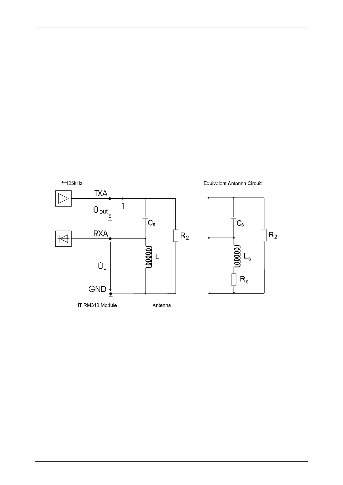
Th e fo llow ing blo c k dia gr am sh ow s t he g ene ral s tr uc tu re of a pr ox imity a nte nna and its co nne ction to the proximity read/write device.
Whe n de velo p ing an a nt enn a it is imp o rt a nt t o ta ke int o co ns ide r at io n t he limits o f t he r ea d/ w rit e
device, i.e. the maximum antenna current and the maximum voltage at the receiver input (Pin
RxA). With an output vo ltage Û
(Pin T xA ) of appr oxima tely 2 . 5Vp the follow in g limits a pply to
out
the reader module.
Maximum antenna current ( Î ) : 100 mAp
Maximum input voltage (Pin RxA, ÛL) : 32 Vp
The resistance R2 (approx. 600 ... 1000 Ω) is only needed with cables longer than 50 cm.
Page 8 of 41 Htrm310.doc/HS
Page 9

HT RM310
Rev. 2.3 02-10-1998
2.4.2. Antenna Coil
The inductance of the coil should be in the range of 350 and 500 µH.
The quality factor of the antenna should be approximately Q = 40.
fL
⋅⋅⋅2
Q
π
=
If the Q factor is too high, it must be reduced by using an additional resistor. Generally speaking it
is better to have a smaller diameter of the wire for the coil rather than using an additional resistor.
The following equation shows the approximate calculation of the number of co il windings for a
required inductance and antenna geometry:
=⋅⋅ −
La
219ln
D
R
S
a
S
.
⋅
KN
The abbreviations read as follows:
L required inductance (nH)
a circumference of the antenna (cm)
D diameter of the wire (cm)
N number of windings
K geometrical constant
circle antenna: K= 1.01
square antenna: K= 1.47
Please note:
The factor K is usually much smaller than the quotient a/D and can thus be neglected.
N
.
≈
L
aaD
⋅⋅219ln( )
Htrm310.doc/HS Page 9 of 41
Page 10
02-10-1998 Rev. 2.3
HT RM310
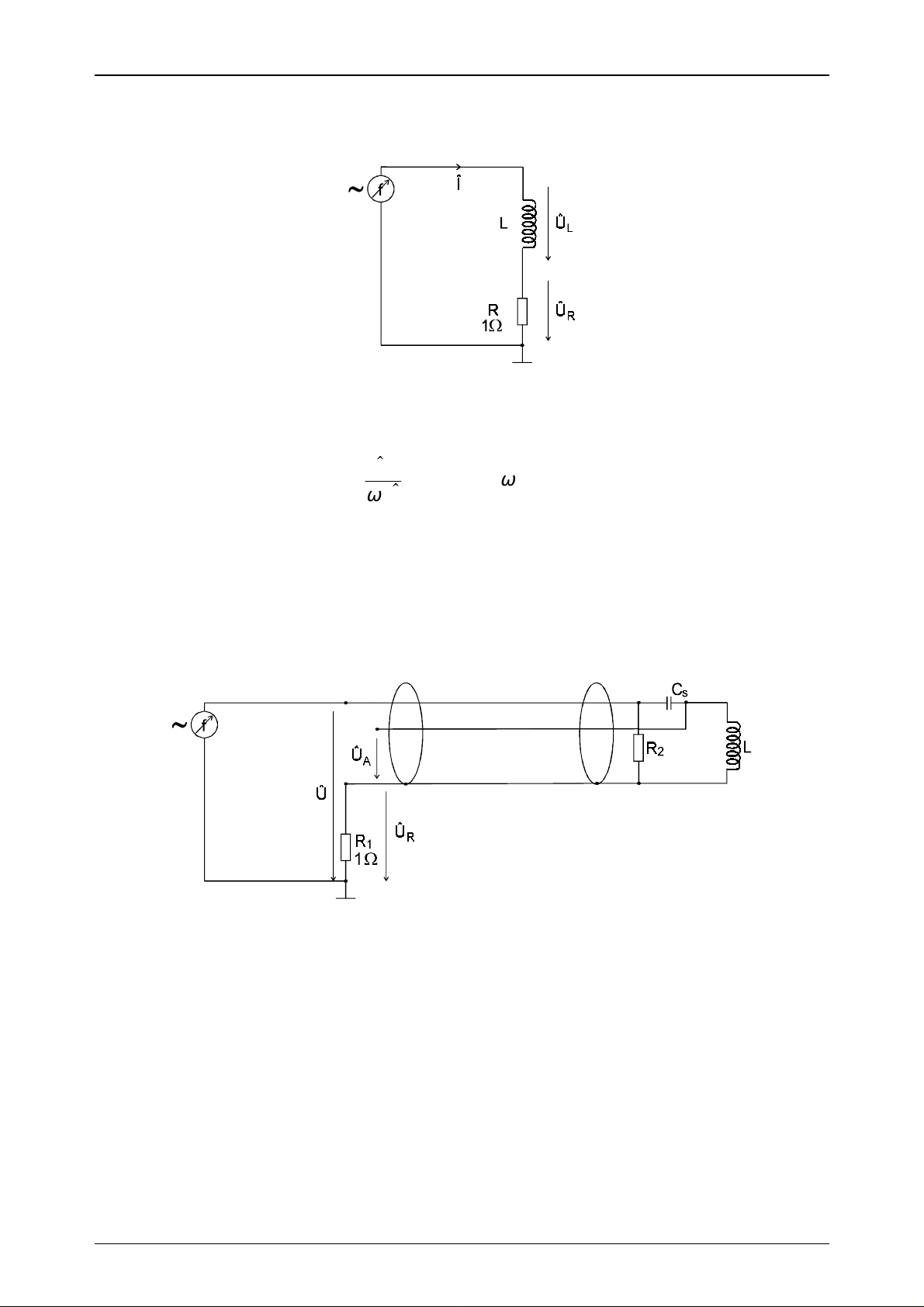
2.4.3. Measuring Inductance
The inductance of the designed coil can be determined using the following measuring procedure.
A sinus signal of 125 kHz is supplied by using a function generator. If you measure the current Î
and the antenna voltage ÛL, the inductance can be calculated according to the following formula:
U
L
L
=
I
⋅
ω
ωπ
=⋅⋅2 f
2.4.4. Antenna Tuning
The antenna has to be tuned to its final form by using the connecting cable. You must not change
anything with the antenna coil or with the connecting cable, after having finished tuning the ant e nn a . If yo u d o, t h e me c ha n ic a l c hange s w ill influenc e th e e le ctrica l v a lu e s a n d the a nten n a w ill be
detuned again.
A sinus signal of 125 kHz is fed to t he antenna connectors using a frequency generator. Now you
measure the voltages Û and ÛR wit h an os cillo sco pe . T hen c han ge t he freq ue ncy u ntil Û and Û
are in phase.
R
If the resonance frequency achieved is too high, CS has t o b e in cr e a se d . I f it is t oo lo w , CS has t o
be decreased.
The aim is to arrive at a resonance frequency of 125 kHz using CS.
The phase of impedance has to be in the range of +/- 10°.
Page 10 of 41 Htrm310.doc/HS
Page 11
HT RM310
Rev. 2.3 02-10-1998
2.4.5. Determining the Serial Resistance of the Antenna
Use an oscilloscope to measure ÛA and ÛR at a frequency of 125 kHz.
The serial resistance RS can be calculated with the following formula:
U
R
I
=
R
1
⇒ R
2.4.6. Checking the Antenna Voltage Û
L
U
A
=
S
I
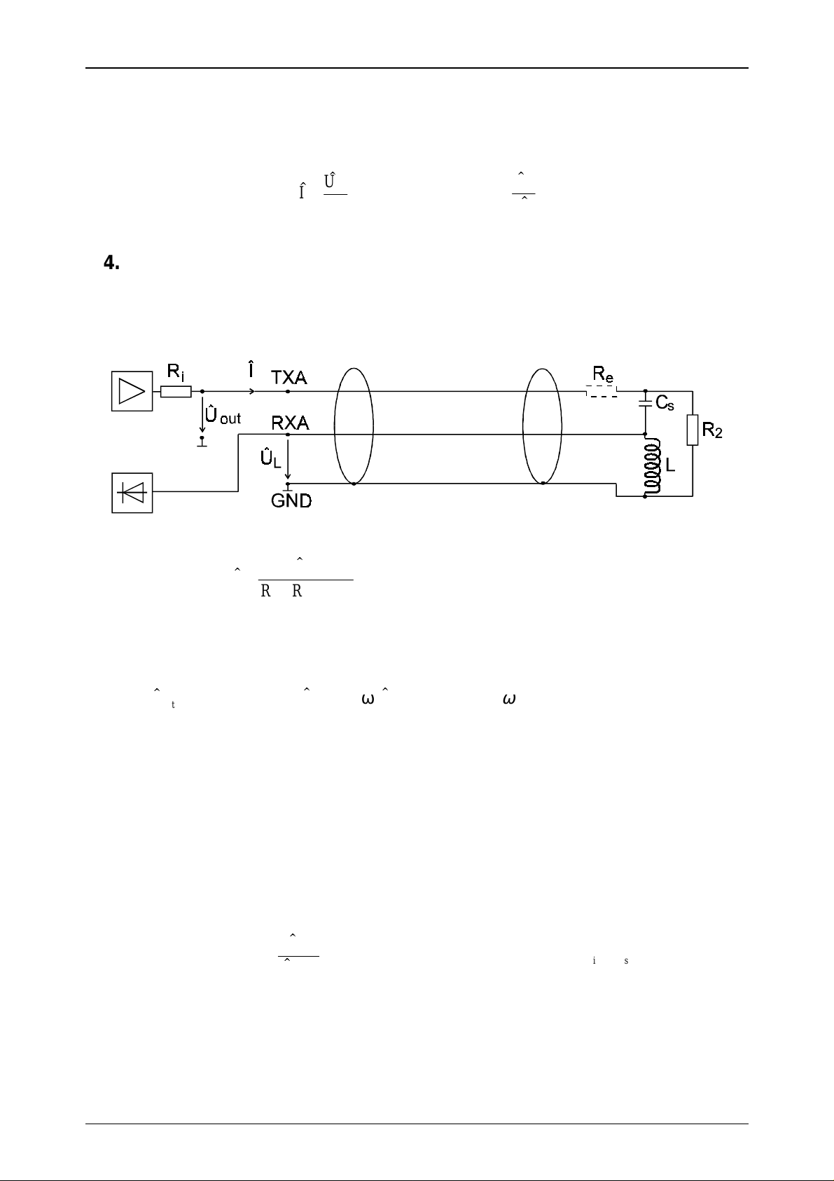
Before connecting the antenna to the read/write device (as shown in the gr aph below), you must
carry out a check calculation of the input level of the read/write device according to the formula
below in order to prevent damage.
U
I
=
RR R
out
++
is e
()
with Ri≈ 22Ω
(Ri is the internal resistance of the output amplifier)
out
≈ 25
.UVp
UL I
=⋅⋅ω
L
ωπ
=⋅⋅2 ff kHz=125
Th e ma ximu m va lu e for ÛL is 32 Vp. Based on this calculation damage is avoided at the receiver
input (Pin RxA) of the read/write device.
With ÛL < 32 Vp the resistor Re can be omitted.
With ÛL > 32 Vp you have to calculate and insert Re according to the following formula:
U
RL
=⋅⋅ − −
e
ω
U
out
L
max
RR
is
⇒
RL RR
≥⋅⋅ − −
ω
eis
0 078,
with Ri≈ 22Ω
Htrm310.doc/HS Page 11 of 41
Page 12

02-10-1998 Rev. 2.3
HT RM310
2.4.7. Procedure for Practical Antenna Design
The procedure how to design a HITAG Proximity antenna has been described in the previous
chapters. Generally speaking the following steps have to be considered:
1. The required antenna inductance can be chosen in the range of 350µH and 500µH
(e.g. L=420µH).
2. The number of turns N can be calculated with the following formula:
LnH
N
.
=
219ln ( )
for L=420µH:
N
=
19
.
420000
⋅⋅⋅ −
aaDK aaD
2
ln ( ) ln( )
Please note:
Usually the factor K is much smaller than the quotient from a/D and can thus be neglected.
3. No w the antenna can be build according to t he required dimensio ns (circumference a) with the
calculated number of turns.
Please note:
The antenna coil must not be changed afterwards because with the mechanical dimensio ns the
electrical specifications are changing, too. That means the number of turns, the shape, the arrangement of the coil windings and the antenna supply cable must be used in their final form.
Please note:
Metal influences considerably the electric characteristics of the antenna. If metal is close to t he
antenna when it is set up, all instructions below must be followed (distance from
metal < maximum diameter of the antenna).
4. Measuring the inductance L of the antenna is described in Chapter 2.4.3.
5. Determination of the serial capacitor CS is described in Chapter 2.4.4.
Please note:
The capacitance of the antenna supply cable can be determined according to the specifications
given in the data sheet of the cable (e.g. Cp = 180 pF/m).
6. Now the antenna has to be tuned according to the instructions given in Chapter 2.4.4.
The tuning of the antenna is finished when the phase of impedance is within the range of
+/- 10°.
7. The serial resistance Rs of the antenna is the impedance of the tuned antenna and is an ohms
resistance at the resonance frequency ( f=125 kHz). It can be calculated acco rding t o the formula given in Chapter 2.4.5.
[]
⋅⋅⋅ −
aaDK
19
633
.
⋅
=
Page 12 of 41 Htrm310.doc/HS
Page 13

HT RM310
Rev. 2.3 02-10-1998
8. In order to achieve a satisfactory reading distance, the quality factor of the antenna coil (for
non-metal environment) should be approximately Q = 40.
The quality factor of the coil is calculated as follows:
Q
L
⋅
ωπ
=
=
R
SS
⋅⋅⋅
2
R
fL
9. By knowing Rs and the dropping resist or (Ri = 22Ω) the current Î and the antenna voltage Û
can be calculated. It is very import ant to calculate t he antenna voltage before connecting the
antenna to the HT RM310 module to avoid damage. If the calculated value of ÛL is higher than
ÛL =32 Vp, a resistor Re must be used to protect the receiver input.
The resistor has to be placed as shown in Chapter 2.4.6.
10. After having checked the antenna voltage as described in point 9, connect your antenna to t he
HT RM310 mo dule and measure the read/write distances with your transponders. Should the
read/write distances not meet your expectations, the following points should be considered:
L
The size of the antenna and the size of the transponder have to be in a defined ratio (between
•
4 and 1).
That means if you increase the antenna beyo nd a certain size, t he maximum read/write distances will decrease when using the same transponder.
The optimal shape of the antenna coil is a circle, while the performance of a square shaped
•
coil is much better than that of a rectangular one (with the same circumference).
In order t o achieve better r ead/write distances the quality fact or of the antenna coil should
•
be increased, but must not be higher than Q=40. This can be attained with the following
measures:
All conducting material has to be removed from the antenna environment.
−
A thicker wire can be used for the coil.
−
Ferrite can be placed behind the antenna coil to concentrate the field.
−
Extension of the antenna area.
−
Also with a different number of turns better results can be achieved.
−
Attention:
The above measures must not differ from the antenna design instructions of Chapter 2.4.
Htrm310.doc/HS Page 13 of 41
Page 14

02-10-1998 Rev. 2.3
HT RM310
3. Interface HT RM310 ⇔ Host
Communication with the host is carried out via an 8 Bit parallel interface with two control lines.
3.1. General Definitions
3.1.1. Hardware
The interface needs in total 10 lines (8 data lines and 2 control lines). The data lines are bidirectional, while the contr ol lines are unidirectional. The control lines from host to r eader module
(host co ntro l data /HCDA) and from reader module to host (reader cont ro l data /RCDA ) are low
active. By activating the control line either the host or t he reader module indicate that dat a is on
the data line. The respective counter part set s its control line to LOW for a shor t period of time,
while the rising ramp of the control line indicates that the data transmission has been finished.
8 Bit Data
Host Data Host Data Host Data ReaderData ReaderData
HCDA
RCDA
Graph: Timing diagram
A bus conflict can never occur, since communication is always initiated by the host . The reader
module responds upon the request command of the host, while the host has to wait for the response of the reader module. If the reader module does not respond within the specified time of 1s
fo r this co mma nd ( s ee a pp e nd ix A: T iming I n t er face) , a time out occurs and t he host start s again
with a request.
Since bot h the host and the reader module can send data, t he data lines should only be oper ated
when also the respective control line indicates data.
Page 14 of 41 Htrm310.doc/HS
Page 15

HT RM310
Rev. 2.3 02-10-1998
3.1.2. Structure of the Protocol
The protocol is structured according to the following format:
Byte 1 2 ... n-1
Function Command/Status Data ... Data
Command / Status Contains either the command number of the command to be executed or
the status message for the command to be executed.
Please refer to the appendix for the structure of the command/status byte.
Data Data is transmitted binary, t hat means characters between 0x00 and 0xFF
are allowed. Data is only transmitted when the command requires the
transmission of data.
Htrm310.doc/HS Page 15 of 41
Page 16

02-10-1998 Rev. 2.3
3.2. Set of Commands
The commands can be divided into five different sets:
1) HITAG 1 Read/Write Commands
2) HITAG 2 Read/Write Commands
3) Public Mode Read Commands
4) General Commands
5) Commands for Personalization
3.2.1. HITAG 1 Read/Write Commands
Name of command Function
GetSnr_HT1 Reads serial number
GetSnr_HT1_A Reads serial number in advanced mode
SelectSnr_HT1 Selects transponder
SelectLastSnr_HT1 Selects transponder with serial number read with last GetSnr_HT1
HaltSelected_HT1 Sets transponder in halt mode
ReadPage_HT1_P Reads a page in plain mode
ReadPage_HT1_C Reads a page in encrypted mode
WritePage_HT1_P Writes a page in plain mode
WritePage_HT1_C Writes a page in encrypted mode
ReadBlock_HT1_P Reads a block in plain mode
ReadBlock_HT1_C Reads a block in encrypted mode
WriteBlock_HT1_P Writes a block in plain mode
WriteBlock_HT1_C Writes a block in encrypted mode
MutualAuthent_HT1 Carries out a full authentication procedure
HT RM310
3.2.2. HITAG 2 Read/Write Commands
Name of command Function
GetSnr_HT2_P Selects transponder and reads serial number in Password Mode
GetSnr_HT2_C Selects transponder and reads serial number in Crypto Mode
HaltSelected_HT2 Sets transponder in halt mode
ReadPage_HT2 Reads a page
ReadPageInv_HT2 Reads a Bit inverted page
WritePage_HT2 Writes a page (with single inversion of the address)
3.2.3. Public Modes
Name of command Function
ReadPublic A Reads Page 4 and 5 of HT2 in Public Mode A
ReadPublic B Reads Page 4 to 7 of HT2 in Public Mode B
Page 16 of 41 Htrm310.doc/HS
Page 17

HT RM310
Rev. 2.3 02-10-1998
3.2.4. General Commands
Name of command Function
HF_OFF Deactivates the RF field.
The RF field is activated with any comman d or with each LOW signal generated by
/HCDA.
Power Down Sets the entire module into sleep mode.
The sleep mode is deactivated by any command or LOW signal of /HCDA.
GetVersion Displays the software version.
3.2.5. Commands for Personalization
Name of command Function
WriteSecret_HT Writes Keys, Logdata and Password into the EEPROM.
Htrm310.doc/HS Page 17 of 41
Page 18

02-10-1998 Rev. 2.3
HT RM310
3.3. Description of the Commands
3.3.1. GetSnr_HT1
This command reads the serial number of a HITAG 1 transponder in “Standard Protocol Mode“.
Protocol:
Host - Reader module
0x10
Reader module - Host
status
Snr [0]
Snr [3]
status: 0 no error
1 INTERFACE error
3 NOTAG error
3.3.2. GetSnr_HT1_Adv
This command reads t he serial number of a HITAG 1 transponder and switches the transponder
into “Advanced Protocol Mode“. The transponder now responds on all commands in the
“Advanced Prot ocol Mode“. This mode can only be left by an “power on reset“ of t he transponder
(use “HF_OFF“ or “Power Do wn“ command or move the transponder out of the antenna field).
The “Advanced Protocol Mode“ is not left by using the “GetSnr_HT1“.
The major difference between “Standard Pro tocol Mode“ and “Advanced Protoco l Mode“ is incr ea se d d at a re liabilit y d ur ing da t a t r ans miss io n fro m t he t ra ns po nd er t o th e r e ad er by usin g an 8
Bit CRC and a longer start sequence.
The “Advanced Protocol Mode“ is not supported by transponder version HT1 ICS30 01x, but
only by version HT1 ICS30 02x with serial numbers 0x y5yyyyyy
Protocol:
Host - Reader module
Reader module - Host
0x11
status
Snr [0]
Snr [3]
status: 0 no error
1 INTERFACE error
3 NOTAG error
Page 18 of 41 Htrm310.doc/HS
Page 19

HT RM310
Rev. 2.3 02-10-1998
3.3.3. SelectSnr_HT1
This command selects a HITAG 1 transponder with the serial number given in the pro to col. With
this selection the transponder is prepared for read and write commands in HITAG 1 mode.
The command provides the OTP of the selected transponder. Using the “Advanced Protocol
Mode“ of HITAG 1 transponders by using the “GetSnr_HT1_Adv“ command the data is followed
by an 8 Bit CRC.
Protocol:
Host - Reader module
0x12
Snr [0]
Snr [3]
Reader module - Host
status
OTP [0] LSB
OTP [3] MSB
status: 0 no error
1 INTERFACE error
3 NOTAG error
3.3.4. SelectLastSnr_HT1
This command selects a HITAG 1 tr ansponder with the serial number read by t he last error free
command “GetSnr_HT1“. There must be no reset of the tr ansponder (caused by the commands
“HF-OFF“, “Powerdown“ or by moving the transponder out of the antenna field) between the
commands “GetSnr_HT1“ and “SelectLastSnr_HT1“
With this selection the transponder is prepared for read and write commands in HITAG 1 mode.
The command provides the OTP of the selected tr anspo nder. I n t he “Advanced Protocol Mode“ of
HITAG 1 transponders (by using the “GetSnr_HT1_Adv“-command) the data is followed by an 8
Bit CRC.
Protocol:
Host - Reader module
Reader module - Host
Htrm310.doc/HS Page 19 of 41
0x13
status
OTP [0] LSB
OTP [3] MSB
status: 0 no error
1 INTERFACE error
3 NOTAG error
Page 20

02-10-1998 Rev. 2.3
HT RM310
3.3.5. HaltSelected_HT1
Se ts t he selec te d tr ans pon der in halt mod e, i. e. the tr ansp ond er is mut ed u nt il it h as le ft t he RF
field or until the RF field is deactivated. By using this co mmand different transponders can be handled simultaneously in the operating field of the antenna.
Protocol:
Host - Reader module
0x14
Reader module - Host
status
status: 0 no error
1 INTERFACE error
8 ACKNOWLEDGEMENT error
3.3.6. ReadPage_HT1_P / ReadPage_HT1_C
Reads a page of the selected transponder.
The command “ReadPage_HT1_P“ reads plain areas of the HITAG 1 transponders only.
Reading encrypted areas of the HITAG 1 transponder with this command leads to a status
“NOTAG error“ and the transponder is reset.
To read encrypted areas of the transponders use the command “ReadPage_HT1_C“.
Access to the secret area is only possible in Crypto Mode after a mutual authentication.
In the “Advanced Protoco l Mo de“ of HITAG 1 t ransponders (by using the “GetSnr_HT1_Adv“command) the data is followed by an 8 Bit CRC.
Protocol:
Host - Reader module
Reader module - Host
0x15 / 0x16
pagenr
status
data[0]
data[3]
status: 0 no error
1 INTERFACE error
3 NOTAG error
9 CRYPTOBLOCK NOT INIT
Page 20 of 41 Htrm310.doc/HS
Page 21

HT RM310
Rev. 2.3 02-10-1998
3.3.7. ReadBlock_HT1_P / ReadBlock_HT1_C
Reads a block (up to 4 pages) of the selected transponder.
The command “ReadBlock_HT1_P“ reads plain areas of the HITAG 1 transponders only.
Reading encrypted areas of the HITAG 1 transponder with this command leads to a status
“NOTAG error“ and the transponder is reset.
To read encrypted areas of the transponders use the command “ReadBlock_HT1_C“.
Access to the secret area is only possible in Crypto Mode after a mutual authentication.
In the “Advanced Protoco l Mo de“ of HITAG 1 t ransponders (by using the “GetSnr_HT1_Adv“command) the data is followed by an 8 Bit CRC.
With the command ”ReadBlock_HT1_P“ resp. ”ReadBlock_HT1_C“ data beginning from the
st a r t ad d r es s ( pa g e nu mb er ) till t h e e nd o f t he b lo ck c an be r ea d . D ep e nd ing o n the star t a d d r es s
4, 8, 12 or 16 Bytes are provided by the reader module.
Protocol:
Host - Reader module
Reader module - Host
0x17 / 0x18
pagenr
status
data[0]
data[n]
n = 4, 8, 12, 16
status: 0 no error
1 INTERFACE error
3 NOTAG error
9 CRYPTOBLOCK NOT INIT
Htrm310.doc/HS Page 21 of 41
Page 22

02-10-1998 Rev. 2.3
HT RM310
3.3.8. WritePage_HT1_P / WritePage_HT1_C
Writes a page of the selected transponder.
Writing to encrypted areas of the HITAG 1 transponder with this command leads to a status
“NOTAG error“ and the transponder is reset.
To write to encrypted areas of the transponders use the command “WritePage_HT1_C“.
Access to the secret area is only possible in Crypto Mode after a mutual authentication.
Upon completion of the write command, a “Read after Write“ procedure should be carried out in
order to check whether the write access was successful.
Protocol:
Host - Reader module
Reader module - Host
0x19 /0x1A
pagenr
data[0]
data[3]
status
status: 0 no error
1 INTERFACE error
3 NOTAG error
4 TIMEOUT error
9 CRYPTOBLOCK NOT INIT
Page 22 of 41 Htrm310.doc/HS
Page 23

HT RM310
Rev. 2.3 02-10-1998
3.3.9. WriteBlock_HT1_P / Write Block_HT1_C
Writes a block (up to 4 pages) of the selected transponder.
Writing to encrypted areas of the HITAG 1 transponder with this command leads to a status
“NOTAG error“ and the transponder is reset.
To write to encrypted areas of the transponders use the command “WriteBlock_HT1_C“.
Access to the secret area is only possible in Crypto Mode after a mutual authentication.
With the command ”WriteBlock_HT1_P“ resp. ”WriteBlock_HT1_C“ data beginning from the
st ar t ad d re ss ( p ag e nu mbe r ) t ill t he e nd o f t he b loc k c an be w r itt e n. De pe ndin g o n t he st ar t a ddress 4, 8, 12 or 16 Bytes are written with one command to the transponder.
Upon completion of the write command, a “Read after Write“ procedure should be carried out in
order to check whether the write access was successful.
Protocol:
Host - Reader module
Reader module - Host
0x1B / 0x1C
pagenr
data[0]
data[n]
n = 4, 8, 12, 16
status
status: 0 no error
1 INTERFACE error
3 NOTAG error
4 TIMEOUT error
9 CRYPTOBLOCK NOT INIT
Htrm310.doc/HS Page 23 of 41
Page 24

02-10-1998 Rev. 2.3
HT RM310
3.3.10. MutualAuthent_HT1
This command carries out the full authentication procedure of the transponder and the reader
module.
After this authentication areas in encrypted mode can be accessed resp. encrypted commands can
be used in the communication with the transponder.
The transponder exits encrypted mode if a not encrypted command, a “GetSnr_HT1“ or
“GetSnr_HT1_Adv“ command is used or if the transponder is reset (caused by the commands
“HF-OFF“, “Powerdown“ or by moving the transponder out of the antenna field).
Using the Byte “loginfo“ you can choose between Log information (Keys and Logdata) A or B
Protocol:
Host - Reader module
Reader module - Host
0x1D
loginfo
loginfo: 0x00 loginfo A
0x02 loginfo B
status
status: 0 no error
1 INTERFACE error
7 AUTHENT error
Page 24 of 41 Htrm310.doc/HS
Page 25

HT RM310
Rev. 2.3 02-10-1998
3.3.11. GetSnr_HT2_P
This command selects a HITAG 2 transponder in Password Mode. With this selection the
transponder is prepared for read and write commands in HITAG 2 Password Mode.
For the selection in Password Mode, a passwor d is transmitted to the reader module which must
correspond to Page 1 on the transponder (Password RWD). After the command has been executed, t he reader module returns the serial number and the co ntent of Page 3 (configbyt e with 24
Bit Password TAG).
When t he transponder is in Crypt o Mo de, no selection occurs and only t he serial number and the
status message "Password RWD error" are returned.
If t he tr ans po nde r is set in o ne o f t he p ublic mod es , it ca n o nly be se lect ed wit hin 2. 56 ms a fte r
reset (entering the RF field or activating the RF field).
Protocol:
Host - Reader module
Reader module - Host
0x0A
Password [0]
Password [3]
status
Snr [0]
Snr [3]
configbyte
Password TAG [0]
Password TAG [2]
status: 0 no error
1 INTERFACE error
3 NOTAG error
5 PASSWORD RWD error
Htrm310.doc/HS Page 25 of 41
Page 26

02-10-1998 Rev. 2.3
HT RM310
3.3.12. GetSnr_HT2_C
This command selects a HITAG 2 transponder in Crypt o Mode. With this selection the transponder is prepared for read and write commands in HITAG 2 Crypto Mode.
After the command has been executed, the reader module returns the serial number and the co ntent of the configbyte.
When a transponder in Password Mo de receives the command "GetSnr_HT2_C", only the serial
number and the status message "Password RWD error" are returned.
If t he tr ans po nde r is set in o ne o f t he p ublic mod es , it ca n o nly be se lect ed wit hin 2. 56 ms a fte r
reset (entering the RF field or activating the RF field).
Protocol:
Host - Reader module
Reader module - Host
0x0B
status
Snr [0]
Snr [3]
configbyte
Password TAG [0]
Password TAG [2]
status: 0 no error
1 INTERFACE error
3 NOTAG error
7 AUTHENT error
Page 26 of 41 Htrm310.doc/HS
Page 27

HT RM310
Rev. 2.3 02-10-1998
3.3.13. HaltSelected_HT2
Se ts t he selec te d tr ans pon der in halt mod e, i. e. the tr ansp ond er is mut ed u nt il it h as le ft t he RF
field or until the RF field is deactivated. By using this co mmand different transponders can be handled simultaneously in the operating field of the antenna.
Protocol:
Host - Reader module
Reader module - Host
0x0C
status
status: 0 no error
1 INTERFACE error
8 ACKNOWLEDGEMENT error
3.3.14. ReadPage_HT2
Reads a page of the selected transponder. I n order to increase data security this command should
always be combined with the command ReadPageInv_HT2. Then the data which has been read
with ReadPage_HT2 and ReadPageInv_HT2 should be compared with each other.
Protocol:
Host - Reader module
0x0D
pagenr
Reader module - Host
status
data [0]
data [3]
status: 0 no error
1 INTERFACE error
3 NOTAG error
Htrm310.doc/HS Page 27 of 41
Page 28

02-10-1998 Rev. 2.3
HT RM310
3.3.15. ReadPageInv_HT2
Reads a Bit inverted page of the selected transponder. This command increases the data security
and should always be combined with the command ReadPage_HT2. Then the data which has been
read with ReadPageInv_HT2 and ReadPage_HT2 should be compared with each other.
Protocol:
Host - Reader module
0x0E
pagenr
Reader module - Host
status
data [0]
data [3]
status: 0 no error
1 INTERFACE error
3 NOTAG error
3.3.16. WritePage_HT2
Writes a page of the selected transponder.
Upon completion of the write command, "Read after Write" should be carried out in order to
check whether the write command was successful.
Please note: The address is transmitted both non-inverted and inverted to the transponder.
Protocol:
Host - Reader module
Reader module - Host
0x0F
pagenr
data [0]
data [3]
status
status: 0 no error
1 INTERFACE error
3 NOTAG error
4 TIMEOUT error
Page 28 of 41 Htrm310.doc/HS
Page 29

HT RM310
Rev. 2.3 02-10-1998
3.3.17. ReadPublic A
Reads a transponder in Public A Mode. The coding of the data area must contain a header and the
parity struct ure of the µE M H400x. Only t he 40 Bit (5 byte) information of the µ EM H400x data
(1 byte customer ID; 4 byte user ID) is transmitted.
Protocol:
Host - Reader module
Reader module - Host
0x07
status
customer ID
user ID [0]
user ID [3]
status: 0 no error
1 INTERFACE error
3.3.18. ReadPublic B
Reads a transponder in Public B Mode. The coding of the data areas must, however, have a header
according to ISO 11785. 13 byte (8 byte identification code, 2 byte CRC, 3 byte extension) are
transmitted.
Protocol:
Host - Reader module
0x08
Reader module - Host
status
data [0]
data [7]
CRC [0]
CRC [1]
Extension [0]
Extension [2]
status: 0 no error
1 INTERFACE error
Htrm310.doc/HS Page 29 of 41
Page 30

02-10-1998 Rev. 2.3
HT RM310
3.3.19. HF-OFF
Deactivates the RF field of the antenna. When receiving the next command (/HCDA) the RF field
is automatically activated again.
Protocol:
Host - Reader module
Reader module - Host
0x01
status
status: 0 no error
1 INTERFACE error
3.3.20. Powerdown
This command sets the complete reader module into sleep mode. When receiving the next command (/HCDA) the reader module is automatically set into operating mode.
Protocol:
Host - Reader module
Reader module - Host
0x02
status
status: 0 no error
1 INTERFACE error
3.3.21. GetVersion
Reads the software version of the reader module.
Protocol:
Host - Reader module
Reader module - Host
0x03
status
Version - overview
Version - in detail
reserved
reserved
status: 0 no error
1 INTERFACE error
Page 30 of 41 Htrm310.doc/HS
Page 31

HT RM310
Rev. 2.3 02-10-1998
3.3.22. WriteSecret_HT
Using this command the reader module receives the data needed for the secret access to the
HITAG transponders. The data is stored "write only" in the internal EEPROM of the Crypto
Processor.
In order to change the data, the value of the current data has to be transmitted first to the reader
module. The individual dat a areas of the secret access data are changed one after ano ther and t he
module returnes “no error“ statusbytes(0x00) for each matching data couple (old and new data).
The personalizat ion process is interrupt ed if the comparison of old and new data prove inconsistent. The module then returnes the according status for the data couple that does not match.
Please Note : To successfully change the secret data you have t o complete the whole proce-
dure step by step as shown in the following protocol description.
In case of an error the host has to cancel the personalization procedure.
Protocol:
Host - Reader module
Reader module - Host
Host - Reader module
0x00
old Key A [0]
old Key A [3]
new Key A [0]
new Key A [3]
status
status: 0 no error
1 INTERFACE error
80 Wrong Crypto
81 Wrong old Key A
0x00
old Key B [0]
old Key B [3]
new Key B [0]
Reader module - Host
Htrm310.doc/HS Page 31 of 41
new Key B [3]
status
status: 0 no error
1 INTERFACE error
80 Wrong Crypto
82 Wrong old Key B
Page 32

02-10-1998 Rev. 2.3
HT RM310
Host - Reader module
Reader module - Host
Host - Reader module
0x00
old Logdata 0A [0]
old Logdata 0A [3]
new Logdata 0A [0]
new Logdata 0A [3]
status
status: 0 no error
1 INTERFACE error
80 Wrong Crypto
83 Wrong old Logdata 0A
0x00
old Logdata 0B [0]
old Logdata 0B [3]
new Logdata 0B [0]
Reader module - Host
Host - Reader module
Reader module - Host
new Logdata 0B [3]
status
status: 0 no error
1 INTERFACE error
80 Wrong Crypto
84 Wrong old Logdata 0B
0x00
old Logdata 1A [0]
old Logdata 1A [3]
new Logdata 1A [0]
new Logdata 1A [3]
status
status: 0 no error
1 INTERFACE error
80 Wrong Crypto
85 Wrong old Logdata 1A
Page 32 of 41 Htrm310.doc/HS
Page 33

HT RM310
Rev. 2.3 02-10-1998
Host - Reader module
Reader module - Host
Host - Reader module
0x00
old Logdata 1B [0]
old Logdata 1B [3]
new Logdata 1B [0]
new Logdata 1B [3]
status
status: 0 no error
1 INTERFACE error
80 Wrong Crypto
86 Wrong old Logdata 1B
0x00
old HT2 Key 16 [0]
old HT2 Key 16 [3]
new HT2 Key 16 [0]
Reader module - Host
Host - Reader module
Reader module - Host
new HT2 Key 16 [3]
status
status: 0 no error
1 INTERFACE error
80 Wrong Crypto
87 Wrong old HITAG 2 Key 16
0x00
old HT2 Key 32 [0]
old HT2 Key 32 [3]
new HT2 Key 32 [0]
new HT2 Key 32 [3]
status
status: 0 no error
1 INTERFACE error
80 Wrong Crypto
88 Wrong old HITAG 2 Key 32
Htrm310.doc/HS Page 33 of 41
Page 34

02-10-1998 Rev. 2.3
4. Appendix A:
Timing Interface
Host → HT RM310-Module (Receive Mode):
HDCA
RCDA
t
RLR
HT RM310
t
RHR
t
w
HT RM310-Module → Host (Transmit Mode):
RCDA
HCDA
t
RLT
t
w
t
RHT
Time Description min. typ. max.
t
RLR
t
RHR
t
RLT
t
RHT
t
W
wait for RCDA Low in Receive Mode
wait for RCDA High in Receive Mode
wait for RCDA Low in Transmit Mode
wait for RCDA High in Transmit Mode
25 µs
17 µs
15 µs
20 µs
wait for Host 5µs 50 ms
Note: The max. time corresponds to the time-out
t
w
1 s
1 s
t
w
Page 34 of 41 Htrm310.doc/HS
Page 35

HT RM310
Rev. 2.3 02-10-1998
5. Appendix B: Application Example
The figure below shows an example of a standard application wit h the HT RM310 Mini Reader
Module connected to a host.
To avoid destruction of the int ernal EEPROM dat a in case of powerfailur e a power supervisory
circuit to monitor the supply voltage is required.
Htrm310.doc/HS Page 35 of 41
Page 36

02-10-1998 Rev. 2.3
6. Appendix C: Reaction Times of the Reader Module
HT RM310
Action min. typ. max. unit
GetSnr_HT2_P 3
1)
36
2)
ms
ReadPage_HT2 16,5 ms
WritePage_HT2 23 25 ms
Halt_HT2 10,5 ms
GetSnr_HT2_C 3
1)
98 ms
ReadPage_HT2 ( Crypto ) 32 ms
WritePage_HT2 ( Crypto ) 43 ms
Halt_HT2 (Crypto) 18 ms
WriteSecret_HT 425 ms
Read Public Mode A
Read Public Mode B
GetSnr_HT1 3,5
GetSnr_HT1_A 3,5
3)
3)
33 65 ms
40 70 ms
1)
1)
22
23
2)
2)
ms
ms
SelectSnr_HT1 (Standard) 21 ms
SelectSnr_HT1 (Advanced) 25 ms
SelectLastSnr_HT1 (Standard) 21 ms
SelectLastSnr_HT1 (Advanced) 25 ms
HaltSelected_HT1 (Standard) 9 ms
HaltSelected_HT1 (Advanced) 10 ms
ReadPage_HT1_P (Standard) 16,5 ms
ReadPage_HT1_P (Advanced) 20 ms
ReadPage_HT1_C (Standard) 32,5 ms
ReadPage_HT1_C (Advanced) 38,5 ms
ReadBlock_HT1_P (Standard)
ReadBlock_HT1_P (Advanced)
ReadBlock_HT1_C (Standard)
ReadBlock_HT1_C (Advanced)
4)
4)
4)
4)
41 ms
45,5 ms
86 ms
94 ms
WritePage_HT1_P (Standard) 28 30 ms
WritePage_HT1_P (Advanced) 29 31 ms
WritePage_HT1_C (Standard) 45 ms
WritePage_HT1_C (Advanced) 49 ms
WriteBlock_HT1_P (Standard)
WriteBlock_HT1_P (Advanced)
WriteBlock_HT1_C (Standard)
WriteBlock_HT1_C (Advanced)
4)
4)
4)
4)
85 92 ms
87 94 ms
144 ms
146 ms
MutualAuthent_HT1 (Standard) 70 ms
MutualAuthent_HT1 (Advanced) 74 ms
1) no transponder in antenna field
2) transponder in antenna field
3) transponder already in antenna filed
4) 4 Pages
Timing for HITAG 1 is valid for HT1 ICS30 with serial numbers 0x y5yyyyyy only.
Page 36 of 41 Htrm310.doc/HS
Page 37

HT RM310
7. Appendix D:
List of Command Bytes
Hex Value Command
0x00 WriteSecret_HT
0x01 HF_OFF
0x02 Power down
0x03 GetVersion
0x07 ReadPublic A
0x08 ReadPublic B
0x0A GetSnr_HT2_P
0x0B GetSnr_HT2_C
0x0C HaltSelected_HT2
0x0D ReadPage_HT2
0x0E ReadPageInv_HT2
0x0F WritePage_HT2
Rev. 2.3 02-10-1998
0x10 GetSnr_HT1
0x11 GetSnr_HT1_A
0x12 SelectSnr_HT1
0x13 SelectLastSnr_HT1
0x14 HaltSelected_HT1
0x15 ReadPage_HT1_P
0x16 ReadPage_HT1_C
0x17 ReadBlock_HT1_P
0x18 ReadBlock_HT1_C
0x19 WritePage_HT1_P
0x1A WritePage_HT1_C
0x1B WriteBlock_HT1_P
0x1C WriteBlock_HT1_C
0x1D MutualAuthent_HT1
Htrm310.doc/HS Page 37 of 41
Page 38

02-10-1998 Rev. 2.3
8. Appendix E:
List of Status Bytes
Hex Value Status
0x00 no error
0x01 Interface error
0x03 NOTAG error
0x04 TIMEOUT error
0x05 Password RWD error
0x07 AUTHENT error
0x08 ACKNOWLEDGEMENT error
0x09 CRYPTOBLOCK NOT INIT
0x80 Wrong crypto
0x81 Wrong old Key A
0x82 Wrong old Key B
0x83 Wrong old Logdata 0A
0x84 Wrong old Logdata 0B
0x85 Wrong old Logdata 1A
0x86 Wrong old Logdata 1B
0x87 Wrong old Key 16
0x88 Wrong old Key 32
HT RM310
Page 38 of 41 Htrm310.doc/HS
Page 39

HT RM310
Meaning of the status bytes:
Rev. 2.3 02-10-1998
no error:
INTERFACE error:
NOTAG error:
TIMEOUT error:
PASSWORD RWD error:
AUTHENT error:
ACKNOWLEDGEMENT error:
Command executed correctly.
− No proper communication between reader module and
host.
− Unknown command byte.
No transponder in the antenna field or transponder already
selected.
Transponder out of writing distance, not enough energy to
write on the transponder.
HT2 was accessed using a wrong Password RWD.
An error occurred during the authentication process.
− Keys or Logdata of the transponder and the crypto proces-
sor prove inconsistent.
− faulty crypto processor.
− no crypto processor existing.
The acknowledgement of the transponder on a HALTcommand was not received correctly.
CRYPTOBLOCK NOT INIT
Wrong Crypto:
Wrong old Key A:
Wrong old Key B:
Wrong old Logdata 0A:
Wrong old Logdata 0B:
Wrong old Logdata 1A:
Wrong old Logdata 1B:
Wrong old HT2 Key 16:
A cryptographic command was transmitted without authentication.
Faulty crypto processor. This status is returned only after the
personalization command. All other commands return
"AUTHENT error".
Error writing Key A (on comparison old data and new data
prove inconsistent)
Error writing Key B
Error writing Logdata 0A
Error writing Logdata 0B
Error writing Logdata 1A
Error writing Logdata 1B
Error writing Key 16
Wrong old HT2 Key 32:
Htrm310.doc/HS Page 39 of 41
Error writing Key 32
Page 40

02-10-1998 Rev. 2.3
9. Appendix F:
List of KEYS in the Crypto Processor
The crypto processor is delivered with the following key set:
Secret Data Hex Value
HT1 Key A 00 00 00 00
HT1 Key B 00 00 00 00
HT1 Logdata 0A 00 00 00 00
HT1 Logdata 0B 00 00 00 00
HT1 Logdata 1A 00 00 00 00
HT1 Logdata 1B 00 00 00 00
HT2 Key 16 20 20 4F 4E
HT2 Key 32 4D 49 4B 52
HT RM310
Page 40 of 41 Htrm310.doc/HS
Page 41

Philips Semiconductors - a worldwide company
Argentina
Australia
Tel. +612 9805 4455, Fax. +612 9805 4466
Austria
Tel. +431 60 101, Fax. +431 30 101 1210
Belarus
220050 MINSK, Tel. +375172 200 733, Fax. +375172 200 773
Belgium
Brazil
Bulgaria
51 James Bourchier Blvd., 1407 SOFIA Tel. +4822 612 2831, Fax. +4822 612 2327
Tel. +3592 689 211, Fax. +3592 689 102
Canada
Tel. +1800 234 7381
China/Hong Kong
72 Tat Chee Avenue, Kowloon Tong, HONG KONG,
Tel. +85223 19 7888, Fax. +85223 19 7700 Tel. +65350 2538, Fax. +65251 6500
Colombia
Czech Republic
Denmark
Tel. +4532 88 2636, Fax. +4531 57 1949 2092 JOHANNESBURG, P.O.Box 7430 Johannesburg 2000,
Finland
Tel. +3589 61 5800, Fax. +3589 61 580/xxx
France
Tel. +331 40 99 6161, Fax. +331 40 99 6427 Tel. +5511 821 2333, Fax. +5511 829 1849
Germany
Tel. +4940 23 53 60, Fax. +4940 23 536 300 Tel. +343 301 6312, Fax. +343 301 4107
Greece
Tel. +301 4894 339/239, Fax. +301 4814 240 Tel. +468 632 2000, Fax. +468 632 2745
Hungary
India
Worli, MUMBAI 400018, Tel. +9122 4938 541, Fax. +9122 4938 722
Indonesia
Ireland
Tel. +3531 7640 000, Fax. +3531 7640 200
Israel
Tel. +9723 645 0444, Fax. +9723 649 1007 Tel. +662 745 4090, Fax. +662 398 0793
Italy
20124 MILANO, Tel. +392 6752 2531, Fax. +392 6752 2557 Tel. +90212 279 2770, Fax. +90212 282 6707
Japan
Tel. +813 3740 5130,Fax. +813 3740 5077 252042 KIEV, Tel. +38044 264 2776, Fax. +38044 268 0461
Korea
Tel. +822 709 1412, Fax. +822 709 1415 MIDDLESEX UM3 5BX, Tel. +44181 730 5000, Fax. +44181 754 8421
Malaysia
Tel. +60 3750 5214, Fax. +603 757 4880 Tel. +1800 234 7381
Mexico
Tel. +9 5800 234 7381
Middle East
: see South America
: 34 Waterloo Road, NORTHRYDE, NSW 2113, Tel. +3140 27 82785, Fax +3140 27 88399
: Computerstraße 6, A-1101 WIEN, P.O.Box 213, Tel. +649 849 4160, Fax. +649 849 7811
: Hotel Minsk Business Centre, Bld. 3, r.1211, Volodarski Str. 6, Tel. +4722 74 8000, Fax. +4722 74 8341
: see The Netherlands 106 Valero St. Salcedo Village, P.O.Box 2108 MCC, MAKATI,
: see South America Metro MANILA, Tel. +632 816 6380, Fax. +632 817 3474
: Philips Bulgaria Ltd., Energoproject, 15th floor,
: Philips Semiconductors/Components,
: 501 Hong Kong Industrial Technology Centre, Tel. +7095 247 9145, Fax. +7095 247 9144
: see South America
: see Austria
: Prags Boulevard 80, PB 1919, DK-2300 COPENHAGEN S,
: Sinikalliontie 3, FIN-02630 ESPOO, Tel. +2711 470 5911, Fax. +2711 470 5494
: 4 Rue du Port-aux-Vins, BP 317, 92156 SURESNES Cedex, 04552-903 Sao Paulo, SAO PAULO - SP, Brazil,
: Hammerbrookstraße 69, D-20097 HAMBURG,
: No. 15, 25th March Street, GR 17778 TAVROS/ATHENS,
: see Austria
: Philips INDIA Ltd., Shivsagar Estate, A Block, Dr. Annie Besant Rd. Tel. +411 488 2686, Fax. +411 481 7730
: see Singapore Chung Hsiao West Road, Sec. 1, P.O.Box 22978,
: Newstead, Clonskeagh, DUBLIN 14, TAIPEI 100, Tel. +8862 382 4443, Fax. +8862 382 4444
: RAPAC Electronics, 7 Kehilat Saloniki St., TEL AVIV 61180, 209/2 Sanpavuth-Bangna Road Prakanong, BANGKOK 10260,
: Philips Semiconductors, Piazza IV Novembre 3,
: Philips Bldg. 13-37, Kohnan 2-chome, Minato-ku, TOKYO 108,
: Philips House, 260-199, Itaewon-dong, Yonsan-ku, SEOUL,
: No. 76 Jalan Universiti, 46200 PETALING JAYA, Selangor,
: 5900 Gateway East, Suite 200, EL PASO, Texas 79905,
: see Italy
South Africa
Netherlands
New Zealand
Norway
Philippines
Poland
Portugal
Romania
Russia
Singapore
Slovakia
Slovenia
: S.A. Philips Pty Ltd., 195-215 Main Road Martindale,
South America
Spain
Sweden
Switzerland
Taiwan
Thailand
Turkey
Ukraine
United Kingdom
United States
Uruguay
Vietnam
Yugoslavia
Tel. +38111 625 344, Fax. +38111 635 777
: Postbus 90050, 5600 PB EINDHOVEN, Bldg. VB,
: 2 Wagener Place, C.P.O. Box 1041, AUCKLAND,
: Box 1, Manglerud 0612, OSLO,
: Philips Semiconductors Philippines Inc.,
: Ul. Lukiska 10, PL 04-123 WARSZWA,
: see Spain
: see Italy
: Philips Russia, Ul. Usatcheva 35A, 119048 MOSCOW,
: Lorong 1, Toa Payoh, SINGAPORE 1231,
: see Austria
: see Italy
: Rua do Rocio 220, 5th floor, Suite 51,
: Balmes 22, 08007 BARCELONA,
: Kottbygatan 7, Akalla, S-16485 STOCKHOLM,
: Allmendstraße 140, CH-8027 ZÜRICH,
: Philips Taiwan Ltd., 2330F, 66,
: Philips Electronics (Thailand) Ltd.,
: Talapasa Cad. No. 5, 80640 GÜLTEPE/ISTANBUL,
: Philips Ukraine, 4 Patrice Lumumba Str., Building B, Floor 7,
: Philips Semiconductors Ltd., 276 Bath Road, Hayes,
: 811 Argues Avenue, SUNNYVALE, CA94088-3409,
: see South America
: see Singapore
: Philips, Trg N. Pasica 5/v, 11000 BEOGRAD,
Philips Semiconductors, Mikron-Weg 1, A-8101 Gratkorn, Austria Fax: +43 / 3124 / 299 - 270
For all other countries apply to
Building BE-p, P.O.Box 218, 5600 MD EINDHOVEN, The Netherlands, Fax: +3140 27 24825
Internet: http://www.semiconductors.philips.com/identification
© Philips Electronics N.V. 1996 SCB52
All rights are reserved. Reproduction in whole or in part is prohibited without the prior written consent of the copyright owner.
: Philips Semiconductors, Marketing & Sales Communications,
 Loading...