

Page 1
Smart Sensors (Inductive Displacement Type)
ZX-E Series
Smart Sensors that use the
eddy current method are now
available. Develop new applications with sub-micron sensing
technology.
Ordering Information
■ Sensors
.
Sensor Heads
Shape Dimensions Sensing distance Resolution *1 Model
Cylindrical 3 dia. x 18 mm 0.5 mm 1 μm ZX-EDR5T
5.4 dia. x 18 mm 1 mm ZX-ED01T *2
8 dia. x 22 mm 2 mm ZX-ED02T *2
Screw-shaped M10 x 22 mm ZX-EM02T *2
M18 x 46.3 mm 7 mm ZX-EM07MT *2
Flat 30 x 14 x 4.8 mm 4 mm ZX-EV04T *2 *3
Heat-resistant, cylindrical M12 x 22 mm 2 mm ZX-EM02HT *4
*1: For an average count of 4,096.
*2: Models with Protective Spiral Tubes are also available. Add a suffix of “-S” to the above model numbers when ordering.
(Example: ZX-ED01T-S)
*3: Be sure to use ZX-EDA Amplifier Unit version 1,200 or later with the ZX-EV04.
*4: Be sure to use ZX-EDA Amplifier Unit version 1,300 or later with the ZX-EM02H.
Amplifier Units
Appearance Power supply Output type Model
DC NPN ZX-EDA11
PNP ZX-EDA41
Note: Compatible connection with the Sensor Head.
ZX-E Series Smart Sensors (Inductive Displacement Type) 1
Page 2

Accessories (Order Separately)
Calculating Unit
Appearance Model
ZX-CAL2
Amplifier Mounting Brackets
Appearance Model Remarks
ZX-XBE1 Attached to
ZX-XBE2 For DIN track
Logging Tool for Personal Computers
Appearance Name Model
Communications
Interface Unit
Smart Monitor (Logging Software
+ Function Setting Software)
RS-232C ZX-SF11
USB ZX-SF21
each Sensor
Head
mounting
ZX-SW11EV3
(See note 1.)
Setup Tool for Personal Computer
Appearance Name Model
Communications Interface
+
Note 1. The ZX-SFW11EV3 or ZX-SW11EV3 is required to use the
Smart Monitor with the ZX-LDA11-N/41-N. Earlier versions
cannot be used.
2. The Smart Monitor Basic does not have a logging function.
Other than the logging function, the Smart Monitor Basic supports the same functions as the Smart Monitor.
Unit (RS-232C) + Smart
Monitor Basic*2 (Function
Setting Software)
ZX-SFW11EV3
(See note 1.)
Cables with Connectors on Both Ends (for
Extension)*
Cable length Model Quantity
1 m ZX-XC1A 1
4 m ZX-XC4A
8 m ZX-XC8A
* Robot cable models are also available.
The model numbers are ZX-XC@R.
Bank Unit
Appearance Model
ZX-SB11
Specifications
■ Sensor Heads
Model ZX-EDR5T ZX-ED01T ZX-ED02T/
Measurement range 0 to 0.5 mm 0 to 1 mm 0 to 2 mm 0 to 7 mm 0 to 4 mm 0 to 2 mm
Sensing object Magnetic metals (Measurement ranges and linearities are different for non-magnetic metals. Refer to En-
Standard reference object 18×18×3 mm 30×30×3 mm 60×60×3 mm 45×45×3 mm
Resolution *1 1 μm
Linearity *2 ±0.5% F.S. ±1.0% F.S. *5
Linear output range Same as measurement range.
Temperature characteristic *3
(including Amplifier Unit)
Ambient
temperature
Ambient humidity Operating and storage: 35% to 85% (with no condensation)
Insulation resistance 50 MΩ min. (at 500 DC)
Dielectric strength 1,000 VAC, 50/60 Hz for 1 min between charged parts and case
Vibration resistance (destruction) 10 to 55 Hz with 1.5-mm double amplitude for 2 h each in X, Y, and Z directions
Shock resistance (destruction) 500 m/s
Degree of protection (Sensor Head) IEC60529, IP65 IEC60529, IP67
Connection method Connector relay (standard cable length: 2 m)
Weight (packed state) Approx. 120 g Approx. 140 g Approx. 160 g Approx. 130 g Approx. 160 g
Materials
Accessories Amplifier Mounting Brackets (ZX-XBE1), Instruction Manual
Operating *4
Storage *4
Sensor
Head
Preamplifier
Case
Sensing surface
Tightening nut
Toothed washer
gineering Data on page 4.)
Material: ferrous (S50C)
0.15% F.S./°C 0.07% F.S./°C0.1% F.S./°C
0 to 50°C (with
no icing or condensation)
2
, 3 times each in X, Y, and Z directions
Brass Stainless steel Brass
Heat-resistant ABS PEEK
PES
−10 to 60°C (with no icing or condensation) −10 to 200°C
−20 to 70°C (with no icing or condensation) −20 to 200°C
---
---
EM02T
Brass (nickel-plated) (except ZX-ED02T)
Iron (zinc-plated) (except ZX-ED02T)
ZX-EM07MT ZX-EV04T ZX-EM02H
IEC60529, IP60 *6
Zinc (nickel-plated)
---
---
Brass
Brass (nickel-plated)
Iron (zinc-plated)
2 ZX-E Series Smart Sensors (Inductive Displacement Type)
Page 3
*1:Resolution: The resolution is the deviation (±3σ) in the linear output when connected to the ZX-EDA Amplifier Unit. The above values indicate
the deviations observed 30 minutes after the power is turned ON.
(The resolution is measured with OMRON's standard reference object at 1/2 of the measurement range with the ZX-EDA set for the maximum average count of 4,096 per period.)
The resolution is given at the repeat accuracy for a stationary workpiece, and is not an indication of the distance accuracy. The resolution
may be adversely affected under strong electromagnetic fields.
*2: Linearity: The linearity is given as the error in an ideal straight line displacement output when measuring the standard reference object. The
linearity and measurement values vary with the object being measured.
*3: Temperature characteristic: The temperature characteristic is measured with OMRON's standard reference object at 1/2 of the measure-
ment range.
*4: The ambient temperature given is only for the sensor head. It is -10 to 60°C for the preamp.
*5: The value given is for an ambient temperature of 25°C.
*6: Do not use in moist environments because the case is not waterproof.
■ Amplifier Units
Model ZX-EDA11 ZX-EDA41
Measurement period *1 150 µs
Possible average count settings 1, 2, 4, 8, 16, 32, 64, 128, 256, 512, 1,024, 2,048, or 4,096
Linear output *2 Current output: 4 to 20 mA/F.S., Max. load resistance: 300 Ω
Voltage output: ±4 V (± 5 V, 1 to 5 V *3), Output impedance: 100 Ω
Judgement outputs
(3 outputs: HIGH/PASS/LOW)
Zero reset input, timing input, reset
input, judgement output hold input
Function - Measurement value display - Set value/output value/resolution display
Indications Judgement indicators: High (orange), pass (green), low (yellow), 7-segment main digital display (red),
Voltage influence
(including Sensor)
Power supply voltage 12 to 24 VDC ±10%, Ripple (p-p): 10% max.
Current consumption 140 mA max. with power supply voltage of 24 VDC (with Sensor connected)
Ambient temperature Operating and storage: 0 to 50°C (with no icing or condensation)
Ambient humidity Operating and storage: 35% to 85% (with no condensation)
Insulation resistance 20 MΩ min. (at 500 DC)
Dielectric strength 1,000 VAC, 50/60 Hz for 1 min
Vibration resistance (destruction) 10 to 150 Hz with 0.7-mm double amplitude for 80 min each in X, Y, and Z directions
Shock resistance (destruction) 300 m/s
Connection method Prewired (standard cable length: 2 m)
Weight (packed state) Approx. 350 g
Materials Case: PBT (polybutylene terephthalate), Cover: Polycarbonate
Accessories Instruction Manual
*1:The response time for the first linear output or judgment output is calculated as follows (with fixed sensitivity): Measurement period × (Aver-
age count setting + 1). The response time for the second and later outputs is the measurement period specified in the table.
*2: The output can be switched between a current output and voltage output using a switch on the bottom of the Amplifier Unit.
*3: Setting is possible via the monitor focus function.
*4: A Calculating Unit (ZX-CAL2) is required.
NPN open-collector outputs, 30 VDC, 50 mA max.
Residual voltage: 1.2 V max.
ON: Short-circuited with 0-V terminal or 1.5 V or
less
OFF: Open (leakage current: 0.1 mA max.)
- Linearity adjustment (materials selection) - Scaling
- Display reverse - Display OFF mode - ECO mode
- Number of display digit changes - Sample hold - Peak hold
- Bottom hold, peak-to-peak hold - Self-peak hold - Self-bottom hold
- Average hold - Delay hold - Zero reset
- Initial reset - Linearity initialization - ON-delay timer
- OFF-delay timer - One-shot timer - Previous value comparison
- Non-measurement setting - Direct threshold value setting - Position teaching
- Automatic teaching - Hysteresis width setting - Timing inputs
- Reset input - Judgement output hold input - Monitor focus
- Linear output correction - (A-B) calculations *4 - (A+B) calculations *4
- K-(A+B) calculation *4 - Mutual interference prevention *4
- Sensor disconnection detection - Zero reset memory - Zero reset indicator
- Key lock
7-segment sub-digital display (yellow), power ON (green), zero reset (green), enable (green)
0.5% F.S. of linear output value at ±20% of power supply voltage
2
, 3 times each in 6 directions (up, down, left, right, forward, backward)
PNP open-collector outputs, 30 VDC, 50 mA max.
Residual voltage: 2 V max.
ON: Supply voltage short-circuited or supply volt-
age within 1.5 V
OFF: Open (leakage current: 0.1 mA max.)
ZX-E Series Smart Sensors (Inductive Displacement Type) 3
Page 4
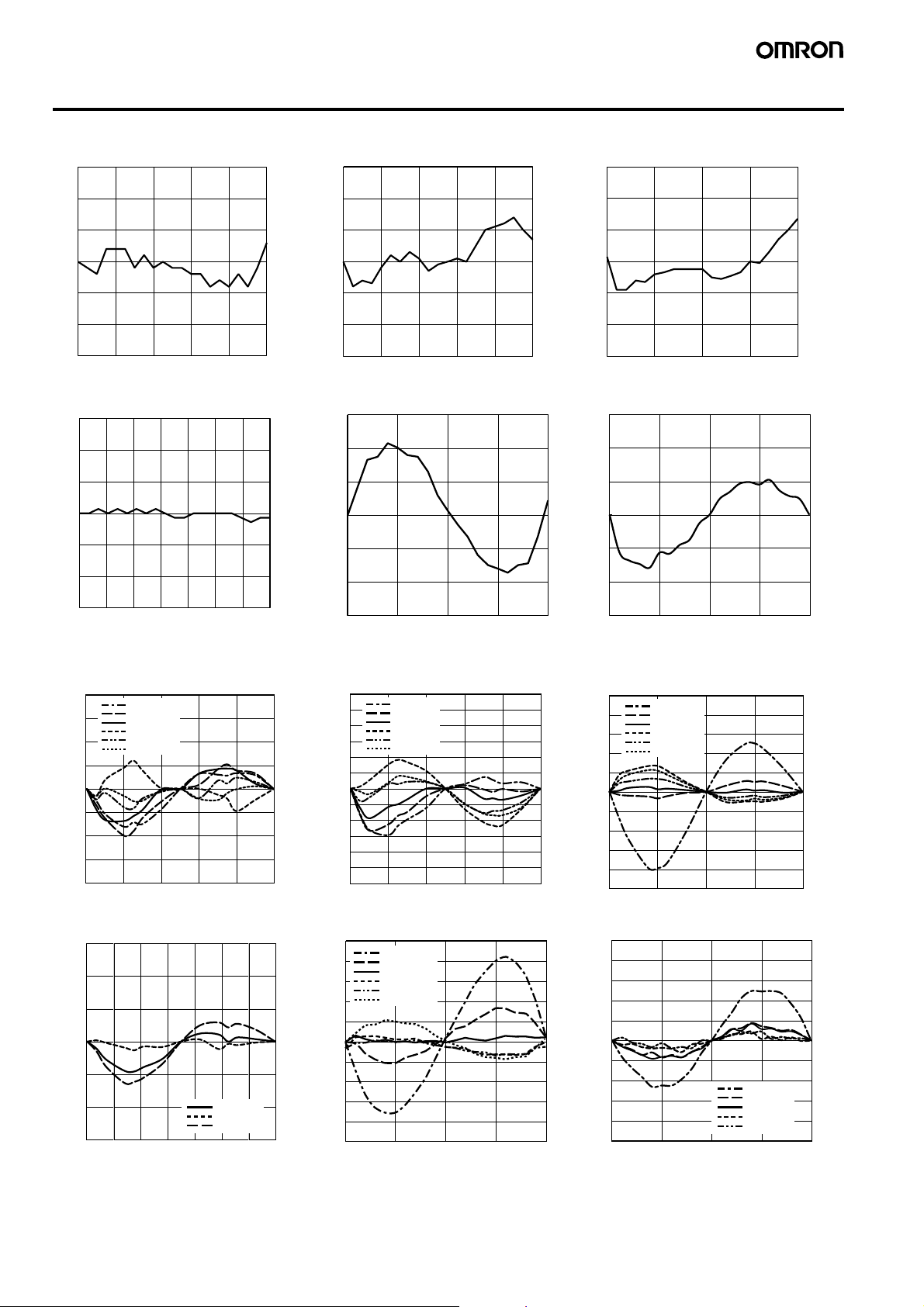
Engineering Data (Typical)
Measurement Distance vs. Linearity (with Linearity Adjusted for Standard Sensing Object)
ZX-EDR5T ZX-ED01T ZX-ED02T/ZX-EM02T
0.3
0.3
0.3
0.2
Linearity (% F.S.)
0.1
0
−0.1
−0.2
−0.3
0
0.1 0.2 0.3 0.4 0.5
Measurement distance (mm)
0.2
Linearity (% F.S.)
0.1
0
−0.1
−0.2
−0.3
0
0.2 0.4 0.6 0.8 1
Measurement distance (mm)
0.2
Linearity (% F.S.)
0.1
0
−0.1
−0.2
−0.3
0
0.5 1 1.5 2
ZX-EM07MT ZX-EV04T ZX-EM02HT
0.3
0.2
Linearity (% F.S.)
0.1
0
−0.1
−0.2
−0.3
1234 657
0
Measurement distance (mm)
0.3
0.2
Linearity (% F.S.)
0.1
0
−0.1
−0.2
−0.3
0.0
1.0 2.0 3.0 4.0
Measurement distance (mm)
0.3
0.2
Linearity (% F.S.)
0.1
0
−0.1
−0.2
−0.3
0
0.5 1 1.5 2
Size of Sensing Object vs. Linearity (with Linearity Adjusted for Each Sensing Object)
ZX-EDR5T ZX-ED01T ZX-ED02T/ZX-EM02T
0.4
0.3
0.2
Linearity (% F.S.)
0.1
0
−0.1
−0.2
−0.3
−0.4
0
S50C @5
S50C @8
S50C @12
S50C @18
S50C @30
S50C @45
0.1 0.2 0.3 0.4 0.5
Measurement distance (mm)
0.6
0.5
0.4
0.3
Linearity (% F.S.)
0.2
0.1
0
−0.1
−0.2
−0.3
−0.4
−0.5
−0.6
0
S50C @5
S50C @8
S50C @12
S50C @18
S50C @30
S50C @45
0.2 0.4 0.6 0.8 1
Measurement distance (mm)
1.0
0.8
0.6
Linearity (% F.S.)
0.4
0.2
0
−0.2
−0.4
−0.6
−0.8
−1.0
0
S50C @5
S50C @8
S50C @12
S50C @18
S50C @30
S50C @45
0.5 1 1.5 2
ZX-EM07MT ZX-EV04T ZX-EM02HT
0.3
0.2
Linearity (% F.S.)
0.1
0
−0.1
−0.2
−0.3
0
S50C @30
S50C @45
S50C @60
1234 567
Measurement distance (mm)
1
0.8
0.6
0.4
Linearity (% F.S.)
0.2
0
−0.2
−0.4
−0.6
−0.8
−1
0.0
S50C @8
S50C @12
S50C @18
S50C @30
S50C @45
S50C @60
1.0 2.0 3.0 4.0
Measurement distance (mm)
0.5
0.4
0.3
Linearity (% F.S.)
0.2
0.1
0
−0.1
−0.2
−0.3
−0.4
−0.5
0
0.5 1 1.5 2
Measurement distance (mm)
Measurement distance (mm)
Measurement distance (mm)
S50C @8
S50C @12
S50C @18
S50C @30
S50C @45
Measurement distance (mm)
4 ZX-E Series Smart Sensors (Inductive Displacement Type)
Page 5
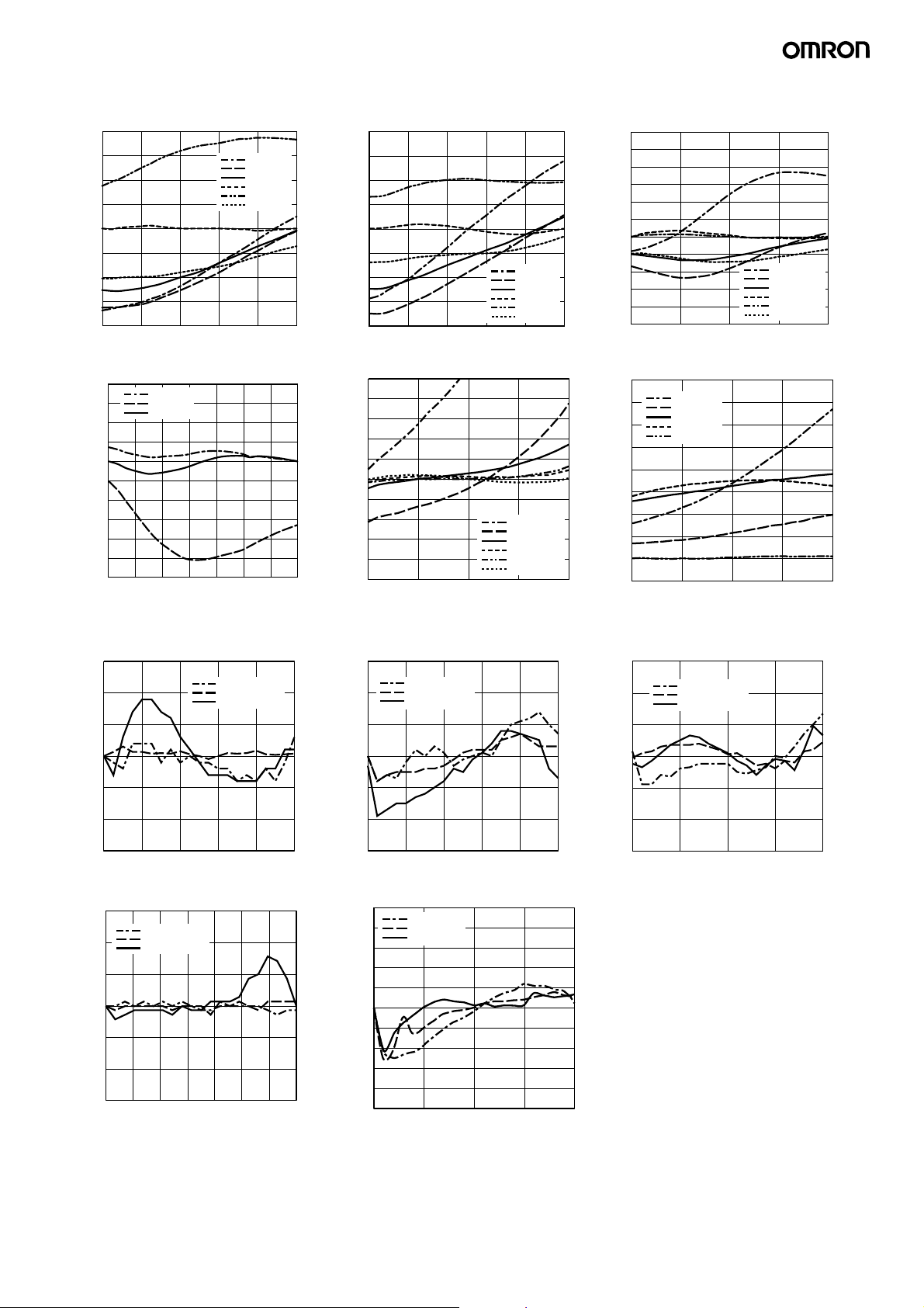
Size of Sensing Object vs. Linearity (with Linearity Adjusted for Standard Sensing Object)
ZX-EDR5T ZX-ED01T ZX-ED02T/ZX-EM02T
4
3
2
Linearity (% F.S.)
1
0
−1
−2
−3
−4
0.1 0.2 0.3 0.4 0.5
0
S50C @5
S50C @8
S50C @12
S50C @18
S50C @30
S50C @45
Measurement distance (mm)
4
3
2
Linearity (% F.S.)
1
0
−1
−2
−3
−4
0.2 0.4 0.6 0.8 1
0
S50C @5
S50C @8
S50C @12
S50C @18
S50C @30
S50C @45
Measurement distance (mm)
6
5
4
3
Linearity (% F.S.)
2
1
0
−1
−2
−3
−4
−5
0
0.5 1 1.5 2
ZX-EM07MT ZX-EV04T ZX-EM02HT
0.8
0.6
0.4
Linearity (% F.S.)
0.2
0
−0.2
−0.4
−0.6
−0.8
−1
−1.2
S50C @30
S50C @45
S50C @60
01234567
Measurement distance (mm)
Material of Sensing Object vs. Linearity (
5
4
3
2
Linearity (% F.S.)
1
0
−1
−2
−3
−4
−5
0.0
1.0 2.0 3.0 4.0
S50C @8
S50C @12
S50C @18
S50C @30
S50C @45
S50C @60
Measurement distance (mm)
with Linearity Adjusted for Each Sensing Object)
8
7
6
Linearity (% F.S.)
5
4
3
2
1
0
−1
0
S50C @8
S50C @12
S50C @18
S50C @30
S50C @45
0.5 1 1.5 2
ZX-EDR5T ZX-ED01T ZX-ED02T/ZX-EM02T
0.3
0.2
Linearity (% F.S.)
0.1
S50C @18
SUS304 @18
A5052 @18
0.3
0.2
Linearity (% F.S.)
0.1
S50C @18
SUS304 @18
A5052 @18
0.3
0.2
Linearity (% F.S.)
0.1
S50C @30
SUS304 @30
A5052 @30
S50C @5
S50C @8
S50C @12
S50C @18
S50C @30
S50C @45
Measurement distance (mm)
Measurement distance (mm)
−0.1
−0.2
−0.3
0
0.1 0.2 0.3 0.4 0.5
0
Measurement distance (mm)
−0.1
−0.2
−0.3
0
0
ZX-EM07MT ZX-EV04T
0.3
S50C @60
0.2
Linearity (% F.S.)
0.1
−0.1
−0.2
−0.3
SUS304 @60
A5052 @60
0
1234 657
0
Measurement distance (mm)
0.5
0.4
0.3
0.2
Linearity (% F.S.)
0.1
0
−0.1
−0.2
−0.3
−0.4
−5
0.0
ZX-E Series Smart Sensors (Inductive Displacement Type) 5
0.2 0.4 0.6 0.8 1
S50C @60
SUS304 @60
A5052 @60
Measurement distance (mm)
1.0 2.0 3.0 4.0
Measurement distance (mm)
−0.1
−0.2
−0.3
0
0.5 1 1.5 2
0
Measurement distance (mm)
Page 6
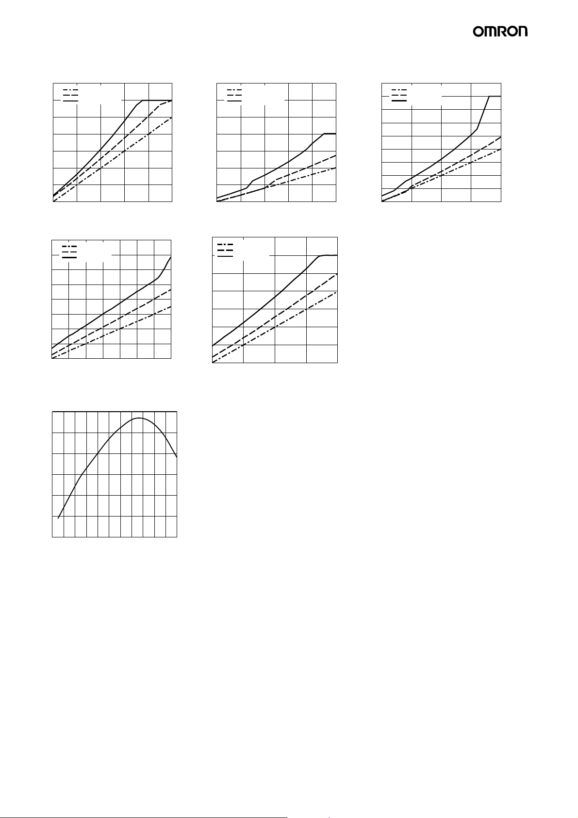
Material of Sensing Object vs. Linearity (with Linearity Adjusted for Standard Sensing Object and Iron)
ZX-EDR5T ZX-ED01T ZX-ED02T/ZX-EM02T
0.7
0.6
0.5
Display value (mm)
0.4
0.3
0.2
0.1
0
0.1 0.2 0.3 0.4 0.5
0
S50C @18
SUS304 @18
A5052 @18
Measurement distance (mm)
3.5
3
2.5
Display value (mm)
2
1.5
1
0.5
0
0.2 0.4 0.6 0.8 1
0
S50C @18
SUS304 @18
A5052 @18
Measurement distance (mm)
4.5
4
3.5
3
Display value (mm)
2.5
2
1.5
1
0.5
0
0
S50C @30
SUS304 @30
A5052 @30
0.5 1 1.5 2
ZX-EM07MT ZX-EV04T
16
14
12
Display value (mm)
10
8
6
4
2
0
S50C @60
SUS304 @60
A5052 @60
1234567
0
Measurement distance (mm)
7
S50C @60
SUS304 @60
6
A5052 @60
5
Display value (mm)
4
3
2
1
0
0.0
1.0 2.0 3.0 4.0
Measurement distance (mm)
Temperature Characteristics
ZX-EM02HT
1.0
Measurement distance (mm)
0.5
0
−0.5
−1
Rate of sensing distance change (%F.S.)
−1.5
−2
−20
200 40 60 80 180160140120100
Ambient sensor head temperature (°C)
200
6 ZX-E Series Smart Sensors (Inductive Displacement Type)
Page 7

I/O Circuit Diagrams
NPN Amplifier Unit: ZX-EDA11 PNP Amplifier Unit: ZX-EDA41
Brown: 12 to 24 VDC
Brown: 12 to 24 VDC
Load
Internal circuits
Current/voltage
switch
100 Ω
Current output
4 to 20 mA
Voltage output
±4V
White:
HIGH judgement output
Green:
PASS judgement output
Gray:
LOW judgement output
Blue: GND (0V)
Pink: Judgement output hold input
Purple: Timing input
Orange: Zero reset input
Red: Reset input
Black: Linear output
Shield: Linear GND
Load
Load
12 to 24 VDC
Current output: 300 Ω max.
Voltage output: 10 kΩ min.
Load
Connections: Amplifier Unit
Brown
12 to 24 VDC
Blue
GND (0V)
White
HIGH judgement output
Green
PASS judgement output
Gray
LOW judgement output
Black
Linear output
Shield
Linear output GND
Pink
Judgement output hold input
Orange
Zero reset input
Purple
Timing input
Red
Reset input
Note 1. Use a separate stabilized power supply for the Amplifier Unit,
particularly when high resolution is required.
2. Wire the Unit correctly. Incorrect wiring may result in damage
to the Unit. (Do not allow wiring, particularly the linear output,
to come into contact with other lines.)
3. Use the blue (0-V) line for the power supply and use the
shield wire (linear output ground) together with the black (linear output) line for linear output. Each of these grounds must
be used for the designed purpose. When not using the linear
output, connect the linear output ground to the 0-V ground.
Internal circuits
Current/voltage
switch
100 Ω
Current output
4 to 20 mA
Voltage output
±4V
White:
HIGH judgement output
Green:
PASS judgement output
Gray:
LOW judgement
output
Blue: GND (0V)
Pink: Judgement output hold input
Purple: Timing input
Orange: Zero reset input
Red: Reset input
Black: Linear output
Shield: Linear GND
Load
Load
Load
Current output:
300 Ω max.
Voltage output:
Load
10 kΩ min.
12 to
24 VDC
ZX-E Series Smart Sensors (Inductive Displacement Type) 7
Page 8

Part Names
Sensors
ZX-EDR5T
ZX-ED01T
ZX-ED02T
ZX-EM02T
ZX-EM07MT
ZX-EM02HT
Sensor head
ZX-EV04T
Sensor head
Preamplifier
Preamplifier
Output cable
(with connector)
Output cable
(with connector)
Amplifier Units
ZX-EDA11
ZX-EDA41
Controls
Display area
Input cable
(with connector)
Output cable
Connector
(Cover opens and closes)
Calculating Unit
ZX-CAL2
Display area
Connector
8 ZX-E Series Smart Sensors (Inductive Displacement Type)
Page 9

Precautions
■ Design Precautions
Conform to the specified ratings and performance. Refer to Specifications on page 2 for details.
Objects of certain materials or shapes may not be detectable, or the
detection accuracy may not be sufficiently high.
Environment
Do not operate the product in locations subject to flammable or explosive gases.
In order to ensure safe operation and maintenance, do not install the
product in the vicinity of high-voltage devices or power equipment.
■ Wiring
Do not use the product at voltages exceeding the rated values. Doing
so may result in damage.
Do not connect the product to an AC power supply or connect the
power supply in reverse.
Do not short-circuit the load for open-collector output.
■ Correct Use
Design Precautions
Power Supplies
Allow a warm-up period of approximately 30 minutes after turning ON
the power supply.
Mutual Interference
Up to 5 Sensor Heads can be used together by connecting the ZXCAL2 Calculating Unit between Amplifier Units.
When installing Sensor Heads facing each other or in parallel, separate them by the minimum distances given in the table below.
A
Mutual Interference
Model A B
ZX-EDR5T 5 mm 20 (3.1) mm
ZX-ED01T 10 mm 50 (5.4) mm
ZX-ED02T 20 mm 50 (8) mm
ZX-EM02T 20 mm 50 (10) mm
ZX-EM07MT 100 mm 150 (30) mm
ZX-EV04T 80 mm 50 (14) mm
ZX-EM02HT 20 mm 50 (12) mm
Note: The figures in parentheses apply when the mutual interfer-
ence prevention function is used.
Compatibility
Sensors and Amplifier Units are mutually compatible. Sensors can be
added or replaced individually.
Influence of High-frequency
Electromagnetic Fields
Using the product in the vicinity of devices that generate high-frequency electromagnetic fields, such as ultrasonic cleaning equipment, high-frequency generators, transceivers, mobile phones, and
inverters, may result in malfunction.
Calculating Unit
B
Do not lay the power cable for the product together with or in the same
duct as high-voltage lines or power lines. Doing so may result in incorrect operation or damage due to induction.
Do not connect or disconnect connectors while the power is ON. Doing so may result in damage.
■ Adjustment
Setting
When setting threshold values, ensure that the Amplifier Unit’s judgement output hold input line is ON so that there is no judgement output
to external devices.
■ Other Precautions
Do not attempt to disassemble, repair, or modify the product.
Dispose of the product using standard procedures for industrial
waste.
These Sensors are not compatible with the ZX-L@@ Smart Sensors
(laser type). Do not connect combinations of ZX-E@@ Smart Sensors
and ZX-T@@ Smart Sensors.
Influence of Metallic Objects
When installing the product, separate it from metallic objects by the
distances shown below.
d dia.
D
Influence of Metallic Objects
Model d D
ZX-EDR5T 8 mm 9 mm
ZX-ED01T 10 mm
ZX-ED02T/EM02T 12 mm
ZX-EM07MT 55 mm 20 mm
ZX-EV04T 16 × 32 mm 4.8 mm
ZX-EM02HT 18 mm 9 mm
Wiring
Wiring Check
After wiring is completed, before turning ON the power, confirm that
the power supply is connected correctly, that there are no faulty connections, such as load short-circuits, and that the load current is correct. Incorrect wiring may result in failure.
Cable Extension
Do not extend the cable for the Sensor and the Amplifier Unit to a
length exceeding 10 m. Use a ZX-XC@A Extension Cable (sold separately) to extend the Sensor’s cable. Extend the Amplifier Unit’s cable using a shielded cable of the same type.
Power Supply
When using a commercially available switching regulator, ground the
FG (frame ground) terminal.
If the power supply line is subject to surges, connect a surge absorber
that meets the conditions of the operating environment.
When using a Calculating Unit, connect the linear output ground of
the corresponding Amplifier Unit.
ZX-E Series Smart Sensors (Inductive Displacement Type) 9
Page 10

Connectors
Do not connect or disconnect connectors while the power is ON.
Be sure hold to connectors by the cover when connecting or disconnecting.
Mounting
Handling
When mounting the Sensor Head, do not apply excessive shock by,
for example, using a hammer. Doing so may result in damage or a reduction in the level of water-proofing. Also, there are screw-shaped
models that require a toothed washer to allow for a tolerance in the
tightening torque for the nut.
When using a heat-resistant model like the ZX-EM02HT, develop designs that account for thermal expansion due to rising sensing object
temperature so the sensing object will never touch the sensing surface. Also note that any sudden rise in temperature will shorten the
service life of the product.
Tightening Torque
Do not apply excessive torque when tightening the nut. Use a toothed
washer if necessary.
Model Tightening torque
ZX-EM02T 15 N·m
ZX-EM07MT
ZX-EM02HT 59 N·m
Note: The above figure applies for use with a toothed washer.
Mounting Cylindrical Models:
Tighten set screws with a tightening torque of 0.2 N·m max.
Set screw hole
A
Mounting Bracket
Y92E-F5R4 (for 5.4-dia.
screws), sold separately
Model A
ZX-EDR5T 9 to 18 mm
ZX-ED01T
ZX-ED02T 11 to 22 mm
Installation Location
Do not install the product in the following locations.
• Locations subject to temperatures outside the specified range
• Locations subject to condensation due to sudden temperature
changes
• Locations subject to humidity levels outside range 35% to 85%
• Locations subject to corrosive or flammable gases
• Locations subject to dust, salts, or metallic powder.
• Locations directly subject to vibrations and shocks
• Locations subject to direct sunlight
• Locations subject to splashes of water, oil, or chemicals
• Locations subject to strong electromagnetic or electrical fields
Maintenance and Inspection
• Be sure to turn OFF the power supply before adjusting or removing
the Sensor Head.
• Cleaning:
Do not use thinners, benzine, acetone, or kerosene for cleaning.
10 ZX-E Series Smart Sensors (Inductive Displacement Type)
Page 11

Dimensions
Sensors
Sensor Heads
ZX-EDR5T
(15.5)
3 dia.
Dimensions with Mounting Bracket Attached
Vinyl-insulated round cable
Vinyl-insulated coaxial round cable
18
1.7 dia., 1 conductor, standard length: 2 m
15 dia.
72
5.1 dia., 9 conductors, standard length: 200 mm
13
(46)
Connector
(15 dia.)
ZX-ED01T
ZX-ED02T
(15.5)
(15.5)
(22.5)
15
7.8
2715.6
58.2
15.1
Mounting Hole Cutout Dimensions
Two, M3 holes
0.1
27±
Dimensions with Mounting Bracket Attached
Vinyl-insulated round cable
Vinyl-insulated coaxial round cable
18
5.4 dia.
(22.5)
15
7.8
2.5 dia., 1 conductor, standard length: 2 m
15 dia.
72
2715.6
58.2
5.1 dia., 9 conductors, standard length: 200 mm
13
(46)
Connectors
(15 dia.)
15.1
Mounting Hole Cutout Dimensions
Two, M3 holes
0.1
27±
Dimensions with Mounting Bracket Attached
Vinyl-insulated round cable
5.1 dia., 9 conductors, standard length: 200 mm
13
(46)
Connector
(15 dia.)
8 dia.
Vinyl-insulated coaxial round cable
22
2.5 dia., 1 conductor, standard length: 2 m
15 dia.
72
(22.5)
15
7.8
2715.6
58.2
15.1
Mounting Hole Cutout Dimensions
Two, M3 holes
0.1
27±
ZX-E Series Smart Sensors (Inductive Displacement Type) 11
Page 12

ZX-EM02T
18 dia.
16
(5.4)
8 dia.
22
16.6
Dimensions with Mounting Bracket Attached
Vinyl-insulated round cable
Vinyl-insulated coaxial round cable
2.5 dia., 1 conductor, standard length: 2 m
5.1 dia., 9 conductors, standard length: 200 mm
13
(46)
(15 dia.)
ZX-EM07MT
29 dia.
24
(15.5)
10
15.7 dia.
(15.5)
4
(22.5)
15
7.8
M10×1
2 tightening nuts
2 toothed washers
15 dia.
72
2715.6
58.2
Connector
15.1
Mounting Hole Cutout Dimensions
Two, M3 holes
0.1
27±
Dimensions with Mounting Bracket Attached
46.3
25
4
(11.3)
9.8 dia.
M18×1
2 tightening nuts
2 toothed washers
Vinyl-insulated coaxial round cable
2.5 dia., 1 conductor, standard length: 2 m
15 dia.
72
Vinyl-insulated round cable
5.1 dia., 9 conductors, standard length: 200 mm
13
(46)
(15 dia.)
Connector
(22.5)
15
7.8
ZX-EV04T
14
(15.5)
(22.5)
15
7.8
Mounting Hole Cutout Dimensions
10±
7
4.8
Two, M3 holes
0.1
7
10
Sensing surface
10
30
2715.6
58.2
Mounting Hole Cutout Dimensions
Two, M3 holes
27±
Dimensions with Mounting Bracket Attached
Vinyl-insulated coaxial round cable
2.5 dia., 1 conductor, standard length: 2 m
Distance: 3 mm
Hole size: 3.3 dia. (2 holes)
15 dia.
1.5
72
2715.6
58.2
Mounting Hole Cutout Dimensions
Two, M3 holes
0.1
27±
15.1
0.1
13
(46)
(15 dia.)
15.1
Vinyl-insulated round cable
5.1 dia., 9 conductors,
standard length: 200 mm
Connector
12 ZX-E Series Smart Sensors (Inductive Displacement Type)
Page 13

ZX-EM02HT
21 dia.
17
(15.5)
(22.5)
15
7.8
Mounting Hole Cutout Dimensions
Two, M3 holes
Amplifier Units
ZX-EDA1 1
ZX-EDA4 1
27±
Dimensions with Mounting Bracket Attached
Fluororesin-insulated coaxial round cable
2.5 dia., single conductor
15 dia.
standard length: 2m
72
2715.6
58.2
13
Vinyl-insulated round cable
5.1 dia., 9 conductors,
standard length: 200 mm
(46)
15.1
Connector
22
0.1
10.5 dia.
M12×1
Two fastening nuts
Toothed washer
30
15.5 dia.
13.2
44
133
Vinyl-insulated round cable
5.1 dia., standard: 100 mm
3
13 36.8
11.7
64.3
2.2
29
Current/voltage switch
(Factory-set to voltage output.)
4.24.2
31.5
15.8
Vinyl-insulated round cable
5.2 dia., 10 conductors
(conductor cross-section: 0.09 mm
insulator diameter: 0.7 mm),
standard length: 2 m
11.7
Voltage output
2
,
ZX-E Series Smart Sensors (Inductive Displacement Type) 13
Page 14

Accessories (Sold Separately)
Preamplifier Mounting Bracket
ZX-XBE1 ZX-XBE2
0.1
27±
15.5
63.3
21.9
52
20
9.8
15.5
21.9
0.1
27±
15.5
M3×8 pan-head screw (with M3 spring washer)
63.3
52
20
9.8
6.2 10
31.9
15.5
Material: Stainless steel (SUS304)
Calculating Unit
ZX-CAL2
15.1
12
8
30
26
14.4
9.4
11.4
Operation
24.9
3
19.5
5
3.4
indicators
57
54.9
44.05
9.5
36.7
Connectors
15
1.8
35.3
58
Material: Stainless steel (SUS304)
1.8
10
14 ZX-E Series Smart Sensors (Inductive Displacement Type)
Page 15

ZX-series Communications Interface Unit
ZX-SF11
Sensor communications indicator (communications operation)
Sensor communications indicator (communications error)
Connector
30
(46)
15
13.2
(33.1)
Connector
(336)
Vinyl-insulation round cable, 5.23 dia.
Cables with Connectors on Both Ends (for Extension)
ZX-XC1A (1 m)
ZX-XC4A (4 m)
ZX-XC8A (8 m)
46
Power supply indicator
4.2
3
29
11.7
External terminal communications
indicator (communications operation)
External terminal communications
indicator (communications error)
64.3 4.2
36.813
2.2
44
31.5
4.3
11.7
6.5553
15 dia.
Vinyl-insulated round cable, 5.2 dia., 10 conductors
*ZX-XC1A: 1,000
ZX-XC4A: 4,000
ZX-XC8A: 8,000
15.5 dia.
12 pins (female)12 pins (male)
ZX-E Series Smart Sensors (Inductive Displacement Type) 15
Page 16

.
ALL DIMENSIONS SHOWN ARE IN MILLIMETERS.
To convert millimeters into inches, multiply by 0.03937. To convert grams into ounces, multiply by 0.03527.
This document provides information mainly for selecting suitable models. Please read the manual carefully for
information that the user must understand and accept before purchase, including information on warranty,
limitations of liability, and precautions.
CSM_2_1_0609
E331-E1
In the interest of product improvement, specifications are subject to change without notice
OMRON Corporation
Industrial Automation Company
Sensing Devices Division H.Q.
Application Sensors Division
Shiokoji Horikawa, Shimogyo-ku,
Kyoto, 600-8530 Japan
Tel: (81)75-344-7068/Fax: (81)75-344-7107
Page 17

Read and Understand This Catalog
Please read and understand this catalog before purchasing the products. Please consult your OMRON representative if you have any questions or
comments.
Warranty and Limitations of Liability
WARRANTY
OMRON's exclusive warranty is that the products are free from defects in materials and workmanship for a period of one year (or other period if specified)
from date of sale by OMRON.
OMRON MAKES NO WARRANTY OR REPRESENTATION, EXPRESS OR IMPLIED, REGARDING NON-INFRINGEMENT, MERCHANTABILITY, OR
FITNESS FOR PARTICULAR PURPOSE OF THE PRODUCTS. ANY BUYER OR USER ACKNOWLEDGES THAT THE BUYER OR USER ALONE HAS
DETERMINED THAT THE PRODUCTS WILL SUITABLY MEET THE REQUIREMENTS OF THEIR INTENDED USE. OMRON DISCLAIMS ALL OTHER
WARRANTIES, EXPRESS OR IMPLIED.
LIMITATIONS OF LIABILITY
OMRON SHALL NOT BE RESPONSIBLE FOR SPECIAL, INDIRECT, OR CONSEQUENTIAL DAMAGES, LOSS OF PROFITS OR COMMERCIAL LOSS
IN ANY WAY CONNECTED WITH THE PRODUCTS, WHETHER SUCH CLAIM IS BASED ON CONTRACT, WARRANTY, NEGLIGENCE, OR STRICT
LIABILITY.
In no event shall the responsibility of OMRON for any act exceed the individual price of the product on which liability is asserted.
IN NO EVENT SHALL OMRON BE RESPONSIBLE FOR WARRANTY, REPAIR, OR OTHER CLAIMS REGARDING THE PRODUCTS UNLESS
OMRON'S ANALYSIS CONFIRMS THAT THE PRODUCTS WERE PROPERLY HANDLED, STORED, INSTALLED, AND MAINTAINED AND NOT
SUBJECT TO CONTAMINATION, ABUSE, MISUSE, OR INAPPROPRIATE MODIFICATION OR REPAIR.
Application Considerations
SUITABILITY FOR USE
OMRON shall not be responsible for conformity with any standards, codes, or regulations that apply to the combination of products in the customer's
application or use of the products.
At the customer's request, OMRON will provide applicable third party certification documents identifying ratings and limitations of use that apply to the
products. This information by itself is not sufficient for a complete determination of the suitability of the products in combination with the end product,
machine, system, or other application or use.
The following are some examples of applications for which particular attention must be given. This is not intended to be an exhaustive list of all possible
uses of the products, nor is it intended to imply that the uses listed may be suitable for the products:
•
Outdoor use, uses involving potential chemical contamination or electrical interference, or conditions or uses not described in this catalog.
•
Nuclear energy control systems, combustion systems, railroad systems, aviation systems, medical equipment, amusement machines, vehicles,
safety equipment, and installations subject to separate industry or government regulations.
•
Systems, machines, and equipment that could present a risk to life or property.
Please know and observe all prohibitions of use applicable to the products.
NEVER USE THE PRODUCTS FOR AN APPLICATION INVOLVING SERIOUS RISK TO LIFE OR PROPERTY WITHOUT ENSURING THAT THE
SYSTEM AS A WHOLE HAS BEEN DESIGNED TO ADDRESS THE RISKS, AND THAT THE OMRON PRODUCTS ARE PROPERLY RATED AND
INSTALLED FOR THE INTENDED USE WITHIN THE OVERALL EQUIPMENT OR SYSTEM.
PROGRAMMABLE PRODUCTS
OMRON shall not be responsible for the user's programming of a programmable product, or any consequence thereof.
Disclaimers
CHANGE IN SPECIFICATIONS
Product specifications and accessories may be changed at any time based on improvements and other reasons.
It is our practice to change model numbers when published ratings or features are changed, or when significant construction changes are made.
However, some specifications of the products may be changed without any notice. When in doubt, special model numbers may be assigned to fix or
establish key specifications for your application on your request. Please consult with your OMRON representative at any time to confirm actual
specifications of purchased products.
DIMENSIONS AND WEIGHTS
Dimensions and weights are nominal and are not to be used for manufacturing purposes, even when tolerances are shown.
PERFORMANCE DATA
Performance data given in this catalog is provided as a guide for the user in determining suitability and does not constitute a warranty. It may represent the
result of OMRON’s test conditions, and the users must correlate it to actual application requirements. Actual performance is subject to the OMRON
Warranty and Limitations of Liability.
ERRORS AND OMISSIONS
The information in this document has been carefully checked and is believed to be accurate; however, no responsibility is assumed for clerical,
typographical, or proofreading errors, or omissions.
In the interest of product improvement, specifications are subject to change without notice.
OMRON Corporation
Industrial Automation Company
http://www.ia.omron.com/
(c)Copyright OMRON Corporation 2009 All Right Reserved.
2009.6
 Loading...