

Page 1

PRECISION 4.096 VOLT LOW KNEE CURRENT
VOLTAGE REFERENCE
ISSUE 3 - MARCH 1998
ZRC400
DEVICE DESCRIPTION
The ZRC400 uses a bandgap circuit design to
achieve a precision micropower voltage
reference of 4.096 volts. The device is
available in small outline surface mount
packages, ideal for applications where space
saving is important, as well as packages for
through hole requirements.
The ZRC400 design provides a stable voltage
without an external capacitor and is stable
with capacitive loads. The ZRC400 is
recommended for operation between 23µA
and 5mA and so is ideally suited to low
power and battery powered applications.
Excellent performance is maintained to an
absolute maximum of 25mA, however the
rugged design and 20 volt processing allows
the reference to withstand transient effects
and currents up to 200mA. Superior
switching capability allows the device to
reach stable operating conditions in only a
few microseconds.
SCHEMATIC DIAGRAM
FEATURES
Small outline SOT23 , SO8 and TO92
•
style packages
No stabilising capacitor required
•
Low knee current, 18µA typical
•
Typical TC 30ppm/°C
•
Typical slope resistance 0.4Ω
•
± 3%, 2% and 1% tolerance
•
Industrial temperature range
•
Operating current 23µA to 5mA
•
Transient response, stable in less than
•
10µs
Optional extended current range
•
APPLICATIONS
Battery powered and portable
•
equipment.
Instrumentation.
•
Test equipment.
•
Metering and measurement systems.
•
V
G
R
nd
4-257
Page 2

ZRC400
ABSOLUTE MAXIMUM RATING
Reverse Current 25mA
Forward Current 25mA
Operating Temperature -40 to 85°C
Storage Temperature -55 to 125°C
ELECTRICAL CHARACTERISTICS
TEST CONDITIONS (Unless otherwise stated) T
Power Dissipation (T
SOT23 330mW
E-Line, 3 pin (TO92) 500mW
E-Line, 2 pin (TO92) 500mW
SO8 625mW
amb
=25°C
amb
=25°C)
SYMBOL PARAMETER
CONDITIONS LIMITS TOL.%UNITS
MIN TYP MAX
V
I
I
R
MIN
R
Reverse Breakdown Voltage
=150µA
I
R
Minimum Operating Current 18 23
Recommended Operating
4.055
4.096
4.014
4.096
3.973
4.096
0.023 5 mA
Current
T
† Average Reverse Breakdown
C
R
S
Z
R
Voltage Temp. Co. I
§ Slope Resistance 0.4 2
R(min)
I
R(max)
to
Reverse Dynamic Impedance IR =1mA
30 90 ppm/°C
0.3 0.8
f = 100Hz
I
=0.1 I
AC
R
E
N
Wideband Noise Voltage
=150µA
I
R
90
f=10Hz to
10kHz
(
V
−
V
†
T
Note: V
=
C
R(max)
R(max
V
- V
)
x (
R
R(min)
) x 1000000
R(min
)
T
−
T
(
max
)
)
(
min
)
is the maximum
deviation in reference voltage measured
over the full operating temperature
40
30
20
range.
§
V
Change
(
I
to
I
R
R
=
S
I
R (max
R
(
min
)
I
−
)
R (min
R (max
)
)
)
Reverse Current (uA)
10
0
Reverse Characteristics
4.137
1
4.178
2
4.219
3
25 °C
85 °C
Reverse Voltage (V)
V
µA
Ω
Ω
µV(rms)
-40 °C
501234
4-258
Page 3
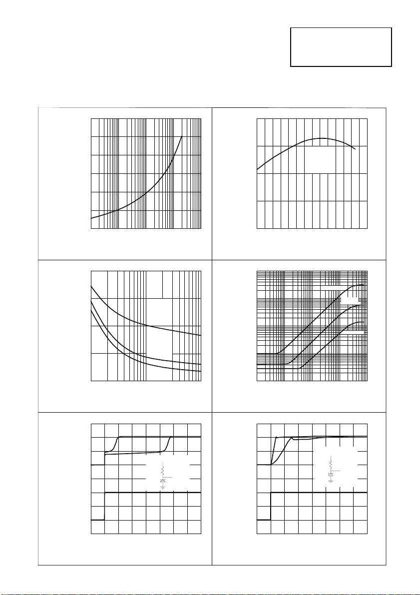
TYPICAL CHARACTERISTICS
ZRC400
1.6
1.4
1.2
1.0
0.8
Forward Voltage (V)
0.6
0.4
0.1 1 10 100 1000
Forward Current (mA)
Forward Characteristics
2
1.5
1
0.5
Slope Resistance (Ohms)
0
0.1
Ta=-40°C
Ta=25°C
Ta= 8 5 °C
110
Reference Current (mA)
Slope Resistance vs. Current
4.10
Iref=100µA
4.09
Reference Voltage (V)
4.08
-20 0 20 40
Temperature (°C)
Temperature Drift
1000
Iref=150µA
100
10
1
Slope Resistance (Ohms)
0.1
10
100 1K 10K 100K
Frequency (Hz)
Slope Resistance vs. Frequency
60 80 100-40
Iref=1mA
Iref=5mA
5mA
150µA
0
200 400 600
1K2
5mA
VIN
39K
150µA
Vout (V)
Vin (V)
4
2
0
10
0
Time (µs)
Transient Response (Single Pulse)
5mA
150µA
206
Vout (V)
Vin (V)
4
2
0
10
0
Tim e (µs )
Transient Response (Repetitive Pulse)
4-259
1K2
5mA
VIN
39K
150µA
4
Page 4
ZRC400
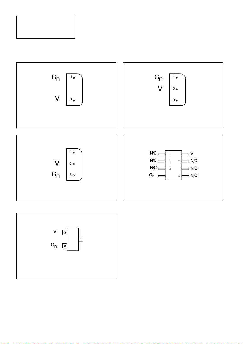
CONNECTION DIAGRAMS
E-Line, 2 pin Package Suffix – Y
Bottom View
E-Line, 3 pin Package Suffix – A
Bottom View –
Pin 1 floating or connected to pin 3
SOT23 Package Suffix – F
E-Line, 3 pin,Rev Package Suffix – R
Bottom View –
Pin 3 floating or connected to pin 1
SO8 Package Suffix – N8
Top View
Top View –
Pin 1 floating or connected to pin 2
4-260
Page 5
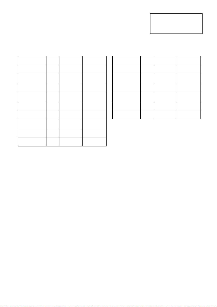
ORDERING INFORMATION
ZRC400
Part No Tol% Package Partmark
ZRC400A03 3 E-Line • ZRC40003
ZRC400A02 2 E-Line • ZRC40002
ZRC400A01 1 E-Line • ZRC40001
ZRC400F03 3 SOT23 40D
ZRC400F02 2 SOT23 40G
ZRC400F01 1 SOT23 40H
ZRC400N803 3 SO8 ZRC40003
ZRC400N802 2 SO8 ZRC40002
ZRC400N801 1 SO8 ZRC40001
Part No Tol% Package Partmark
ZRC400R03 3 E-Line * ZRC400R3
ZRC400R02 2 E-Line * ZRC400R2
ZRC400R01 1 E-Line * ZRC400R1
ZRC400Y03 3 E-Line † ZRC40003
ZRC400Y02 2 E-Line † ZRC40002
ZRC400Y01 1 E-Line † ZRC40001
* E-Line 3 pin Reversed
† E-Line 2 pin
• E-Line 3 pin
4-261
 Loading...