

Page 1
FEATURES
♦ Silicon Planar Power Zener Diodes
♦ For use in stabilizing and clipping circuits with higher
power rating.
♦ The Zener voltages are graded according to the
international E24 standard. Smaller voltage tolerances
and other Zener voltages are available upon request.
♦ These diodes are also available in the DO-41 case with the type
designation ZPY1 … ZPY100.
MECHANICAL DATA
Case: MELF Glass Case
Weight: approx. 0.25 g
MAXIMUM RATINGS
Ratings at 25°C ambient temperature unless otherwise specified.
SYMBOL VALUE UNIT
Zener Current (see Table “Characteristics”)
Power Dissipation at T
amb
= 25°C P
tot
1.0
1)
W
Junction Temperature T
j
150 °C
Storage Temperature Range T
S
– 55 to +150 °C
ZMY1 THRU ZMY100
ZENER DIODES
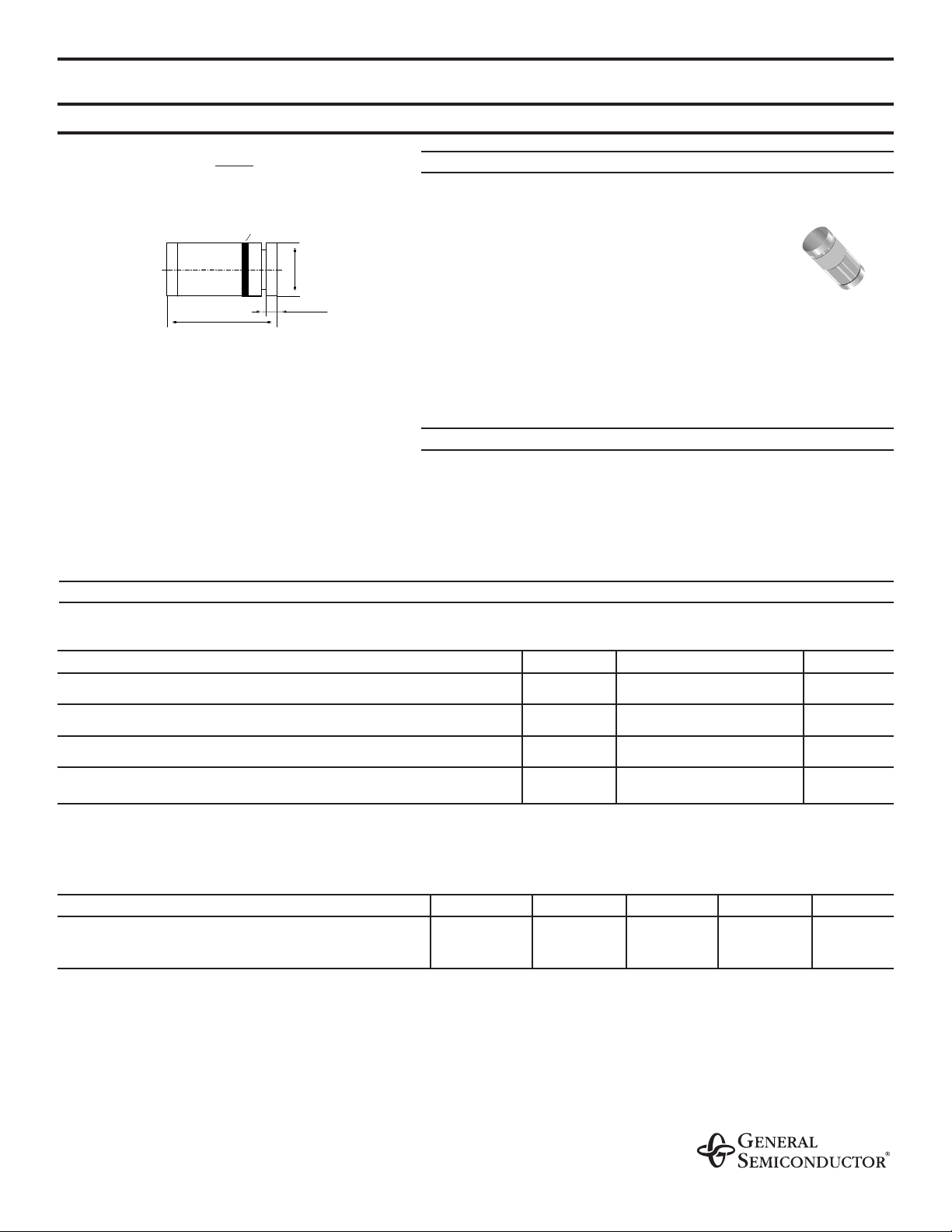
.022 (0.55)
.205 (5.2)
.102 (2.6)
Cathode Mark
.189 (4.8)
.094 (2.4)
MELF
Dimensions are in inches and (millimeters)
Characteristics at Tamb = 25 °C
SYMBOL MIN. TYP. MAX. UNIT
Thermal Resistance
R
thJA
– – 170
1)
°C/W
Junction to Ambient Air
NOTES:
(1) Valid provided that electrodes are kept at ambient temperature.
12/16/98
Page 2

ZMY1 THRU ZMY100
ELECTRICAL CHARACTERISTICS
Ratings at 25°C ambient temperature unless otherwise specified.
Type
Zener
voltage
(2)
at
I
ZT
min. max.
VZ(V)
Dynamic
resistance
at I
ZT
f = 1 kHz
max
rzj(Ω)
Temp. coeff.
of Zener volt.
at
I
ZT
α
VZ
(10–4/K)
Test
current
I
ZT
(mA)
Reverse
voltage
at
IR= 0.5µA
VR(V)
Admissible
Zener current
(1)
at T
amb
= 25°C
IZ(mA)
ZMY1
(3)
0.65 … 0.75 6.5 (< 8) –26 … –23 5 – 406
ZMY3.9 3.7 … 4.1 4 (< 7) –7 … +2 100 – 203
ZMY4.3 4.0 … 4.6 4 (< 7) –7 … +3 100 – 182
ZMY4.7 4.4 … 5.0 4 (< 7) –7 … +4 100 – 165
ZMY5.1 4.8 … 5.4 2 (< 5) –6 … +5 100 > 0.7 150
ZMY5.6 5.2 … 6.0 1 (< 2) –3 … +5 100 > 1.5 135
ZMY6.2 5.8 … 6.6 1 (< 2) –1 … +6 100 > 2.0 128
ZMY6.8 6.4 … 7.2 1 (< 2) 0 … +7 100 > 3.0 110
ZMY7.5 7.0 … 7.9 1 (< 2) 0 … +7 100 > 5.0 100
ZMY8.2 7.7 … 8.7 1 (< 2) +3 … +8 100 > 6.0 89
ZMY9.1 8.5 … 9.6 2 (< 4) +3 … +8 50 > 7.0 82
ZMY10 9.4 … 10.6 2 (< 4) +5 … +9 50 > 7.5 74
ZMY11 10.4 … 11.6 3 (< 7) +5 … +10 50 > 8.5 66
ZMY12 11.4 … 12.7 3 (< 7) +5 … +10 50 > 9.0 60
ZMY13 12.4 … 14.1 4 (< 9) +5 … +10 50 > 10 55
ZMY15 13.8 … 15.8 4 (< 9) +5 … +10 50 > 11 49
ZMY16 15.3 … 17.1 5 (< 10) +7 … +11 25 > 12 44
ZMY18 16.8 … 19.1 5 (< 11) +7 … +11 25 > 14 40
ZMY20 18.8 … 21.2 6 (< 12) +7 … +11 25 > 15 36
ZMY22 20.8 … 23.3 7 (< 13) +7 … +11 25 > 17 34
ZMY24 22.8 … 25.6 8 (< 14) +7 … +12 25 > 18 29
ZMY27 25.1 … 28.9 9 (< 15) +7 … +12 25 > 20 27
ZMY30 28 … 32 10 (< 20) +7 … +12 25 > 22.5 25
ZMY33 31 … 35 11 (< 20) +7 … +12 25 > 25 22
ZMY36 34 … 38 25 (< 60) +7 … +12 10 > 27 20
ZMY39 37 … 41 30 (< 60) +8 … +12 10 > 29 18
ZMY43 40 … 46 35 (< 80) +8 … +13 10 > 32 17
ZMY47 44 … 50 40 (< 80) +8 … +13 10 > 35 15
ZMY51 48 … 54 45 (< 100) +8 … +13 10 > 38 14
ZMY56 52 … 60 50 (< 100) +8 … +13 10 > 42 13
ZMY62 58 … 66 60 (< 130) +8 … +13 10 > 47 11
ZMY68 64 … 72 65 (< 130) +8 … +13 10 > 51 10
ZMY75 70 … 79 70 (< 160) +8 … +13 10 > 56 9
ZMY82 77 … 88 80 (< 160) +8 … +13 10 > 61 8
ZMY91 85 … 96 120 (< 250) +9 … +13 5 > 68 7.5
ZMY100 94 … 106 130 (< 250) +9 … +13 5 > 75 7
NOTES:
(1) Valid provided that electrodes are kept at ambient temperature
(2) Tested with pulses t
p
= 5 ms
(3) The ZMY1 is a silicon diode operated in forward direction. Hence, the index of all characteristics and maximum ratings should be “F” instead of “Z”.
Connect the cathode terminal to the negative pole
For devices in glass case MELF with higher Zener voltage but same power dissipation see types ZMU100 … ZMU180
Page 3
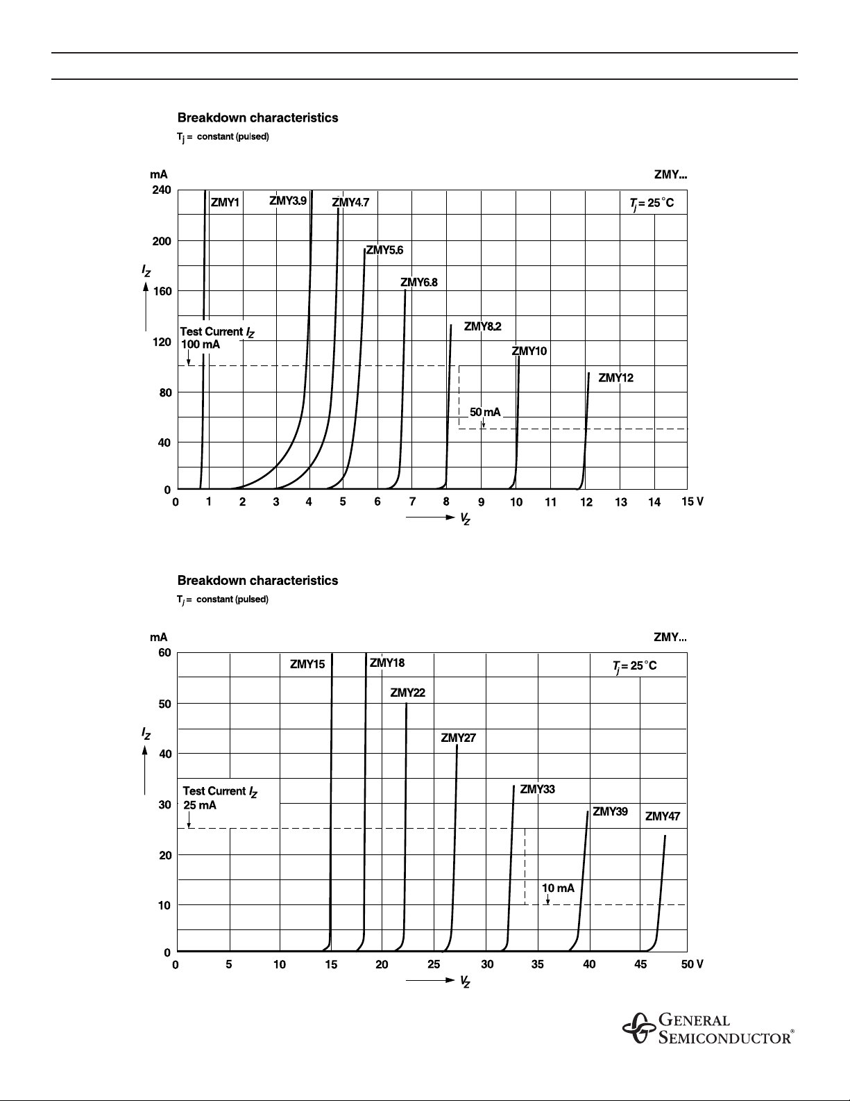
RATINGS AND CHARACTERISTIC CURVES ZMY1 THRU ZMY100
Page 4
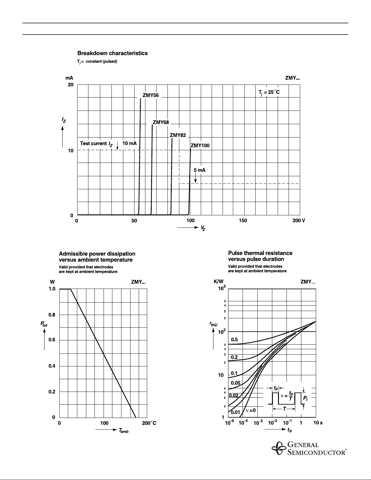
RATINGS AND CHARACTERISTIC CURVES ZMY1 THRU ZMY100
Page 5
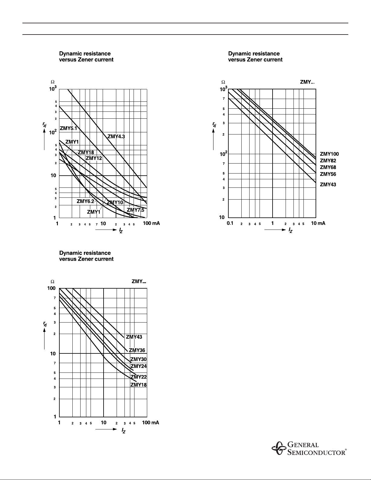
RATINGS AND CHARACTERISTIC CURVES ZMY1 THRU ZMY100
 Loading...