

Page 1

Cat. No. Z251-E1-01
Smart Sensor
ZFX-C10/C15
Vision Sensor with
built-in LCD monitor
USERS MANUAL
Page 2
APPLICATION CONSIDERATIONS
(Please Read)
1
User's Manual
BEFORE USE
BASIC OPERATIONS
SETTING THE MEASUREMENT
CONDITIONS
FUNCTIONS USED DURING OPERATION
ADDITIONAL FUNCTIONS
PARALLEL INTERFACE
1
2
3
4
5
6
Smart Sensor
Vision Sensor with built-in LCD monitor
ZFX-C10
APPENDICES
7
Page 3

READ AND UNDERSTAND THIS DOCUMENT
Please read and understand this document before using the products. Please consult your OMRON
representative if you have any questions or comments.
WARRANTY
OMRON’s exclusive warranty is that the products are free from defects in materials and workmanship for a
period of one year (or other period if specified) from date of sale by OMRON.
OMRON MAKES NO WARRANTY OR REPRESENTATION, EXPRESS OR IMPLIED, REGARDING NONINFRINGEMENT, MERCHANTABILITY, OR FITNESS FOR PARTICULAR PURPOSE OF THE PRODUCTS.
ANY BUYER OR USER ACKNOWLEDGES THAT THE BUYER OR USER ALONE HAS DETERMINED THAT
THE PRODUCTS WILL SUITABLY MEET THE REQUIREMENTS OF THEIR INTENDED USE. OMRON
DISCLAIMS ALL OTHER WARRANTIES, EXPRESS OR IMPLIED.
LIMITATIONS OF LIABILITY
OMRON SHALL NOT BE RESPONSIBLE FOR SPECIAL, INDIRECT, OR CONSEQUENTIAL DAMAGES,
LOSS OF PROFITS OR COMMERCIAL LOSS IN ANY WAY CONNECTED WITH THE PRODUCTS,
WHETHER SUCH CLAIM IS BASED ON CONTRACT, WARRANTY, NEGLIGENCE, OR STRICT LIABILITY.
In no event shall responsibility of OMRON for any act exceed the individual price of the product on which
liability is asserted.
IN NO EVENT SHALL OMRON BE RESPONSIBLE FOR WARRANTY, REPAIR, OR OTHER CLAIMS
REGARDING THE PRODUCTS UNLESS OMRON’S ANALYSIS CONFIRMS THAT THE PRODUCTS WERE
PROPERLY HANDLED, STORED, INSTALLED, AND MAINTAINED AND NOT SUBJECT TO
CONTAMINATION, ABUSE, MISUSE, OR INAPPROPRIATE MODIFICATION OR REPAIR.
SUITABILITY FOR USE
THE PRODUCTS CONTAINED IN THIS DOCUMENT ARE NOT SAFETY RATED. THEY ARE NOT DESIGNED OR
RATED FOR ENSURING SAFETY OF PERSONS, AND SHOULD NOT BE RELIED UPON AS A SAFETY COMPONENT OR PROTECTIVE DEVICE FOR SUCH PURPOSES.
Please refer to separate catalogs for OMRON’s safety rated products.
OMRON shall not be responsible for conformity with any standards, codes, or regulations that apply to the
combination of products in the customer’s application or use of the product.
At the customer’s request, OMRON will provide applicable third party certification documents identifying ratings
and limitations of use that apply to the products. This information by itself is not sufficient for a complete
determination of the suitability of the products in combination with the end product, machine, system, or other
application or use.
The following are some examples of applications for which particular attention must be given. This is not
intended to be an exhaustive list of all possible uses of the products, nor is it intended to imply that the uses
listed may be suitable for the products:
• Outdoor use, uses involving potential chemical contamination or electrical interference, or conditions or
uses not described in this document.
2
ZFX-C User’s Manual
Page 4

• Nuclear energy control systems, combustion systems, railroad systems, aviation systems, medical
equipment, amusement machines, vehicles, safety equipment, and installations subject to separate industry
or government regulations.
• Systems, machines, and equipment that could present a risk to life or property.
Please know and observe all prohibitions of use applicable to the products.
NEVER USE THE PRODUCTS FOR AN APPLICATION INVOLVING SERIOUS RISK TO LIFE OR
PROPERTY WITHOUT ENSURING THAT THE SYSTEM AS A WHOLE HAS BEEN DESIGNED TO
ADDRESS THE RISKS, AND THAT THE OMRON PRODUCT IS PROPERLY RATED AND INSTALLED FOR
THE INTENDED USE WITHIN THE OVERALL EQUIPMENT OR SYSTEM.
PERFORMANCE DATA
Performance data given in this document is provided as a guide for the user in determining suitability and does
not constitute a warranty. It may represent the result of OMRON’s test conditions, and the users must correlate
it to actual application requirements. Actual performance is subject to the OMRON Warranty and Limitations of
Liability.
CHANGE IN SPECIFICATIONS
Product specifications and accessories may be changed at any time based on improvements and other
reasons.
It is our practice to change model numbers when published ratings or features are changed, or when significant
construction changes are made. However, some specifications of the product may be changed without any
notice. When in doubt, special model numbers may be assigned to fix or establish key specifications for your
application on your request. Please consult with your OMRON representative at any time to confirm actual
specifications of purchased products.
DIMENSIONS AND WEIGHTS
Dimensions and weights are nominal and are not to be used for manufacturing purposes, even when
tolerances are shown.
ERRORS AND OMISSIONS
The information in this document has been carefully checked and is believed to be accurate; however, no
responsibility is assumed for clerical, typographical, or proofreading errors, or omissions.
PROGRAMMABLE PRODUCTS
OMRON shall not be responsible for the user’s programming of a programmable product, or any consequence
thereof.
COPYRIGHT AND COPY PERMISSION
This document shall not be copied for sales or promotions without permission.
This document is protected by copyright and is intended solely for use in conjunction with the product. Please
notify us before copying or reproducing this document in any manner, for any other purpose. If copying or
transmitting this document to another, please copy or transmit it in its entirety.
ZFX-C User’s Manual
3
Page 5
Meanings of Signal Words
The following signal words are used in this manual.
Indicates a potentially hazardous situation which, if not avoided, will result in minor or
moderate injury, or may result in serious injury or death. Additionally there may be
significant property damage.
Meanings of Alert Symbols
The following alert symbols are used in this manual
Indicates general prohibitions for which there is no specific symbol.
Indicates the possibility of laser radiation.
Indicates the possibility of explosion under specific conditions.
This product is not designed or rated for ensuring safety of persons.
Do not use it for such purposes.
The camera with lighting emits visible light, which may adversely affect the eyes in rare instances.
Do not look directly into the light emitted from the Camera. When the subject is a specular
reflective object, protect your eyes from reflected light.
A lithium battery is built into the Controller and may occasionally combust, explode, or burn if
not treated properly.
Dispose of the Controller as industrial waste, and never disassemble, apply pressure that
would deform, heat to 100 °C or higher, or incinerate the Controller.
4
ZFX-C User’s Manual
Page 6

Precautions for Safe Use
The following points are important to ensure safety, so make sure that they are strictly observed.
1.Installation Environment
• Do not use the product in environments where it can be exposed to inflammable/explosive gas.
• To secure the safety of operation and maintenance, do not install the product close to high-voltage devices
and power devices.
• Install the product in such a way that its ventilation holes are not blocked.
• Tighten mounting screws at the torque specified in this manual.
2.Power Supply and Wiring
• The voltage and AC power supply must be within the rated range (24 VDC ±10%).
• Reverse connection of the power supply is not allowed.
• Use the power supply within the rated load.
• High-voltage lines and power lines must be wired separately from this product. Wiring them together or
placing them in the same duct may cause induction, resulting in malfunction or damage.
• Use the product within the power supply voltage specified in this manual.
• Use a DC power supply with safety measures against high-voltage spikes (safety extra low-voltage circuits
on the secondary side).
• Tighten mounting screws at the torque specified in this manual.
3.Other
• Do not use this product in safety circuits associated with nuclear power and human life.
• Do not disassemble, repair, modify, deform by pressure, or incinerate this product.
• Dispose of this product as industrial waste.
• Connect the exclusive devices (Camera and Controller). The product might break down or malfunction if
you use a part not included in the exclusive products.
• Should you notice any abnormalities, immediately stop use, turn OFF the power supply, and contact your
OMRON representative.
ZFX-C User’s Manual
5
Page 7
Precautions for Correct Use
Observe the following precautions to prevent failure to operate, malfunctions, or undesirable effects on product
performance.
1.Installation Site
Do not install this product in locations subjected to the following conditions:
• Ambient temperature outside the rating
• Rapid temperature fluctuations (causing condensation)
• Relative humidity outside the range of 35 to 85%
• Direct vibration or shock
• Reflection of intense light (such as other laser beams, electric arc-welding machines, or ultra-violet light)
• Direct sunlight or near heaters
• Strong magnetic or electric field
Also, do not install this product in locations subjected to the following conditions to ensure its protective
performance as described in the specifications:
• Presence of corrosive or flammable gases
• Presence of dust, salt, or iron particles
• Water, oil, or chemical fumes or spray, or mist atmospheres
2.Power Supply and Wiring
• When using a commercially available switching regulator, make sure that the FG terminal is grounded.
• If surge currents are present in the power lines, connect surge absorbers that suit the operating
environment.
• Before turning ON the power after the product is connected, make sure that the power supply voltage is
correct, there are no incorrect connections (e.g. load short-circuit) and the load current is appropriate.
Incorrect wiring may result in breakdown of the product.
• Before connecting/disconnecting cables, make sure that the product is turned OFF. The product may break
down if it is connected/disconnected while the power is ON.
• For cables, use only the exclusive products specified in this manual.
p.14, p.15
• Use only combinations of the Camera and Controller specified in this manual.
• Do not turn the power OFF in the following instances. Doing so will damage data that is in the process of
being saved.
- While data is being saved on the Controller
- While data is being saved on the SD card
• The LCD panel has been made using precision technology, and sometimes a few pixels are missing in the
panel. This is due to the structure of the LCD panel, and is not a malfunction.
• Do not remove the base from the Camera.
3.Maintenance and Inspection
Do not use thinner, benzene, acetone or kerosene to clean the Camera and Controller. If large dust particles
adhere to the Camera, use a blower brush (used to clean camera lenses) to blow them off. Do not use breath
from your mouth to blow the dust off. To remove dust particles from the Camera, wipe gently with a soft cloth
(for cleaning lenses) moistened with a small amount of alcohol. Do not use excessive force to wipe off dust
particles. Scratches to the Camera might cause error.
4.Ventilation Film
• Do not peel of the ventilation film or prod it with a sharp-pointed object. This might impair its protective
structure.
• Do not cover the ventilation film. Doing so might cause the Camera's front panel to cloud.
6
ZFX-C User’s Manual
Page 8

5.Optional Lighting Connector
When the optional lighting is not connected, be sure to attach the connector cap. Otherwise, its protective
structure might be impaired.
Editor's Note
■ Meaning of Symbols
Menu items that are displayed on the Controller's LCD screen, and windows, dialog boxes and other GUI
elements displayed on the PC are indicated enclosed by brackets "[ ]".
■ Visual Aids
Important
Indicates points that are important to achieve the full product performance,
such as operational precautions.
Note
Indicates application procedures.
Indicates pages where related information can be found.
ZFX-C User’s Manual
7
Page 9

MEMO
8
ZFX-C User’s Manual
Page 10

CONTENTS
1.BEFORE USE
ZFX-C . . . . . . . . . . . . . . . . . . . . . . . . . . . . . . . . . . . . . . . . . . . . . . . . . . . . . . 14
System Configuration. . . . . . . . . . . . . . . . . . . . . . . . . . . . . . . . . . . . . . . . . . . . . . 14
Part Names and Functions . . . . . . . . . . . . . . . . . . . . . . . . . . . . . . . . . . . . . . . . . 16
Mounting and Connecting Devices . . . . . . . . . . . . . . . . . . . . . . . . . . . . . . 19
Installing Cameras . . . . . . . . . . . . . . . . . . . . . . . . . . . . . . . . . . . . . . . . . . . . . . . . 19
Installing the Controller . . . . . . . . . . . . . . . . . . . . . . . . . . . . . . . . . . . . . . . . . . . . 25
Connecting Devices . . . . . . . . . . . . . . . . . . . . . . . . . . . . . . . . . . . . . . . . . . . . . . . 28
Overview of Settings and Measurement . . . . . . . . . . . . . . . . . . . . . . . . . . 31
Operation Modes . . . . . . . . . . . . . . . . . . . . . . . . . . . . . . . . . . . . . . . . . . . . . . . . . 31
Outline of MENU mode . . . . . . . . . . . . . . . . . . . . . . . . . . . . . . . . . . . . . . . . . . . . 32
Measurement Items and Banks . . . . . . . . . . . . . . . . . . . . . . . . . . . . . . . . . . . . . . 33
Initializing Controller Settings. . . . . . . . . . . . . . . . . . . . . . . . . . . . . . . . . . . . . . . . 35
Saving Setup Data . . . . . . . . . . . . . . . . . . . . . . . . . . . . . . . . . . . . . . . . . . . . . . . . 36
2.BASIC OPERATIONS
Inspection Setup and Measurement . . . . . . . . . . . . . . . . . . . . . . . . . . . . . 38
Setting Measurement Conditions - MENU Mode . . . . . . . . . . . . . . . . . . . . . . . . . 38
Checking the Measurement Status - ADJ Mode . . . . . . . . . . . . . . . . . . . . . . . . . 42
Starting Measurement - RUN Mode. . . . . . . . . . . . . . . . . . . . . . . . . . . . . . . . . . . 42
Troubleshooting . . . . . . . . . . . . . . . . . . . . . . . . . . . . . . . . . . . . . . . . . . . . . 43
Clear Images Cannot be Obtained . . . . . . . . . . . . . . . . . . . . . . . . . . . . . . . . . . . 43
Measurement Target Cannot be Measured Accurately Due to Movement . . . . . 43
To Output Measurement Values to a PC or PLC . . . . . . . . . . . . . . . . . . . . . . . . . 44
To Output Position Information of Measurement Targets as Actual Coordinates 44
CONTENTS
ZFX-C User’s Manual
9
Page 11

3.SETTING THE MEASUREMENT CONDITIONS
Setting Measurement Items . . . . . . . . . . . . . . . . . . . . . . . . . . . . . . . . . . . . 46
Shape Inspection . . . . . . . . . . . . . . . . . . . . . . . . . . . . . . . . . . . . . . . . . . . . . . . . . 46
Pattern Search . . . . . . . . . . . . . . . . . . . . . . . . . . . . . . . . . . . . . . . . . . . . . . . . . 46
Sensitive Search . . . . . . . . . . . . . . . . . . . . . . . . . . . . . . . . . . . . . . . . . . . . . . . 50
Size Inspection. . . . . . . . . . . . . . . . . . . . . . . . . . . . . . . . . . . . . . . . . . . . . . . . . . . 54
Area . . . . . . . . . . . . . . . . . . . . . . . . . . . . . . . . . . . . . . . . . . . . . . . . . . . . . . . . . 54
Edge Inspection . . . . . . . . . . . . . . . . . . . . . . . . . . . . . . . . . . . . . . . . . . . . . . . . . . 58
Position. . . . . . . . . . . . . . . . . . . . . . . . . . . . . . . . . . . . . . . . . . . . . . . . . . . . . . . 58
Width . . . . . . . . . . . . . . . . . . . . . . . . . . . . . . . . . . . . . . . . . . . . . . . . . . . . . . . . 63
Count . . . . . . . . . . . . . . . . . . . . . . . . . . . . . . . . . . . . . . . . . . . . . . . . . . . . . . . . 66
Bright/Color Inspection. . . . . . . . . . . . . . . . . . . . . . . . . . . . . . . . . . . . . . . . . . . . . 69
Bright . . . . . . . . . . . . . . . . . . . . . . . . . . . . . . . . . . . . . . . . . . . . . . . . . . . . . . . . 69
HUE . . . . . . . . . . . . . . . . . . . . . . . . . . . . . . . . . . . . . . . . . . . . . . . . . . . . . . . . . 71
Inspection by Individual Application. . . . . . . . . . . . . . . . . . . . . . . . . . . . . . . . . . . 74
Defect . . . . . . . . . . . . . . . . . . . . . . . . . . . . . . . . . . . . . . . . . . . . . . . . . . . . . . . . 74
Image Adjustment . . . . . . . . . . . . . . . . . . . . . . . . . . . . . . . . . . . . . . . . . . . . . . . . 78
Cameras/Lighting . . . . . . . . . . . . . . . . . . . . . . . . . . . . . . . . . . . . . . . . . . . . 82
Shutter Speed . . . . . . . . . . . . . . . . . . . . . . . . . . . . . . . . . . . . . . . . . . . . . . . . . . . 82
Gain Setting . . . . . . . . . . . . . . . . . . . . . . . . . . . . . . . . . . . . . . . . . . . . . . . . . . . . . 82
Partial Function Settings . . . . . . . . . . . . . . . . . . . . . . . . . . . . . . . . . . . . . . . . . . . 83
Image Rate . . . . . . . . . . . . . . . . . . . . . . . . . . . . . . . . . . . . . . . . . . . . . . . . . . . . . 84
Light Control (Recipe Functions) . . . . . . . . . . . . . . . . . . . . . . . . . . . . . . . . . . . . . 85
Calibration . . . . . . . . . . . . . . . . . . . . . . . . . . . . . . . . . . . . . . . . . . . . . . . . . . . . . . 86
Registering Images . . . . . . . . . . . . . . . . . . . . . . . . . . . . . . . . . . . . . . . . . . . 91
Position Correction. . . . . . . . . . . . . . . . . . . . . . . . . . . . . . . . . . . . . . . . . . . 92
Additional Functions. . . . . . . . . . . . . . . . . . . . . . . . . . . . . . . . . . . . . . . . . . 94
Calculation . . . . . . . . . . . . . . . . . . . . . . . . . . . . . . . . . . . . . . . . . . . . . . . . . . . . . . 94
Setting Reflection of Individual Results . . . . . . . . . . . . . . . . . . . . . . . . . . . . . . . . 97
4.FUNCTIONS USED DURING OPERATION
Monitoring the Measurement Status - RUN Mode . . . . . . . . . . . . . . . . . 100
Displaying Measurement Information . . . . . . . . . . . . . . . . . . . . . . . . . . . . . . . . 100
Switching the Image Display Method. . . . . . . . . . . . . . . . . . . . . . . . . . . . . . . . . 102
Checking/Adjusting the Measurement - ADJ Mode . . . . . . . . . . . . . . . . 103
Checking Measurement Status . . . . . . . . . . . . . . . . . . . . . . . . . . . . . . . . . . . . . 103
Switching the Image Display Method. . . . . . . . . . . . . . . . . . . . . . . . . . . . . . . . . 105
Using a Saved Image to Perform Re-measurement . . . . . . . . . . . . . . . . . . . . . 105
Adjusting Measurement Conditions . . . . . . . . . . . . . . . . . . . . . . . . . . . . . . . . . . 106
10
ZFX-C User’s Manual
Page 12

5.ADDITIONAL FUNCTIONS
Bank Settings . . . . . . . . . . . . . . . . . . . . . . . . . . . . . . . . . . . . . . . . . . . . . . 108
Bank Data Operations . . . . . . . . . . . . . . . . . . . . . . . . . . . . . . . . . . . . . . . . . . . . 109
Bank Group Operations . . . . . . . . . . . . . . . . . . . . . . . . . . . . . . . . . . . . . . . . . . . 109
System Settings . . . . . . . . . . . . . . . . . . . . . . . . . . . . . . . . . . . . . . . . . . . . 110
Camera Specifications . . . . . . . . . . . . . . . . . . . . . . . . . . . . . . . . . . . . . . . . . . . . 110
Communication Setup . . . . . . . . . . . . . . . . . . . . . . . . . . . . . . . . . . . . . . . . . . . . 110
Output Settings . . . . . . . . . . . . . . . . . . . . . . . . . . . . . . . . . . . . . . . . . . . . . . . . . 114
Display Settings . . . . . . . . . . . . . . . . . . . . . . . . . . . . . . . . . . . . . . . . . . . . . . . . . 116
Operation Settings . . . . . . . . . . . . . . . . . . . . . . . . . . . . . . . . . . . . . . . . . . . . . . . 117
Measurement Control Conditions . . . . . . . . . . . . . . . . . . . . . . . . . . . . . . . . . . . 119
Operation Conditions during Startup . . . . . . . . . . . . . . . . . . . . . . . . . . . . . . . . . 120
Setting/Changing the Display Language . . . . . . . . . . . . . . . . . . . . . . . . . . . . . . 120
Setting/Changing the Date. . . . . . . . . . . . . . . . . . . . . . . . . . . . . . . . . . . . . . . . . 120
Clearing Saved Images . . . . . . . . . . . . . . . . . . . . . . . . . . . . . . . . . . . . . . . . . . . 120
Tools. . . . . . . . . . . . . . . . . . . . . . . . . . . . . . . . . . . . . . . . . . . . . . . . . . . . . . 121
Saving/Loading Data . . . . . . . . . . . . . . . . . . . . . . . . . . . . . . . . . . . . . . . . . . . . . 121
SD Card Operations. . . . . . . . . . . . . . . . . . . . . . . . . . . . . . . . . . . . . . . . . . . . . . 122
Checking Density Distribution (Profile) . . . . . . . . . . . . . . . . . . . . . . . . . . . . . . . 122
Checking the Communication Status with External Devices . . . . . . . . . . . . . . . 123
Displaying the Controller Information. . . . . . . . . . . . . . . . . . . . . . . . . . . . . . . . . 124
CONTENTS
6.PARALLEL INTERFACE
Connection. . . . . . . . . . . . . . . . . . . . . . . . . . . . . . . . . . . . . . . . . . . . . . . . . 126
Parallel Connector Specifications . . . . . . . . . . . . . . . . . . . . . . . . . . . . . . . . . . . 126
Internal Specifications . . . . . . . . . . . . . . . . . . . . . . . . . . . . . . . . . . . . . . . 130
Signal I/O . . . . . . . . . . . . . . . . . . . . . . . . . . . . . . . . . . . . . . . . . . . . . . . . . . 132
Input Signal . . . . . . . . . . . . . . . . . . . . . . . . . . . . . . . . . . . . . . . . . . . . . . . . . . . . 132
Output Signal . . . . . . . . . . . . . . . . . . . . . . . . . . . . . . . . . . . . . . . . . . . . . . . . . . . 133
Timing Charts . . . . . . . . . . . . . . . . . . . . . . . . . . . . . . . . . . . . . . . . . . . . . . 137
Measurement (Handshaking OFF) . . . . . . . . . . . . . . . . . . . . . . . . . . . . . . . . . . 137
Measurement (Handshaking ON) . . . . . . . . . . . . . . . . . . . . . . . . . . . . . . . . . . . 140
Commands Other than for Measurement . . . . . . . . . . . . . . . . . . . . . . . . . . . . . 141
Signal Operation in terms of Measurement . . . . . . . . . . . . . . . . . . . . . . . . . . . . 142
ZFX-C User’s Manual
11
Page 13

7.APPENDICES
Error Messages and Corrective Actions. . . . . . . . . . . . . . . . . . . . . . . . . 146
List of Available Functions for Each Camera . . . . . . . . . . . . . . . . . . . . . 147
AUTO Setting . . . . . . . . . . . . . . . . . . . . . . . . . . . . . . . . . . . . . . . . . . . . . . . 148
AUTO Setting of Measurement Items . . . . . . . . . . . . . . . . . . . . . . . . . . . . . . . . 148
AUTO Setting in Individual Adjustment Screens . . . . . . . . . . . . . . . . . . . . . . . . 149
Specifications and External Dimensions . . . . . . . . . . . . . . . . . . . . . . . . 150
Camera . . . . . . . . . . . . . . . . . . . . . . . . . . . . . . . . . . . . . . . . . . . . . . . . . . . . . . . 150
Controller . . . . . . . . . . . . . . . . . . . . . . . . . . . . . . . . . . . . . . . . . . . . . . . . . . . . . . 156
Accessories & Options. . . . . . . . . . . . . . . . . . . . . . . . . . . . . . . . . . . . . . . . . . . . 158
LED Safety . . . . . . . . . . . . . . . . . . . . . . . . . . . . . . . . . . . . . . . . . . . . . . . . . 167
Requirements from Regulations and Standards . . . . . . . . . . . . . . . . . . 168
Summary of Requirements to Manufactures . . . . . . . . . . . . . . . . . . . . . . . . . . . 168
Summary of Requirements to User . . . . . . . . . . . . . . . . . . . . . . . . . . . . . . . . . . 170
Definitions of Laser Classification . . . . . . . . . . . . . . . . . . . . . . . . . . . . . . . . . . . 171
Basic Knowledge for Operation. . . . . . . . . . . . . . . . . . . . . . . . . . . . . . . . 172
Menu List . . . . . . . . . . . . . . . . . . . . . . . . . . . . . . . . . . . . . . . . . . . . . . . . . . 176
INDEX . . . . . . . . . . . . . . . . . . . . . . . . . . . . . . . . . . . . . . . . . . . . . . . . . . . . . 179
How Color Images are Processed . . . . . . . . . . . . . . . . . . . . . . . . . . . . . . 181
Color Filter . . . . . . . . . . . . . . . . . . . . . . . . . . . . . . . . . . . . . . . . . . . . . . . . . . . . . 182
Color Pickup. . . . . . . . . . . . . . . . . . . . . . . . . . . . . . . . . . . . . . . . . . . . . . . . . . . . 184
Hue, Saturation and Brightness Value. . . . . . . . . . . . . . . . . . . . . . . . . . . . . . . . 186
Revision History . . . . . . . . . . . . . . . . . . . . . . . . . . . . . . . . . . . . . . . . . . . . 188
12
ZFX-C User’s Manual
Page 14

BEFORE USE
ZFX-C 14
System Configuration 14
Part Names and Functions 16
Mounting and Connecting Devices 19
Installing Cameras 19
Installing the Controller 25
Connecting Devices 28
Overview of Settings and Measurement 31
Operation Modes 31
Outline of MENU mode 32
Measurement Items and Banks 33
Initializing Controller Settings 35
Saving Setup Data 36
1
BEFORE USE
Page 15
ZFX-C
3 42
1
The ZFX-C is a series of vision sensors that senses objects by their “surfaces.“ Objects captured by a camera
can be checked on the built-in 3.5-inch LCD monitor.
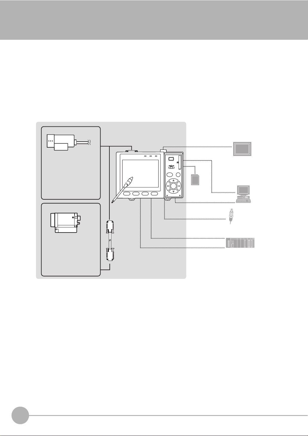
System Configuration
Basically, the ZFX-C is configured by the Controller and the camera.
Other external devices can be selected to be used in combination with the ZFX-C according to the user’s
specific requirements.
Cameras with lighting
(cable built-in)
- Color camera
ZFX-SC10/SC50/SC50W
ZFX-SC90/SC90W
ZFX-SC150/SC150W
- Monochrome camera
ZFX-SR10/SR50
Camera only
- Color camera
ZFX-SC
- Monochrome camera
ZFX-S
A CCTV lens and light
source will be required.
Touch pen
(*1)
Camera cable
ZFX-VS/VSR
Controller
ZFX-C_
Monitor cable
FZ-VM
SD Card (*4)
RS-232C cable
ZFX-XPT2A
RS-422 cable
ZFX-XPT2B
Parallel I/O cable
ZFX-VP
LCD monitor (option)
FZ-M08 (*2)
PC
USB
Ethemet
Console
ZFX-KP
PLC
(*3)
*1: The Touch Pen (ZFX-TP) is supplied with the Controller.
*2: The same image as in the Controller's LCD monitor can be displayed in the LCD monitor (option).
*3: The console can be used instead of the Controller's keys and menu buttons.
*4: Conforms to the SD Card “Physical layer specifications 1.01.”
File format: FAT16
14
ZFX-C
ZFX-C User’s Manual
Page 16
Options
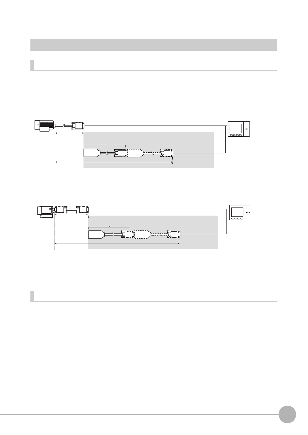
Extension cable for connecting cameras and the Controller
Cameras with lighting
1
BEFORE USE
Extension cable
(*1)
Extension cable
(*1,*2)
(cable built-in)
Camera only
Camera cable
ZFX-VS/VSR
2 m
5 to 18 m
3 m/8 m
8 to 19 m
ZFX-XC_A/XC_AR
3m/8m
ZFX-XC_A/XC_AR
3m/8m
*1: Up to two ZFX-XC_A/XC-AR can be connected between the camera cable and the Controller.
*2: Two ZFX-XC8A cannot be connected to each other when used with ZFX-VS (8 m.)
Optional lighting
The following optional lighting can be connected to ZFX-SC50/SC50W/SC90/SC90W.
• Bar lighting ZFV-LTL01
• Bar double-lighting ZFV-LTL02
• Bar low-angle lighting ZFV-LTL04
• Light Source for Through-beam Lighting ZFV-LTF01
ZFX-C User’s Manual
ZFX-C
15
Page 17
Part Names and Functions
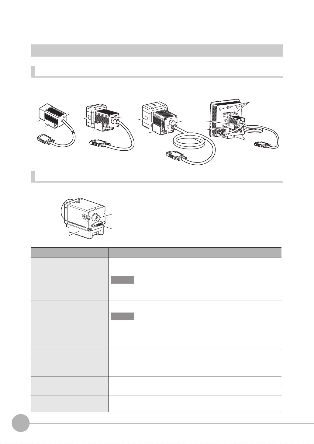
Cameras
Cameras with lighting
ZFXSC10/SR10/SR50
(2)
(4)
ZFX-SC50/SC50W
(3)
(2)
(4)
(3)
(1)
ZFX-SC90/SC90W ZFX-SC150/SC150W
(2)
(4)
(3)
(1)
(3)
(4)
(2)
(2)
Camera only (C-mount type)
ZFX-S/SC
(5)
(6)
(7)
Name. Description
(1)Optional lighting connector This connector is used to connect an optional lighting. (ZFX-SC50/SC50W/
SC90/SC90W)
Important
When no optional lighting is used, make sure that the connector is covered with
the cap. If not, water-resistant performance will be deteriorated.
(2)Ventilation film This film prevents the front panel from condensation.
Important
• Do not peel off or probe the ventilation film with a sharp-pointed object. If you
do that the protective structure rating may no longer be satisfied.
• Do not cover the ventilation film rating. Doing so might cause the front panel
to be condensed.
(3)Focus adjustment control This control is used for adjusting the focus of the image.
(4)Mounting fixture This mounting fixture is used for fastening the camera when installing it. The
mounting fixture can be installed on all of the four mounting surfaces.
(5)Lighting connector This connector is used to connect an external lighting (Strobe Controller).
(6)Camera cable connector
(7)Camera mounting base
This connector is used for connecting to the Controller via a camera cable (ZFX-VS/VSR).
This camera mounting base is fastened with screws to hold the camera in place. The camera
mounting base can be installed on all of the four mounting surfaces.
16
ZFX-C
ZFX-C User’s Manual
Page 18
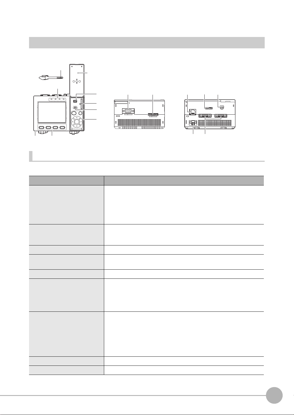
Controller
Front
(4)
Operation
panel cover
Top
Bottom
(1)
(2)
CAMERA1
CAMERA2
(1)
ETHERNET
(2) (3)
RS-232C
PARALLEL1
CONSOLE
PARALLEL0
(4) (5)
(9)
OMRON
ZFX-C10
OUTPUT
RUN
(2)
1234
(3)
USB
ENABLE
ERROR
ADJ
MENU RUN
AUTO ESC
SET
PULL OPEN
SD
CARD
(5)
(6)
(7)
(8)
(1)
RGB
Front
Name Function
(1) Indicator “Measuring” indicator (RUN): Lights in green when in the RUN mode.
Error indicator (ERROR): Lights in red when an error occurs.
Judgment indicator (OUTPUT): Lights in orange when the judgment result is
OK or NG according to the setting. (Note)
Trigger indicator (ENABLE): Lights in blue when the ZFX-C is ready for the
measurement trigger input.
(2) LCD monitor/touch panel The LCD monitor displays setup menus and images captured from the cam-
eras. Various settings can be made on the touch panel by tapping menu buttons in the LCD monitor using the touch pen.
(3) Function keys Specific functions are allocated to the Function keys.
(4) Touch pen The touch pen is used to operate the touch panel. This pen can be attached to
the Controller by tying its strap to the strap holder for the touch pen.
(5) USB port This port is for connecting to a personal computer via a USB cable.
(6) SD card slot This slot is for inserting the SD Card.
When the SD Card is inserted, the SD mark is displayed at the top right of the
screen.
Blue SD mark: The SD card is inserted but not being accessed.
Red SD mark: The SD card is being accessed.
(7) Mode switch This switch selects the operation mode.
MENU: Select this mode when setting measurement conditions.
ADJ: Select this mode when adjusting setting parameters as necessary refer-
encing the image and values displayed on the LCD monitor during continuous test measurement (measurement without measurement data
output to external devices).
RUN: Select this mode when performing measurement.
(8) Control keys These keys are used to perform operations without the use of the touch pen.
(9) Strap holder for touch pen This holder is for attaching the touch pen.
1
BEFORE USE
Note: The judgment result is output to the OR signal via the parallel interface.
ZFX-C User’s Manual
ZFX-C
17
Page 19
Top
Name Function
(1) Monitor connector This connector is for connecting to the LCD monitor (option) via a monitor
cable.
(2) Camera connector This connector is for connecting to a camera.
Bottom
Name Function
(1) Ethernet port This port is for connecting to a personal computer via a 100Base-TX/10Base-T
cable.
(2) RS-232C/422 connector This connector is for connecting to a PLC via an RS-232C or an RS-422
cable.
(3) Console connector
(4) Power connector
(5)Parallel port This port is for connecting to devices such as a PLC using the parallel
This port is for connecting to the Console.
This connector is for connecting to the DC power supply.
cable. p.14
p.14
p.14
p.28
, p.126
Important
• Attach the connector caps to connectors that are not in use to prevent dust or dirt from getting inside the connectors
and to prevent the Controller from static electricity.
18
ZFX-C
ZFX-C User’s Manual
Page 20
Mounting and Connecting Devices
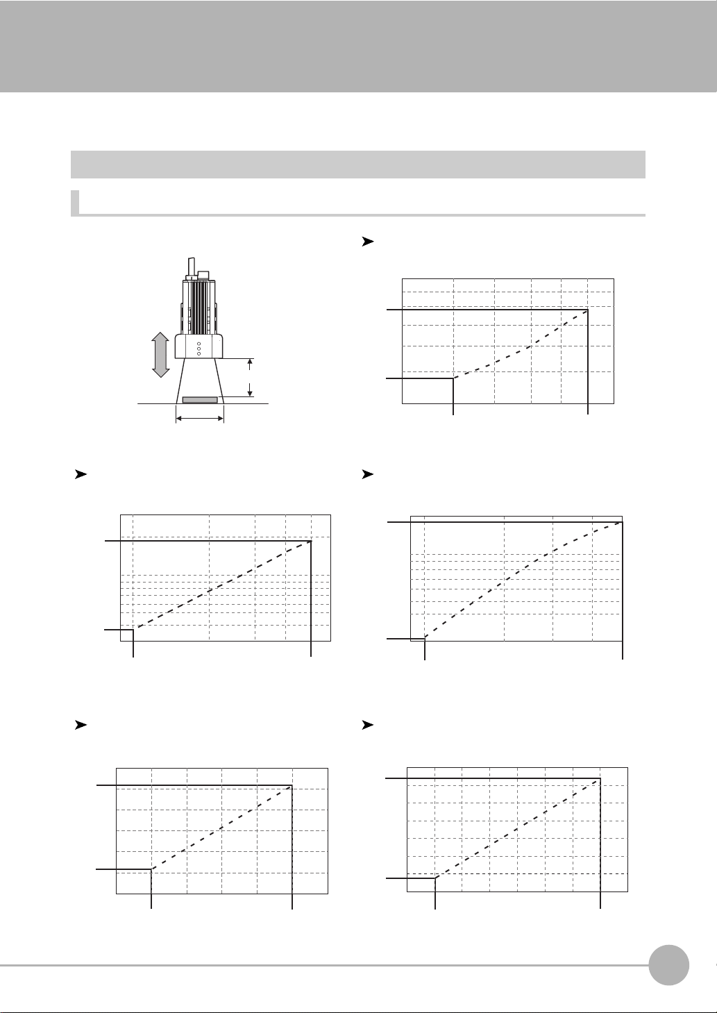
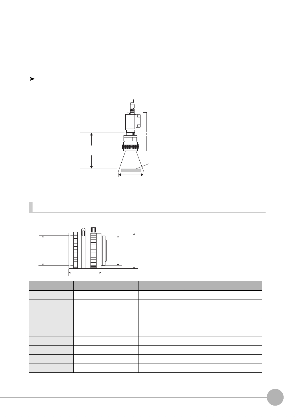
Installing Cameras
Camera with Lighting
Optical chart
ZFX-SC10/SR10
Setting distance L (mm)
60
50
49
Setting distance (L)
Detection range (H)
ZFX-SR50 ZFX-SC50/SC50W
Setting distance L (mm)
300
194
100
34
0
5
Setting distance L (mm)
190
187
100
1
BEFORE USE
104
9
Detection range H (mm)
38
30
9
10 50
ZFX-SC90/SC90W ZFX-SC150/SC150W
Setting distance L (mm)
160
142
100
67
40
50
ZFX-C User’s Manual
Detection range H (mm)
70
Detection range H (mm)
60
10040
90
31
30
9
10
Setting distance L (mm)
240
227
180
115
100
90
Detection range H (mm)
12080
Detection range H (mm)
Mounting and Connecting Devices
50
160
150
19
Page 21
Note
• The lens has a fixed focal point. The actual detection range and focal point vary from lens to lens, so adjust the
distance to the measurement target after replacing the lens or camera.
• The camera mounting distance listed in the following tables is an approximate value. Mount the Camera so that
the distance to the measurement target can be adjusted easily.
• If the object size and detection range are incompatible, use a combination of a camera (without lighting), standard
CCTV lens and light source.
Camera Only p.22
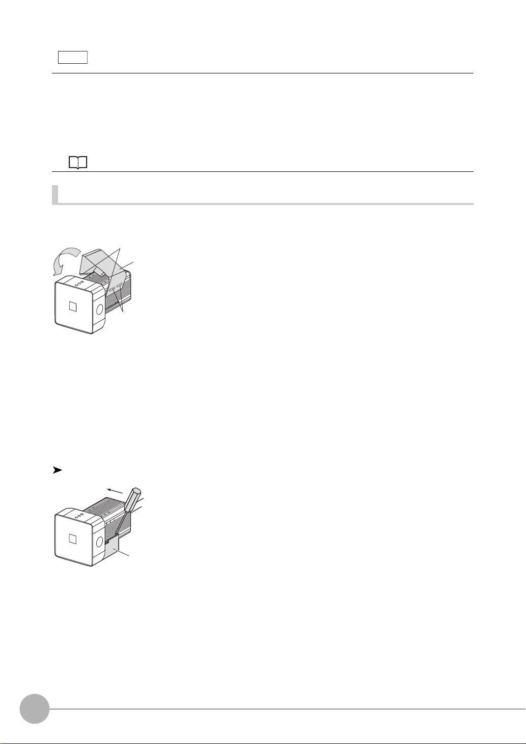
Installing the mounting fixture
The mounting fixture can be installed on all of the four mounting surfaces.
Hooks
Mounting
fixture
Grooves on camera
1 Align the two hooks on one side of the mounting fix-
ture with the two grooves on the camera body.
2 Push the other hook down until it is snapped into
place.
Make sure that the mounting fixture is firmly fixed on the
camera.
3 Fasten the mounting fixture at the mounting location
with screws.
Tightening torque
M4: 1.2 N•m
1/4”-20 UNC: 2.6 N•m
Removal procedure
Mounting fixture
20
Mounting and Connecting Devices
1 Insert a screwdriver into the gap (one of the two gaps) be-
tween the mounting fixture and the camera case, and re-
move the mounting fixture
.
ZFX-C User’s Manual
Page 22
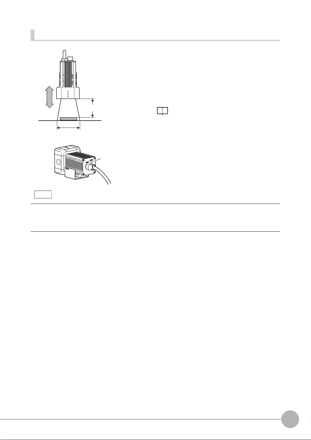
Adjusting the camera focus
1 Adjust the distance between the camera and the mea-
surement target and fasten the camera.
Refer to the optical chart and set the camera in a position
so that the area to be checked is within the detection area
(LCD monitor).
Setting distance (L)
Detection range (H)
Focus
adjustment
control
Note
First turn the focus adjustment control slightly to the left and right, to make sure that the Focus adjustment control is
not at the upper or lower limit positions. Do not exert unnecessary force to turn the control at the upper or lower limit
positions as this might damage the control.
(For ZFX-SC90_/SC150_, the control stops turning at the nearest position. It turns free at the farthest position.)
2 Turn the focus adjustment control to the left and right
Optical chart p.19
to adjust the focus.
1
BEFORE USE
ZFX-C User’s Manual
Mounting and Connecting Devices
21
Page 23
Camera Only
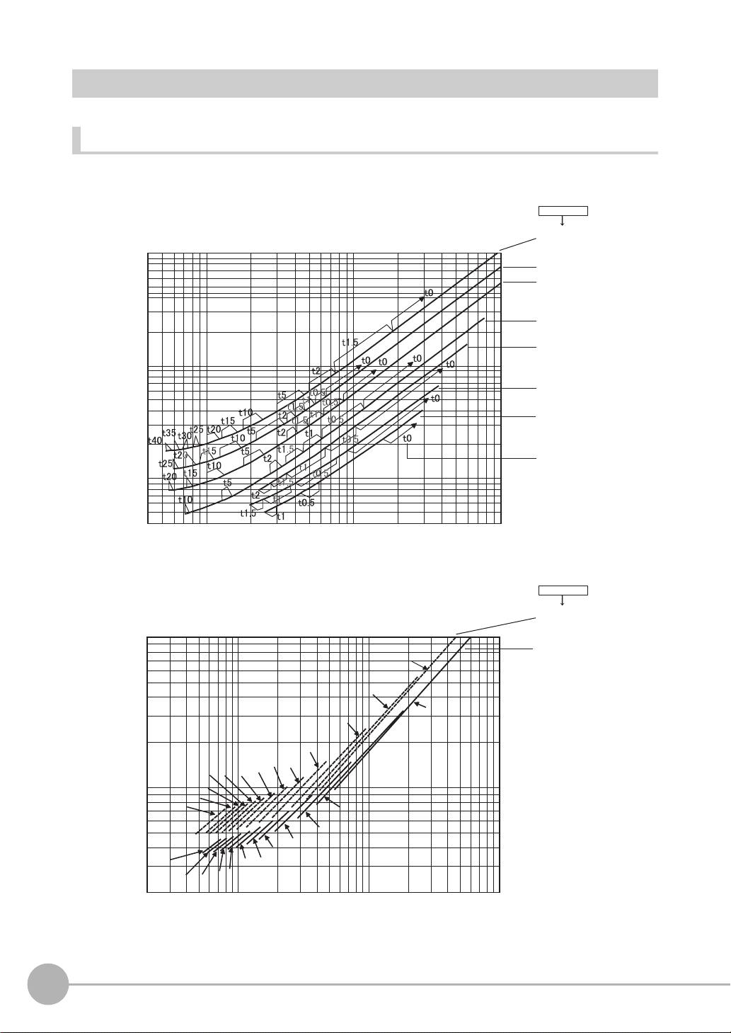
Optical chart
The values in the following chart are approximations, and the Camera must be adjusted after it is mounted.
Lens model
3Z4S-LE
ML-5018
10000
ML-3519
ML-2514
ML-1614
Camera distance A(mm)Camera distance A(mm)
1000
10000
1000
200
100
40
4 10 100 1000
Detection range(mm)
t0
t2
t0
t50
t60
t45
t50
t40
t45
t40
t35
t35
t30
t30
t25
t25
t20
t20
t15
t5
t10
t15
t2
t5
t10
2 10 100 1000
ML-1214
ML-0813
ML-0614
t: Extension tube
Example
t0: Extension tube
is not required.
t5: 5-mm extension
tube is required.
Lens model
3Z4S-LE
ML-10035
ML-7527
22
Mounting and Connecting Devices
ZFX-C User’s Manual
Page 24
The X axis of the optical chart shows detection range L (mm), and the Y axis shows the camera distance A
(mm). The curves on the optical chart show the relationship between the detection range and camera distance
for each CCTV lens. The values are significantly different for each lens, so double-check the model of the lens
before using the graph. The “t” values indicate the lengths of the Extension Tubes. The value “t0” shows the
case where an Extension Tube is not required and the value “t5.0” shows the case where a 5-mm Extension
Tube is used.
1
Example
When a 3Z4S-LE ML-5018 CCTV Lens is being used and a detection range of 40 mm is required at the
measurement target, a camera distance of 500 mm and 5-mm Extension Tube are required.
Camera
Extension Tube t_ (mm)
Lens
Camera distance A (mm)
Measurement object
Detection range L (mm)
Lenses and lens diameters
BEFORE USE
Filter thread
Total length
1-32 UNF
(C-mount
thread)
Lens Focal length Brightness
3Z4S-LE ML-0614 6 mm F1.4 30 mm dia. 30 mm M27 P0.5
3Z4S-LE ML-0813 8 mm F1.3 30 mm dia. 34.5 mm M25.5 P0.5
3Z4S-LE ML-1214 12 mm F1.4 30 mm dia. 34.5 mm M27 P0.5
3Z4S-LE ML-1614 16 mm F1.4 30 mm dia. 24.5 mm M27 P0.5
3Z4S-LE ML-2514 25 mm F1.4 30 mm dia. 24.5 mm M27 P0.5
3Z4S-LE ML-3519 35 mm F1.9 30 mm dia. 29 mm M27 P0.5
3Z4S-LE ML-5018 50 mm F1.8 32 mm dia. 37 mm M30.5 P0.5
3Z4S-LE ML-7527 75 mm F2.7 32 mm dia. 42.5 mm M30.5 P0.5
3Z4S-LE ML-10035 100 mm F3.5 32 mm dia. 43.9 mm M30.5 P0.5
ZFX-C User’s Manual
Max. dia.
Maximum outer diameter
Total length Filter size
Mounting and Connecting Devices
23
Page 25
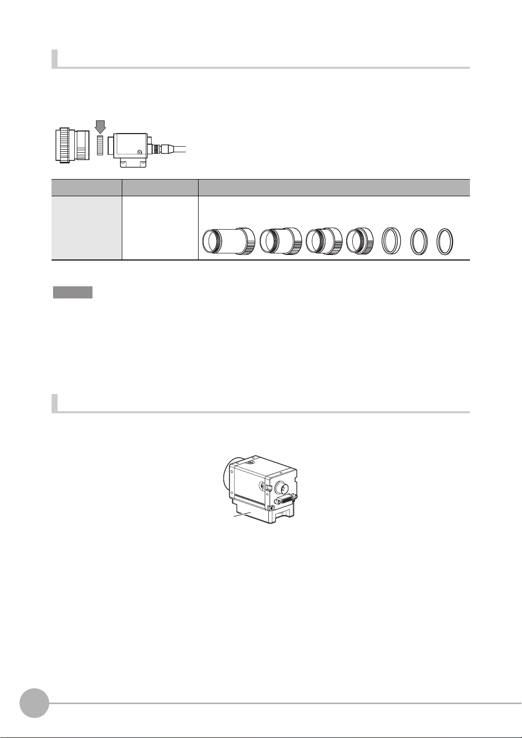
Extension Tubes
One or more Extension Tubes can be inserted between the lens and the Camera to focus the Camera image.
Use a combination of one or more of the seven tubes to achieve the required length.
Extension Tube
Model
3Z4S-LE ML-EXR 31 dia. Set of 7 tubes
Important
• Do not use the 0.5-mm, 1.0-mm and 2.0-mm Extension Tubes attached to each other. Since these Extension Tubes
are placed over the threaded section of the Lens or other Extension Tube, the connection may loosen when more
than one 0.5-mm, 1.0-mm or 2.0-mm Extension Tube are used together.
• Reinforcement may be required for combinations of Extension Tubes exceeding 30 mm if the Camera is subject to
vibration.
Maximum outer diameter
Length
Length: 40 mm 20 mm 10 mm 5 mm 1 mm2 mm 0.5 mm
Installing the Camera Mounting Base
The camera mounting base mounted on the bottom of the camera can be installed on all of the four mounting
surfaces. To change the mounting surface, remove the three mounting screws (M2 x 6) from the camera.
Camera Mounting Base
• Tightening torque when fastening the camera mounting base at the mounting location
M4: 1.2 N•m
1/4”-20 UNC: 2.6 N•m
24
Mounting and Connecting Devices
ZFX-C User’s Manual
Page 26
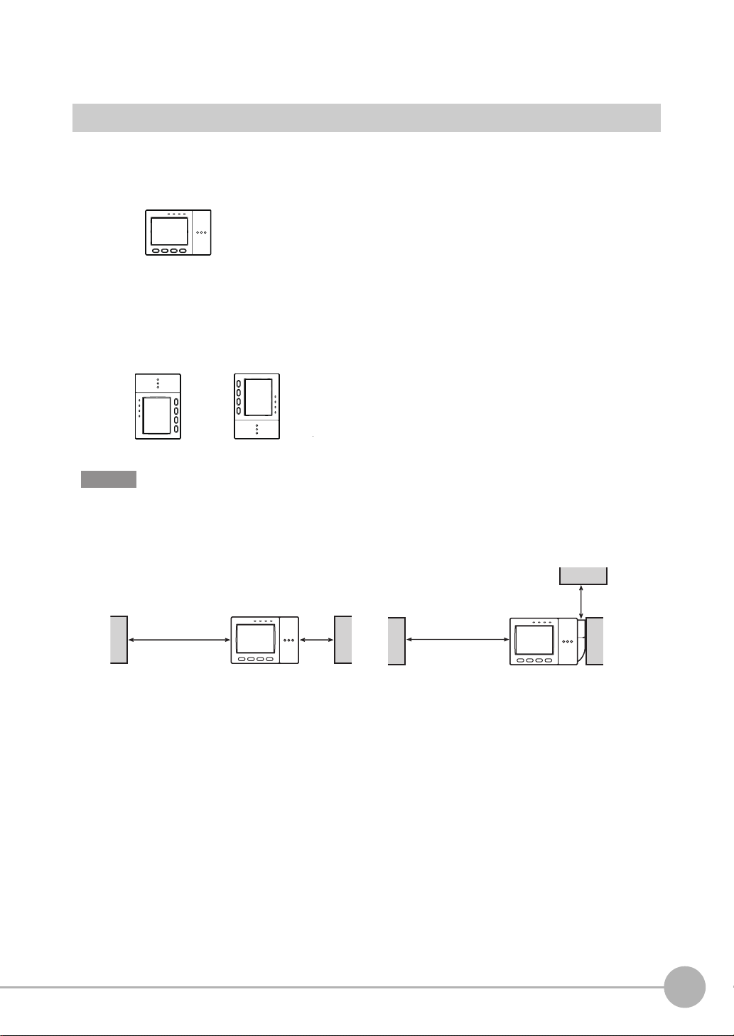
Installing the Controller
Installation Precautions
To improve heat radiation, install the Controller only in the orientation show below.
1
Right
Do not install the Controller in the following orientations.
Wrong Wrong
Important
• Install the Controller so that the distance between the Controller and other devices is at least the dimensions shown
in the figure below to improve the ventilation.
When installing Controller only:
When installing the Controller With the Exhaust Unit
attached:
Min. 15 mm
BEFORE USE
Min.
50 mm
• Keep the ambient temperature less than 50 °C. If the ambient temperature is higher than 50 °C, install a fan forced
cooling system or an air conditioner to keep the temperature lower than 50 °C.
• Avoid mounting on a panel, in which high-voltage emitting devices are installed to prevent ZFX-C operation from
being affected by noise.
• Allow at least 10 m between the Controller and power lines to keep noise at a low level in the operating environ-
ment.
ZFX-C User’s Manual
Min.
15 mm
Min.
50 mm
Mounting and Connecting Devices
25
Page 27
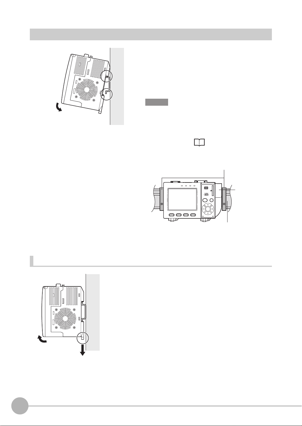
Installing on the DIN Track
1 Hook the Controller’s upper hook onto the DIN track.
1
2 Push the Controller down onto the DIN track until its
lower hook is snapped into place.
2
Important
•Attach the End Plate (sold separately) to both sides of the
Controller on the DIN track.
•Attach the Exhaust Unit (supplied) to the Controller when
installing other devices adjacently on the same DIN track
as the Controller.
OMRON
OUTPUT
ZFX-C10
1234
RUN
p.20
End Plate (sold separately)
PFP-M
USB
ENABLE
ERROR
ADJ
MENU RUN
AUTO ESC
SET
PULL OPEN
SD
CARD
Exhaust Unit
DIN track (sold separately)
PFP-100N (1 m)
PFP-50N (0.5 m)
PFP-100N2 (1 m)
Removing procedure
2
26
Mounting and Connecting Devices
1 Pull the Controller’s lower hook downwards.
2 Lift up the Controller from its bottom to remove it from
the DIN track.
1
ZFX-C User’s Manual
Page 28
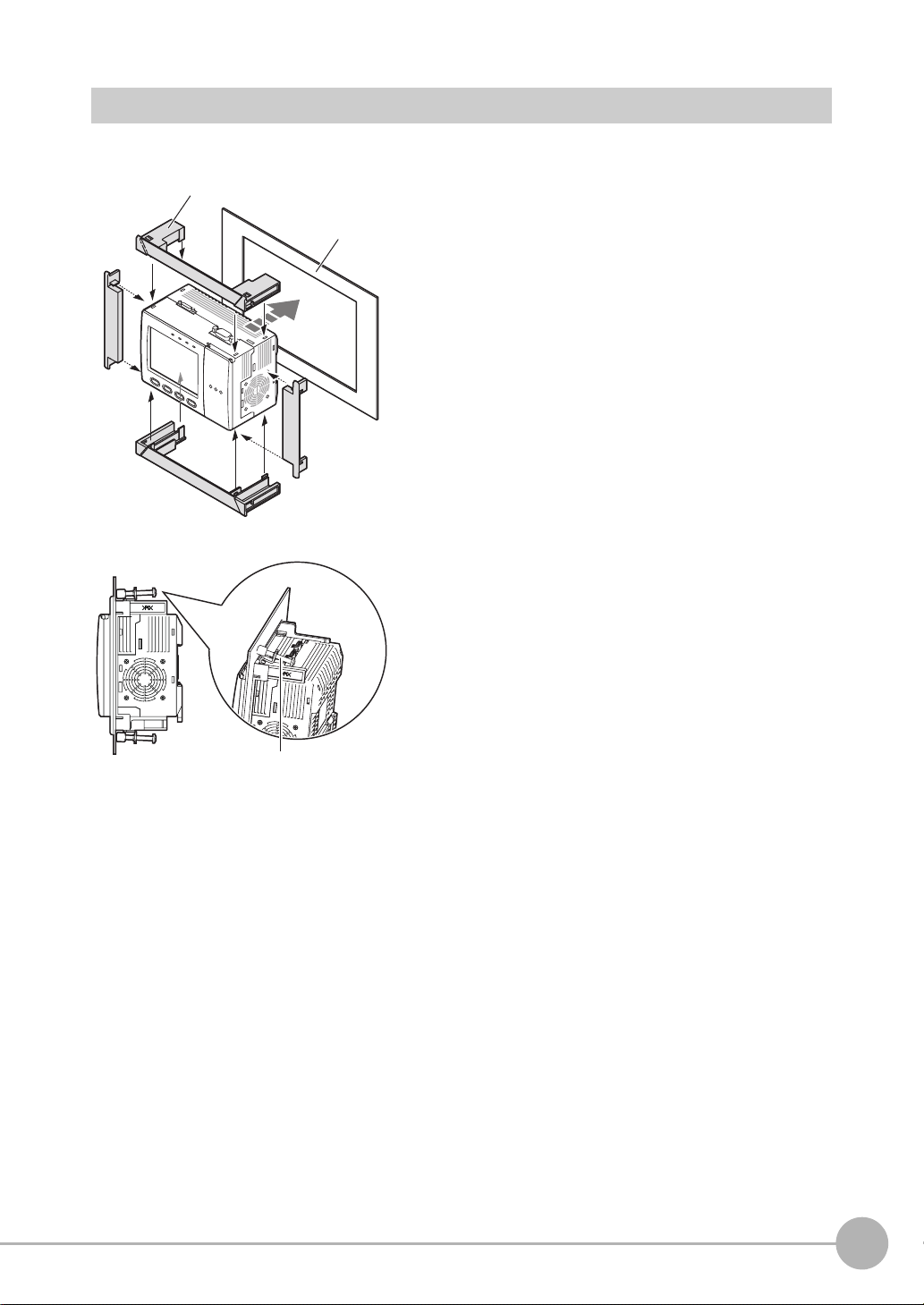
Mounting on a Panel
Panel mount adapters
1
Panel
1 Install the long Panel Mount Adapters on the four
holes on the Controller.
1
BEFORE USE
3
2
holes on the long Panel Mount Adapter.
3 Install the Controller with Mount Adapters attached
2 Install the short Panel Mount Adapters on the two
onto the panel from the front.
2
1
4 Hook the hooks of the mounting bracket onto the two
4
holes of the longer Mount Adapters and tighten the
screws.
Tightening torque: 1.2 N•m.
5 Make sure that the Controller is firmly fixed on the
Mounting bracket
panel.
ZFX-C User’s Manual
Mounting and Connecting Devices
27
Page 29
Connecting Devices
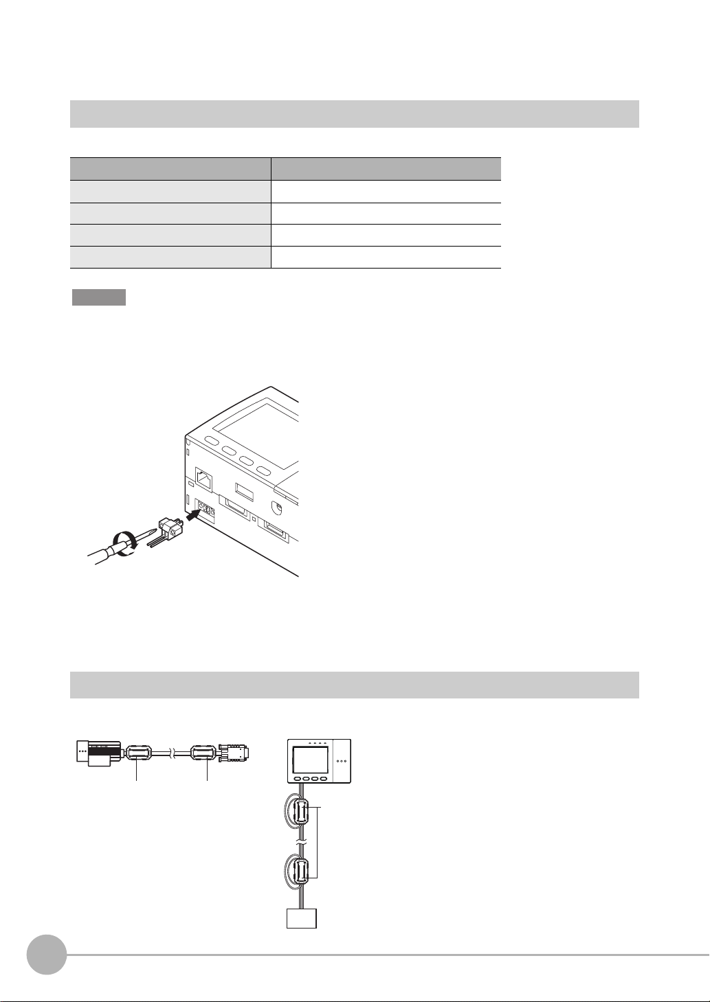
Connecting the Controller to the Power Supply
Use a power supply that meets the following specifications.
Item Specification
Power supply voltage Approx. 24 VDC (21.6 to 26.4 VDC)
Output current 1.0 A min.
Recommended power supply S8VS-06024 (24 VDC, 2.5 A)
Recommended electric wire size 0.14 to 1.5 mm2 (max. 1 m)
Important
Use a DC power supply with countermeasures against high voltages (safe extra low-voltage circuits on the secondary
side). If the system must meet UL standards, use a UL class II power supply.
1 Loosen the two screws on the top of the Power con-
nector (male) using a flat-blade screwdriver.
2 Insert the DC power terminal (wire) into the Power
connector (male) and tighten the two screws on the
top of the Power connector to fasten the power terminal with the screwdriver.
+
-
24 VDC
Tightening torque: 0.22 to 0.25 N•m.
3 Plug the Power connector (male) into the Controller’s
Power connector (female).
4
Tighten the two screws on the left and right of the Power
connector (male) with the screwdriver to fasten it.
Tightening torque: 0.22 to 0.25 N•m.
Attaching Ferrite Cores
Attach ferrite cores (supplied) to both ends of the camera's cable and the Controller's power cable, respectively.
Ferrite coreFerrite core
Ferrte core
When attaching ferrite cores to the Controller's power
cable, pass the cable once through each ferrite core.
-
+
DC power
supply
28
Mounting and Connecting Devices
ZFX-C User’s Manual
Page 30
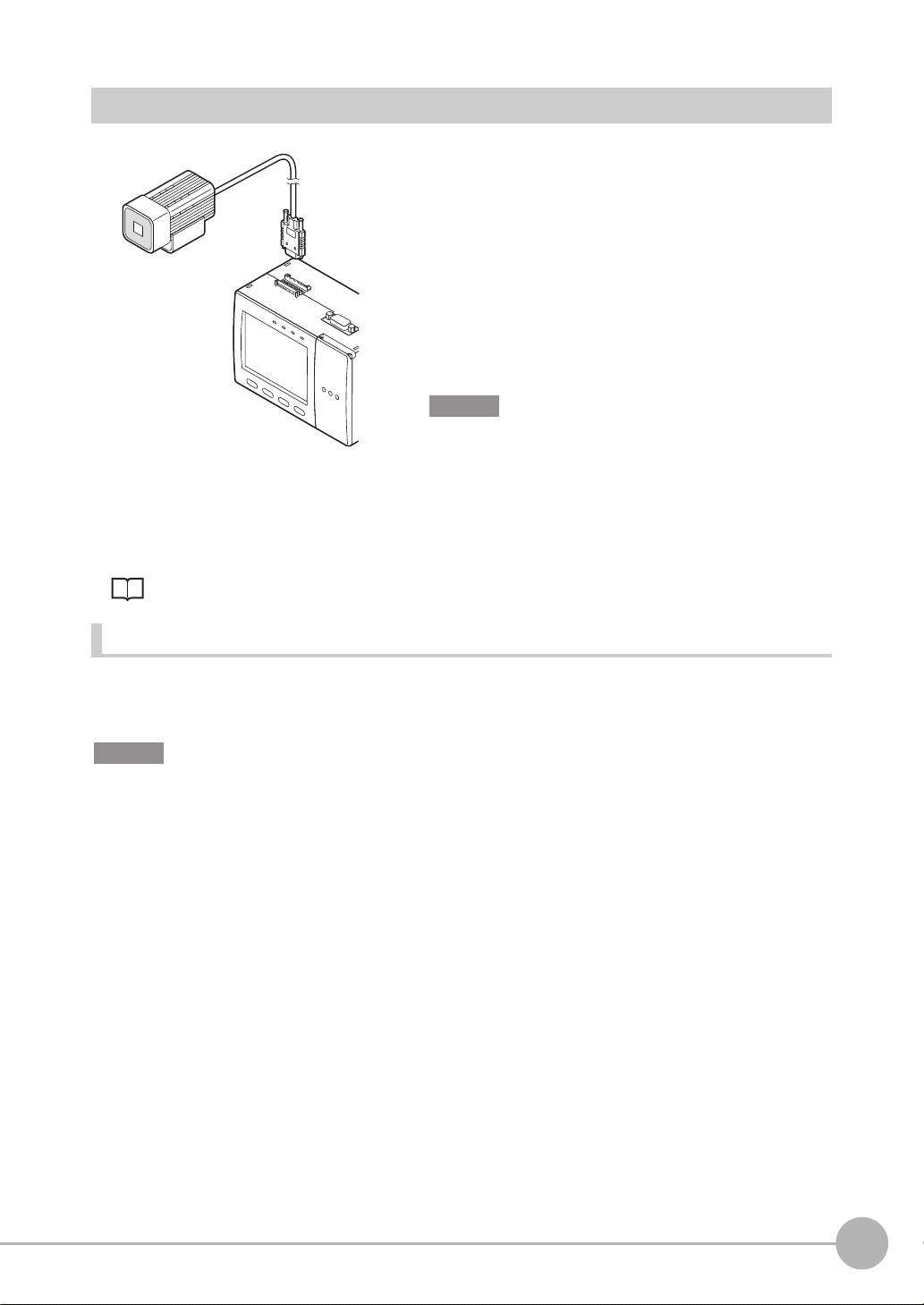
Connecting the Camera to the Controller
1Insert the camera’s connector into the Controller’s
Camera connector.
Make sure that you hear the connector snap firmly into
place when it is connected.
2Tighten the two fastening screws of the Controller’s
Camera connector.
Tightening torque: 0.15 N•m.
Important
•Do not touch the terminals inside the connector.
•Fasten the connector while making sure that it is not subjected
to vibration or shock.
•Do not mount the Controller in such a way that a load is steadily
applied on the connector, for example, with tension applied to
the cables.
To extend the installation distance between cameras and the Controller, see p.15
1
BEFORE USE
Disconnection procedure
Loosen the fastening screws (two locations) to unlock the camera’s cable, and then pull the camera’s cable
connector straight out.
Important
• Be sure to hold the connector of the camera to disconnect it. Failure to do so may damage the camera’s cable.
• Do not touch the terminals inside the connector.
ZFX-C User’s Manual
Mounting and Connecting Devices
29
Page 31

Connecting the Optional Lighting to the Camera
The optional lighting can be mounted to the rear connector of the camera (ZFX-SC50_/SC90_) with a single
motion. Since the power is supplied from the camera side, no power supply is required for the optional lighting.
Remove the cap from the optional lighting connector on the rear of the camera.
Connector of the
optional lighting
Attaching the Exhaust Unit to the Controller
Attach the Exhaust Unit (supplied) to the Controller when installing other devices next to the Controller on the same
DIN track. The Exhaust Unit also serves as the Touch Pen Holder
Touch Pen Holder
Exhaust Unit
1 Attach the Exhaust Unit to the four mounting holes on
the Controller.
30
Mounting and Connecting Devices
ZFX-C User’s Manual
Page 32

Overview of Settings and Measurement
ADJ
MENU
RUN
Operation Modes
The ZFX-C has the following three modes. Switch to the desired
MENU
ADJ
RUN
mode before you start operation. To switch the operation mode,
use the mode switch.
Mode switch
Mode Description
MENU mode This mode is for setting the measurement
conditions. The easy-to-follow icon-based
display allows operations to be performed
intuitively.
ADJ mode This mode is for checking the measure-
ment status and adjusting conditions.
Measurement results are only displayed
on the monitor and are not output.
Top Screen
LIVE
Bank
Tool
Top Screen
353ms
OK
0.Bank00
0.Pattern Search
Judge OK
Correlation 92
Position X 462
Position Y 352
Angle 15
Top menu
TEA
System
Setup
Individual result
1
BEFORE USE
Save
TEA
RUN mode This mode is used for performing actual
measurement. Measurement results are
displayed on the monitor and output.
ZFX-C User’s Manual
Previous Next
Dsplay SW
Adjust
Top Screen
Individual result
353ms
OK
0.Bank00
0.Pattern Search
Judge OK
Correlation 92
Position X 462
Position Y 352
Angle 15
Previous Next
TEA
Dsplay SW
Capture
Overview of Settings and Measurement
31
Page 33

Outline of MENU mode
The MENU mode is broadly divided into three levels. The icons used for basic setup are displayed in the
center.
Use icons other than those in the center whenever required.
These menus are displayed when the Controller is turned
To p Menu
on.
Top menu
Tool
Bank
Setup
System
Save
Setup Menu
These menus are used for setting measurement
conditions.
Setup
Cameras
Register
Item
Position
Top Menu
Add func
This returns to the top menu.
This selects measurement items and sets the measurement region. Up to 128 measurement regions can be set.
32
Overview of Settings and Measurement
Measurement item Menu
Select measurement item
Img Adj
Region
Detail
Setup menu
Limits
This returns to the setup menu.
ZFX-C User’s Manual
Page 34

Measurement Items and Banks
Measuring Multiple Locations
Up to 32 locations in a single measurement image can be measured. A measurement type is called an "item,"
and desired measurement types are assigned to items 0 to 31.
1
Cap color
(item 0: Hue inspection)
Label attached state
(item 1: Pattern Search)
Label lettering
(item 2: Sensitive Search)
Data for Change of Device Setup
If you register bank data for each individual product, you can reduce the time required for changing the device
setup as all you need to do is to select different bank data to change the measurement conditions.
Bank 0Bank 2 Bank 3 Bank 31
For inspection of
product A
For inspection of
product B
For inspection of
product C
For inspection of
product Z
BEFORE USE
ZFX-C User’s Manual
Overview of Settings and Measurement
33
Page 35

Relationship between Items and Bank Data
Up to 32 items can be registered to a single bank data. Up to 32 bank data can be set to and saved on the ZFX.
Bank 0
.
Position correction function
setup information
.
Output condition setup
information
Bank 1
Bank 2
Bank 31
Note
• If you use the bank group function, you can set up to 1024 banks.
Item 0
.
Region information
.
Measurement item information
.
Image adjustment information
.
Judgment threshold value information
Item 1
Item 2
Item 31
Bank Settings p.108
• Bank and items can be given any name up to 16 characters.
Bank and item names make it easier to recognize which measurement is being performed when multiple items
and banks have been set.
34
Overview of Settings and Measurement
ZFX-C User’s Manual
Page 36

Initializing Controller Settings
ADJ
MENU
RUN
Important
The settings of all banks and system settings (excluding the display language setting) are initialized regardless of the
currently selected bank No. To save the settings, back them up to a SD card before performing initialization.
Saving/Loading Data p.121
1
BEFORE USE
LIVE
Bank
Tool
Initialize controller
All stored image
Reset the controller to
factory default settings.
Measure
Startup
ADJ
MENU
Top menu
TEA
OK Cancel
Language
Setup
System
RUN
System
Date
Mode switch
SD
Save
SD
Init.
1 Switch to the [MENU] mode.
The top screen is displayed.
2 Select the [System] icon.
3 Select the [Init] icon.
4 Select [Initialize controller].
ZFX-C User’s Manual
5 Select [OK].
Overview of Settings and Measurement
35
Page 37

Saving Setup Data
ADJ
MENU
RUN
After you have set the measurement conditions, be sure to save the setup data.
Important
All settings will be deleted if you turn the power OFF without saving the data.
ADJ
MENU
Top menu
LIVE
TEA
Bank
Tool
Setup
Setting Data will be saved.
OK Cancel
RUN
Mode switch
System
Save
1 Switch to the [MENU] mode.
The top screen is displayed.
SD
2 Select the [Save] icon.
3 Select [OK].
Note
Data Saved on the Controller
Bank settings and system settings are saved internally on the Controller. Image data is not saved on the Controller.
Save image data on the SD card.
When Using the Bank Group Function
Bank data that is set to bank group 0 is saved internally on the Controller. When the bank data of bank groups 1 to
31 is saved, the bank data on the SD card is overwritten with the bank data of bank groups 1 to 31.
36
Overview of Settings and Measurement
ZFX-C User’s Manual
Page 38

BASIC OPERATIONS
Inspection Setup and Measurement 38
Setting Measurement Conditions - MENU Mode 38
Checking the Measurement Status - ADJ Mode 42
Starting Measurement - RUN Mode 42
Troubleshooting 43
Clear Images Cannot be Obtained 43
Measurement Target Cannot be Measured Accurately Due to
Movement
To Output Measurement Values to a PC or PLC 44
To Output Position Information of Measurement Targets as
Actual Coordinates 44
2
BASIC OPERATIONS
43
Page 39

Inspection Setup and Measurement
The following describes the flow of basic setup using, as an example, inspection of whether different types of
objects are mixed in.
OK NG
Setting Measurement Conditions - MENU Mode
On the ZFX, a 3-step operation completes basic inspection setup.
step1
Selecting measurement
items
Shape
Size
Edge
Bright&Color
Application
Cameras
Measurement
type group
Register
Pattern
Position
Item
Sensiti.
Add func
Measurement
Measurement
items
items
step2
Setting measurement
regions
New
Enclose the desired measurement
area.
Move [130,140]
TEA
step3
Executing automatic
setting
Register model
Reference model
Search region
Reference point
Img Adj
AUTO
The optimum measurement
conditions are automatically set just
by selecting [AUTO].
Measurement conditions can al so be
checked and changed.
Region
Detail
TEA
Limits
38
Inspection Setup and Measurement
ZFX-C User’s Manual
Page 40

step 1
ADJ
MENU
RUN
Selecting measurement items
Tool
Shape
Size
Edge
Bright&Color
Application
LIVE
Bank
MENU
ADJ
Top menu
TEA
Setup
Pattern
RUN
Mode switch
System
Save
Sensiti.
1 Switch to the MENU mode.
The top screen is displayed.
2
BASIC OPERATIONS
2 Select the [Setup] icon.
3 Select [Shape].
Cameras
Register
Item
Position
Add func
4 Select the [Pattern] icon.
Note
For details on types of measurement items, see "Setting
Measurement Conditions" in Chapter 3.
ZFX-C User’s Manual
Inspection Setup and Measurement
39
Page 41

step 2
Setting measurement regions
Register model
Reference model
Search region
Reference point
Inspect
Circle
Box
Circum
Polygon
Inspect
New
Img Adj
Img Adj
Elipse
Region
Region
Move
TEA
Detail
Detail
1 Select [Register model].
TEA
Limits
2 Select [Box].
TEA
Limits
[130,140]
3 Enclose the desired measurement area.
First, move the region. Next, select [Size] and apply the
size.
Note
Size Apply Cancel
The location of the region can be changed or the region
resized by the amount of drag movement if you drag anywhere on screen. (The drag start position need not be the
line of the region.) To set a region on top of [Cancel] or
other buttons at the bottom of the screen, drag somewhere
else on screen.
Setting the Region p.174
4 Select [Apply].
40
Inspection Setup and Measurement
ZFX-C User’s Manual
Page 42

step 3
AUTO
ESC
Executing automatic setting
AUTO
ESC
Register model
Reference model
Search region
Reference point
Img Adj
Auto
AUTO key
Region
Detail
1 Either press the AUTO key on the controller or select
[AUTO] on screen.
Note
When the automatic setting is executed, the following
parameters are set to their optimum values.
• Img Adj (filter setup)
TEA
• Limits (Differs according to measurement item.)
• Detail (Differs according to measurement item.)
Automatically made settings can be checked in each of the
Limits
setup screens.
AUTO Setting p.148
2
BASIC OPERATIONS
ZFX-C User’s Manual
Inspection Setup and Measurement
41
Page 43

Checking the Measurement Status - ADJ Mode
ADJ
MENU
RUN
ADJ
MENU
RUN
Check whether or not measurement can be performed accurately under the conditions you have set, and
adjust threshold values. Measurement results are only displayed on screen and are not output to external
devices.
ADJ
MENU
OK
0.Bank00
0.Pattern Search
Judge OK
Correlation 92
Position X 462
Position Y 352
Angle 15
353ms
RUN
Mode switch
Individual result
TEA
1 Select the ADJ mode.
The results of continuous measurement are displayed on
screen. Make sure that measurement can be performed
accurately and stably.
Previous Next
Dsplay SW
Adjust
Starting Measurement - RUN Mode
When you have checked the measurement conditions you have set, use the RUN mode to perform
measurement. In the RUN mode, measurement results are also output to external devices.
ADJ
MENU
RUN
1 Select the RUN mode.
Mode switch
2 Input the trigger.
Measurement is executed.
Input the trigger using the SET and UP keys.
Note
In the RUN mode, you can switch the display content to
check various information.
Switching display content
Displaying Measurement Information p.100
Important
After you have set the measurement conditions, be sure to save the setup data. All settings will be deleted if you turn
the power OFF without saving the data.
Saving Setup Data p.36
42
Inspection Setup and Measurement
ZFX-C User’s Manual
Page 44

Troubleshooting
Clear Images Cannot be Obtained
Measurement sometimes cannot be performed successfully (e.g. measurement image is dark or contrast is
low) depending on the characteristics of the measurement target. Sharp images can be obtained by applying
filtering, or performing correction and adjustment to remedy the trouble.
Trouble Remedy Reference
Poor lighting The recipe method light control settings can be used. You can set the lighting
just by selecting the image that meets your specific requirements from the
thumbnails of images automatically taken under different lighting patterns.
Low contrast You can apply filters, such as "Sharpen", to the image to enhance the bound-
aries between shadow and highlight areas.
Uneven image • You can apply filters, such as "Smooth", to the image to smooth out
unevenness in the image.
• White parts of the image can be corrected to be reproduced appropriately
by adjusting the white balance.
Dark image You can raise the camera's sensitivity or lengthen the shutter time to make the
image brighter.
p.85
p.80
p.80, p.110
p.82, p.85
Measurement Target Cannot be Measured Accurately
Due to Movement
When the measurement target is moving (e.g. its position or orientation are not fixed), it moves out of the
preset measurement region, which prevents accurate measurement. The ZFX-C is provided with a "position
shift correction function" that corrects the position shift of measurement regions such as this before performing
measurement. The position shift correction function enables measurement targets whose position or
orientation is not fixed to be measured accurately.
2
BASIC OPERATIONS
Position Correction p.92
When setting the measurement
region (reference image)
Measurement region
ZFX-C User’s Manual
When the measurement target
moves out of position
The position of the measurement
target is measured after the measurement region is shifted by the
amount of position shift.
Troubleshooting
43
Page 45

To Output Measurement Values to a PC or PLC
Measurement values and judgment results can be output to a personal computer, PLC or other external device.
Set the items to output and the output destination.
The following data can be output.
Output Item Output Destination
Data (measurement values)
Judgment Parallel interface
• Setting Output Content p.114
• Assigning the Data Output Destination p.115
Serial interface (RS-232/RS-422, USB)
Parallel interface
SD card
To Output Position Information of Measurement
Targets as Actual Coordinates
As the controller default, measurement values are output in pixel units and camera coordinates. You can
convert measurement results in pixels to actual dimensions (
enabling the calibration function.
µm or mm) or actual coordinates for output by
Calibration p.86
44
Troubleshooting
ZFX-C User’s Manual
Page 46

SETTING THE MEASUREMENT CONDITIONS
3
Setting Measurement Items 46
Shape Inspection 46
Pattern Search 46
Sensitive Search 50
Size Inspection 54
Area 54
Edge Inspection 58
Position 58
Width 63
Count 66
Bright/Color Inspection 69
Bright 69
HUE 71
Inspection by Individual Application 74
Defect 74
Image Adjustment 78
Cameras/Lighting 82
Shutter Speed 82
Gain Setting 82
Partial Function Settings 83
Image Rate 84
Light Control (Recipe Functions) 85
Calibration 86
Registering Images 91
Position Correction 92
Additional Functions 94
Calculation 94
Setting Reflection of Individual Results 97
SETTING THE MEASUREMENT CONDITIONS
Page 47

Setting Measurement Items
Shape Inspection
Pattern Search
Register an image pattern in beforehand as a model, and search for parts that most resemble an already
registered model. The correlation indicating how much parts resemble each other, the position of the
measurement target, and their angle can be output. Use this function to check for whether different-type
products are mixed in, or to calculate the position of the measurement target.
Setup Measurement
Parts resembling the model are searched for.
Search region (region
for searching model)
Reference point
Model
(image pattern to find)
Region settings
This function sets the region to be registered as the model and the region to search for the model.
X MENU mode - [Setup] - [Item] - [Region]
Item Description
Register model This function registers the image pattern to find as the model.
Setting the Region p.174
Reference model The image that is registered as the model can be referenced.
Search region Set the region in which to search for the model.
Reference point Set the coordinates of which part of the model are to be output. The default is the center
position of the model.
46
Setting Measurement Items
ZFX-C User’s Manual
Page 48

Threshold
This function sets the judgment conditions.
X MENU mode - [Setup] - [Item] - [Limits]
Setup Item Description
Correlation Sets the range of the correlation to be judged as OK.
Range: 0 to 100
Position XY Sets the range of movement in the X- and Y- axes of the measurement target to be judged
as OK.
Range: -9999.999 to 9999.999
(When calibration is OFF, the range of movement for positions X and Y are 0 to 640 and 0
to 480, respectively.)
Angle Sets the range of rotation angle to be judged as OK.
Range: -180 to 180
-
0°
+
3
SETTING THE MEASUREMENT CONDITIONS
Search point
(enabled only when Verification is set to [ON])
Sets the number of search candidates to be judged as OK.
Range: 0 to 99
Image adjustment (if necessary)
The following items can be changed and set to the image of the measurement target.
X MENU mode - [Setup] - [Item] - [Img Adj]
Item Description
Color filter
Filtering
BGS* level
*BGS: Background Suppression
For details, see "Image Adjustment". p.78
ZFX-C User’s Manual
Setting Measurement Items
47
Page 49

Detailed settings (if necessary)
When measurement is not stable, adjust the detailed conditions.
X MENU mode - [Setup] - [Item] - [Detail]
Setup Item Setting value Description
Search mode Hi-speed The search is performed at high speed.
Normal (default value) The search is performed in the normal mode for both speed
and precision.
Precision The position is calculated at high precision in sub-pixel units
(units smaller than pixels).
Rotation range 0 to 180°
(default value: 0)
Skipping angle
Interpolation OFF (default value) Calculates the angle in skipping angle units.
Verification OFF (default value) The search is performed in detail near a candidate point having
Candidate level 0 to 100
Calibration OFF (default value)
1, 2, 3, 5, 10, 15, 20, 30°
(default value: 10°)
ON
ON The search is performed in detail near all candidate points.
(default value: 60)
ON Measurement results are output using the coordinate value
Sets in which angle range the model (rotated in degree units) is
to be created. The smaller the skipping angle that is set, the
higher the precision becomes, however, the longer the processing time becomes.
Important
When the rotation range and skipping angle have been
changed, register the model again.
The angle is calculated as a numerical value down to three digits
past the decimal point based on the value obtained in skipping
angle units. Note, however, that the processing time increases.
the highest correlation value.
Select [ON] when the model cannot be searched for stably.
Sets the level at which the model is searched for during a rough
search.
Images having a correlation value at the candidate level or
more are taken to the candidate points in the Verification. Set a
lower level when the model cannot be searched for stably.
Measurement results are output using the camera's coordinate values.
converted by the calibration function.
Note
A rough search is performed inside the search region to find the
candidate point.
48
Setting Measurement Items
Verification and candidate level
+
Verification ON
A detailed search is per-
+
+
+
Verification OFF
+
formed at images near all
candidate points.
A detailed search is performed at images near the candidate point having
the highest correlation.
ZFX-C User’s Manual
Page 50

Note
Models in the range set by Rotation range are created based on the registered model.
Example: When Rotation range is 15° and Skipping angle is 5°
Search Rotation Range
Registered model
-10°
-15°
Most similar model among these model is searched for.
Reference
-5°
5°
10°
15°
Possible output results
The following values can be output when expressions are set.
Item Description Message
Judgment result The judgment result is output. (0:OK, -1:NG, -2: not measured) Judge (JG)
Correlation The degree of match between the measurement image and model
image are output as a correlation value. (0 to 100)
Measurement position The X, Y coordinates of the position where the model was found are
output. (-9999.999 to 9999.999)
Measurement angle The rotation angle of the model that was found is output. (-180 to 180) Angle (TH)
Search number The number of searches that have a correlation value at the
correlation lower limit value or above is output. (0 to 99)
Reference position
Reference angle The angle when the model was registered is output. (-180 to 180) Ref. angle (ST)
Position difference The position difference obtained by "measurement position -
Angle difference The angle difference obtained by "measurement position - reference
The X, Y coordinates when the model was registered are output.
(-9999.999 to 9999.999)
reference position" is output. (-9999.999 to 9999.999)
position" is output. (-180 to 180)
Correlation (CR)
Position X, Y
(X, Y)
Search count (N)
Reference X, Y
(SX, SY)
Position dif. X, Y
(DX, DY)
Angle dif. (DT)
3
SETTING THE MEASUREMENT CONDITIONS
Note
Reference position = position of model when
Reference angle = angle of model when model
ZFX-C User’s Manual
Reference position/angle, position difference/angle difference
model is registered
is registered
Measurement position = position of model found by
measurement
Measurement angle = angle of model found by
measurement
Angle difference
= measurement angle -
reference angle
Position difference
= measurement position - reference position
Setting Measurement Items
49
Page 51

Sensitive Search
Use this item to detect minute differences. Models are automatically subdivided to check the degree of match
in detail. The correlation indicating how much parts resemble each other and the position of the measurement
target can be output.
Setup Measurement
Parts resembling the model are searched, and the degree
of match is checked in detail by subdivided models. When
subdivided models are a solid color, the solid color rate
also can be inspected.
Search region (region
for searching model)
Subdivision
Model
(image pattern to find)
Note
Example:
Measurement
count
Comparison with pattern search
Passed product
< Distribution of Measurement Results >
In a pattern search, a difference in correlation values
does not appear, making correlation values difficult to
distinguish as there are small differences.
Reversed
Different type Reversed
Different type
Correlation Correlation
Passed
product
In a Sensitive search, even small differences
can be distinguished.
Threshold
Measurement
count
50
Setting Measurement Items
ZFX-C User’s Manual
Page 52

Region settings
This function sets the region to be registered as the model and the region to search for the model.
X MENU mode - [Setup] - [Item] - [Region]
Item Description
Register model This function registers the image pattern to find as the model.
Setting the Region p.174
Reference model The image that is registered as the model can be referenced.
Search region Sets the region in which to search for the model.
3
Threshold
This function sets the judgment conditions.
X MENU mode - [Setup] - [Item] - [Limits]
Setup Item Description
Correlation Sets the range of the correlation to be judged as OK.
Range: 0 to 100
Position XY Sets the range of movement in the X- and Y- axes of the measurement target to be judged
as OK.
Range: -9999.999 to 9999.999
(When calibration is OFF, the range of movement for positions X and Y are 0 to 640 and 0
to 480, respectively.)
Solid color rate Sets the range of solid color to be judged as OK.
Range: 0 to 100
Angle Sets the range of rotation angle to be judged as OK.
Range: -180 to 180
+/- direction of angle p.47
Image adjustment (if necessary)
SETTING THE MEASUREMENT CONDITIONS
The following items can be changed and set to the image of the measurement target.
X MENU mode - [Setup] - [Item] - [Img Adj]
Item Description
Color filter
Filtering
BGS level
ZFX-C User’s Manual
For details, see "Image Adjustment". p.78
Setting Measurement Items
51
Page 53

Detailed settings (if necessary)
When measurement is not stable, adjust the detailed conditions.
X MENU mode - [Setup] - [Item] - [Detail]
Setup Item Setting value Description
Search mode Hi-speed The search is performed at high speed.
Normal (default value) The search is performed in the normal mode for both speed
and precision.
Precision The position is calculated at high precision in sub-pixel units
(units smaller than pixels).
Sensitivity Low
Middle (default value)
High
Rotation range
Skipping angle 1, 2, 3, 5, 6, 10, 15, 20,
Interpolation OFF (default value) Calculates the angle in skipping angle units.
Verification OFF (default value) The search is performed in detail near a candidate point having
Candidate level 0 to 100
Solid color check OFF (default value) Select [ON] when inspecting sections of solid color on subdi-
Calibration OFF (default value)
0 to 180° (default value: 0)
30° (default value: 10°)
ON
ON The search is performed in detail near all candidate points.
(default value: 60)
ON
ON Measurement results are output using the coordinate value
The model is subdivided into nine models of up to three divisions in
each of the horizontal and vertical directions and then measured.
The model is subdivided into 25 models of up to five divisions in
each of the horizontal and vertical directions and then measured.
The model is subdivided into 100 models of up to ten divisions in
each of the horizontal and vertical directions and then measured.
Sets in which angle range the model (rotated in degree units) is
to be created. The smaller the skipping angle that is set, the
higher the precision becomes, however, the longer the processing time becomes.
The angle is calculated as a numerical value down to three digits
past the decimal point based on the value obtained in skipping
angle units. Note, however, that the processing time increases.
the highest correlation value.
Select [ON] when the model cannot be searched for stably.
Sets the level at which the model is searched for during a rough search.
Images having a correlation value at the candidate level or
more are taken to the candidate points in the Verification. Set a
lower level when the model cannot be searched for stably.
vided models.
Measurement results are output using the camera's coordinate values.
converted by the calibration function.
• Verification and candidate level p.48
• Search Rotation Range p.49
Note
The minimum size of subdivided models is 32 x 32 pixels.
Important
When the sensitivity, rotation range, and skipping angle have been changed, register the model again.
52
Setting Measurement Items
ZFX-C User’s Manual
Page 54

Possible output results
The following values can be output when expressions are set.
Item Description Message
Judgment result The judgment result is output. (0:OK, -1:NG, -2: not measured) Judge (JG)
Correlation The degree of match between the measurement image and model
image are output as a correlation value. (0 to 100)
Measurement position The X, Y coordinates of the location having the lowest correlation
value, as a result of having calculated the correlation value in detail by
subdivided models, are output. (-9999.999 to 9999.999)
Solid color rate The rate that the model is a solid color is output. The higher the solid
color rate, the higher the value increases. (0 to 100)
Measurement angle The rotation angle of the model that was found is output. (-180 to 180) Angle (TH)
Correlation (CR)
Position X, Y
(X, Y)
Solid color rate
(SC)
3
SETTING THE MEASUREMENT CONDITIONS
ZFX-C User’s Manual
Setting Measurement Items
53
Page 55

Size Inspection
Area
The area, gravity and angle of the desired color can be measured. This allows you to inspect the size of the
measurement target, and detect positions and stance.
Setup
Measurement region
The color of the measurement target
is picked up.
Note
When a color camera is connected, up to four colors can be specified as the color to be measured.
When a monochrome camera is connected to the Controller, black-and-white images are binarized. White pixels are
targeted in measurement.
Measurement
Only the picked up color is judged to be the measurement target.
θ
Gravity of desired color
Number of pixels of desired color = area
Angle (angle of main axis)
Image adjustment
This function picks up the color to be measured.
X MENU mode - [Setup] - [Item] - [Img Adj]
Item Description
Color Pickup/Binary
Filtering
BGS level
54
Setting Measurement Items
(Filtering and BGS level can be used only when a monochrome camera is connected.)
For details, see "Image Adjustment". p.78
ZFX-C User’s Manual
Page 56

Region settings
This function sets the measurement region.
X MENU mode - [Setup] - [Item] - [Region]
Item Description
Measurement region This function sets the region to be measured.
Setting the Region p.174
Reference registration When the measurement region is set, measurement is executed on the display image,
and the result of execution is registered as the reference value. To re-register only reference values, you can use this function to re-register only reference values based on the
image currently on screen.
Threshold
This function sets the judgment conditions.
X MENU mode - [Setup] - [Item] - [Limits]
Setup Item Description
Area Sets the range of the area to be judged as OK.
Range: 0 to 9999999.999
(When calibration is OFF, the range becomes 0 to 307200.)
Gravity XY Sets the range of movement in the X- and Y- axes of the measurement target to be judged
as OK.
Range: -9999.999 to 9999.999
(When calibration is OFF, the range of movement for positions X and Y are 0 to 608 and 0
to 464, respectively.)
Axis angle Sets the rotating range of the measurement tar-
get to be judged as OK.
Range: -90.0 to 90.0
-
3
SETTING THE MEASUREMENT CONDITIONS
ZFX-C User’s Manual
+
Setting Measurement Items
55
Page 57

Detailed settings (if necessary)
When measurement is not stable, adjust the detailed conditions.
X MENU mode - [Setup] - [Item] - [Detail]
Setup Item Setting value Description
Measure axis angle OFF (default value) Sets whether or not to measure the axis angle. When [ON] is
ON
Fill profile OFF (default value) To measure the outer periphery of the measurement target, set
ON
selected, the processing time increases proportionately to the
time it takes to measure the axis angle.
this item to [ON].
When this item is set to [ON], measurement is performed with
all of the area between the start point (colors outside of measurement target → measurement target color) and the end
point (measurement target color → colors outside of measurement target) inside the measurement region judged to the measurement target color.
Measurement
region
Start p oint
When the measurement target color is overlaps the
measurement region
Input image (Fill profile: OFF) Fill profile: ON
Pixels that are measurement target color are not recognized as the start point as pixels that are colors outside of
measurement target are next scanned.
When measuring the measurement target with unevenness
The measurement result changes according to the
direction in which the measurement target is fed.
Input image (Fill profile: OFF)
End point
Fill profile: ON
Fill profile: ON
Calibration OFF (default value)
ON
56
Setting Measurement Items
Measurement results are output using the camera's coordinate values.
Measurement results are output using the coordinate value converted by
the calibration function.
ZFX-C User’s Manual
Page 58

Possible output results
The following values can be output when expressions are set.
Item Description Message
Judgment result The judgment result is output. (0:OK, -1:NG, -2: not measured) Judge (JG)
Area The area of the measurement target color is output.
(0 to 9999999.999)
Gravity position The X, Y coordinates of the gravity of the measurement target color
are output. (-9999.999 to 9999.999)
Axis angle The angle of the measurement target color is output.
(-90.0 to 90.0)
Reference area The area when the measurement region is set is output.
(0 to 9999999.999)
Reference position The X, Y coordinates of the gravity when the measurement region is
set are output. (-9999.999 to 9999.999)
Reference axis angle The angle when the measurement region is set is output.
(-90.0 to 90.0)
Area difference The area difference obtained by "measurement value - reference
value" is output. (-9999999.999 to 9999999.999)
Position difference The position difference obtained by "gravity position - reference
position" is output. (-9999.999 to 9999.999)
Axis angle difference The axis angle difference obtained by "measurement value -
reference value" is output. (-180.0 to 180.0)
Area (AR)
Gravity X, Y
(X, Y)
Axis angle (TH)
Ref. area (SA)
Reference X, Y
(SX, SY)
Ref. axis angle
(ST)
Area dif. (DA)
Position dif. X, Y
(DX, DY)
Axis angle dif.
(DT)
3
SETTING THE MEASUREMENT CONDITIONS
Reference position and Position difference p.49
ZFX-C User’s Manual
Setting Measurement Items
57
Page 59

Edge Inspection
Position
This item uses the changes in brightness in a region to detect edge(s). Use this item to calculate the
coordinates of the edge(s) of a measurement target.
Setup Measurement
To acquire the X coordinate of the edge
Measurement region
Change in color: light → dark
Region settings
This function sets the measurement region.
The edge is searched in the region according the preset
direction and change in color.
X MENU mode - [Setup] - [Item] - [Region]
Item Description
Measurement region This function sets the region to be measured.
Setting the Region p.174
Reference registration When the measurement region is set, measurement is executed on the display image,
and the result of execution is registered as the reference value. To re-register only reference values, you can use this function to re-register only reference values based on the
image currently on screen.
Note
The edge is searched from the start point towards the end point of the region.
Start point End point
Edge search direction
Start p oint
End point
End point
Start point
58
Setting Measurement Items
ZFX-C User’s Manual
Page 60

Threshold
This function sets the judgment conditions.
X MENU mode - [Setup] - [Item] - [Limits]
Setup Item Description
Position XY Sets the range of movement in the X- and Y- axes of the measurement target to be judged
as OK.
Range: -9999.999 to 9999.999
(When calibration is OFF, the range of movement for positions X and Y are 0 to 640 and 0
to 480, respectively.)
Image adjustment (if necessary)
The following items can be changed and set to the image of the measurement target.
X MENU mode - [Setup] - [Item] - [Img Adj]
Item Description
Color filter
Color Pickup/Binary
Filtering
BGS level
Which of Color filter or Color Pickup is used can be selected at [Detail] - [Color mode].
The default is use of Color filter.
For details, see "Image Adjustment". p.78
3
SETTING THE MEASUREMENT CONDITIONS
ZFX-C User’s Manual
Setting Measurement Items
59
Page 61

Detailed settings (if necessary)
When measurement is not stable, adjust the detailed conditions. By the automatic setting, the edge search
color is automatically set.
X MENU mode - [Setup] - [Item] - [Detail]
Setup Item Setting value Description
Measurement mode Average (default value) Sets the method for calculating the position of the edge(s).
Peak
Bottom
Color mode Filter mode
(default value)
Pickup mode Specify the color to measure to find the edge of that color.
Split size 1 to 99 (default value: 1) Sets the calculation width when the peak/bottom positions are
Color Light → Dark
(default value)
Dark → Light
Edge level 0 to 100
(default value: 50)
Noise level 0 to 255
(default value: 20)
Noise width 0 to 255
(default value: 0)
Calibration OFF (default value) Measurement results are output using the camera's coordinate
ON Measurement results are output using the coordinate value
Color filter processing improves the contrast of images so that
edges are detected.
to be calculated. The peak or bottom is calculated after the
measurement region is split up by the calculation width to find
the edge(s).
Selects the density change direction of the edge(s) to be
detected.
Sets the level of density change to be judged as an edge.
Sets the level to be judged as noise.
When the difference between the minimum and maximum density values in the density region is at the noise level or lower, it
is judged that there are no edges. Set a higher value when
noise causes an edge to be detected by mistake.
Sets the width to be judged as noise.
Set a higher value when noise causes an edge to be detected
by mistake.
values.
converted by the calibration function.
60
Setting Measurement Items
ZFX-C User’s Manual
Page 62

Note
Measurement mode
Sets the method for calculating the position of the
edge(s).
The side far from the start point of the measurement
region is the peak, and the side near the start point is the
bottom.
Split size
The inside of the measurement region is divided into
smaller areas to search for the edge(s), and the peak/bottom/average are calculated. This calculated width is then
set.
Bottom (side near start point)
Start pointEnd point
Average
Peak (side far from start point)
Peak/bottom width
Start pointEnd point
3
Edge level
Edges are detected as follows:
1. The density distribution of the entire measurement
region is calculated.
Measurement region
2. The maximum value is taken to 100% from the minimum density value.
3. Places where the density of the edge level changes
are detected as edges.
100%
50%
0%
Maximum density value
Edge level
Minimum density value
Noise level
The minimum and maximum density values in the edge detection region are calculated, and it is judged that there
are no edges when the difference between these values is at the noise level or lower. Normally, this setting may be
left it its default value of 20. However, Set a higher value when noise causes an edge to be detected by mistake.
(in region)
Maximum density value - minimum density value < noise level → Judged as "no edge" → Measurement result NG
≥
Maximum density value - minimum density value
Measurement region
Maximum density value 60
Noise level → Judged as "edge" → Taken to be measurement target
Measurement region
Maximum density value 25
Minimum density value 10
60-15>30
Measurement is performed with an edge
Minimum density value 15
25-10<30
Processed as "no edge." (Measurement result is NG.)
judged as being present.
SETTING THE MEASUREMENT CONDITIONS
Noise width
When the density distribution reaches or falls below the
edge level again within the range of the noise width from
the initial edge detection position, the detected point is
regarded as noise. Normally, this setting may be left it its
default value of 0. However, set a higher value when
noise causes an edge to be detected by mistake.
ZFX-C User’s Manual
Edge detection point
Noise width (pixel)
50%
Measurement region
Noise is judged as being present
when the density distribution is at
the edge level or lower in the
preset range.
Edge level
Setting Measurement Items
61
Page 63

Possible output results
The following values can be output when expressions are set.
Item Description Message
Judgment result The judgment result is output. (0:OK, -1:NG, -2: not measured) Judge (JG)
Edge position The X, Y coordinates of the edge position are output.
(-9999.999 to 9999.999)
Reference position The X, Y coordinates of the edge position when the measurement
region is set are output. (-9999.999 to 9999.999)
Position difference The difference obtained by "measurement position - reference
position" is output. (-9999.999 to 9999.999)
For details on reference position, position difference p.49
Position X, Y
(X, Y)
Reference X, Y
(SX, SY)
Position dif. X, Y
(DX, DY)
62
Setting Measurement Items
ZFX-C User’s Manual
Page 64

Width
This item uses the changes in brightness in a region to detect edge(s). Two edges are found in a single
measurement region, and the distance between these edges is output as a dimension.
Setup Measurement
Two edges are searched in the region.
Measurement region
Star t
point
End
point
(start point side)
Edge 1
Dimension
Region settings
This function sets the measurement region.
X MENU mode - [Setup] - [Item] - [Region]
Item Description
Measurement region This function sets the region to be measured.
Setting the Region p.174
Reference registration
When the measurement region is set, measurement is executed on the display image, and the result
of execution is registered as the reference value. To re-register only reference values, you can use
this function to re-register only reference values based on the image currently on screen.
Threshold
Edge 2
(end point side)
3
SETTING THE MEASUREMENT CONDITIONS
This function sets the judgment conditions.
X MENU mode - [Setup] - [Item] - [Limits]
Setup Item Description
Width Sets the range of the edge width to be judged as OK.
Range: 0 to 9999.999
(When calibration is OFF, the range becomes 0 to 800.)
Position X1, Y1
Position X2, Y2
ZFX-C User’s Manual
Sets the range of movement in the X- and Y- axes to be judged as OK.
Range: -9999.999 to 9999.999
(When calibration is OFF, the range of movement for positions X and Y are 0 to 640 and 0
to 480, respectively.)
Setting Measurement Items
63
Page 65

Image adjustment (if necessary)
The following items can be changed and set to the image of the measurement target.
X MENU mode - [Setup] - [Item] - [Img Adj]
Item Description
Color filter
Color Pickup/Binary
Filtering
BGS level
Which of Color filter or Color Pickup is used can be selected at [Detail] - [Color mode]. The
default is use of Color filter.
For details, see "Image Adjustment". p.78
Detailed settings (if necessary)
When measurement is not stable, adjust the detailed conditions. By the automatic setting, the edge search
color is automatically set.
X MENU mode - [Setup] - [Item] - [Detail]
Setup Item Setting value Description
Measurement mode Average (default value) Sets the method for calculating the edge width.
Maximum
Minimum
Color mode Filter mode
(default value)
Pickup mode Specify the color to measure to find the edge of that color.
Split size 1 to 99 (default value: 1)
Color 1/2 Light → Dark
(default value)
Dark → Light
Edge level 1/2 0 to 100
(default value: 50)
Noise level 1/2 0 to 255
(default value: 20)
Noise width 1/2 0 to 255
(default value: 0)
Calibration OFF (default value)
ON Measurement results are output using the coordinate value
Color filter processing improves the contrast of images so that
edges are detected.
Sets the calculation width when the Maximum/Minimum widths are
to be calculated. The Maximum or Minimum is calculated after the
measurement region is split up by the calculation width to find the
edge(s).
Selects the density change direction of the edge(s) to be
detected.
Sets the level of density change to be judged as an edge.
Sets the level to be judged as noise.
When the difference between the minimum and maximum density values in the density region is at the noise level or lower, it
is judged that there are no edges. Set a higher value when
noise causes an edge to be detected by mistake.
Sets the width to be judged as noise.
Set a higher value when noise causes an edge to be detected
by mistake.
Measurement results are output using the camera's coordinate values.
converted by the calibration function.
Split size, Edge level, Noise level, Noise width p.61
64
Setting Measurement Items
ZFX-C User’s Manual
Page 66

Note
In the Measurement mode, set the edge calculation method.
The start point side of the measurement region is edge 1 and the end point side is edge 2. Each of the peaks and
bottoms are as follows.
Width when [Maximum] is selected
Bottom of edge 1
(side near start point)
Start point
Peak of edge 1
(side far from start point)
Width when [Minimum] is selected
Bottom of edge 2
(side near end point)
End point
Peak of edge 2
(side far from end point)
Possible output results
The following values can be output when expressions are set.
Item Description Message
Judgment result The judgment result is output. (0:OK, -1:NG, -2: not measured) Judge (JG)
Edge width The measured edge width is output. (0 to 9999.999) Width (WD)
Edge position 1/2 The X, Y coordinates of the edge position are output.
(-9999.999 to 9999.999)
Important
The start point side of the region becomes
Position
end point side becomes
Reference edge width The edge width when the measurement region is set is output.
(0 to 9999.999)
Reference edge position
1/2
Width difference The width difference obtained by "measurement value - reference
Position difference 1/2 The difference obtained by "measurement position - reference
The X, Y coordinates of the edge position when the measurement
region is set are output. (-9999.999 to 9999.999)
value" is output. (-9999.999 to 9999.999)
position" is output. (-9999.999 to 9999.999)
X2/Y2.
Position
X1/Y1, and the
Position
X1, Y1, X2, Y2
(X1, Y1, X2, Y2)
Reference width (SW)
Reference
X1, Y1, X2, Y2
(SX1, SY1, SX2, SY2)
Width dif. (DW)
Position dif.
X1, Y1, X2, Y2
(DX1, DY1, DX2, DY2)
3
SETTING THE MEASUREMENT CONDITIONS
Position Difference p.49
ZFX-C User’s Manual
Setting Measurement Items
65
Page 67

Count
This item uses the changes in brightness in a region to detect edge(s). This item finds the edges of a specified
color (dark/light) in a single measurement region, and outputs the number, width and pitch of the edges.
Setup Measurement
Measurement region
Target color: dark
Width
Number of edges
Region settings
This function sets the measurement region.
X MENU mode - [Setup] - [Item] - [Region]
Item Description
Measurement region This function sets the region to be measured.
Pitch (distance between mid points)
Setting the Region p.174
Reference registration When the measurement region is set, measurement is executed on the display image,
and the result of execution is registered as the reference value. To re-register only reference values, you can use this function to re-register only reference values based on the
image currently on screen.
66
Setting Measurement Items
ZFX-C User’s Manual
Page 68

Threshold
This function sets the judgment conditions.
X MENU mode - [Setup] - [Item] - [Limits]
Setup Item Description
Number of edges Sets the range of the number of edges to be judged as OK.
Range: 0 to 255
Average pitch Sets the range of the edge pitch to be judged as OK.
Range: 0 to 9999.999
(When calibration is OFF, the range becomes 0 to 640.)
Average width Sets the range of the edge width to be judged as OK.
Range: 0 to 9999.999
(When calibration is OFF, the range becomes 0 to 640.)
Image adjustment (if necessary)
The following items can be changed and set to the image of the measurement target.
X MENU mode - [Setup] - [Item] - [Img Adj]
Item Description
Color filter
Color Pickup/Binary
Filtering
BGS level
Which of Color filter or Color Pickup is used can be selected at [Detail] - [Color mode]. The
default is use of Color filter.
For details, see "Image Adjustment". p.78
3
SETTING THE MEASUREMENT CONDITIONS
Detailed settings (if necessary)
When measurement is not stable, adjust the detailed conditions.
X MENU mode - [Setup] - [Item] - [Detail]
Setup Item Setting value Description
Measurement mode Normal (default value) Selects this item in the case of measurement targets whose pin
width and pitch are at least two pixels.
Fine Selects this item to stably measure widths narrower than nor-
mal and the number of gaps.
Color mode Filter mode
(default value)
Pickup mode Specify the color to measure to find the edge of that color.
Target color Light (default value) Selects the target color to be counted as the number of edges.
Dark
ZFX-C User’s Manual
Color filter processing improves the contrast of images so that
edges are detected.
When a color camera is in use, the picked-up color is targeted
for counting when this setting is set to [Light].
Setting Measurement Items
67
Page 69

Setup Item Setting value Description
Edge level 0 to 100
(default value: 50)
Noise level 0 to 255
(default value: 20)
Noise width 0 to 255
(default value: 0)
Calibration OFF (default value)
ON Measurement results are output using the coordinate value
Sets the level of density change to be judged as an edge.
Sets the level to be judged as noise.
When the difference between the minimum and maximum density values in the density region is at the noise level or lower, it
is judged that there are no edges. Set a higher value when
noise causes an edge to be detected by mistake.
Sets the width to be judged as noise.
Set a higher value when noise causes an edge to be detected
by mistake.
Measurement results are output using the camera's coordinate values.
converted by the calibration function.
Noise level, Noise width p.61
Note
Edge level
With the count function, the edge is detected by derivative
distribution.
1. The amount of change in directions light → dark and
dark → light is calculated.
2. The place where the amount of change exceeds the
edge level is detected as the edge.
100%
50%
0%
Measurement
region
Max. density
difference value
Edge level
Min. density
difference value
Possible output results
The following values can be output when expressions are set.
Item Description Message
Judgment result The judgment result is output. (0:OK, -1:NG, -2: not measured) Judge (JG)
Number of edges The number of detected edges is output. (0 to 255)
Average pitch The average detected pitch is output. (0 to 9999.999) Average pitch (P)
Minimum pitch The minimum detected pitch is output. (0 to 9999.999) Min. pitch (PL)
Maximum pitch The maximum detected pitch is output. (0 to 9999.999) Max. pitch (PH)
Average width The average detected edge width is output. (0 to 9999.999) Average width (W)
Minimum width The minimum detected edge width is output. (0 to 9999.999) Min. width (WL)
Maximum width The maximum detected edge width is output. (0 to 9999.999) Max. width (WH)
Number of edges (N)
68
Setting Measurement Items
ZFX-C User’s Manual
Page 70

Bright/Color Inspection
Bright
Use this item to measure the brightness of measurement targets. The density average and density deviation
(brightness fluctuations) are output. Change in brightness can be used to inspect whether or not parts are
present.
Setup Measurement
Measurement region Density average,
density deviation
Region settings
This function sets the measurement region.
X MENU mode - [Setup] - [Item] - [Region]
Setup Item Description
Measurement region This function sets the region to be measured.
Setting the Region p.174
Reference registration When the measurement region is set, measurement is executed on the display image,
and the result of execution is registered as the reference value. To re-register only reference values, you can use this function to re-register only reference values based on the
image currently on screen.
3
SETTING THE MEASUREMENT CONDITIONS
Threshold
This function sets the judgment conditions.
X MENU mode - [Setup] - [Item] - [Limits]
Setup Item Description
Density average Sets the range of the density average to be judged as OK.
Range: 0 to 255.0
Density deviation Sets the range of the density deviation to be judged as OK.
Range: 0 to 127.0
ZFX-C User’s Manual
Setting Measurement Items
69
Page 71

Image adjustment (if necessary)
The following items can be changed and set to the image of the measurement target.
X MENU mode - [Setup] - [Item] - [Img Adj]
Item Description
Color filter
Filtering
BGS level
For details, see "Image Adjustment". p.78
Possible output results
The following values can be output when expressions are set.
Item Description Message
Judgment result The judgment result is output. (0:OK, -1:NG, -2: not measured) Judge (JG)
Density average The average of the density inside the measurement region is out-
put. (0 to 255.0)
Density deviation The brightness fluctuations in the measurement region are output.
(0 to 127.0)
Reference density average
Reference density
deviation
Density average
difference
Density deviation
difference
The density average when the measurement region is set is output.
(0 to 255.0)
The density deviation when the measurement region is set is output. (0 to 127.0)
The difference obtained by "measurement value - reference value"
is output. (0 to 255.0)
The difference obtained by "measurement value - reference value"
is output. (0 to 127.0)
Density average (AV)
Density deviation (DV)
Ref. average (SA)
Ref. deviation (SD)
Average dif. (DA)
Deviation dif. (DD)
70
Setting Measurement Items
ZFX-C User’s Manual
Page 72

HUE
Use this item to measure the color of measurement targets. This item can be used to measure whether or not
different-colored products are mixed in, for example. Average hue, saturation and brightness value, and
respective deviations (fluctuations) can be output.
Important
This function cannot be used when a monochrome camera is connected.
Setup Measurement
Measurement region Hue, saturation,
brightness value
Region settings
This function sets the measurement region.
X MENU mode - [Setup] - [Item] - [Region]
Setup Item Description
Measurement region This function sets the region to be measured.
Setting the Region p.174
Reference registration When the measurement region is set, measurement is executed on the display image,
and the result of execution is registered as the reference value. To re-register only reference values, you can use this function to re-register only reference values based on the
image currently on screen.
3
SETTING THE MEASUREMENT CONDITIONS
ZFX-C User’s Manual
Setting Measurement Items
71
Page 73

Threshold
This function sets the judgment conditions.
Note
• The color can be distinguished more precisely as threshold values can be set to each of hue, saturation and
value. Alternatively, if you set wide allowable saturation and value ranges, color can be distinguished more stably
by hue without being influenced by fluctuating lighting conditions.
X MENU mode - [Setup] - [Item] - [Limits]
Setup Item Description
Hue average Sets the range of hues to be judged as OK.
Range: 0 to 360.0
Saturation average Sets the range of saturations to be judged as OK.
Range: 0 to 100.0
Value average Sets the range of values to be judged as OK.
Range: 0 to 100.0
Hue deviation Sets the range of hue fluctuation to be judged as OK.
Range: 0 to 180.0
Saturation deviation Sets the range of saturation fluctuation to be judged as OK.
Range: 0 to 50.0
Value deviation Sets the range of value fluctuation to be judged as OK.
Range: 0 to 50.0
Detailed settings (if necessary)
When measurement is not stable, adjust the detailed conditions.
X MENU mode - [Setup] - [Item] - [Detail]
Setup Item Setting value Description
Deviation OFF Selects whether or not the deviation values of hue, saturation
ON (default value)
and value are to be calculated.
72
Setting Measurement Items
ZFX-C User’s Manual
Page 74

Possible output results
The following values can be output when expressions are set.
Item Description Message
Judgment result The judgment result is output. (0:OK, -1:NG, -2: not measured) Judge (JG)
Hue The hue average is output. (0 to 360.0) H average (H)
Saturation The saturation average is output. (0 to 100.0) S average (S)
Value The value average is output. (0 to 100.0) V average (V)
Hue deviation The hue fluctuation is output. (0 to 180.0) H deviation (HD)
Saturation deviation The saturation fluctuation is output. (0 to 50.0) S deviation (SD)
Value deviation The value fluctuation is output. (0 to 50.0) V deviation (VD)
Reference hue The hue when the measurement region is set is output.
(0 to 360.0)
Reference saturation
Reference value The value when the measurement region is set is output.
Hue difference The hue difference obtained by "measurement value - reference
Saturation difference The saturation difference obtained by "measurement value -
Value difference The value difference obtained by "measurement value - reference
Reference hue deviation The hue fluctuation when the measurement region is set is
Reference saturation
deviation
Reference value
deviation
Hue deviation difference The hue deviation difference obtained by "measurement value -
Saturation deviation
difference
Value deviation
difference
Hue maximum/minimum The hue maximum/minimum values are output. (0 to 360.0) Max. H/Min. H
Saturation maximum/
minimum
Value maximum/minimum
The saturation when the measurement region is set is output.
(0 to 100.0)
(0 to 100.0)
value" is output. (-360.0 to 360.0)
reference value" is output. (-100.0 to 100.0)
value" is output. (-100.0 to 100.0)
output. (0 to 180.0)
The saturation fluctuation when the measurement region is set is
output. (0 to 50.0)
The value fluctuation when the measurement region is set is
output. (0 to 50.0)
reference value" is output. (-180.0 to 180.0)
The saturation deviation difference obtained by "measurement
value - reference value" is output. (-50.0 to 50.0)
The value deviation difference obtained by "measurement value reference value" is output. (-50.0 to 50.0)
The saturation maximum/minimum values are output. (0 to 100.0) Max. S/Min. S
The value maximum/minimum values are output. (0 to 100.0) Max. V/Min. V
Ref. H average (SH)
Ref. S
average
Ref. V average (SV)
H average dif. (DH)
S average dif. (DS)
V average dif. (DV)
Ref. H deviation (SHD)
Ref. S deviation (SSD)
Ref. V deviation (SVD)
H deviation dif. (DH)
S deviation dif. (DSD)
V deviation dif. (DVD)
(HH, LH)
(HS, LS)
(HV, LV)
3
SETTING THE MEASUREMENT CONDITIONS
(SS)
Nos. indicating hue, saturation and value p.186
ZFX-C User’s Manual
Setting Measurement Items
73
Page 75

Inspection by Individual Application
M
.
Defect
Use this item to detect dirt, scratching, chipping, burrs, and other defects on plain measurement targets. The
extent of the defects at locations having the highest number of defects and their positions are output. The
number of locations at and exceeding the defect threshold also are output.
Setup
Measurement region
easurement
The measurement region is automatically subdivided into
smaller sections to detect for changes in their respective
brightness (density). The density difference with the surrounding area is collected, parts having a large difference are
judged to be a defect, and the position information and extent
of the defects of the locations having the highest number of
defects are output.
Subdivision
Scratch
Chipping and burrs on the outer periphery also can be detected
Note
Number of Defects
Burr
Chipping
The extent of the defects is calculated in subdivided
regions, and regions at or exceeding the defect
threshold are output as the number of defects.
74
Setting Measurement Items
ZFX-C User’s Manual
Page 76

Region settings
Set the measurement region.
X MENU mode - [Setup] - [Item] - [Region]
Item Description
Measurement Region This function sets the region to be measured.
Setting the Region p.174
Inspection is classified into the following four inspections for each region setup.
•Line
Select this item to inspect measurement targets for chipping, burrs and other defects.
The shape that can be drawn is one straight line.
Measurement Region
•Circum/Arc
Select this item to inspect round measurement targets for chipping, burrs and other
defects. The shape that can be drawn is one circumference or arc.
Measurement
region
3
SETTING THE MEASUREMENT CONDITIONS
•Area
Select this item to inspect the entire measurement target for scratches and dirt. A combination of up to five shapes (rectangles, ellipses, circles, polygons).
Measurement region
Reference registration When the measurement region is set, measurement is executed on the display image,
and the result of execution is registered as the reference value. To re-register only reference values, you can use this function to re-register only reference values based on the
image currently on screen.
Threshold
This function sets the judgment conditions.
X MENU mode - [Setup] - [Item] - [Limits]
Setup Item Description
Defect Sets the defect judgment value to be judged as OK.
Range: 0 to 255
Density Sets the density range to be judged as OK.
Range: 0 to 255
Number of defects Sets the range of number of defects to be judged as OK.
Range: 0 to 255
ZFX-C User’s Manual
Setting Measurement Items
75
Page 77

Image adjustment (if necessary)
The following items can be changed and set to the image of the measurement target.
X MENU mode - [Setup] - [Item] - [Img Adj]
Item Description
Color filter
Filtering
BGS level
For details, see "Image Adjustment". p.78
Detailed settings (if necessary)
When measurement is not stable, adjust the detailed conditions.
X MENU mode - [Setup] - [Item] - [Detail]
Setup Item Setting value Description
Detection size 4 to 64 (default value: 8) Creates a small detection area corresponding to the detection
Detection interval 4 to 64 (default value: 8)
size inside the measurement region.
The average density is calculated for each detection area. The
average density of the detection area is then compared with the
surrounding average density, and the defect position is
detected by how much the average density differs with the surrounding area. The difference with the average density that
was the largest is output as the defect value.
Detection interval Detection area corresponding
Calibration OFF (default value) Measurement results are output using the camera's coordinate
values.
ON Measurement results are output using the coordinate value
converted by the calibration function.
Noise level 0 to 255
76
Setting Measurement Items
(default value: 60)
Places having a defect value lower than the noise level are
removed as the noise component, while places having a defect
value higher than the noise level are counted as defect positions.
to detection size
ZFX-C User’s Manual
Page 78

Note
Guidelines for setting detection size and detection interval
• Detection size
Determine the detection size roughly according to the size of the defect to be detected.
Setting a smaller detection size results in stronger detection sensitivity, while setting a larger detection size results
in weaker detection sensitivity.
(1) (2)
Detection size
Defect
Sensitivity
Processing time
When a larger detection size is set, the difference with elements that are not defects decreases as the density of
elements other than defects also is included in the calculation at (2). In other words, the more background that is
included in the detection area, the weaker the detection sensitivity becomes.
• Detection interval
Determine the detection interval roughly according to the size of the defect and the detection size.
The larger the detection interval that is set, the shorter the processing time becomes.
When the detection area is greater than the defect, set a smaller detection interval.
When the defect is greater than the detection area, set a slightly larger detection interval.
When a small detection interval is set, elements overlapping the edge of the defect also are included in the comparison, and so the defect value decreases, which results in less stable detection of the defect.
Stronger
Longer
Weaker
Shorter
Possible output results
The following values can be output when expressions are set.
Item Description Message
Judgment result The judgment result is output. (0:OK, -1:NG, -2: not measured) Judge (JG)
Defect Measured extent of defects is output. (0 to 255) Defect (F)
Maximum density The maximum density value inside the measurement region is output.
(0 to 255)
Minimum density The minimum density value inside the measurement region is output.
(0 to 255)
Number of defects The number of defects having an extent of defects at or exceeding the
judgment condition is output. (0 to 255)
Defect position The X, Y coordinates of the defect position are output.
(-9999.999 to 9999.999)
Reference position The X, Y coordinates of the defect position when the measurement
region is drawn are output. (-9999.999 to 9999.999)
Position difference The difference obtained by "measurement position - reference
position" is output. (-9999.999 to 9999.999)
Max. density (GH)
Min. density (GL)
Number of defects
(N)
Position X, Y
(X, Y)
Reference X, Y
(SX, SY)
Position dif. X, Y
(DX, DY)
3
SETTING THE MEASUREMENT CONDITIONS
For details on reference position, position difference p.49
ZFX-C User’s Manual
Setting Measurement Items
77
Page 79

Image Adjustment
This section describes the functions for apply filters, etc. to process images captured from the camera so that
they can be easier-to-measure. Items that can be set differ according to the measurement item and type of
camera. Only available items are displayed.
Color Filter
The contrast of images can be improved by passing images through color filters. This function can be set only
when a color camera is connected to the Controller. When a color filter setting is changed, a new image
processed by the color filter is displayed on the right side of the monitor. Set the color filter while monitoring the
image on screen.
Note
When AUTO is set for measurement items that support use of color filters, the optimum color filter is automatically
set.
AUTO Setting p.148
Color Filter p.182
X MENU mode - [Setup] - [Item] - [Img Adj] - [Color filter]
Item Description
Select filter The color filter can be selected as desired. (Red, Blue, Green, Yellow, Cyan, Magenta,
Gray, Custom)
When [Custom filter] is selected, any color in the color bar can be set to the filter.
Auto function Sets whether or not to perform automatic selection of color filter processing when the
automatic setting is executed.
On: The current image is analyzed to automatically select the optimum color filter each
time that the automatic setting is executed.
Off: The currently selected color filter is fixed, and is not cleared and held even if the
automatic setting is executed.
78
Setting Measurement Items
ZFX-C User’s Manual
Page 80

Color Pickup/Binary
This function picks up the color to be measured.
When a color camera is connected to the Controller
X MENU mode - [Setup] - [Item] - [Img Adj] - [Color Pickup]
Item Description
Region When an area containing a color to be measured is specified, and [AUTO] is selected, up
to four colors are automatically picked up in order of the color having the largest area.
Pickup Color If the appropriate image is not obtained by automatic color pick up, the three parameters
hue, saturation and brightness can be fine-adjusted for each candidate color.
When [Auto function] is set to [OFF], the color pick up is not updated when the automatic
setting is next executed.
To exclude a specific color from the measurement target, set [Enable/Disable] to [Disable].
Color Pickup, p.184
When a monochrome camera is connected to the Controller
X MENU mode - [Setup] - [Item] - [Img Adj] - [Binary]
Item Description
Binary level Sets the level for converting contone images made up of 256 tones captured from a cam-
era to binarized images. As white pixels are targeted in measurement, the binary level is
adjusted so that the measurement target is transformed into white pixels.
Reverse Reverses the black and white of binary images.
After the image is inverted, the area converted to white pixels is the measurement target.
3
SETTING THE MEASUREMENT CONDITIONS
ZFX-C User’s Manual
Setting Measurement Items
79
Page 81

Pre-processing
This function processes images captured from the camera so that they can be easier-to-measure. Eight
filtering options are available so that you can set filtering different for each of position correction and actual
measurement.
When you move the cursor, a filtered image of the image at the cursor position is displayed on the right side of
the monitor. Set the filter while monitoring the image on screen.
X MENU mode - [Setup] - [Item] - [Img Adj] - [Filtering]
Filtering Target Image Description of Filtering
OFF (default value) - -
Smooth Measurement targets con-
taining slightly unevenness
Erosion Black measurement targets
containing white noise
Dilation White measurement tar-
gets containing black noise
Median Measurement targets con-
taining slightly unevenness
Sharpen Measurement targets con-
taining fuzzy areas
(fluctuating lighting, etc.)
V Edge Images that are difficult to
pick up due to poor contrast
H Edge Images that are difficult to
pick up due to poor contrast
All Edge Images that are difficult to
pick up due to poor contrast
Creates a cloudy effect to soften the unevenness.
Reduces the white component to eliminate the noise.
Spreads the white component to eliminate the black noise.
Softens the unevenness while keeping the image contour
intact.
Enhances the border lines between light and dark areas in
the image.
Picks up the vertical border lines (contrast) in the image.
Picks up the horizontal border lines (contrast) in the image.
Picks up all border lines (contrast) in the image.
Note
The filter strength can be selected when applying the filtering options to images. Each selection of the [5x5 filter]/
[3x3 filter] in the filtering setup screen toggles the filter strength.
80
Setting Measurement Items
Filter Strength
ZFX-C User’s Manual
Page 82

Background Suppression
This function removes unwanted background from the images to exclude them from the measurement target.
Setting the BGS level converts images at the lower limit value or below to density 0 and images at the upper
limit or above to density 255 so that only an image of density within the range lower limit value to upper limit
value is extended and turned into a measurement target having 0 to 255 tones. When you move the cursor, an
image of the image at the cursor position is displayed at the cursor position with unwanted background
removed. Set the BGS level while monitoring the image on screen.
Example: Set the lower limit value to 100 and upper limit value to 220
Image before background is removed
L[ 060] H[ 200]
Lower limit value: 100
Background
density
Image with background removed
BGS level0.Pattern
Upper limit value: 220
Measurement target density
2550
• All parts of the image having a density of 100
or less are not treated as the measurement
target and are converted to 0.
• Only parts of the image within the density value range of 100 to 220 are treated as the
measurement target and are extended to
tones within the range 0 to 255.
X MENU mode - [Setup] - [Item] - [Img Adj] - [BGS level]
3
SETTING THE MEASUREMENT CONDITIONS
ZFX-C User’s Manual
Setting Measurement Items
81
Page 83

Cameras/Lighting
Set the camera and lighting operating conditions for capturing images and measuring measurement targets in
an optimum state.
Note
The type of camera that is connected is automatically recognized, and only menus that can be set are displayed.
List of Available Functions for Each Camera p.147
Shutter Speed
Set the shutter speed to match the speed of movement of the measurement target and the lighting environment.
X MENU mode - [Setup] - [Cameras] - [Shutter Speed]
Setting value Description
1/170 to 1/20000 s Fixes the shutter speed to the desired value. Only available candidate shutter speeds are
displayed. The candidates differ with the camera that is connected and setup conditions.
Note
Shutter speed characteristics are as follows. Select the appropriate shutter speed to suit your inspection requirements.
Guidelines for setting shutter speed
Shutter Speed Speed of Movement of
Measurement Target
1/170 s
•
1/20000 s
Slow
•
Fast
Gain Setting
The sensor's gain (sensitivity) can be adjusted if bright images cannot be obtained just by the Shutter Speed
and Light Control settings.
X MENU mode - [Setup] - [Cameras] - [Gain]
Setting value Description
x 1.0, x 1.5, x 2.0 Sets the gain factor.
x 1.0: The gain factor is not changed. (default value)
x 1.5: The gain factor is set to 1.5X.
x 2.0: The gain factor is set to 2.0X.
Note
Increasing the gains results in a brighter image, however, the noise component contained in the image also
becomes more conspicuous. Select the appropriate gain factor to suit your inspection requirements.
Guidelines for setting gain
Gain Image Image Quality
x 1.0
•
x 2.0
Dark
↑ ↓
Bright
Good (little noise)
↑ ↓
Coarse (conspicuous noise)
82
Cameras/Lighting
ZFX-C User’s Manual
Page 84

Partial Function Settings
Set the image capture area.
Limiting the image capture area in this way speeds up processing.
Important
When the partial function setting is changed, the size of the input image also changes. When the partial function setting has been changed, set the measurement conditions including the model conditions of measurement items and
position shift compensation again.
X MENU mode - [Setup] - [Cameras] - [Partial Function]
Each selection of [Size] switches the image capture area in the following order:
None (Full display)
Note
When 1/2 display or 1/4 display is displayed, the capture area can be adjusted up and down.
Adjustment of Image Capture Area
1/2 display
The capture area can be moved
to any position vertically.
1/4 display
3
SETTING THE MEASUREMENT CONDITIONS
ZFX-C User’s Manual
Cameras/Lighting
83
Page 85

Image Rate
Set the Image Rate mode for capturing images. Setting a faster image rate increases the processing speed,
though precision becomes worse.
Important
When the Image Rate mode is changed, the size of the input image also changes. When the partial function setting
has been changed, set the measurement conditions including the model conditions of measurement items and
position shift compensation again.
X MENU mode - [Setup] - [Cameras] - [Image Rate]
Setting value Description
Fine The image is captured at normal size. (default value)
Normal, High speed The image is captured and then compressed.
Normal: 2 pixels each in the horizontal and vertical direc-
tions are compressed to 1 pixel when they are captured.
High speed: 4 pixels each in the horizontal and vertical
directions are compressed to 1 pixel when
they are captured.
84
Cameras/Lighting
ZFX-C User’s Manual
Page 86

Light Control (Recipe Functions)
This recipe type function enables you to determine the lighting just by selecting the image that meets your
specific requirements from the thumbnails of images automatically captured under different illumination
patterns. This allows the number of man-hours taken to finalize the lighting conditions to be greatly reduced.
The amount of emitted light can also be fine-adjusted after the illumination pattern is selected from the recipe.
Note
When adjusting optional lighting connected to the ZFX-SR__/SC__ or adjusting the lighting intensity of the ZFXSC150, only ON/OFF control is available. The recipe function and intensity cannot be adjusted.
Place the camera with lighting at the specified distance, adjust the focus and perform the following.
X MENU mode - [Setup] - [Cameras] - [Light Control]
3
Light Control
A
DB
C
5
5B5
A
ALL
Auto
Light Control
TEA TEA TEA TEA
TEA TEA TEA TEA
TEA TEA TEA
Apply
Light Control
A
D
B
C
2A3B2C3
ALL
Apply Cancel Capture
Auto
Auto
5
D
C
CancelApply Capture
Cancel
D
TEA
Capture
TEA
Amount of emitted light
SD
1 Select the [AUTO] button.
SETTING THE MEASUREMENT CONDITIONS
An image obtained by altering the illumination pattern is
captured.
Note
The amount of emitted light of each block (A onwards) is
adjusted as the illumination pattern. The shutter speed is
not changed.
SD
2 Select the image that meets your specific require-
ments from the thumbnails displayed on screen.
s
SD
3 The lighting conditions of the selected image are dis-
played. Fine-adjust these conditions as required.
Note
Example: When the ZFX-SR__/SC__ is connected
View from
this side
• The number of division blocks differs according to the
camera.
• The larger the number for the amount of emitted light, the
brighter the image becomes.0 indicates that illumination
is off.
How blocks are displayed
Top surface (surface printed with model No.)
D
B
Display image
A
D
C
B
A
C
ZFX-C User’s Manual
Cameras/Lighting
85
Page 87

Calibration
This function converts measurement values from pixels to actual dimensions for output. By setting the
relationship between camera coordinates and actual coordinates, measurement results expressed in pixels
can be converted to actual dimensions and output.
Note
To enable the calibration function, set [Calibration] in the Detail setup screen for each measurement item to [ON].
When [Calibration] is still [OFF] (default value), measurement values are output using camera coordinates and not
the actual dimensions.
Pixel units can be converted to actual dimensions and output.
Display image
30 mm
540 pixels = 30 mm
Both the origin and the coordinate system can be corrected.
Camera coordinates
Actual coordinates origin
Display image
Actual coordinates origin
Camera coordinates origin
Camera
coordinates
origin
0X
Y
Angle +
direction
608 pixels
464 pixels
Three calibration setup options are available: "Sampling input", "Specifying point" and "Parameter Input".
86
Cameras/Lighting
ZFX-C User’s Manual
Page 88

Setting Calibration by Sampling Input
With this method, calibration is set based on the measurement results. First, a pre-registered model is
measured to find its position (in sub-pixel units). When the actual coordinates of the position that was found is
input, the calibration data is automatically calculated.
When the scale in the X and Y directions is the same
Measure 2 locations and input the actual coordinates.
Model
When each of the scales in the X and Y directions are different
3
Measure 3 locations and input the actual coordinates.
Setup method
Image adjustment
The image adjustment function can be set for calibration measurement.
X MENU mode - [Setup] - [Cameras] - [Calibration] - [Sampling input] - [Img Adj]
Item Description
Color filter
Filtering
BGS level
For details, see "Image Adjustment". p.78
Registering the model
Register the model to be used for calibration.
X MENU mode - [Setup] - [Cameras] - [Calibration] - [Sampling input] - [Region]
Item Description
Region Registers the model to be used for calibration.
Search region Sets the region in which to search for the model.
SETTING THE MEASUREMENT CONDITIONS
ZFX-C User’s Manual
Cameras/Lighting
87
Page 89

Executing a search
Perform an actual search, and input the actual coordinates of the location where the model was found.
Before performing an actual search, register the model to be used in the search at [Region].
X MENU mode - [Setup] - [Cameras] - [Calibration] - [Sampling input] - [Sampling]
Set 2 places.
Set 3 places.
Search
Sampling
Img Adj
Region
1st
X-Axis Y-Axis
80
7 8 9
4 5 6
1 2 3
.
0
Apply Cancel
Apply
+/-
SD
1 Select either [Set 2 places.] or [Set 3 places.].
Sampling
( 53, 60)
2 Place the measurement target and select [search].
The search is executed, and a frame and crosshair cursor
are displayed at the location where the model was found.
3 Select [Apply].
Cancel
4 Input the actual coordinates of the 1st point.
0
AC
BS
Next
88
Cameras/Lighting
Search
2nd
(401,394)
5 Move the measurement target to the 2nd point and se-
lect [Search].
6 Select [Apply].
Apply Cancel
7 Input the actual coordinates of the 2nd point.
When sampling 3 points, repeat steps 4 to 6.
ZFX-C User’s Manual
Page 90

Setting Calibration by Specifying Points
With this method, calibration is set by specifying desired points (in pixel units). When the actual coordinates of
a specified position are input, the calibration data is automatically calculated.
When the scale in the X and Y directions is the same
Specify 2 locations and input the actual coordinates.
When each of the scales in the X and Y directions are different
Specify 3 locations and input the actual coordinates.
Setup method
X
MENU mode - [Setup] - [Cameras] - [Calibration] - [Specifying point]
Set 2 places.
Set 3 places.
Cameras
Specifying point
Register
Item
1st
Position
SD
1 Place the measurement target at the 1st point, and se-
lect either [Set 2 places.] or [Set 3 places.].
Add func
( 53, 60)
2 Move the crosshair cursor to the 1st point, and select
[Apply].
3
SETTING THE MEASUREMENT CONDITIONS
X-Axis Y-Axis
7 8 9
4 5 6
1 2 3
0
Apply Cancel
ZFX-C User’s Manual
Apply Cancel
80
.
+/-
AC
BS
Next
0
3 Input the actual coordinates of the 1st point.
Cameras/Lighting
89
Page 91

2nd point
(401,394)
4 Move the crosshair cursor to the 2nd point, and select
[Apply].
5 Input the actual coordinates of the 2nd point.
Apply Cancel
Setting Calibration by Parameter Input
With this method, calibration is set based by directly inputting numerical values. When the origin and
coordinate system of the actual coordinates, and pixel magnification are input, the calibration data is
calculated.
X MENU mode - [Setup] - [Cameras] - [Calibration] - [Parameter Input]
Setting value Description
Origin Specify where the origin of the actual coordinates is to be set.
Upper left of display
When specifying 3 points, repeat steps 4 to 5.
Center of display
Lower left of display
Magnification Sets how much of the actual dimensions one pixel is to be equivalent to. (0.010 to 9.999)
Note
The coordinate system used for expressing the actual coordinates is the left-handed coordinate system.
The plus direction of the angle is as follows depending on the origin setting.
Origin
upper
left
0
Plus
direction
Y
X
Origin
lower
left
X
Plus
direction
0
Y
Origin
center
0
Y
X
Plus
direction
90
Cameras/Lighting
ZFX-C User’s Manual
Page 92

Registering Images
This function is for making a series of settings using the same image. Two images can be registered in the
Controller's internal memory, and called up so that they can be used for use in setup.
The following three types of images can be registered:
• Live images from a camera connected to the Controller
• Measurement images saved on the Controller
• Images saved on SD card
The following operation is not required when making setups using live images. Also, registered image data is
cleared when the Controller is turned OFF. To retain image data, save them on SD card.
Selecting operation
X
MENU mode - [Setup] - [Register] - [Image 0/1]
Setting value Description
Register image Selects the image to be registered.
Live image: Registers the image captured from camera.
Stored image: Registers the stored measurement image.
Image in SD card: Registers the image saved in SD card.
Save to SD card Saves the registered image on SD card.
The folder "IMAGE" is automatically created on SD card, and is saved using the following
folder names. One image file each can be saved, and the image file is overwritten when
the registered image is next saved on SD card.
Image 0: REGIMG00.BYR
Image 1: REGIMG01.BYR
Delete image Deletes the registered image.
Using registered images
The following settings can be made to registered images:
• Image adjustment
• Region settings
Switch between live images and registered images by selecting
[Image sw] that is displayed in each of the above menu
hierarchies.
Register model
Reference model
Search region
Reference point
Img Adj
Inspect
Image sw
Region0.Pattern
TEA
Detail
Region
Image sw Setup menu Capture
Limits
SD
3
SETTING THE MEASUREMENT CONDITIONS
ZFX-C User’s Manual
Registering Images
91
Page 93

Position Correction
This function is used when the position or orientation of the measurement target is not fixed. If you use this
function, the amount of the shift from the reference position is calculated, and the position of the measurement
region is corrected before measurement is performed.
Important
After using an image for setting position correction, save the image to SD card.
Registering Images p.91
When adjusting by position correction, use a saved image. If you use an image different from the one that was initially
set to perform adjustments, position correction might not be set correctly.
To perform adjustments with a different image, repeat the settings for measurement items, too.
Measurement
target is not
at an angle.
Measurement
target is at
an angle.
Density changes.
Image can be binarized
Measurement target has
a characteristic pattern.
High accuracy correction
is needed.
Image can be binarized
Edge Position
Area
1 model
2 model
Area
The position is detected by
density changes and is
corrected.
Edge position p.58
The image is binarized to
detect the position of the
measurement target color
area to correct the position.
Area p.54
If the measurement target
has a characteristic pattern,
the position of that pattern is
detected to correct the
position.
Pattern Search p.46
Two models are registered, and
the position difference is
corrected using the center
coordinates of a straight line
joining the two models and the
angle of that line to the horizontal.
Pattern Search p.46
The image is binarized to
detect the position of the
measurement target color
area to correct the position.
Area p.54
Note
• This section describes guidelines for selecting position correction items. The setup parameters for each item are
the same as those for the measurement items. For details, see those items.
• Normally, a single position correction is sufficient. However, to ensure reliable correction of positions or to shorten
the processing time, correct the position in 2 stages. [Position0] is the correction performed for the 1st position
correction, and [Position1] is the correction performed for the 2nd position correction.
92
Position Correction
ZFX-C User’s Manual
Page 94

The direction in which shift can be corrected automatically turns [ON] according to the preset position
correction method. Change the setting for directions to exclude from position correction to [OFF].
X MENU mode - [Setup] - [Position] - [Position0/1] - [Correction setting]
Setting value Description
X correction Correct shift in the X direction.
Y correction Correct shift in the Y direction.
θ correction Corrects shift in the rotary direction. Items not supported in correction of shift in the rotary
direction are not displayed.
3
SETTING THE MEASUREMENT CONDITIONS
ZFX-C User’s Manual
Position Correction
93
Page 95

Additional Functions
Calculation
The ZFX-C can output two types of data (measurement values and judgment values) to external devices.
Output content is set as calculation expressions.
Measurement values/judgment
The measurement values and judgments of each region can be output.
As the output content can be set as an expression, calculations can be made with the measurement values of
other regions. Up to 32 expressions can be set.
X MENU mode - [Setup] - [Add func] - [Calculation] - [Data] or [Judge]
Setting value Description
Data The measurement value is output.
Up to 32 expressions, 0 to 31, can be set.
Judgment The judgment is output.
Up to 32 expressions, 0 to 31, can be set.
Judgment conditions can be set for each expression.
Note
Select the output destination at [System] - [Output].
p.114
Variables
Calculation expressions that are not output to external devices can be set. These expressions are called
"variables". You can set frequently used expressions or part of long expressions that cannot fit into the
maximum number of digits of calculation expressions, and you can reference variables from other calculation
expressions. Up to 32 expressions can be set.
X MENU mode - [Setup] - [Add func] - [Calculation] - [Variables]
Setting value Description
Variables Up to 32 expressions, 0 to 31, can be set.
Judgment conditions can be set for each expression.
94
Additional Functions
ZFX-C User’s Manual
Page 96

Setup Parameters
Item No.
Item Nos. are displayed as follows.
Measurement items I000 to I031
Position correction P0
Region No. (0/1)
Position correction repeat No. (0/1)
The parameters that can be set to expressions differ according to the measurement item.
"Possible output results" from measurement items
3
List of functions
The following describes the functions that are available for expressions.
General functions
Function Description
ABS Calculates the absolute value.
ABS (argument)
MOD Calculates the remainder obtained by dividing the dividend by the ordinal.
MOD (dividend, ordinal)
If the numerical value to be handled is a real number when calculating the remainder,
numbers past the decimal point of the real number are rounded to the nearest whole number before calculation of the remainder is executed. The result is the remainder of division
of the integer.
Example: MOD(13,4)... Result: 1 (remainder obtained by dividing 13 by 4)
MOD (25.68,6.99)... Result: 1 (remainder obtained by dividing 26 by 7)
MAX The largest value of the four arguments is returned.
MAX (argument 1, argument 2, argument 3, argument 4)
MIN The smallest value of the four arguments is returned.
MIN (argument 1, argument 2, argument 3, argument 4)
SQRT Calculates the square root.
When the argument is a minus number, "0" is returned as the calculation result to indicate
that the judgment result is an NG.
SQRT (argument)
AVE Calculates the average.
AVE (Up to 4 arguments can be set.)
SETTING THE MEASUREMENT CONDITIONS
Trigonometric functions
Function Description
SIN Calculates the sine. The result is returned in the range -1 to 1.
Specify the angle in the numerical expression in degrees.
SIN (numerical expression)
COS Calculates the cosine. The result is returned in the range -1 to 1.
Specify the angle in the numerical expression in degrees.
COS (numerical expression)
ZFX-C User’s Manual
Additional Functions
95
Page 97

Function Description
ATAN Calculates the arc tangent of the Y-axis and X-axis components.
The result is returned as a radian in the range -π to π.
ATAN (Y-axis component, X-axis component)
Example: To calculate the angle formed between a horizontal line and a straight line join-
ing the gravities of items 0 and 1
ATAN (I001.Y-I000.Y, I001.X-I000.X)
When both of the two arguments are 0, 0 is returned as the calculation result to indicate
that the judgment is NG.
Geometrical functions
Function Description
ANGL Calculates the angle formed by a straight line connecting two points (gravity and center of
model).
The angle is calculated with respect to the horizontal line. The result is returned in the
range -180 to 180.
ANGL (Y-axis component, X-axis component)
Example: To calculate the angle formed by a straight line joining the gravities of items 0
and 1
ANGL (I001.Y-I000.Y, I001.X-I000.X)
1st point
2nd point
When both of the two arguments are 0, 0 is returned as the calculation result to indicate
that the judgment is NG.
DIST Calculates the distance between two points (gravity and center of model).
DIST (X-axis coordinate of 1st point, Y-axis coordinate of 1st point, X-axis coordinate of
2nd point, Y-axis coordinate of 2nd point)
Example: To calculate the distance between the gravities of items 0 and 1
(horizontal line)
DIST (I000.X, I000.Y, I001.X, I001.Y)
The following calculation is performed internally:
(I001.X-I000.X)2 + (I001.Y-I000.Y)
2
Logic functions
Function Description
AND Calculates the logical product.
When either of the arguments is "0", "0" is returned as the calculation result, and "-1" is
returned for the other argument.
AND (argument1, argument 2)
OR Calculates the logical sum.
When both of the arguments is "0", "0" is returned as the calculation result, and "-1" is
returned for the other argument.
OR (argument1, argument 2)
NOT Calculates the logical NOT.
NOT (argument1, argument 2)
96
Additional Functions
ZFX-C User’s Manual
Page 98

List of operators
The following describes the arithmetic operators that are available for expressions.
Operator Description of Operation
+ Addition
- Subtraction
* Multiplication
/ Division of real numbers
Setting Reflection of Individual Results
You can select which item results are to be reflected in the overall judgment that is output to the OR signal of
the parallel interface.
Note
The overall judgment result can be checked in the RUN mode or ADJ mode.
X MENU mode - [Setup] - [Add func] - [OR setting]
Setting value Description
Measurement item Sets measurement items to be included in the overall judgment to [ON].
Range: ON (default value), OFF
Position correction item Sets position correction items to be included in the overall judgment to [ON].
Range: ON (default value), OFF
Calc./variable Sets whether or not include the results of [Calculation/Variable] in the overall judgment.
Range: ON (default value), OFF
Calc./judge Sets whether or not include the results of [Calculation/Judgment] in the overall judgment.
Range: ON (default value), OFF
3
SETTING THE MEASUREMENT CONDITIONS
ZFX-C User’s Manual
Additional Functions
97
Page 99

MEMO
98
Additional Functions
ZFX-C User’s Manual
Page 100

FUNCTIONS USED DURING OPERATION
Monitoring the Measurement Status - RUN Mode 100
Displaying Measurement Information 100
Switching the Image Display Method 102
Checking/Adjusting the Measurement - ADJ Mode 103
Checking Measurement Status 103
Switching the Image Display Method 105
Using a Saved Image to Perform Re-measurement 105
Adjusting Measurement Conditions 106
4
FUNCTIONS USED DURING OPERATION
 Loading...