

Page 1

ZENA™ Wireless
Network Analyzer
User’s Guide
© 2006 Microchip Technology Inc. DS51606A
Page 2

Note the following details of the code protection feature on Microchip devices:
• Microchip products meet the specification contained in their particular Microchip Data Sheet.
• Microchip believes that its family of products is one of the most secure families of its kind on the market today, when used in the
intended manner and under normal conditions.
• There are dishonest and possibly illegal methods used to breach the code protection feature. All of these methods, to our
knowledge, require using the Microchip products in a manner outside the operating specifications contained in Microchip’s Data
Sheets. Most likely, the person doing so is engaged in theft of intellectual property.
• Microchip is willing to work with the customer who is concerned about the integrity of their code.
• Neither Microchip nor any other semiconductor manufacturer can guarantee the security of their code. Code protection does not
mean that we are guaranteeing the product as “unbreakable.”
Code protection is constantly evolving. We at Microchip are committed to continuously improving the code protection features of our
products. Attempts to break Microchip’s code protection feature may be a violation of the Digital Millennium Copyright Act. If such acts
allow unauthorized access to your software or other copyrighted work, you may have a right to sue for relief under that Act.
Information contained in this publication regarding device
applications and the like is provided only for your convenience
and may be superseded by updates. It is your responsibility to
ensure that your application meets with your specifications.
MICROCHIP MAKES NO REPRESENTATIONS OR WARRANTIES OF ANY KIND WHETHER EXPRESS OR IMPLIED,
WRITTEN OR ORAL, STATUTORY OR OTHERWISE,
RELATED TO THE INFORMATION, INCLUDING BUT NOT
LIMITED TO ITS CONDITION, QUALITY, PERFORMANCE,
MERCHANTABILITY OR FITNESS FOR PURPOSE.
Microchip disclaims all liability arising from this information and
its use. Use of Microchip devices in life support and/or safety
applications is entirely at the buyer’s risk, and the buyer agrees
to defend, indemnify and hold harmless Microchip from any and
all damages, claims, suits, or expenses resulting from such
use. No licenses are conveyed, implicitly or otherwise, under
any Microchip intellectual property rights.
Trademarks
The Microchip name and logo, the Microchip logo, Accuron,
dsPIC, K
EELOQ, microID, MPLAB, PIC, PICmicro, PICSTART,
PRO MATE, PowerSmart, rfPIC and SmartShunt are
registered trademarks of Microchip Technology Incorporated
in the U.S.A. and other countries.
AmpLab, FilterLab, Migratable Memory, MXDEV, MXLAB,
SEEVAL, SmartSensor and The Embedded Control Solutions
Company are registered trademarks of Microchip Technology
Incorporated in the U.S.A.
Analog-for-the-Digital Age, Application Maestro, dsPICDEM,
dsPICDEM.net, dsPICworks, ECAN, ECONOMONITOR,
FanSense, FlexROM, fuzzyLAB, In-Circuit Serial
Programming, ICSP, ICEPIC, Linear Active Thermistor,
MPASM, MPLIB, MPLINK, MPSIM, PICkit, PICDEM,
PICDEM.net, PICLAB, PICtail, PowerCal, PowerInfo,
PowerMate, PowerTool, REAL ICE, rfLAB, rfPICDEM, Select
Mode, Smart Serial, SmartTel, Total Endurance, UNI/O,
WiperLock and Zena are trademarks of Microchip Technology
Incorporated in the U.S.A. and other countries.
SQTP is a service mark of Microchip Technology Incorporated
in the U.S.A.
All other trademarks mentioned herein are property of their
respective companies.
© 2006, Microchip Technology Incorporated, Printed in the
U.S.A., All Rights Reserved.
Printed on recycled paper.
Microchip received ISO/TS-16949:2002 quality system certification for
its worldwide headquarters, design and wafer fabrication facilities in
Chandler and Tempe, Arizona and Mountain View, California in
October 2003. The Company’s quality system processes and
procedures are for its PICmicro
devices, Serial EEPROMs, microperipherals, nonvolatile memory and
analog products. In addition, Microchip’s quality system for the design
and manufacture of development systems is ISO 9001:2000 certified.
®
8-bit MCUs, KEELOQ
®
code hopping
DS51606A-page ii © 2006 Microchip Technology Inc.
Page 3

ZENA™ WIRELESS NETWORK
ANALYZER USER’S GUIDE
Table of Contents
Preface ........................................................................................................................... 1
Chapter 1. ZENA Wireless Network Analyzer Overview
1.1 Introduction ..................................................................................................... 7
1.2 ZENA Wireless Network Analyzer Kit Contents ............................................. 7
1.3 ZENA Analyzer Overview ............................................................................... 7
Chapter 2. Getting Started
2.1 Introduction ..................................................................................................... 9
2.2 Installing ZENA Software ............................................................................... 9
Chapter 3. ZigBee™ Protocol Tools
3.1 Introduction ................................................................................................... 11
3.2 Microchip Stack Configuration Tool .............................................................. 11
3.3 Basic Network Monitoring ............................................................................. 23
3.4 Advanced Network Monitoring and Analysis ................................................ 34
Index ............................................................................................................................. 47
Worldwide Sales and Service .................................................................................... 50
© 2006 Microchip Technology Inc. DS51606A-page iii
Page 4

ZENA™ Wireless Network Analyzer User’s Guide
NOTES:
DS51606A-page iv © 2006 Microchip Technology Inc.
Page 5

ZENA™ WIRELESS NETWORK
ANALYZER USER’S GUIDE
Preface
NOTICE TO CUSTOMERS
All documentation becomes dated, and this manual is no exception. Microchip tools and
documentation are constantly evolving to meet customer needs, so some actual dialogs
and/or tool descriptions may differ from those in this document. Please refer to our web site
(www.microchip.com) to obtain the latest documentation available.
Documents are identified with a “DS” number. This number is located on the bottom of each
page, in front of the page number. The numbering convention for the DS number is
“DSXXXXXA”, where “XXXXX” is the document number and “A” is the revision level of the
document.
For the most up-to-date information on development tools, see the MPLAB
Select the Help menu, and then Topics to open a list of available on-line help files.
INTRODUCTION
®
IDE on-line help.
This chapter contains general information that will be useful to know before using the
“ZENA™ Wireless Network Analyzer User’s Guide”. Items discussed in this chapter
include:
• Document Layout
• Conventions Used in this Guide
• Recommended Reading
• The Microchip Web Site
• Development Systems Customer Change Notification Service
• Customer Support
• Document Revision History
DOCUMENT LAYOUT
This document describes how to use the ZENA Wireless Network Analyzer as a development tool to monitor and analyze wireless network traffic. The manual
layout is as follows:
• Chapter 1. ZENA Wireless Network Analyzer Overview – This chapter intro-
duces the ZENA Wireless Network Analyzer hardware and software, and briefly
describes their capabilities.
• Chapter 2. Getting Started – This chapter describes how to install the ZENA
software.
• Chapter 3. ZigBee™ Protocol Tools – This chapter describes how to use the
ZigBee protocol tools provided by ZENA software. Both basic and advance
monitoring techniques are shown.
© 2006 Microchip Technology Inc. DS51606A-page 1
Page 6
ZENA™ Wireless Network Analyzer User’s Guide
CONVENTIONS USED IN THIS GUIDE
This manual uses the following documentation conventions:
DOCUMENTATION CONVENTIONS
Description Represents Examples
Arial font:
Italic characters Referenced books MPLAB
Emphasized text ...is the only compiler...
Initial caps A window the Output window
A dialog the Settings dialog
A menu selection select Enable Programmer
Quotes A field name in a window or
dialog
Underlined, italic text with
right angle bracket
Bold characters A dialog button Click OK
N‘Rnnnn A number in verilog format,
Text in angle brackets < > A key on the keyboard Press <Enter>, <F1>
Courier New font:
Plain Courier New Sample source code #define START
Italic Courier New A variable argument file.o, where file can be
Square brackets [ ] Optional arguments mcc18 [options] file
Curly brackets and pipe
character: { | }
Ellipses... Replaces repeated text var_name [,
A menu path File>Save
A tab Click the Power tab
where N is the total number of
digits, R is the radix and n is a
digit.
Filenames autoexec.bat
File paths c:\mcc18\h
Keywords _asm, _endasm, static
Command-line options -Opa+, -Opa-
Bit values 0, 1
Constants 0xFF, ‘A’
Choice of mutually exclusive
arguments; an OR selection
Represents code supplied by
user
“Save project before build”
4‘b0010, 2‘hF1
any valid filename
[options]
errorlevel {0|1}
var_name...]
void main (void)
{ ...
}
®
IDE User’s Guide
DS51606A-page 2 © 2006 Microchip Technology Inc.
Page 7

RECOMMENDED READING
This user’s guide describes how to use the ZENA Wireless Network Analyzer. Other
useful documents are listed below. The following Microchip documents are available
and recommended as supplemental reference resources.
Readme for ZENA Wireless Network Analyzer
For the latest information on using the ZENA Wireless Network Analyzer, read the
Readme_ZENA.txt file (an ASCII text file) in the ZENA software installation directory.
The Readme file contains update information and known issues that may not be
included in this user’s guide.
PICmicro
See the Microchip web site for complete and updated versions of device data sheets
and related device family reference manuals.
Microchip 8-Bit PIC
This document provides an overview of the features and functionality of the 8-bit PIC
microcontroller product family. It highlights its powerful architecture, flexible memory
technologies and easy-to-use development tools.
Microchip Stack for the ZigBee™ Protocol (AN965)
This application note describes how you can use the Microchip Stack for the ZigBee
protocol to quickly build your application. To illustrate the usage of the Stack, working
demo applications are included.
ZigBee™ Protocol Specification
See the ZigBee protocol web site for the complete and most recent revisions of the
ZigBee protocol (http://www.zigbee.org).
PICDEM™ Z Demonstration Kit User’s Guide (DS51524)
The PICDEM Z Demonstration Kit is designed to allow developers to evaluate and
experiment with Microchip solutions for the ZigBee protocol. The PICDEM Z
Demonstration Kit provides two ZigBee protocol nodes to create a simple, two-node
network.
IEEE 802.15.4™ Specification
See the IEEE web site for the complete and most recent revisions of the IEEE 802.15.4
specification (http://www.ieee.org).
®
MCU Data Sheets and Family Reference Manuals
®
Microcontroller Solutions (DS39630)
Preface
© 2006 Microchip Technology Inc. DS51606A-page 3
Page 8

ZENA™ Wireless Network Analyzer User’s Guide
THE MICROCHIP WEB SITE
Microchip provides online support via our web site at www.microchip.com. This
web site is used as a means to make files and information easily available to
customers. Accessible by using your favorite Internet browser, the web site contains
the following information:
• Product Support – Data sheets and errata, application notes and sample
programs, design resources, user’s guides and hardware support documents,
latest software releases and archived software
• General Technical Support – Frequently Asked Questions (FAQs), technical
support requests, online discussion groups, Microchip consultant program
member listing
• Business of Microchip – Product selector and ordering guides, latest Microchip
press releases, listing of seminars and events, listings of Microchip sales offices,
distributors and factory representatives
DEVELOPMENT SYSTEMS CUSTOMER CHANGE NOTIFICATION SERVICE
Microchip’s customer notification service helps keep customers current on Microchip
products. Subscribers will receive e-mail notification whenever there are changes,
updates, revisions or errata related to a specified product family or development tool of
interest.
To register, access the Microchip web site at www.microchip.com, click on Customer
Change Notification and follow the registration instructions.
The Development Systems product group categories are:
• Compilers – The latest information on Microchip C compilers and other language
tools. These include the MPLAB
and MPLAB ASM30 assemblers; MPLINK™ and MPLAB LINK30 object linkers;
and MPLIB™ and MPLAB LIB30 object librarians.
• Emulators – The latest information on Microchip in-circuit emulators. This
includes the MPLAB ICE 2000 and MPLAB ICE 4000.
• In-Circuit Debuggers – The latest information on the Microchip in-circuit
debugger, MPLAB ICD 2.
• MPLAB
®
IDE – The latest information on Microchip MPLAB IDE, the Windows®
operating system Integrated Development Environment for development systems
tools. This list is focused on the MPLAB IDE, MPLAB SIM simulator, MPLAB IDE
project manager and general editing and debugging features.
• Programmers – The latest information on Microchip programmers. These
include the MPLAB PM3 and PRO MATE
PICSTART
®
Plus and PICkit™ 1 development programmers.
®
C18 and MPLAB C30 C compilers; MPASM™
®
II device programmers and the
DS51606A-page 4 © 2006 Microchip Technology Inc.
Page 9

CUSTOMER SUPPORT
Users of Microchip products can receive assistance through several channels:
• Distributor or Representative
• Local Sales Office
• Field Application Engineer (FAE)
• Technical Support
• Development Systems Information Line
Customers should contact their distributor, representative or field application engineer
(FAE) for support. Local sales offices are also available to help customers. A listing of
sales offices and locations is included in the back of this document.
Technical support is available through the web site at: http://support.microchip.com.
DOCUMENT REVISION HISTORY
Revision A (April 2006)
• Initial Release of this Document.
Preface
© 2006 Microchip Technology Inc. DS51606A-page 5
Page 10

ZENA™ Wireless Network Analyzer User’s Guide
NOTES:
DS51606A-page 6 © 2006 Microchip Technology Inc.
Page 11

ZENA™ WIRELESS NETWORK
ANALYZER USER’S GUIDE
Chapter 1. ZENA Wireless Network Analyzer Overview
1.1 INTRODUCTION
This chapter introduces the ZENA Wireless Network Analyzer hardware and software,
and briefly describes their capabilities. The ZENA analyzer provides three main tools
to develop IEEE 802.15.4 solutions quickly and efficiently with the free Microchip Stack
for the ZigBee™ protocol. The ZENA analyzer enables developers to quickly modify
and adapt the Microchip Stack for the ZigBee protocol to suit application requirements.
The ZENA analyzer is also an IEEE 802.15.4 packet analyzer currently supporting the
2.4 GHz spectrum. The ZENA analyzer is capable of decoding ZigBee protocol v1.0
packets. The ZENA analyzer also provides ZigBee protocol network analysis support.
The ZENA analyzer draws the network topology of the ZigBee protocol network as it is
formed, allows users to watch packet transactions as they occur, record the packet
transactions and play these packets back at variables speeds. These tools, combined,
form a power tool in wireless development for the IEEE 802.15.4 protocol.
Note: The ZENA Wireless Network Analyzer board does not have to be attached
to the computer to use the configuration tool or the playback functionality.
1.2 ZENA WIRELESS NETWORK ANALYZER KIT CONTENTS
The ZENA Wireless Network Analyzer kit contains the following items:
• ZENA Wireless Network Analyzer
•USB mini-B cable
• ZENA Wireless Network Analyzer CD-ROM
1.3 ZENA ANALYZER OVERVIEW
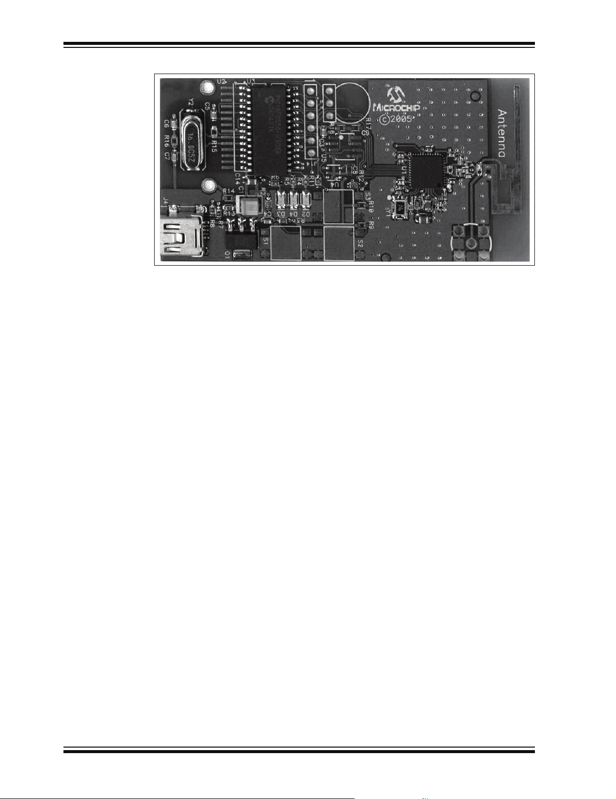
The ZENA Wireless Network Analyzer board, seen in Figure 1-1, combines the
PIC18LF2550 for full-speed, USB support with an IEEE 802.15.4 transceiver.
© 2006 Microchip Technology Inc. DS51606A-page 7
Page 12
ZENA™ Wireless Network Analyzer User’s Guide
FIGURE 1-1: ZENA™ WIRELESS NETWORK ANALYZER BOARD
The ZENA Wireless Network Analyzer uses a USB mini-B cable to connect to the PC.
The ZENA analyzer is powered by the USB bus. A PCB trace antenna receives the
packets on the specified channel and sends the information over USB to the PC
computer using the HID standard class.
DS51606A-page 8 © 2006 Microchip Technology Inc.
Page 13
Chapter 2. Getting Started
2.1 INTRODUCTION
This chapter describes how to install the ZENA Wireless Network Analyzer software.
2.2 INSTALLING ZENA SOFTWARE
Since the ZENA software can be used independently of the hardware, it is available
from multiple sources, including the ZENA Wireless Network Analyzer CD-ROM and
the installation for source files of AN965, “Microchip Stack for the ZigBee
The version shipped with AN965, “Microchip Stack for the ZigBee
version, which provides Stack configuration and packet playback capability, but does
not allow real-time network monitoring with the ZENA Wireless Network Analyzer
hardware. The full version is shipped with the ZENA Wireless Network Analyzer board.
If you are installing the software from the ZENA Wireless Network Analyzer CD-ROM,
insert the CD-ROM into your computer’s CD-ROM drive. If the installation program
does not start automatically, browse to the CD ROM directory and execute the
ZENAvn.nn.exe program, where n.nn is the version number of the ZENA software.
Follow the on-screen directions to install the ZENA software.
If you have installed the source code for one of the Microchip supported IEEE 802.15.4
protocols, the demo version of ZENA software is installed automatically in the root
directory of the application source code. The demo version of ZENA software allows
access to the Stack configuration and message playback features, but it will not
communicate with the ZENA Wireless Network Analyzer hardware.
The ZENA Wireless Network Analyzer license agreement is presented. Read the
agreement, then click I Accept to continue.
The ZENA Wireless Network Analyzer Readme file contains important information
about the most recent release of the ZENA Wireless Network Analyzer, such as new
features and known issues. The Readme file will change with each release.
Once the ZENA software is installed, use the desktop icon or Start Menu item to launch
the ZENA software. The introductory screen appears as follows.
ZENA™ WIRELESS NETWORK
ANALYZER USER’S GUIDE
™ Protocol”.
™ Protocol” is a demo
FIGURE 2-1: ZENA™ SOFTWARE MAIN WINDOW
© 2006 Microchip Technology Inc. DS51606A-page 9
Page 14

ZENA™ Wireless Network Analyzer User’s Guide
NOTES:
DS51606A-page 10 © 2006 Microchip Technology Inc.
Page 15

ZENA™ WIRELESS NETWORK
ANALYZER USER’S GUIDE
Chapter 3. ZigBee™ Protocol Tools
3.1 INTRODUCTION
This chapter describes how to use the ZigBee™ protocol tools provided by the ZENA
Wireless Network Analyzer. Both basic and advance monitoring techniques are
demonstrated.
3.2 MICROCHIP STACK CONFIGURATION TOOL
Microchip provides a freely available Stack as part of application note, AN965,
“Microchip Stack for the ZigBee™ Protocol”. The application note and source code are
available for download from the Microchip web site (www.microchip.com). After you
have reviewed the application note and studied the demonstration projects, you will be
ready to start your own ZigBee protocol application.
The ZENA analyzer will greatly assist you with configuring the Microchip Stack by automatically generating a portion of the source code for your ZigBee protocol application.
Be sure to refer to AN965, “Microchip Stack for the ZigBee™ Protocol” for details about
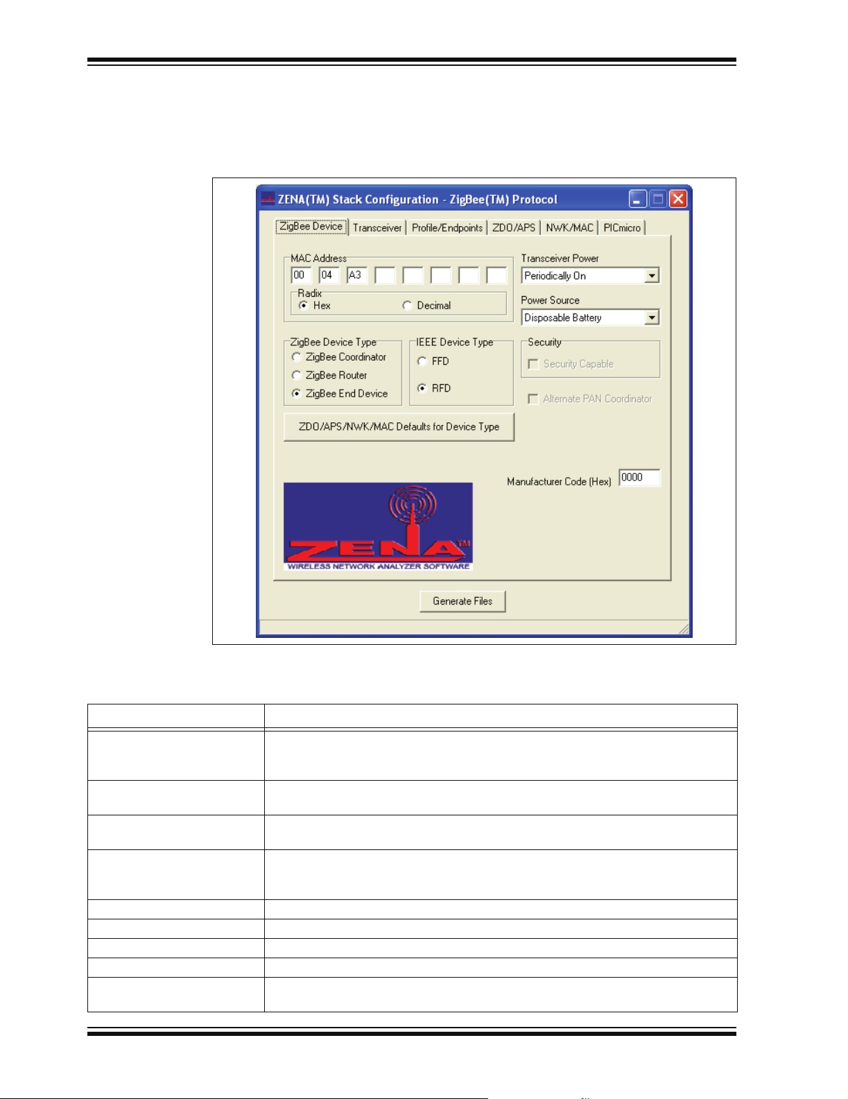
each ZigBee protocol configuration option. Select ZigBee™ Tools>Stack Configuration
from the main ZENA™ Software Stack Configuration window. The ZENA™ Software
Stack Configuration – ZigBee™ Protocol window will be displayed. Using the tabbed
dialog, you can select all of the options required for your ZigBee protocol application.
ZENA software will automatically enable and disable certain options depending on the
selections you have made.
© 2006 Microchip Technology Inc. DS51606A-page 11
Page 16
ZENA™ Wireless Network Analyzer User’s Guide
3.2.1 Specifying ZigBee Protocol Device Information
Select the ZigBee Device tab.
FIGURE 3-1: ZENA™ SOFTWARE STACK CONFIGURATION WINDOW,
ZigBee™ DEVICE TAB
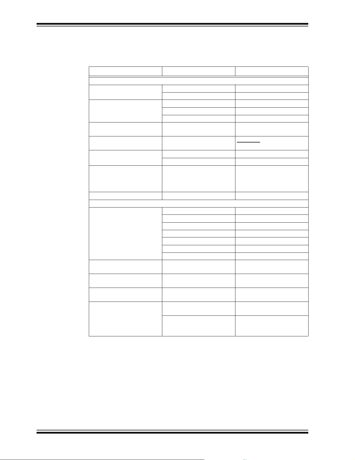
Using this window, you can configure the following items:
TABLE 3-1: ZigBee™ PROTOCOL DEVICE CONFIGURATION SELECTION
Configuration Option Description
MAC Address Each and every ZigBee protocol device must have its own, unique MAC address.
The Microchip OUI is provided as a default for development purposes only. Please
see AN965, “Microchip Stack for the ZigBee™ Protocol” for additional information.
ZigBee Device Type ZigBee protocol defines three different types of devices. Select the device type of
your application.
IEEE Device Type Some ZigBee protocol devices have the option of selecting the IEEE device type.
Select the appropriate IEEE device type for your application.
ZDO/APS/NWK/MAC
Defaults for Device Type
Transceiver Power Offers transceiver power selection. Selects how the transceiver is powered.
Power Source Offers power source selection. Selects your application’s power source.
Security This option is currently not supported by the Microchip Stack for ZigBee protocol.
Alternate PAN Coordinator This option is currently not supported by the Microchip Stack for ZigBee protocol.
Manufacturer Code (Hex) Each manufacturer of ZigBee protocol devices is assigned a manufacturer code by
DS51606A-page 12 © 2006 Microchip Technology Inc.
When you change the device type, the ZENA™ analyzer will automatically set many
options to their default settings unless you have altered them. If you have altered
them and wish to restore them to their default values, click this button.
the ZigBee Alliance. Enter the four-digit hex value.
Page 17
ZigBee™ Protocol Tools
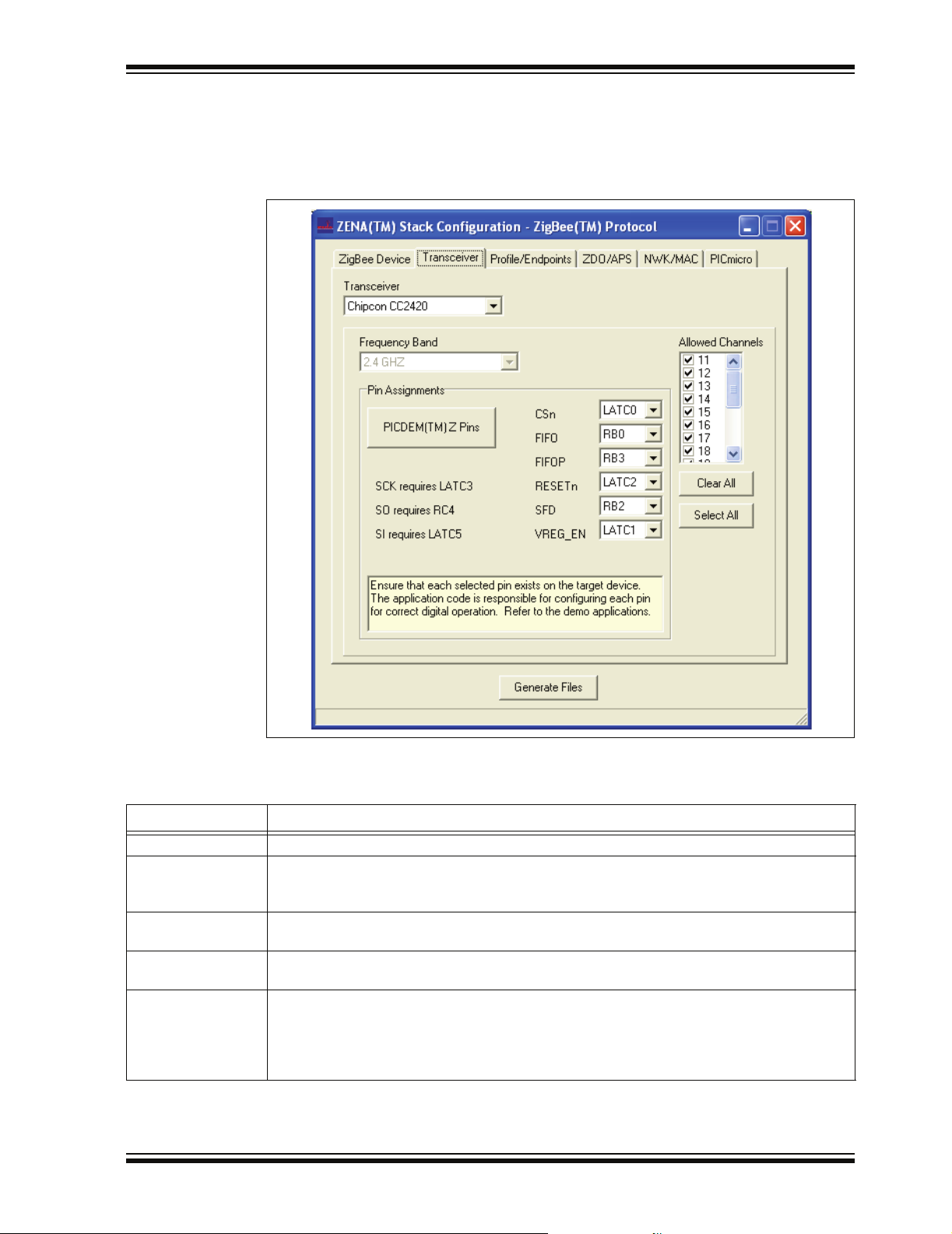
3.2.2 Specifying Transceiver Information
Select the Transceiver tab.
FIGURE 3-2: ZENA™ SOFTWARE STACK CONFIGURATION WINDOW,
TRANSCEIVER TAB
Using this window, you can configure the following items:
TABLE 3-2: ZigBee™ PROTOCOL TRANSCEIVER CONFIGURATION SELECTION
Configuration Option Description
Transceiver Select one of the transceivers supported by the Stack.
Frequency Band This combo box shows the various available frequency bands of the selected transceiver. If
the transceiver supports only one frequency band, that frequency will be displayed and the
combo box will be disabled.
(1)
Pin Assignments
PICDEM™ Z Pins Click this button to restore the pin assignments to the connections used by the PICDEM Z
Allowed Channels This area shows the channels that are supported by the selected frequency band. Selecting
Note 1: Ensure the pin exists on the target device. The application code is responsible for configuring the pin as a
digital input or output as appropriate.
© 2006 Microchip Technology Inc. DS51606A-page 13
This panel shows the required pins for the selected transceiver. The Stack allows you to
change these pin connections to application-specific port pins.
Demonstration Board.
channels here will generate a label that can be used to specify the allowed channels for
network formation and network discovery. Click Clear All to uncheck all channels, and click
Select All to check all channels. Each channel can also be checked or unchecked individually
by clicking on the checkbox that precedes the channel number.
Page 18

ZENA™ Wireless Network Analyzer User’s Guide
3.2.3 Specifying Profile and Endpoint Information
Select the Profile/Endpoints tab.
FIGURE 3-3: ZENA™ SOFTWARE STACK CONFIGURATION WINDOW,
PROFILE/ENDPOINTS TAB
Using this window, you can specify the profile and endpoint structure that your
application is using. See Table 3-3 for configuration options.
CAUTION
It is critical for ZigBee protocol interoperability that this section be accurate.
DS51606A-page 14 © 2006 Microchip Technology Inc.
Page 19

ZigBee™ Protocol Tools
TABLE 3-3: ZigBee™ PROTOCOL PROFILE/ENDPOINTS CONFIGURATION SELECTION
Configuration Option Description
Profile Header File Click the Browse button to browse to and select the header file for the application’s
profile. This file has profile information in a specific format which the ZENA™
analyzer uses to configure many items, including:
- Profile name
- The list of devices supported by the profile
- Allowable input and output clusters
- Range checking for various parameters on other tabs
(1)
Device
Endpoints
(2)
Select the profile device that describes the application.
To define an endpoint:
Enter the endpoint’s numerical value (1-240) in the “Endpoint” edit box. In the
“Endpoint Name” edit box, enter a valid C language label for that endpoint.
Check all the input and output clusters that are supported by that endpoint
under “Input Clusters” and “Output Clusters”.
Click Save Endpoint to save the endpoint. The endpoint number will be added
to the “Endpoints” list box.
To define another endpoint:
Click on “(New)” in the “Endpoints” list box. All the endpoint information will be
cleared. Enter the new endpoint’s information and click Save Endpoint.
To view a previously defined endpoint:
Click on the endpoint number in the “Endpoints” list box.
To remove a specified endpoint:
Click on the endpoint number in the “Endpoints” list box and click Remove
Endpoint.
Note 1: The ZENA analyzer does not confirm that all mandatory clusters are supported for the selected device.
2: Be sure to click Save Endpoint when you are finished defining an endpoint. If the endpoint information
has been entered but not saved, the endpoint will not be included in the generated output files.
© 2006 Microchip Technology Inc. DS51606A-page 15
Page 20

ZENA™ Wireless Network Analyzer User’s Guide
FIGURE 3-4: ENDPOINT SPECIFICATION
DS51606A-page 16 © 2006 Microchip Technology Inc.
Page 21

ZigBee™ Protocol Tools
3.2.4 Specifying ZDO and APS Layer Information
Click on the ZDO/APS tab.
FIGURE 3-5: ZENA™ SOFTWARE STACK CONFIGURATION WINDOW,
ZDO/APS TAB
This tab is used to configure the ZDO (ZigBee Device Object) and APS (Application
Sub-Support) stack layers. Many options on this tab are enabled or disabled based on
the “ZigBee Device Type” specified on the ZigBee Device tab.
Many of these options have a direct correlation to the amount of RAM or nonvolatile
memory required by the application. To view the associated cost in the status bar at the
bottom of the window, hold the mouse cursor over the appropriate edit box. This feature
only functions if the edit box is enabled. See Table 3-4 and Table 3-5 for ZDO and APS
option selections.
TABLE 3-4: ZigBee™ PROTOCOL ZDO CONFIGURATION SELECTION
Configuration Option Description
Include Optional Service
Discovery Requests
Include Optional Node
Management Services
Support End Device Binding This function is available only on ZigBee protocol coordinators. If checked, enter the
If checked, the application will support the optional ZDO service discovery requests.
This feature is not yet supported by the Microchip Stack.
If checked, the application will support the optional ZDO node management services.
This feature is not yet supported by the Microchip Stack
“End Device Bind Timeout (seconds)” in seconds.
© 2006 Microchip Technology Inc. DS51606A-page 17
Page 22

ZENA™ Wireless Network Analyzer User’s Guide
TABLE 3-5: ZigBee™ PROTOCOL APS CONFIGURATION SELECTION
Configuration Option Description
Max Frames From APL Layer Each frame sent down from the Application layer must be buffered for retransmission
on failure and for reporting back transmission confirmation status. Enter the number
of frames that can be in the process of transmitting at the same time.
Max APS ACK Frames
Generated
Max APS Addresses ZigBee protocol allows the Application layer to specify a message destination using
Binding Support
Note 1: Binding support is required for ZigBee protocol coordinators.
(1)
If messages are received from other nodes with APS-level Acknowledgement
requested, the APS layer will automatically transmit the Acknowledge; but space is
still required in the confirmation queue. Enter the number of APS-level
Acknowledges your application is expected to be in the process of transmitting at the
same time.
a node’s 64-bit MAC address, rather than the 16-bit network address. If a 64-bit MAC
address is specified, the APS layer searches an application maintained table for the
corresponding 16-bit network address. Enter the size of that table in this field. If the
Application layer will use only 16-bit network addresses to send messages, or the
application is an IEEE Reduced Function Device, this value can be set to ‘0’.
If the device will support bindings, check this box and enter the “Binding Table Size”.
If a device supports bindings, it must be able to buffer all incoming indirect messages
for retransmission. Enter the number of indirect messages the application is
expected to handle concurrently in the “Max Buffered Indirect Messages” edit box.
DS51606A-page 18 © 2006 Microchip Technology Inc.
Page 23
ZigBee™ Protocol Tools
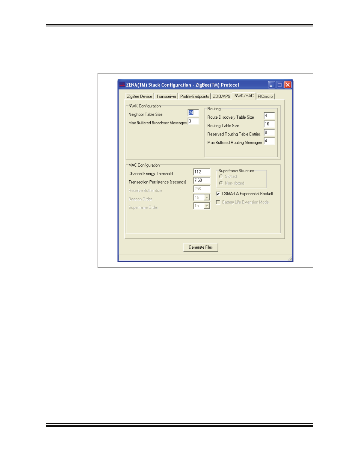
3.2.5 Specifying NWK and MAC Layer Information
Click on the NWK/MAC tab.
FIGURE 3-6: ZENA™ SOFTWARE STACK CONFIGURATION WINDOW,
NWK/MAC TAB
This tab is used to configure the NWK (Network) and MAC (Medium Access Controller)
Stack layers. Many options on this tab are enabled or disabled based on the “ZigBee
Device Type” specified on the ZigBee Device tab.
Many of these options have direct correlation to the amount of RAM or nonvolatile
memory required by the application. To view the associated cost in the status bar at the
bottom of the window, hold the mouse cursor over the appropriate edit box. This feature
only functions if the edit box is enabled. See Table 3-6 and Table 3-7 for NWK and MAC
option selections.
© 2006 Microchip Technology Inc. DS51606A-page 19
Page 24

ZENA™ Wireless Network Analyzer User’s Guide
TABLE 3-6: ZigBee™ PROTOCOL NWK CONFIGURATION SELECTION
Configuration Option Description
Neighbor Table Size
(1)
Max Buffered Broadcast
Messages
Route Discovery Table Size
Routing Table Size
Reserved Routing Table
(1)
Entries
(1)
Max Buffered Routing
Messages
Note 1: The minimum size of this item is specified in the selected profile. See Section 3.2.3 “Specifying Profile
and Endpoint Information”.
TABLE 3-7: ZigBee™ PROTOCOL MAC CONFIGURATION SELECTION
Configuration Option Description
All ZigBee protocol devices contain a neighbor table where they store information
about other nodes in the network.
When a ZigBee protocol device initiates or receives a broadcast message, it must
periodically retransmit that message until it hears all of its Full Function Device
neighbors retransmit the message or the message times out. Enter the number of
broadcast messages that the application is expected to process concurrently.
(1)
If the device supports routing, it must have a route discovery table.
If the device supports routing, it must have a routing table.
If the device supports routing, it must reserve some of the routing table entries for
route repair.
If the device supports routing, it must be able to buffer messages while awaiting
route discovery. Enter the number of messages that can be concurrently buffered
awaiting route discovery.
Channel Energy Threshold This option is available for ZigBee protocol coordinators only. Enter the maximum
amount of energy allowable for a channel to be selected for a new network.
Minimum Join LQI This option is only available for devices other than ZigBee protocol coordinators.
Enter the minimum link quality from a received beacon for that device to be selected
as a potential place to join the network.
Transaction Persistence
(seconds)
This option is available for devices with children whose receivers are off when the
device is Idle and must buffer messages for those children until the children request
them. Enter the amount of time in seconds that messages must be buffered before
they can be discarded.
Receive Buffer Size As bytes are received from the transceiver, they are buffered until an entire message
is received and the application is finished processing the previous message. Enter
the size of this buffer.
Beacon Order
Superframe Order
(1)
(1)
Superframe Structure
(1)
This value is fixed for non-beacon networks.
This value is fixed for non-beacon networks.
Only non-beacon networks are supported; therefore, the superframe structure is
non-slotted.
CSMA-CA Exponential
Check this box to use the IEEE exponential backoff.
Backoff
Battery Life Extension
(1)
Mode
This feature is only used in beacon networks.
Note 1: The Microchip Stack for ZigBee protocol currently supports only non-beacon networks.
DS51606A-page 20 © 2006 Microchip Technology Inc.
Page 25

ZigBee™ Protocol Tools
3.2.6 Specifying PICmicro MCU Information
Click on the PICmicro tab.
FIGURE 3-7: ZENA™ SOFTWARE STACK CONFIGURATION WINDOW,
PICmicro
®
MCU TAB
This tab is used to configure basic PICmicro MCU options (see Table 3-8).
TABLE 3-8: ZigBee™ PROTOCOL STACK CONFIGURATION SELECTION
Configuration Option Description
Target Device Select the PICmicro
is not available, select a similar device and refer to AN965, “Microchip Stack for the
ZigBee™ Protocol” for information on modifying the linker script for the target device.
Clock Frequency (Hz)
UART Baud Rate If you are using the UART of the target device and you are using the interface code
Heap Size (banks) Specify the number of banks of heap space required by the application. Refer to
Stack Size (banks) Specify the number of banks required for the C software Stack. Refer to AN965,
Build Target Select whether you want the linker script generated for a debug environment using
Note 1:
The PICDEM™ Z Demonstration Board has a clock frequency of 16 MHz (16000000 Hz).
(1)
Specify the input clock frequency to the PICmicro MCU in Hertz. It is important that
this value be accurate, as all internal ZigBee protocol timing will be based off of this
value.
provided in AN965, “Microchip Stack for the ZigBee™ Protocol”, specify the UART
baud rate. If your application does not use the UART, this value is irrelevant.
AN965, “Microchip Stack for the ZigBee™ Protocol” for information on setting the
heap size.
“Microchip Stack for the ZigBee™ Protocol” for information on setting the Stack size.
®
MPLAB
ICD 2 or for a production build.
®
MCU device used by the target application. If the exact device
© 2006 Microchip Technology Inc. DS51606A-page 21
Page 26

ZENA™ Wireless Network Analyzer User’s Guide
3.2.7 Generating the Configuration Files
When all of the options on all of the tabs are set appropriately, generate the Stack
configuration files by clicking Generate Files. The ZENA Wireless Network Analyzer
will first perform a validity check to ensure that all required fields have appropriate
values and all profile-specific ranges are met. If no endpoints are specified, the ZENA
analyzer will generate a warning, but will still generate the output files.
Note: Many options, including endpoint specification, affect multiple output files.
Therefore, it is recommended not to mix and match files from different
ZENA analyzer sessions.
If the validity check passes, ZENA analyzer will prompt for an output directory for the
configuration files. These files are:
• zigbee.def – Provides basic definitions for Stack configuration.
• myZigBee.c – Provides all ROM initialization for the Stack, including
ZigBee protocol device descriptors.
• zLink.lkr – Project linker script.
Each of these files has a time and date stamp included in the file. Refer to AN965,
“Microchip Stack for the ZigBee™ Protocol” for more information about these files.
DS51606A-page 22 © 2006 Microchip Technology Inc.
Page 27

3.3 BASIC NETWORK MONITORING
The ZENA Wireless Network Analyzer hardware and software provide a powerful
network monitoring tool for use from development through installation.
Connect the ZENA Wireless Network Analyzer hardware to the PC using the supplied
USB mini-B cable. From the ZENA Software Main window, select
ZigBee™ Tools>Network Monitor
FIGURE 3-8: ZigBee™ PROTOCOL NETWORK MONITOR WINDOW
ZigBee™ Protocol Tools
. The following window will open:
A blank Packet Sniffer window for displaying network messages will also open. If this
window is closed, it can be reopened, either by clicking on the Network Messages
button, or by selecting the View>Network Messages
menu option.
The ZigBee™ Network Monitor window can be used to start and stop real-time network
analysis, save and load data, and configure the display of the messages.
3.3.1 Real-Time Network Monitoring
Before initiating real-time monitoring, set the following options on the ZigBee™
Network Monitor window:
TABLE 3-9: REAL-TIME NETWORK MONITORING CONFIGURATION SELECTION
Configuration Option Description
Real-Time Display Check this box to display on-air messages that are received by the Network Analyzer hardware.
Channel Select the desired channel to monitor. Note that if your application specifies more than one
allowable channel to form or join a network, you may have to try multiple channels to find the
network. This selection can be changed only while real-time monitoring is stopped.
Clear Messages
on Start
Ignore Invalid Packets If you want packets with invalid checksums to be ignored, check this box. If you want all
Auto Scroll
Note 1: If “Auto Scroll” is checked, system response may slow. “Auto Scroll” can be disabled while real-time
(1)
monitoring is in progress.
If you want all previously displayed messages to be erased when you start monitoring, check
this box. If you want the messages to be retained, uncheck this box.
network traffic and noise to be displayed, uncheck this box.
If you want the Packet Sniffer window to automatically scroll, such that the newest message
always appears on the bottom of the Packet Sniffer window, check this box.
Click the Play button or select the Operation>Start Sniffing/Playback
menu option to
begin real-time monitoring. The received messages are then displayed on the Packet
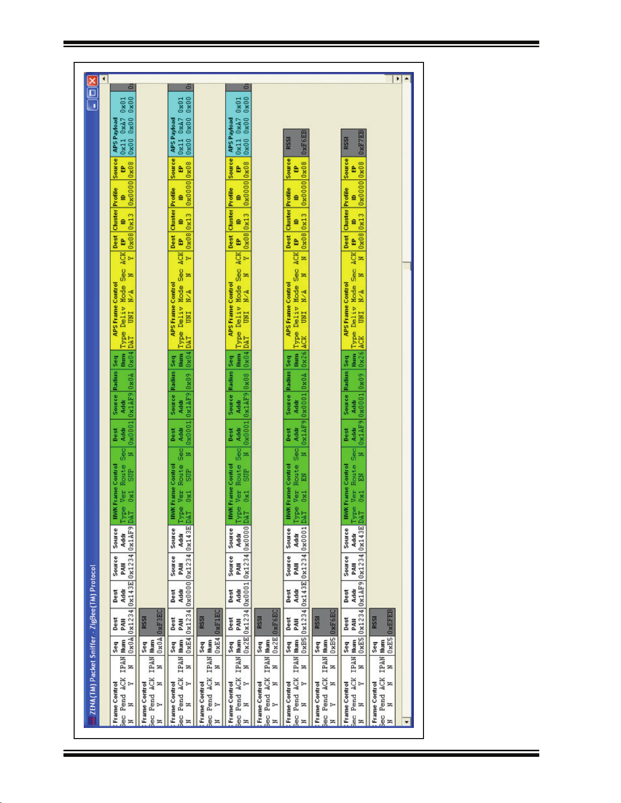
Sniffer window. Figure 3-9 shows a typical sequence of a new node joining a ZigBee
protocol network.
© 2006 Microchip Technology Inc. DS51606A-page 23
Page 28

ZENA™ Wireless Network Analyzer User’s Guide
FIGURE 3-9: ASSOCIATION REQUEST AND RESPONSE
DS51606A-page 24 © 2006 Microchip Technology Inc.
Page 29

ZigBee™ Protocol Tools
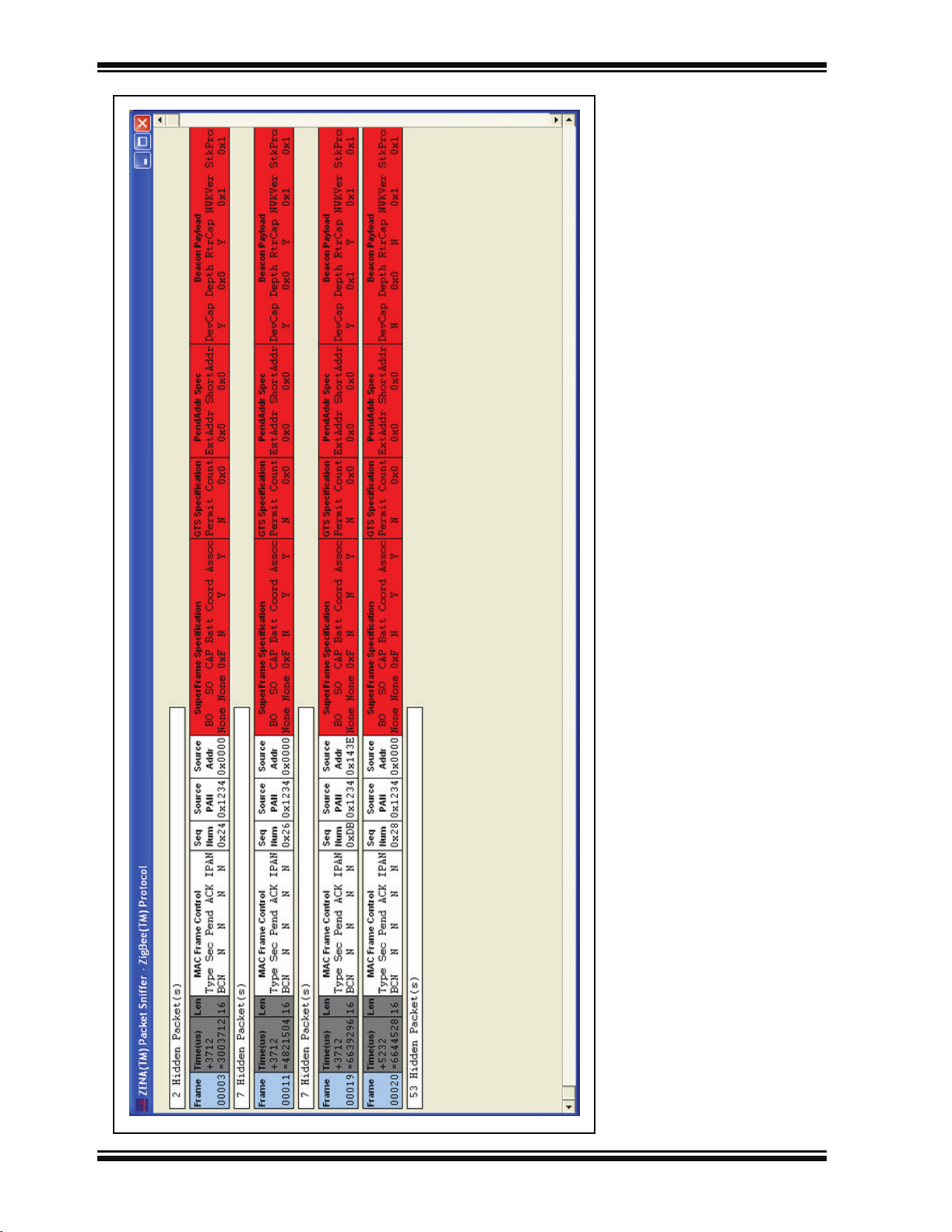
The various portions of the message are color coded for clarity.
TABLE 3-10: PACKET SNIFFER COLOR CODING
Field Color
MAC Header White
MAC Commands and Beacons Red
NWK Header Lime
NWK Commands Fuchsia
APS Header Yellow
APS Payload/Decoding Aqua
Unknown Olive
Figure 3-10 shows a message being routed from the originator to the final destination
and an APS-level Acknowledge being routed back. Note that by using the ZENA
analyzer, we can see that the first message is being routed along the network tree,
while the Acknowledge is being routing more directly.
© 2006 Microchip Technology Inc. DS51606A-page 25
Page 30
ZENA™ Wireless Network Analyzer User’s Guide
FIGURE 3-10: APPLICATION MESSAGE WITH APS-LEVEL ACKNOWLEDGE
DS51606A-page 26 © 2006 Microchip Technology Inc.
Page 31

ZigBee™ Protocol Tools
Each message can contain a great deal of information, making it difficult to view on the
screen. The Packet Sniffer window can be scrolled, but the ZENA analyzer also offers
three different levels of viewing the MAC, NWK and APS-level information. Each layer
can be configured separately on the Network Monitor window by adjusting the
“Verboseness Level”; there are three levels offered (see Table 3-11).
TABLE 3-11: ZigBee™ PROTOCOL VERBOSENESS LEVEL CONFIGURATION SELECTION
Configuration Option Description
Verbose Headers for each field are provided with a description of the corresponding value
below the header. Figure 3-10 shows all layers at the “Verbose” setting.
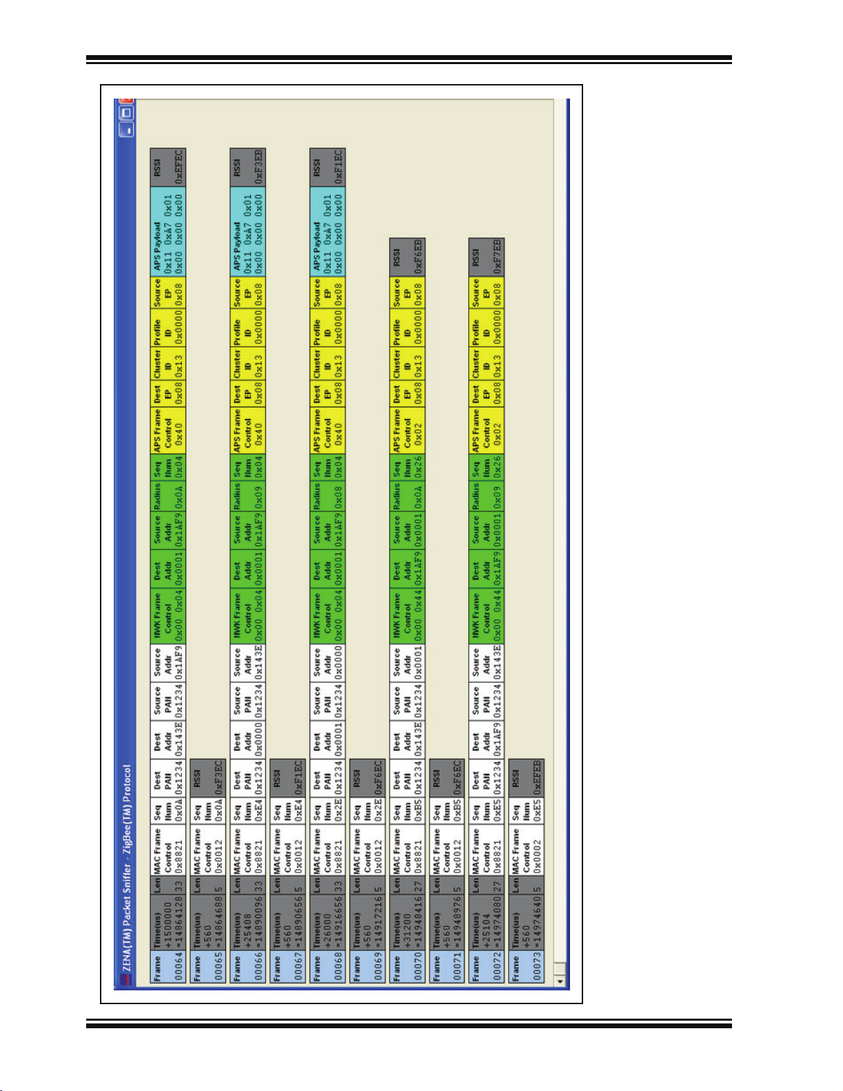
Numeric Headers for each field are provided with the numeric value of that field below the
header. Refer to Figure 3-11.
Condensed No field headers are provided. All bytes of the field are represented numerically with
the Least Significant Byte first. Refer to Figure 3-12.
© 2006 Microchip Technology Inc. DS51606A-page 27
Page 32
ZENA™ Wireless Network Analyzer User’s Guide
FIGURE 3-11: APPLICATION MESSAGE WITH NUMERIC DISPLAY
DS51606A-page 28 © 2006 Microchip Technology Inc.
Page 33

ZigBee™ Protocol Tools
FIGURE 3-12: APPLICATION MESSAGE WITH CONDENSED DISPLAY
© 2006 Microchip Technology Inc. DS51606A-page 29
Page 34

ZENA™ Wireless Network Analyzer User’s Guide
The data can be viewed and analyzed to some degree while real-time monitoring is in
progress. For more advanced analysis, real-time monitoring must be halted by clicking
the Stop button or selecting the Operation>Stop Sniffing/Playback
To save the data for analysis at a later time, click the Save button or select the
File>Save
menu option.
3.3.1.1 TIME-STAMPS
The displayed time-stamp is the time from the end of the previous message until the
end of the current message. The time-stamp is displayed in micro seconds, and can
represent up to 71 minutes before rolling over.
3.3.2 Analyzing Previously Captured Data
When real-time network monitoring is stopped, the ZENA Wireless Network Analyzer
can be used to perform further analysis of the captured data. If real-time monitoring is
in progress, halt it by clicking the Stop button or by selecting the
O
peration>Start Sniffing/Playback menu option. To analyze previously captured data,
click Open or select File>Open
Uncheck the “Real Time Display” checkbox to enable the analysis capabilities.
3.3.2.1 PACKET PLAYBACK
and select the desired data file.
menu option.
Captured data can be played back as if it were being received in real time. Playback
can begin at any point in the data. To select the first packet to play back, click on the
desired packet in the Packet Sniffer window. The selected packet will then be outlined
in red.
Note: If playback is currently in progress (the Start button is disabled and the
Stop button is enabled), a packet cannot be selected with a mouse click.
Select the desired playback speed using the “Speed” combo box. Available options
are:
TABLE 3-12: ZigBee™ PROTOCOL PACKET PLAYBACK SELECTION
Packet Option Description
x0.01 Packets are played back approximately 100 times faster than they were received.
x0.1 Packets are played back approximately 10 times faster than they were received.
x1 Packets are played back at approximately the same rate as they were received.
x10 Packets are played back approximately 10 times slower than they were received.
x100 Packets are played back approximately 100 times slower than they were received.
2 sec Packets are played back at 2-second intervals between packets.
Instant Packets are played back as quickly as possible.
Manual Packet playback is controlled by the up and down arrow keys.
Packet playback is especially useful when using the filter option and performing more
advanced network analysis.
DS51606A-page 30 © 2006 Microchip Technology Inc.
Page 35

ZigBee™ Protocol Tools
3.3.2.2 USING THE PACKET FILTER
Click the Filter button or select the Tools>Filter
Monitor window and display the filter options.
FIGURE 3-13: NETWORK MONITOR WINDOW WITH FILTER
menu option to enlarge the Network
The filter is useful for displaying only selected packets in the Packet Sniffer window. For
example, suppose we wish to see all beacons generated by our network. Set up the
filter as follows:
1. Clear all “MAC Commands” checkboxes except “MAC Beacon”.
2. Clear all “NWK Commands” checkboxes.
3. Check all “Source Address” and “Destination Address” entries.
4. Select the “AND” option.
5. Click Apply Filter.
The Packet Sniffer window will then display all beacon packets and hide all others.
Refer to Figure 3-14.
© 2006 Microchip Technology Inc. DS51606A-page 31
Page 36
ZENA™ Wireless Network Analyzer User’s Guide
FIGURE 3-14: FILTERED BEACONS
DS51606A-page 32 © 2006 Microchip Technology Inc.
Page 37

ZigBee™ Protocol Tools
Note: If the “Source Address” and “Destination Address” areas are empty and are
needed for your desired filter, replay the network formation portion of the
data. If you will be working with a network that maintains the same structure, you may want to save a captured data file that contains the network
formation for populating these fields.
To redisplay all messages, click Clear Filter.
To close the filter and return the Network Monitor window to its original size, click Close
Filter.
3.3.2.3 HIDING AND UNHIDING PACKETS
Packets in the Packet Sniffer window can be hidden in two ways:
• Using the filter function as described above
• Right clicking on a packet and selecting Hide
Note: Multiple packets can be selected for hiding by holding down the control key
while clicking each desired packet. A range of packets can be selected by
clicking on the first packet of the range, then holding down the shift key
while clicking on the last packet of the range. Each selected packet will be
outlined in red. When all desired packets have been selected, right click
and select Hide
to hide all selected packets.
from the pop-up menu
The hidden packets can be redisplayed by right clicking on the appropriate X Hidden
Packet(s) box in the Packet Sniffer window and clicking UnHide
.
© 2006 Microchip Technology Inc. DS51606A-page 33
Page 38
ZENA™ Wireless Network Analyzer User’s Guide
3.4 ADVANCED NETWORK MONITORING AND ANALYSIS
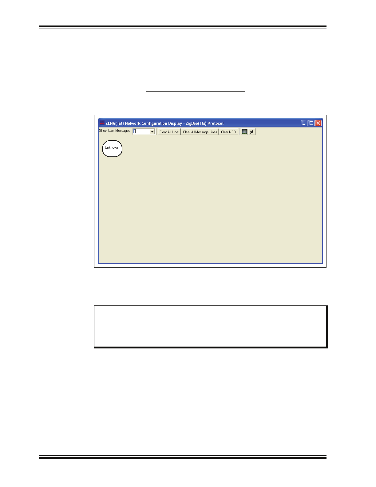
3.4.1 Network Configuration Display Window
The ZENA Wireless Network Analyzer provides an extra level of network monitoring
and analysis with the Network Configuration Display (NCD) window. Open the Network
Configuration Display window by clicking the Network Configuration Display button
or by selecting the View>Network Configuration Display
Monitor window.
FIGURE 3-15: NETWORK CONFIGURATION DISPLAY WINDOW
menu option on the Network
The NCD window can be used during both real-time network monitoring and packet
playback. If the “Clear NCD on Start” checkbox on the Network Monitor window is
checked, then the NCD window will be cleared when real-time monitoring is started. If
you want the nodes to be retained, uncheck this box.
Note: Due to heavy system loading during real-time monitoring, the NCD window
may not update properly during real-time monitoring, particularly if there is
a lot of network traffic and if “Auto Scroll” is enabled. For best results,
disable “Auto Scroll” if network traffic is heavy. The NCD window will update
properly during packet playback.
DS51606A-page 34 © 2006 Microchip Technology Inc.
Page 39

ZigBee™ Protocol Tools
When the ZENA analyzer receives a message from a device, it creates a node on the
NCD window. The label for the node will be its 64-bit MAC address. To see the node’s
PAN ID and 16-bit network address, hold the mouse cursor over the node. If the ZENA
analyzer monitors network creation, it can also color code the nodes according to
device type.
TABLE 3-13: Node Colors
Node Type Color
ZigBee™ Protocol Coordinator Aqua
ZigBee Protocol Router Fuchsia
FFD End Device Lime
RDF End Device Yellow
Unknown White
When a message travels from one device to another, the NCD window will display a
line from the source node to the destination node. If a device transmits a broadcast
message, the NCD window will display a circle around the source node.
Note: Some messages, such as MAC Acknowledges, do not contain any address
information. These messages are shown originating from the Unknown
node.
Nodes can be hidden by right clicking on the node and selecting Hide
. A new node,
named “Hidden”, will be created and all lines that would normally be drawn to the
hidden nodes will be drawn to that node. To unhide all hidden nodes, right click on the
“Hidden” node and select Unhide All
.
When a device joins the network, the parent-child relationship of that device is shown
by a silver line between the two devices. See Table 3-14 for NCD window controls.
TABLE 3-14: ZigBee™ PROTOCOL NCD CONFIGURATION SELECTION
Control Option Description
Show Last Messages This combo box allows you to select how many message lines are displayed. When
a new message line is drawn, the oldest line is removed. Several predefined options
are available, or you may enter your own value. The silver network association lines
are not affected by this setting.
Clear All Lines Click this button to clear all message and network association lines. The nodes
themselves are unaffected.
Clear All Message Lines Click this button to clear all message lines. The network association lines and the
nodes themselves are unaffected.
Clear NCD Click this button to clear all message lines, all network association lines and all
nodes.
Select Bitmap Click this button to load a background image. This is described in more detail in
Section 3.4.4 “Customizing the Network Configuration Display Window”.
Clear Background Click this button to remove the background image.
© 2006 Microchip Technology Inc. DS51606A-page 35
Page 40

ZENA™ Wireless Network Analyzer User’s Guide
3.4.2 Viewing Network Formation
The following sequence of figures shows how network formation appears on the NCD
window.
First, the ZigBee protocol coordinator sends a beacon request.
FIGURE 3-16: NCD BEACON REQUEST
Since there are no nodes on this channel, no beacons are received, and the ZigBee
protocol coordinator forms a network.
Next, a ZigBee protocol router tries to find a network to join. It also emits a beacon
request, which looks just like Figure 3-16, since the beacon request contains no source
address information. Now, the ZigBee protocol coordinator responds with a beacon.
DS51606A-page 36 © 2006 Microchip Technology Inc.
Page 41
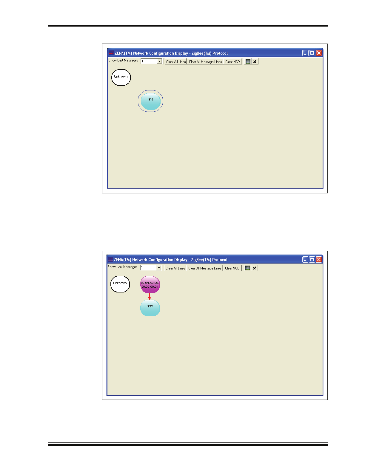
FIGURE 3-17: NCD BEACON
ZigBee™ Protocol Tools
Note that the ZENA analyzer can tell from the beacon that this device is a ZigBee
protocol coordinator, but it does not yet know its MAC address.
The ZigBee protocol router will now try to join the network by sending an Association
Request. The ZENA analyzer can tell from the Association Request what type of device
is trying to join the network.
FIGURE 3-18: NCD ASSOCIATION REQUEST
© 2006 Microchip Technology Inc. DS51606A-page 37
Page 42

ZENA™ Wireless Network Analyzer User’s Guide
After a short time, the ZigBee protocol router will send a Data Request, asking for the
Association Response. The ZigBee protocol coordinator will respond by sending the
Association Response.
FIGURE 3-19: NCD ASSOCIATION RESPONSE
Now the device has joined the network. This relationship can be seen by clicking Clear
All Message Lines to display only the network association lines.
FIGURE 3-20: TWO-DEVICE NETWORK
DS51606A-page 38 © 2006 Microchip Technology Inc.
Page 43
ZigBee™ Protocol Tools
Figure 3-21 shows the NCD window after the creation of a four-device network.
FIGURE 3-21: FOUR-DEVICE NETWORK
Note: If you will be working with a network that maintains the same structure, you
may want to save a captured data file that contains the network formation.
You can play back this file to establish the devices on the network, and then
play back the various data files containing the network traffic you wish to
monitor.
© 2006 Microchip Technology Inc. DS51606A-page 39
Page 44

ZENA™ Wireless Network Analyzer User’s Guide
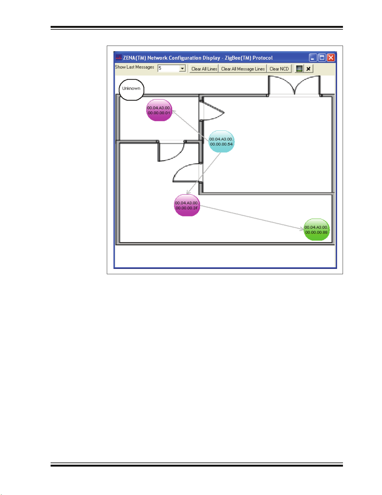
3.4.3 Viewing Network Traffic
After the network above was created, one of the devices attempted to send a message
to another device. The path that the message followed is shown in Figure 3-22.
FIGURE 3-22: NCD MESSAGE PATH
The NCD window shows how the message went from device 00.04.A3.00.00.00.00.88
to device 00.04.A3.00.00.00.00.01, traveling through two other nodes.
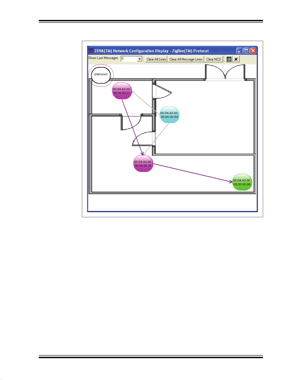
This particular message requested an APS Acknowledge. Figure 3-23 shows the path
of the APS Acknowledge. The ZENA analyzer illustrates that the APS Acknowledge
followed a different route than the original message.
FIGURE 3-23: NCD APS ACKNOWLEDGE PATH
DS51606A-page 40 © 2006 Microchip Technology Inc.
Page 45
ZigBee™ Protocol Tools
3.4.4 Customizing the Network Configuration Display Window
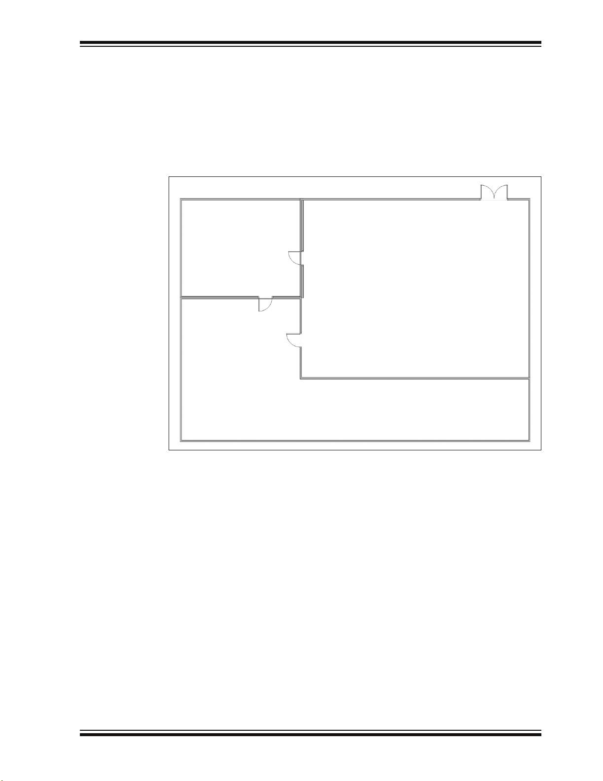
When analyzing network traffic, it is often helpful to understand the physical relationship between the devices. The ZENA analyzer allows you to select a bitmap as the
background of the NCD window. The nodes can then be dragged so they match their
physical location.
For example, Microsoft
generate a simple floor plan. The floor plan can then be exported as a bitmap.
FIGURE 3-24: FLOOR PLAN BITMAP
®
Visio® drawing and diagramming software can be used to
Load this floor plan as the NCD background by clicking the Select Bitmap button. The
NCD window can be resized after loading the background to match the proportions of
the bitmap.
© 2006 Microchip Technology Inc. DS51606A-page 41
Page 46

ZENA™ Wireless Network Analyzer User’s Guide
FIGURE 3-25: NCD WINDOW WITH FLOOR PLAN BACKGROUND
When network formation is played back and displayed on the NCD window, the nodes
can be moved to the location on the bitmap that represents their physical location.
DS51606A-page 42 © 2006 Microchip Technology Inc.
Page 47
ZigBee™ Protocol Tools
FIGURE 3-26: FOUR-NODE NETWORK WITH FLOOR PLAN BACKGROUND
Repeating the above example, Figure 3-27 and Figure 3-28 show the application
message and APS Acknowledge as they are routed through the network.
© 2006 Microchip Technology Inc. DS51606A-page 43
Page 48

ZENA™ Wireless Network Analyzer User’s Guide
FIGURE 3-27: MESSAGE PATH WITH FLOOR PLAN BACKGROUND
DS51606A-page 44 © 2006 Microchip Technology Inc.
Page 49
ZigBee™ Protocol Tools
FIGURE 3-28: APS ACKNOWLEDGE PATH WITH FLOOR PLAN
BACKGROUND
© 2006 Microchip Technology Inc. DS51606A-page 45
Page 50

ZENA™ Wireless Network Analyzer User’s Guide
3.4.5 Analyzing Network Traffic
The ZENA Wireless Network Analyzer can provide a great deal of information about
device and network operation. The Packet Sniffer window can be used to ensure that
messages are appearing on the air as expected, and that the messages have the
correct format. The NCD window can be used to ensure the network is formed in the
correct manner.
The ZENA analyzer can show how messages propagate through the network. In the
examples above, we see by using the NCD window that the application message is
routed along the network tree, while the Acknowledge is routed more directly. Using the
Packet Sniffer window, we can determine if the message was sent with routing
suppressed, or if routing was requested but a node in the path did not have routing
capacity.
The ZENA analyzer can also provide insight as to physical barriers that are affecting
the system. In the previous example, we can see that physical barriers are probably
preventing two nodes from talking directly.
With a larger scale network, the ZENA analyzer can also help determine if device layout
needs to be optimized for the system’s required network traffic. If the ZENA analyzer
indicates that a great deal of traffic is being routed through a single device, that device
may be getting overloaded. An alternate arrangement of devices might generate more
balanced network traffic.
3.4.6 Exporting Data
In some cases, it may be necessary to export the raw message data to another tool for
further analysis. To export raw data, select the desired packets in the Packet Display
window, right click on the packets and select Copy To Clipboard
will be exported to the clipboard in ASCII format, each packet on a new line, with a
space after each byte. Approximately 21000 bytes of packet information can be
exported at one time.
. The raw packet data
DS51606A-page 46 © 2006 Microchip Technology Inc.
Page 51

ZENA™ WIRELESS NETWORK
ANALYZER USER’S GUIDE
Index
A
Advanced Network Monitoring ................................. 34
Analyzing Traffic ............................................... 46
Configuration Display Window.......................... 34
Customizing Configuration
Display Window.................................. 41
Viewing Formation............................................ 36
Viewing Traffic .................................................. 40
APS Configuration Selection
Binding Support ................................................ 18
Max APS ACK Frames Generated ................... 18
Max APS Addresses......................................... 18
Max Frames From APL Layer........................... 18
C
Configuration File Generation .................................. 22
Customer Change
Notification Service................................................. 4
Customer Support...................................................... 5
D
Device Configuration Selection
Alternate PAN Coordinator ............................... 12
IEEE Device Type............................................. 12
MAC Address.................................................... 12
Manufacturer Code (Hex) ................................. 12
Power Source ................................................... 12
Security............................................................. 12
Transceiver Power............................................ 12
ZDO/APS/NWK/MAC........................................ 12
ZigBee Device Type ......................................... 12
Documentation
Conventions........................................................ 2
Layout ................................................................. 1
Revision History.................................................. 5
F
Four-Device Network ............................................... 39
I
Installation
License Agreement............................................. 9
Readme file......................................................... 9
ZENA Software ................................................... 9
Internet Address......................................................... 4
K
Kit Contents................................................................ 7
USB mini-B Cable ............................................... 7
ZENA Wireless Network Analyzer ...................... 7
ZENA Wireless Network
Analyzer CD-ROM................................ 7
M
MAC Configuration Selection
Battery Life Extension Mode ............................. 20
Beacon Order.................................................... 20
Channel Energy Threshold ............................... 20
CSMA-CA Exponential Backoff......................... 20
Minimum Join LQI............................................. 20
Receive Buffer Size .......................................... 20
Superframe Order............................................. 20
Superframe Structure........................................ 20
Transaction Persistence (seconds)................... 20
Microchip Internet Web Site ....................................... 4
MPLAB
®
IDE.............................................................. 1
N
NCD APS Acknowledge Path .................................. 40
NCD Association Request........................................ 37
NCD Association Response..................................... 38
NCD Beacon ............................................................ 37
NCD Beacon Request.............................................. 36
NCD Configuration Selection
Clear All Lines................................................... 35
Clear All Message Lines ................................... 35
Clear Background ............................................. 35
Clear NCD......................................................... 35
Select Bitmap.................................................... 35
Show Last Messages........................................ 35
NCD Message Path ................................................. 40
Network Monitoring .................................................. 23
Node Colors ............................................................. 35
NWK and MAC Layer
Specifying ......................................................... 19
NWK Configuration Selection
Max Buffered Broadcast Messages .................. 20
Max Buffered Routing Messages...................... 20
Neighbor Table Size ......................................... 20
Reserved Routing Table Entries ....................... 20
Route Discovery Table Size.............................. 20
Routing Table Size............................................ 20
© 2006 Microchip Technology Inc. DS51606A-page 47
Page 52

ZENA™ Wireless Network Analyzer User’s Guide
P
Packet
Exporting Data .................................................. 46
Filter Use........................................................... 31
Hiding and Unhiding.......................................... 33
Playback ........................................................... 30
Playback Selection
2 sec .......................................................... 30
Instant ........................................................30
Manual ....................................................... 30
x0.01 .......................................................... 30
x0.1 ............................................................ 30
x1 ............................................................... 30
x10 ............................................................. 30
x100 ...........................................................30
Packet Sniffer Color Coding
APS Header ...................................................... 25
APS Payload/Decoding.....................................25
MAC Commands and Beacons......................... 25
MAC Header ..................................................... 25
NWK Commands .............................................. 25
NWK Header..................................................... 25
Unknown ........................................................... 25
PICmicro MCU
Specifying ......................................................... 21
Previously Captured Data
Analyzing .......................................................... 30
Profile and Endpoint
Specifying ......................................................... 14
Profile/Endpoints Configuration Selection
Device ............................................................... 15
Endpoints .......................................................... 15
Profile Header File ............................................ 15
R
Real-Time Network Monitoring................................. 23
Real-Time Network Monitoring
Configuration Selection
Auto-Scroll ........................................................ 23
Channel............................................................. 23
Clear Messages on Start .................................. 23
Ignore Invalid Packets....................................... 23
Real-Time Display............................................. 23
Recommended Reading............................................. 3
AN965 ................................................................. 3
IEEE 802.15.4 Specification ............................... 3
Microchip 8-Bit MCU Solutions ........................... 3
Microchip Stack for the ZigBee™ Protocol ......... 3
PICDEM Z Demonstration Kit User’s Guide........ 3
PICmicro MCU Data Sheets,
Family Reference Manuals ................... 3
Readme for ZENA Wireless
Network Analyzer ................................. 3
ZigBee™ Protocol Specification.......................... 3
S
Stack Configuration Selection
Build Target.......................................................21
Clock Frequency (Hz) .......................................21
Heap Size (banks)............................................. 21
Stack Size (banks) ............................................ 21
Target Device....................................................21
UART Baud Rate ..............................................21
Stack Configuration Tool.......................................... 11
T
Time-Stamps ............................................................ 30
Transceiver
Specifying.......................................................... 13
Transceiver Configuration Selection
Allowed Channels .............................................13
Frequency Band................................................ 13
PICDEM Z Pins .................................................13
Pin Assignments ...............................................13
Transceiver .......................................................13
Two-Device Network ................................................ 38
U
USB mini-B Cable ....................................................23
V
Verboseness Level Configuration Selection
Condensed........................................................ 27
Numeric.............................................................27
Verbose.............................................................27
W
WWW Address ........................................................... 4
Z
ZDO and APS Layer
Specifying.......................................................... 17
ZDO Configuration Selection
Include Optional Node
Management Services........................ 17
Include Optional Service
Discovery Requests............................17
Support End Device Binding ............................. 17
ZENA Analyzer
Overview .............................................................7
ZigBee Protocol Device
Specifying.......................................................... 12
DS51606A-page 48 © 2006 Microchip Technology Inc.
Page 53

NOTES:
Index
© 2006 Microchip Technology Inc. DS51606A-page 49
Page 54

WORLDWIDE SALES AND SERVICE
AMERICAS
Corporate Office
2355 West Chandler Blvd.
Chandler, AZ 85224-6199
Tel: 480-792-7200
Fax: 480-792-7277
Technical Support:
http://support.microchip.com
Web Address:
www.microchip.com
Atlanta
Alpharetta, GA
Tel: 770-640-0034
Fax: 770-640-0307
Boston
Westborough, MA
Tel: 774-760-0087
Fax: 774-760-0088
Chicago
Itasca, IL
Tel: 630-285-0071
Fax: 630-285-0075
Dallas
Addison, TX
Tel: 972-818-7423
Fax: 972-818-2924
Detroit
Farmington Hills, MI
Tel: 248-538-2250
Fax: 248-538-2260
Kokomo
Kokomo, IN
Tel: 765-864-8360
Fax: 765-864-8387
Los Angeles
Mission Viejo, CA
Tel: 949-462-9523
Fax: 949-462-9608
San Jose
Mountain View, CA
Tel: 650-215-1444
Fax: 650-961-0286
Toronto
Mississauga, Ontario,
Canada
Tel: 905-673-0699
Fax: 905-673-6509
ASIA/PACIFIC
Australia - Sydney
Tel: 61-2-9868-6733
Fax: 61-2-9868-6755
China - Beijing
Tel: 86-10-8528-2100
Fax: 86-10-8528-2104
China - Chengdu
Tel: 86-28-8676-6200
Fax: 86-28-8676-6599
China - Fuzhou
Tel: 86-591-8750-3506
Fax: 86-591-8750-3521
China - Hong Kong SAR
Tel: 852-2401-1200
Fax: 852-2401-3431
China - Qingdao
Tel: 86-532-8502-7355
Fax: 86-532-8502-7205
China - Shanghai
Tel: 86-21-5407-5533
Fax: 86-21-5407-5066
China - Shenyang
Tel: 86-24-2334-2829
Fax: 86-24-2334-2393
China - Shenzhen
Tel: 86-755-8203-2660
Fax: 86-755-8203-1760
China - Shunde
Tel: 86-757-2839-5507
Fax: 86-757-2839-5571
China - Wuhan
Tel: 86-27-5980-5300
Fax: 86-27-5980-5118
China - Xian
Tel: 86-29-8833-7250
Fax: 86-29-8833-7256
ASIA/PACIFIC
India - Bangalore
Tel: 91-80-4182-8400
Fax: 91-80-4182-8422
India - New Delhi
Tel: 91-11-5160-8631
Fax: 91-11-5160-8632
India - Pune
Tel: 91-20-2566-1512
Fax: 91-20-2566-1513
Japan - Yokohama
Tel: 81-45-471- 6166
Fax: 81-45-471-6122
Korea - Gumi
Tel: 82-54-473-4301
Fax: 82-54-473-4302
Korea - Seoul
Tel: 82-2-554-7200
Fax: 82-2-558-5932 or
82-2-558-5934
Malaysia - Penang
Tel: 60-4-646-8870
Fax: 60-4-646-5086
Philippines - Manila
Tel: 63-2-634-9065
Fax: 63-2-634-9069
Singapore
Tel: 65-6334-8870
Fax: 65-6334-8850
Taiwan - Hsin Chu
Tel: 886-3-572-9526
Fax: 886-3-572-6459
Taiwan - Kaohsiung
Tel: 886-7-536-4818
Fax: 886-7-536-4803
Taiwan - Taipei
Tel: 886-2-2500-6610
Fax: 886-2-2508-0102
Thailand - Bangkok
Tel: 66-2-694-1351
Fax: 66-2-694-1350
EUROPE
Austria - Wels
Tel: 43-7242-2244-399
Fax: 43-7242-2244-393
Denmark - Copenhagen
Tel: 45-4450-2828
Fax: 45-4485-2829
France - Paris
Tel: 33-1-69-53-63-20
Fax: 33-1-69-30-90-79
Germany - Munich
Tel: 49-89-627-144-0
Fax: 49-89-627-144-44
Italy - Milan
Tel: 39-0331-742611
Fax: 39-0331-466781
Netherlands - Drunen
Tel: 31-416-690399
Fax: 31-416-690340
Spain - Madrid
Tel: 34-91-708-08-90
Fax: 34-91-708-08-91
UK - Wokingham
Tel: 44-118-921-5869
Fax: 44-118-921-5820
02/16/06
DS51606A-page 50 © 2006 Microchip Technology Inc.
 Loading...