

Page 1
DS96DSP0201
P R E L I M I N A R Y
1-1
1
P
RELIMINARY
C
USTOMER
P
ROCUREMENT
S
PECIFICATION
Z89340
1
D
IGITAL
W
AVETABLE
E
NGINE
FEATURES
■
64 High-Speed Audio Processing Units (APUs) or 128
Half-Speed APUs
■
3-D Sound Capability
■
Downloadable Sample Capability
■
8-Channel, 20-Bit Linear PCM Audio Generator
■
Output Sampling Rates up to 50 kHz
■
Supports 16-, 18-, and 20-Bit Serial DACS – Greater
than 96 Db Dynamic Range
■
Supports 16- and 8-Bit Linear PCM Sampling, ADPCM,
and Wavetable Synthesis, Variable Playback Rates for
ADPCM
■
Internal 24-Bit Audio Accumulators
■
Addresses 16M x 16 Sample ROM Directly (No Paging
Necessary)
■
Jumperless Configurable ISA Bus Interface
■
Sound Blaster and OPL3 Register Compatibility,
MPU401 UART Mode Compatible
■
Built-In 64-Channel Bus-Mastering DMA Controller
■
FM Emulation
GENERAL DESCRIPTION
The Z89340 is a high-performance, programmable wavetable engine designed for musical instruments, general
MIDI (Musical Instrument Digital Interface) sound modules,
digital mixing consoles with high-quality PC sound cards,
and computer-controlled multimedia applications.
This device features a 24-bit address bus for
addressing16-bit sample-storage ROM and DRAM (DRAM
refresh controller on-board), a 12x16 two’s-complement
scaler, eight 24-bit accumulators with clipping circuitry, a
2x8x16 interpolator to allow a high resolution of phase angles between input samples, CD-quality sampling rates,
and 64 high-speed audio processing units (APUs) that can
be split into two low-speed APUs that operate at half the
sampling rate, allowing up to 128 notes to play simultaneously. All APUs are independent and can address any
part of data storage at any time.
The Z89340 can operate at output sampling rates up to 50
kHz, and offers eight channels of 16- to 20-bit serial output
data. The microprocessor interface allows full control of
frequency, amplitude, and sample data input to each oscillator. The Z89340 features eight output registers, and their
contents can be sent to DAC or CODEC. Four of these can
be used for quadraphonic output, and have a panning
mechanism called Polar Pan that supports motion in all
four quadrants.
The other four output registers are used internally as effects channels, but can still send their data streams to a
DAC, a second Z89340, or other digital signal processor.
The Z89340 also has eight serial input data registers. In
addition, there are 24 stereo submix register pairs for use
in sending output data from one APU to be used as the input to another.
In particular, the Z89340 is well-suited for 8- and 16-bit linear PCM recording/playback, wave synthesis, Sound
Blaster command set, and ADPCM (IMA/DVI) real-time decompression.
Part Number Speed Package
Z89340 50 MHz 160-Pin QFP
Page 2
Z89340
Digital Wavetable Engine
1-2
P R E L I M I N A R Y
DS96DSP0201
GENERAL DESCRIPTION (Continued)
Figure 1. Z89340 Simplified Functional Block Diagram
ISA
Interface
Sound
Blaster
Registers
FM
Emulation
MIDI
(MPU 401)
Port
IDE
CD-ROM
Interface
Joystick/
Game Port
Wave Bus
Interface
Synchronous
Audio
Processor
Unit
Dual Port
Control
RAM
CODEC I/F
Wave Bus
Audio Bus
Page 3
Z89340
Digital Wavetable Engine
DS96DSP0201
P R E L I M I N A R Y
1-3
1
PIN IDENTIFICATION
Figure 2. 160-Pin QFP Pin Configuration
120
80
Z89340
160-Pin QFP
1
40
ISA_BCLK
ISA_LA17
ISA_MEMR
ISA_BHE
ISA_RESDRV
ISA_LA18
ISA_LA19
ISA_LA20
ISA_LA21
ISA_MEMW
ISA_DRQ_05
ISA_DRQ_07
ISA_DRQ_01
ISA_DRQ_03
ISA_IRQ_07
ISA_IRQ_09
ISA_IRQ_10
ISA_IRQ_11
GND
ISA_LA22
ISA_LA23
ISA_DACK_07
ISA_DRQ_06
ISA_DACK_06
ISA_DACK_05
ISA_DRQ_00
ISA_I0CS16
ISA_IRQ_05
ISA_DACK_01
ISA_DACK_03
ISA_IOR
ISA_IOW
ISA_SA00
ISA_SA01
ISA_SA02
ISA_SA03
ISA_SA04
VCC
Reserved
ISA_DACK_00
GAMEPORT_0_BUTTON_0
ISA_SA06
ISA_SA07
ISA_SA08
ISA_SA09
ISA_SA10
ISA_SA11
ISA_SA05
ISA_SA12
ISA_SA13
ISA_SA14
ISA_SA15
ISA_SA16
ISA_SA17
ISA_SA18
ISA_SA19
ISA_AEN
ISA_IOCHRDY
ISA_DATA00
ISA_DATA01
ISA_DATA02
ISA_DATA03
ISA_DATA04
ISA_DATA05
ISA_DATA06
ISA_DATA07
AVDD
TVREF+I
AGND
MIDI_RX
VCC
GND
TVREF-
GAMEPORT_2_BUTTON_2
GAMEPORT_1_BUTTON_1
GAMEPORT_3_BUTTON_3
GAMEPORT_4_BUTTON_4
GAMEPORT_5_BUTTON_5
GAMEPORT_6_BUTTON_6
GAMEPORT_7_BUTTON_7
MIDI_TX
MODE_0
MODE_1
MODE_2
MODE_3
AUX_CS0
AUX_CS1
AUX_CS2
AUX_CS3
CODEC_SCLK_0
CODEC_SD_IN_0
CODEC_SD_OUT_0
CODEC_STROBE_0
CODEC_STROBE_1
CODEC_STROBE_2
CODEC_STROBE_3
GND
VCC
CLOCK
GND
VCC
GND
RAS
DRAM_WE
CAS
DRAM_OE
ROMADD08
ROMADD09
ROMADD10
ROMADD06
ROMADD17
ROMADD18
ROMADD19
ROMADD20
ROMADD21
ROMADD22
ROMADD23
ROMADD07
ROMADD05
VCC
ISA_MASTER16
ISA_DATA15
ISA_DATA14
ISA_DATA13
ISA_DATA12
ISA_DATA11
ISA_DATA10
ISA_DATA09
ISA_DATA08
VCC
GND
ROMADD01
ROMADD00
ROMADD16
ROMADD14
ROMADD13
ROMADD02
ROMADD03
ROMADD11
ROMADD04
ROMADD12
ROMADD15
WAVE_DATA_11
WAVE_DATA_04
WAVE_DATA_03
WAVE_DATA_12
WAVE_DATA_10
WAVE_DATA_05
WAVE_DATA_02
WAVE_DATA_13
WAVE_DATA_09
WAVE_DATA_06
WAVE_DATA_01
WAVE_DATA_14
WAVE_DATA_08
WAVE_DATA_07
WAVE_DATA_00
WAVE_DATA_15
WAVE_DATA_OE
WAVE_DATA_WRITE
Page 4

Z89340
Digital Wavetable Engine
1-4
P R E L I M I N A R Y
DS96DSP0201
PIN IDENTIFICATION (Continued)
Table 1. 160-Pin QFP Pin Identification
Pin # Symbol Function Direction
1
2
3
4
5
6
7
GND
ROMADD11
ROMADD04
ROMADD12
ROMADD03
ROMADD13
ROMADD02
Ground
Wavetable ROM Address Bus
Wavetable ROM Address Bus
Wavetable ROM Address Bus
Wavetable ROM Address Bus
Wavetable ROM Address Bus
Wavetable ROM Address Bus
–
Output
Output
Output
Output
Output
Output
8
9
10
11
12
ROMADD14
ROMADD01
ROMADD15
ROMADD00
ROMADD16
Wavetable ROM Address Bus
Wavetable ROM Address Bus
Wavetable ROM Address Bus
Wavetable ROM Address Bus
Wavetable ROM Address Bus
Output
Output
Output
Output
Output
13
14
15
16
17
WAVE_DATA_OE
WAVE_DATA_WRITE
WAVE_DATA_15
WAVE_DATA_00
WAVE_DATA_07
External Memory Output Enable
External Memory Write
External Waveform Mem. Data Bus
External Waveform Mem. Data Bus
External Waveform Mem. Data Bus
Output
Output
Input/Output
Input/Output
Input/Output
18
19
20
21
22
23
WAVE_DATA_08
WAVE_DATA_14
WAVE_DATA_01
WAVE_DATA_06
WAVE_DATA_09
WAVE_DATA_13
External Waveform Mem. Data Bus
External Waveform Mem. Data Bus
External Waveform Mem. Data Bus
External Waveform Mem. Data Bus
External Waveform Mem. Data Bus
External Waveform Mem. Data Bus
Input/Output
Input/Output
Input/Output
Input/Output
Input/Output
Input/Output
24
25
26
27
28
29
WAVE_DATA_02
WAVE_DATA_05
WAVE_DATA_10
WAVE_DATA_12
WAVE_DATA_03
WAVE_DATA_04
External Waveform Mem. Data Bus
External Waveform Mem. Data Bus
External Waveform Mem. Data Bus
External Waveform Mem. Data Bus
External Waveform Mem. Data Bus
External Waveform Mem. Data Bus
Input/Output
Input/Output
Input/Output
Input/Output
Input/Output
Input/Output
30
31
32–39
40
41
WAVE_DATA_11
ISA_MASTER16
ISA_SD_15–8
V
CC
GND
External Waveform Mem. Data Bus
ISA Master 16-Bit Transfer
ISA Data Bus
Power Supply
GND
Input/Output
Tri-State Input
Input/Output
–
–
42
43
44–50
51
52
53
54
55
ISA_MEMW
ISA_MEMR
ISA_LA 17–23
ISA_BHE
ISA_DRQ_07
ISA_DACK_07
ISA_DRQ_06
ISA_DACK_06
ISA Memory Write
ISA Memory Read
ISA Address Bus
ISA Bus High Byte Enable
ISA DMA Request 07
ISA DMA Acknowledge 07
ISA DMA Request 06
ISA DMA Acknowledge 06
Input/Output
Input/Output
Tri-State Output
Input/Output
Tri-State Output
Input
Tri-State Output
Input
56
57
58
59
ISA_DRQ_05
ISA_DACK_05
ISA_DRQ_00
ISA_DACK_00
ISA DMA Request 05
ISA DMA Acknowledge 05
ISA DMA Request 00
ISA DMA Acknowledge 00
Tri-State Output
Input
Tri-State Outputt
Input
Page 5
Z89340
Digital Wavetable Engine
DS96DSP0201
P R E L I M I N A R Y
1-5
1
60
61
62
63
64
65
66
ISA_IRQ_11
ISA_IRQ_10
ISA_IOCS16
Reserved
ISA_IRQ_05
ISA_IRQ_07
CLKOUT
ISA Interrupt Request 11
ISA Interrupt Request 10
ISA I/O Select 16-Bit Transfer
Reserved
ISA Interrupt Request 05
ISA Interrupt Request 07
Clock Output
Tri-State Output
Tri-State Output
Tri-State Output
N/A
Tri-State Output
Output
Output
67
68
69
70
71
72
ISA_DRQ_01
ISA_DACK_01
ISA_DRQ_03
ISA_DACK_03
ISA_IOR
ISA_IOW
ISA DMA Request 01
ISA DMA Acknowledge 01
ISA DMA Request 03
ISA DMA Acknowledge 03
ISA I/O Read
ISA I/O Write
Tri-State Output
Input
Tri-State Output
Input
Input/Output
Input/Output
73
74
75–79
80
81
ISA_IRQ_09
ISA_RESDRV
ISA_SA00–SA04
V
CC
GND
ISA Interrupt Request 09
Chip Reset
ISA Address Bus
Power Supply
Ground
Tri-State Output
Input
Input/Output
–
–
82–96
97
98
99–106
107
108
109–112
ISA_SA05–SA19
ISA_AEN
ISA_I0CHRDY
ISA_SD_00–07
AV
DD
ADC_VREF_HI
ADC_0–3
Address Bus
ISA Bus Address Enable
ISA Channel Ready
ISA Data Bus
Analog Supply
ADC Voltage Reference High
Joystick Button 00–03
82–92: I/O; 93-96: Tri O
Input
Open-Drain Output
Input/Output
–
Input
Input/Output
113–116
117
118
119
120
ADC_4–7
ADC_VREF_LO
AGND
MIDI_RX
V
CC
Gameport ADC 04–07
ADC Voltage Reference Low
Analog Ground
MIDI Input
Power Supply
Input
Input
–
Input
–
121
122
123
124
125
GND
MIDI_TX
CODEC_SCLK
CODEC_SD_IN
CODEC_SD_OUT
Ground
MIDI Output
Serial Clock Signal
Serial Data In
Serial Data Out
–
Output
Output
Input
Output
126–129
130
131
132
CODEC_STROBE_0–3
V
CC
CLK
GND
Serial CODEC Chip Select Strobe
Power Supply
System Clock
Ground
Output
–
Input
–
133–136
137–140
141
142
143
MODE_0–3
AUX_CS0–3
V
CC
GND
RAS
Operation Mode Select 00–S3
Auxiliary Chip Select 00–03
Power Supply
Ground
Ext. DRAM Row Address Strobe
Input
Output
Input
–
Output
Table 1. 160-Pin QFP Pin Identification
Pin # Symbol Function Direction
Page 6

Z89340
Digital Wavetable Engine
1-6
P R E L I M I N A R Y
DS96DSP0201
PIN IDENTIFICATION (Continued)
144
145
146
147–149
150
151–153
CAS
DRAM_OE
DRAM_WE
ROMADD21–23
ROMADD20
ROMADD18,19, 17
Ext. DRAM Col. Address Strobe
Ext. DRAM Output Enable
Ext. DRAM Write Enable
Wavetable ROM Address Bus
Wavetable ROM Address Bus
Wavetable ROM Address Bus
Output
Output
Output
Output
Output
Output
154
155
156
ROMADD08
ROMADD07
ROMADD09
Wavetable ROM Address Bus
Wavetable ROM Address Bus
Wavetable ROM Address Bus
Output
Output
Output
157
158
159
160
ROMADD06
ROMADD10
ROMADD05
V
CC
Wavetable ROM Address Bus
Wavetable ROM Address Bus
Wavetable ROM Address Bus
Power Supply
Output
Output
Output
–
Table 1. 160-Pin QFP Pin Identification
Pin # Symbol Function Direction
Page 7

Z89340
Digital Wavetable Engine
DS96DSP0201
P R E L I M I N A R Y
1-7
1
ABSOLUTE MAXIMUM RATINGS
Stresses greater than those listed under Absolute Maximum Ratings may cause permanent damage to the device. This is a stress rating only; operation of the device at
any condition above those indicated in the operational sec-
tions of these specifications is not implied. Exposure to absolute maximum rating conditions for an extended period
may affect device reliability.
RECOMMENDED OPERATING CONDITIONS
DC CHARACTERISTICS
V
CC
= 4.5 V to 5.5V @ 0 ° C to +70 ° C
Sym Description Min Max Units
V
CC
Supply V oltage –0.5 +6.5 V
T
STG
Storage Temp –65 +150
°
C
– Voltage on any Pin –0.5 V
CC
V
I
OL
Maximum Output Leakage mA
per I/O Pin
T
A
Oper Ambient Temp. 0 70
° C
Sym Description Min Max Units
V
CC
Supply V oltage 4.75 +5.25 V
T
A
Oper Ambient Temp 0 70
° C
Sym Parameter Min Typ. Max Unit
V
IL
Low-Level Input Voltage –0.5 – 0.8 V
V
IH
High-Level Input Voltage 2.0 – V
CC
V
V
OL
Low-Level Output Voltage – – 0.4 V
V
OH
High-Level Output Voltage 2.4 – – V
I
CC
Power
Supply Current (crystal freq. = 50 MHz) – 25 TBD mA
Page 8
Z89340
Digital Wavetable Engine
1-8
P R E L I M I N A R Y
DS96DSP0201
AC CHARACTERISTICS
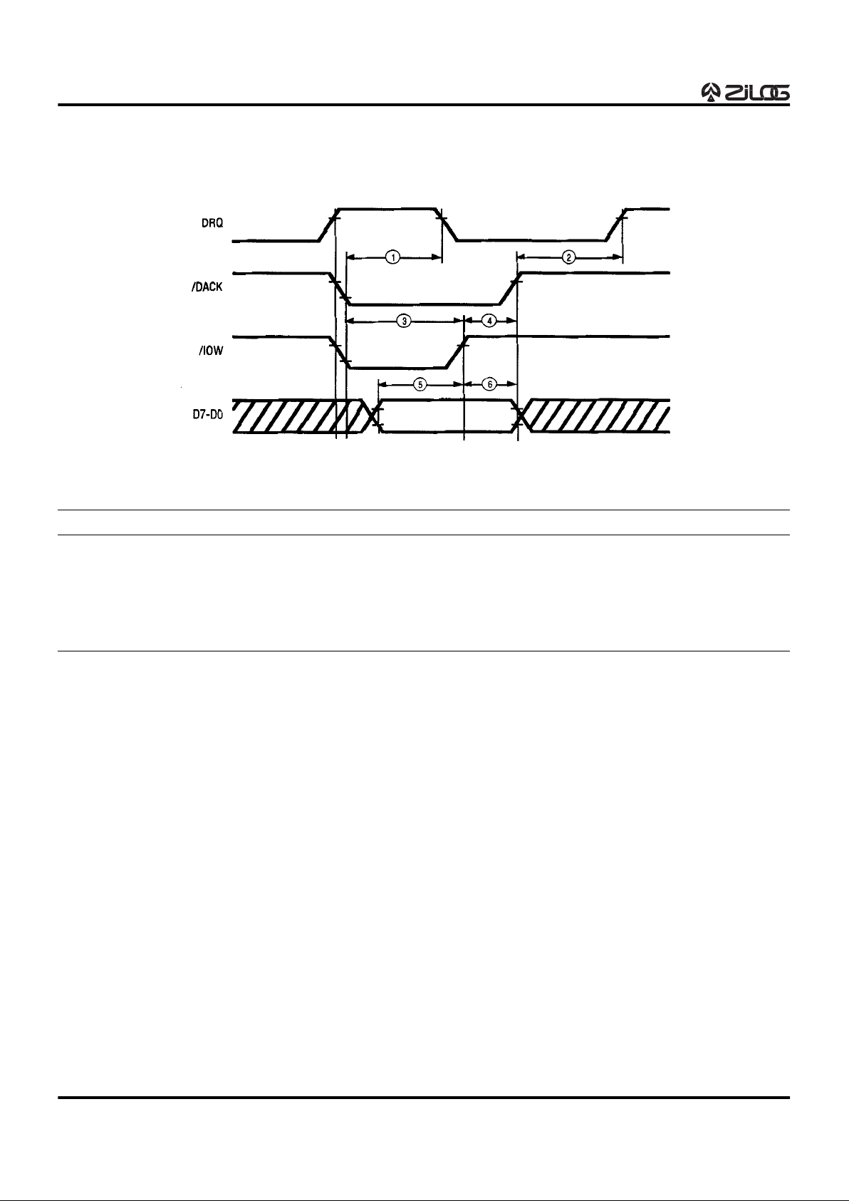
DMA Write/Playback Timing
Figure 3. DMA Write Timing Diagram
No. Description Min Max Units
1 DRQ Low from /DACK Low 130 - ns
2 /DACK High to DRQ High 30 - ns
3 Write Enable Width 100 - ns
4 /DACK Hold from End of /IOW 0 - ns
5 Data Setup to End of Write Enable 50 - ns
6 Data Hold Time from End of /IOW 40 - ns
Page 9
Z89340
Digital Wavetable Engine
DS96DSP0201
P R E L I M I N A R Y
1-9
1
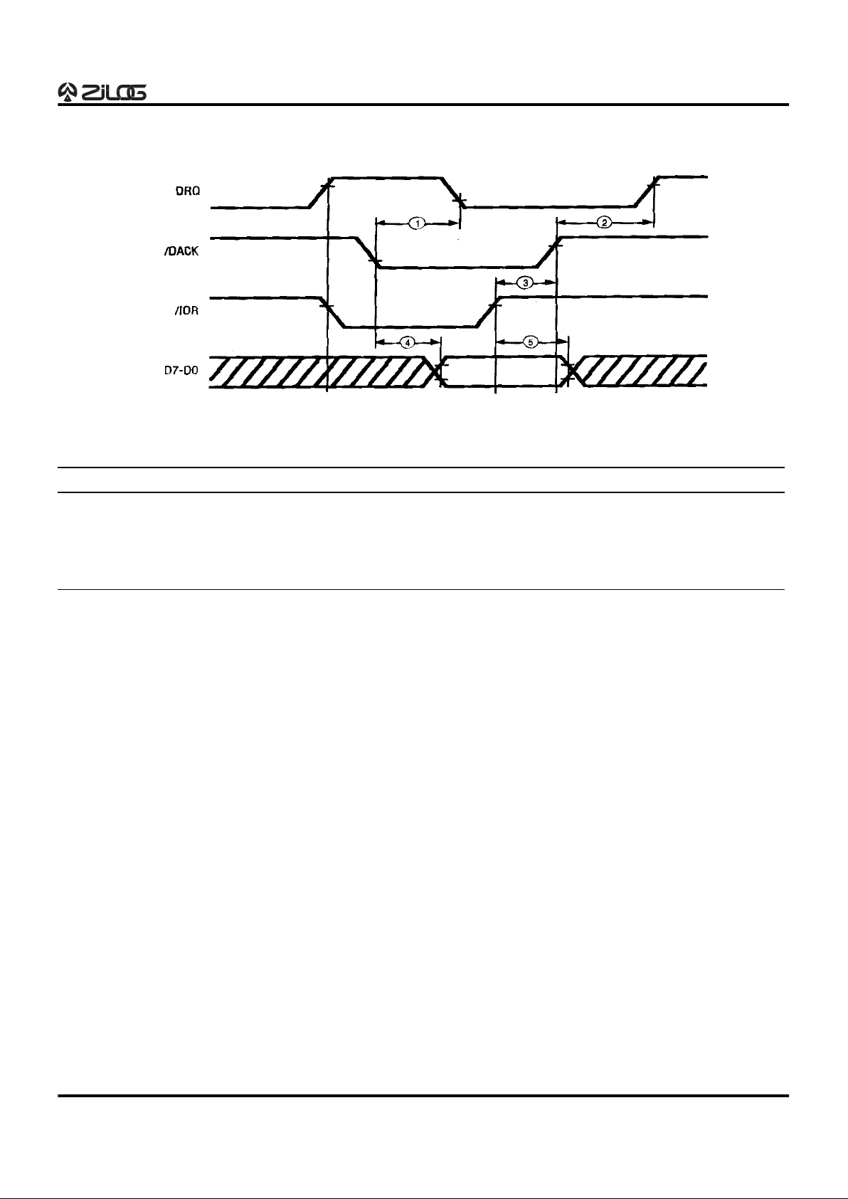
DMA Read/Record Timing Diagram
Figure 4. DMA Read Timing Diagram
No. Description Min Max Units
1 DRQ Low from /DACK Low 130 - ns
2 /DACK High to DRQ High 30 - ns
3 /DACK Hold Time from End of /IOR 0 - ns
4 Data Access Time from Read Enable 115 - ns
5 Data Hold Time from End of /IOR 20 - ns
Page 10
Z89340
Digital Wavetable Engine
1-10
P R E L I M I N A R Y
DS96DSP0201
AC CHARACTERISTICS (Continued)
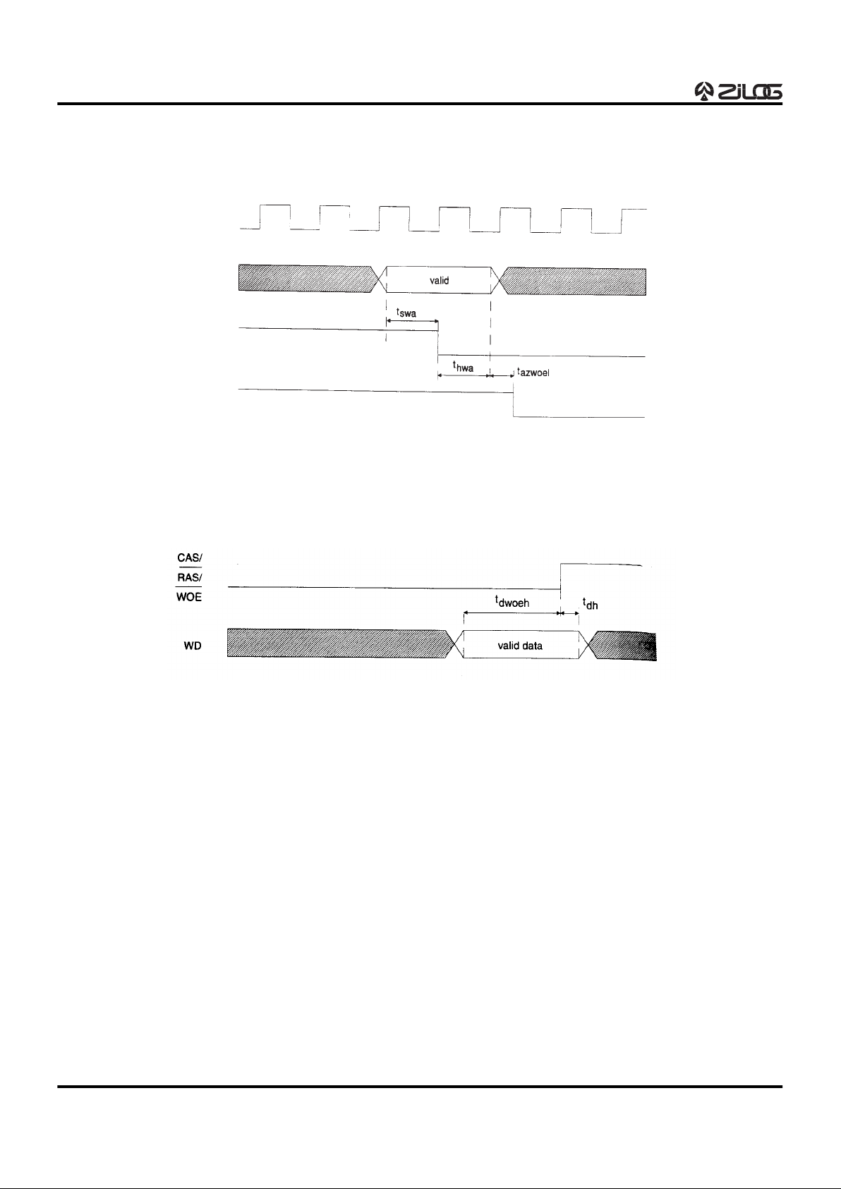
External ROM Reading Timing Diagram
Figure 5. Sample Memory Address Timing Diagram
CLK
ROMADD00–23
RAS/
CAS
WOE
(CAS Case Only)
Figure 6. Sample Memory Read Timing Diagram
Page 11
Z89340
Digital Wavetable Engine
DS96DSP0201 P R E L I M I N A R Y 1-11
1
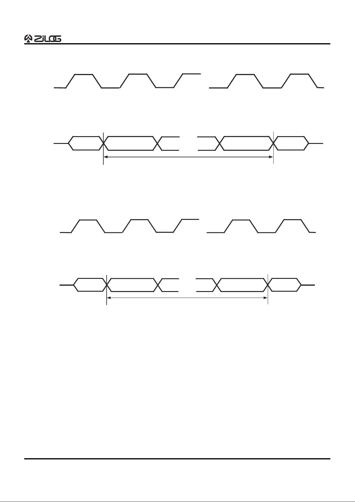
MIDI Timing Diagrams
Figure 7. MIDI Transmit Timing Diagram
MSB
MIDI_TX
SCLK
Start
Bit
Stop
Bit
LSB
. . .
. . .
8 Bits
Figure 8. MIDI Receive Timing Diagram
MSB
MIDI_RX
SCLK
Start
Bit
Stop
Bit
LSB
. . .
. . .
8 Bits
Page 12
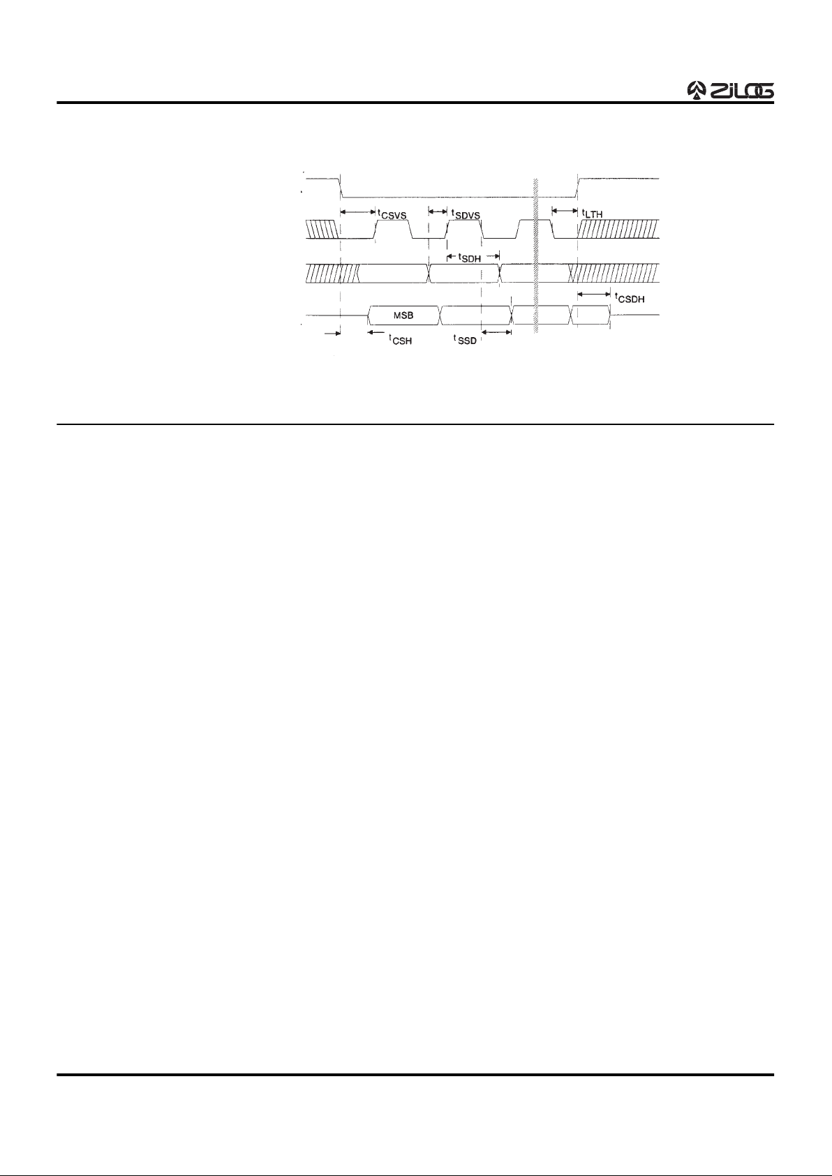
Z89340
Digital Wavetable Engine
1-12 P R E L I M I N A R Y DS96DSP0201
CODEC INTERFACE TIMING DIAGRAM
PIN FUNCTIONS
ADC_VREF_HI, ADC_VREF_LO. Analog-to-Digital Con-
verter Voltage Reference.
ADC_0–3 (I/O). Joystick button 0-3.
ADC_4–7 (Input). Game port 4-7.
AGND. Analog Ground.
AUX_CS0–3 (Ouput). Auxiliary chip-select. These pins
are used to select the CD-ROM interfaces.
AVDD. Analog Supply.
CAS (Output). Column Address Strobe Output. This mem-
ory address strobe is used in conjunction with the address
lines ROMADD01–R0MADD23.
CLKOUT (Output). Clock Output.
CODEC_SCLK (Output). Serial clock signal 0-1.
CODEC_SD_IN (Input). Serial data in 0-1.
CODEC_SD_OUT (Output). Serial data out 0-1.
CODEC_STROBE_0–3 (Output) Serial CODEC chip se-
lect strobe 0-3.
GND. Ground.
ISA_AEN (Input). ISA Bus Address Enable. This is the ad-
dress enable line and should be connected to the ISA bus
signal of the same name.
ISA_BHE (I/O). ISA Bus High Byte Enable.
ISA_DACK_01,03,05,06,07 (Input). ISA DMA Acknowl-
edge 01,03,05,06,07. These are DMA acknowledge pins
and should be connected to the appropriate ISA bus lines.
ISA_DRQ_01,03,05,06,07 (Tristate/Output). ISA DMA
Request 01,03,05,06,07. These are DMA request pins and
should be connected to the appropriate ISA bus lines.
ISA_IOCHRDY (Output). Connected to the ISA bus signal
of the same name.
ISA_IOCS16 (Tristate/Output). ISA I/0 Select 16-bit Transfer. This pin is used during 16-bit DMA transfers and
should be connected to the ISA bus signal of the same
name.
ISA_IOR (I/O). ISA I/0 Read. This is the I/0 Read. The I/0
read pulse should be connected to the ISA bus signal of
the same name.
ISA_IOW (I/O). ISA I/0 Write. This is the I/0 write pulse line
that should be connected to the ISA bus signal of the same
name.
ISA_IRQ_05,07,09,10,11 (Output). ISA Interrupt Request
05,07,09,10,11. These are Interrupt request pins and
should be connected to the appropriate ISA bus lines.
ISA_LA_17–23 (Tri-State Output). ISA Address Bus.
These lines map directly to the PC address bus; the pins
should be connected to the ISA bus address lines of the
same name.
ISA_MASTER16 (Tr-State Output). ISA Master Mode 16bit Transfer.
ISA_MEMR (I/O). ISA Memory Read.
Figure 9. CODEC Interface Timing Diagram
CODEC_STROBE_n
CODEC_SCLK_n
CODEC_SDIN_n
CODEC_SDOUT_n
Page 13

Z89340
Digital Wavetable Engine
1-13 P R E L I M I N A R Y DS96DSP0201
PIN FUNCTIONS (Continued)
ISA_MEMW (I/O). ISA Memory Write.
ISA_SA_0–4 (I/O). ISA Address Bus.
ISA_SD_08–15 (I/O). Data Bus. This data bus is used to
transfer data between PC and the Z89340. The lines map
directly to the PC data bus; the pins should be connected
to the ISA bus address lines of the same name.
MIDI_RX (Input). Receives data from MIDI interface.
MIDI_TX (Output). Sends data to MIDI interface.
MODE_S0–3 (Input). Mode Selection pins that are general
purpose input pins.
DRAM_OE (Output). External DRAM Output Enable. This
signal is an output enable strobe for external DRAM.
DRAM_WE (Output). External DRAM Write Enable. This
signal is a write enable strobe for external DRAM.
RAS (Output). Row Address Strobe Output. This memory
address strobe is used in conjunction with the address
lines ROMADD01–R0MADD23.
RESET. (Input). Device Reset.
ROMADD01–ROMADD23 (Output). Wavetable ROM Ad-
dress Bus. These lines are used to address external sample memory.
VCC. Power supply that connects to 5V ±5%.
Wave_Data_0E (Output). External Memory Output En-
able. This signal is an output enable strobe for external
sample memory.
Wave_Data_00-15 (I/O). Waveform Memory
DRAM/SRAM/ROM Data Bus. These lines are used to
pass sample data between the Z89340 and external sample memory.
Page 14

Z89340
Digital Wavetable Engine
1-14 P R E L I M I N A R Y DS96DSP0201
FUNCTIONAL DESCRIPTION
Digital Audio Input and Output
The Z89340 has eight output registers with signals that
can be sent to a DAC or CODEC. Four of these can be
used for quadraphonic output and have a panning mechanism called Polar Pan that supports motion in all four quadrants. The other four output registers are used internally as
effects channels, but can still send their serial streams to a
DAC, a second Z89340, or other digital signal processor.
The Z89340 also has eight serial input registers whose signals can be accessed and processed.
Submix Registers
The Z89340 has 16 stereo submix registers. The submix
registers are needed to chain together the various components of the reverb, chorus, echo, and flange algorithms.
When the data in a submix register is no longer needed, it
is cleared with bit 7 of the Data Source register in the parameter block of the pertinent oscillator types. The host
CPU can read and write all oscillator parameter RAM, including the submix registers.
Oscillators
The Z89340 is a special-purpose audio processor with an
instruction set designed for music synthesis. Fundamental
to the Z89340 are the 64 full-speed oscillators, the first 48
of which have a half-speed counterpart. Control of an oscillator is handled by setting the parameters in the oscillator’s 24-byte parameter block. An oscillator can be used to
generate sound, or it can be used to perform other operations-input device, tape-loop reverberator, dual tap-reader,
input mixer, and so on. Typical implementations would include an Z89340, waveform ROM and RAM, and a CPU to
control the Z89340. The CPU is normally connected via
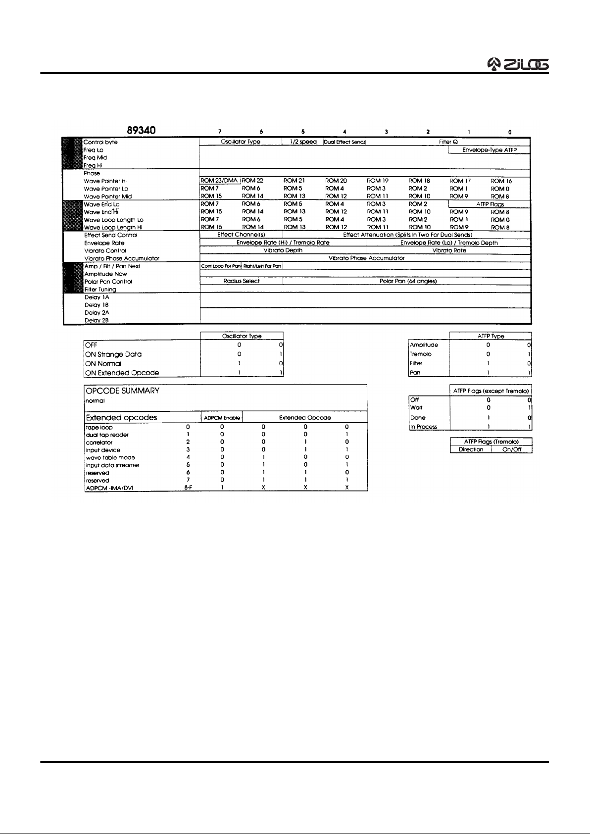
the ISA bus interface. (Refer to Figure 10 for General Purpose Oscillator Address Map.)
The following subsections briefly introduce each of the oscillator types. (A detailed description of the Oscillator Parameter Blocks for each oscillator type follows.)
Half-Speed Oscillators
Half-Speed Oscillators are best suited for playing lower
notes where the upper bandwidth is not critical, since they
operate at half the sampling rate.
Oscillators 0 through 47 (0x2f) can each be split into two
oscillators operating at half the clock rate. This yields 112
oscillators total (2 . 48 + 16). Oscillators 48 through 63
(0x30 through 0x3f) can only operate at the full clock rate
since the parameter RAM that would be needed for their
half-speed counterparts is unavailable
They can also be used for higher notes with simple waveforms that have few significant upper harmonics. For ex-
ample, at a sampling rate of 48 kHz, the Half-Speed Oscillators will have a sampling rate of 24 kHz, so the maximum
frequency that can be produced by these oscillators without aliasing is under 12 kHz. This bandwidth is adequate
for many sounds, but not suitable for high strings, cymbals,
or other crisp or bright sounds. An empirical listening test
will help determine if a Half-Speed Oscillator can be used
for a particular situation. The obvious advantage to using
Half-Speed Oscillators wherever possible is that more
notes can be played at the same time.
Sample Loop Oscillators/Wavetable Mode
Oscillators
For music synthesis, the Z89340 Sample Loop and Wavetable Mode Oscillators are the main workhorses. They are
interpolating wavetable look-up oscillators and perform the
tasks of fetching two adjacent samples from waveform
memory. They interpolate between them based on the current phase angle (frequency and time), filtering, scaling,
and routing the resulting signal to multiple effects sends
and output channels. These oscillators can use 8- or 16-bit
linear PCM samples. The ADPCM oscillators described
later are similar in function and use ADPCM (IMA and DVI
4- or 8-bit samples).
Sample Loop Oscillators
Sampling
One of the more popular methods of re-creating or re-synthesizing the sound of a traditional acoustic musical instrument is through a process referred to as sampling or PCM
(pulse-code modulation) synthesis. A sample, in the strictest sense, is a value taken at a specified point in time that
represents the instantaneous amplitude of the subject
waveform. A digital recording consists of a sequence of
amplitude values sampled at evenly spaced intervals of
time. The term “sample” sometimes refers to the sequence
of samples found in a digital recording. (This usage is especially popular throughout the music industry.) This digital recording is much like the recording that would be captured with a tape recorder, except that it can be stored in
digital memory, and as such, can be randomly accessed.
Looping
To reduce the length of the recording to make it fit in a limited memory space, the most common form of processing
used with sampling is looping. The process of looping can
be briefly described as follows: The synthesizer plays the
original recording of a note up to a designated time point,
whereupon it plays a short sequence of samples that describe one or more periods of the temporally varying waveform-the “loop.” The loop is then repeated until the note
stops. A decaying amplitude envelope is often imposed
upon the loop so that the sound will decay naturally. The
Sample Loop Oscillator is designed to facilitate looping algorithms with single or multiple loops.
Page 15

Z89340
Digital Wavetable Engine
DS96DSP0201 P R E L I M I N A R Y 1-15
1
Wavetable Synthesis
Another method of synthesizing sound is sometimes
called wavetable synthesis. The Wavetable Mode Oscillator has some wavetable-synthesis extensions that set it
apart from the Sample Loop Oscillator. With wavetable
synthesis, one or more complete periods of a waveform
are recorded and stored in a wavetable. The wavetable is
then played at the desired frequency. This is similar to the
loop described earlier except that the wavetable is often
not a recording, but a single period of a sound created
through additive synthesis. The Z89340 can move to other
wavetables or stay on the same wavetable during the life
of a note.
To play a note or sample sequence from waveform ROM,
you would set the following: desired frequency, wave begin and end addresses, wave loop length, the initial amplitude envelope begin and end values, envelope rate, Amplitude/Tremolo/Filter/Pan (ATFP) envelope type to
amplitude, output channel(s), effects send(s), pan location, and filter tuning values. All of these settings can be
changed during the life a note as desired. All oscillators are
completely independent of each other, even for features
such as vibrato rate and filter cutoff points.
The Z89340 assumes that the amplitude envelope will occur in multiple segments-attack segment, several initial decay segments, possibly a sustained segment, and several
final decay segments. On-chip support is given for one envelope segment at a time. An interrupt is generated when
the segment end is reached, at which time the host CPU
will set up the next amplitude segment, supplying a new
amplitude end value and envelope rate (the slope that defines how long it will take to reach the end amplitude). It is
not critical that the interrupt be serviced immediately; a delay of 10–20 milliseconds (ms) normally is not noticed; the
amplitude merely remains stationary until the new segment is initiated. The Z89340 has amplitude steps well below the threshold of perceptibility, so there is no zipper
noise. If there is a sustained segment (one where the amplitude does not change), the Envelope-type ATFP controls can be used to define the envelope rate parameter as
tremolo rate; tremolo depth can then be set. If tremolo is
not needed, the ATFP envelope system can also be used
for variable pan or swept filter. (Refer to the Oscillator Parameter Block section for a detailed description of each
control bit.)
Vibrato is independent of the ATFP system. There are 16
settings of vibrato rate ranging from 0.1–10 Hz, and 16 different settings of vibrato depth ranging from plus or minus
a few cents to two semitones.
Note: A semitone is equivalent to 21/12 frequency
multiples; a cent is equivalent to 21/1200 frequency
multiples.
The vibrato value, which is derived from a sinewave indexed by the vibrato phase accumulator, is added to or
subtracted from the frequency. The initial vibrato phase
can be set by writing a value to the 8-bit vibrato phase accumulator-value of 64 is π/2 radians, which would start the
vibrato at maximum positive swing.
Each oscillator has its own second-order (two-pole, twozero) digital filter. At the initialization of an oscillator, the
two delays should be given values of 0 unless a click is desired. The filter Q (in the Control Byte) and the filter tuning
value are used together to set the desired characteristics
of the filter. Low-pass filters with varying amounts of Q are
available. A few useful high-pass and band-pass filter settings are also provided. The ATFP envelope system can
be used to create a variable or swept low-pass filter. (Refer
to the tables in the Oscillator Parameter Block section for
details.)
The Polar Pan Control provides selection of output channels and pan between or among up to four output channels. When four channel quadraphonic output is selected,
the spatial location is specified with a modified polar coordinate-a value of 16 is π/2 radians. The radius select is a
two-bit number with 2 at the edge of the circle and 0 near
the center of the circle. A radius of 3 is reserved for stereo
panning when only two output channels are needed. (Other items such as effects channels and submix channels
are covered in sections that follow.) All parameters in the
Oscillator Parameter Block can be modified by the CPU
during the life of a note.
Page 16
Z89340
Digital Wavetable Engine
1-16 P R E L I M I N A R Y DS96DSP0201
FUNCTIONAL DESCRIPTION (Continued)
Figure 10. General-Purpose Oscillator Address Map
Page 17
Z89340
Digital Wavetable Engine
DS96DSP0201 P R E L I M I N A R Y 1-17
1
ADPCM Oscillator
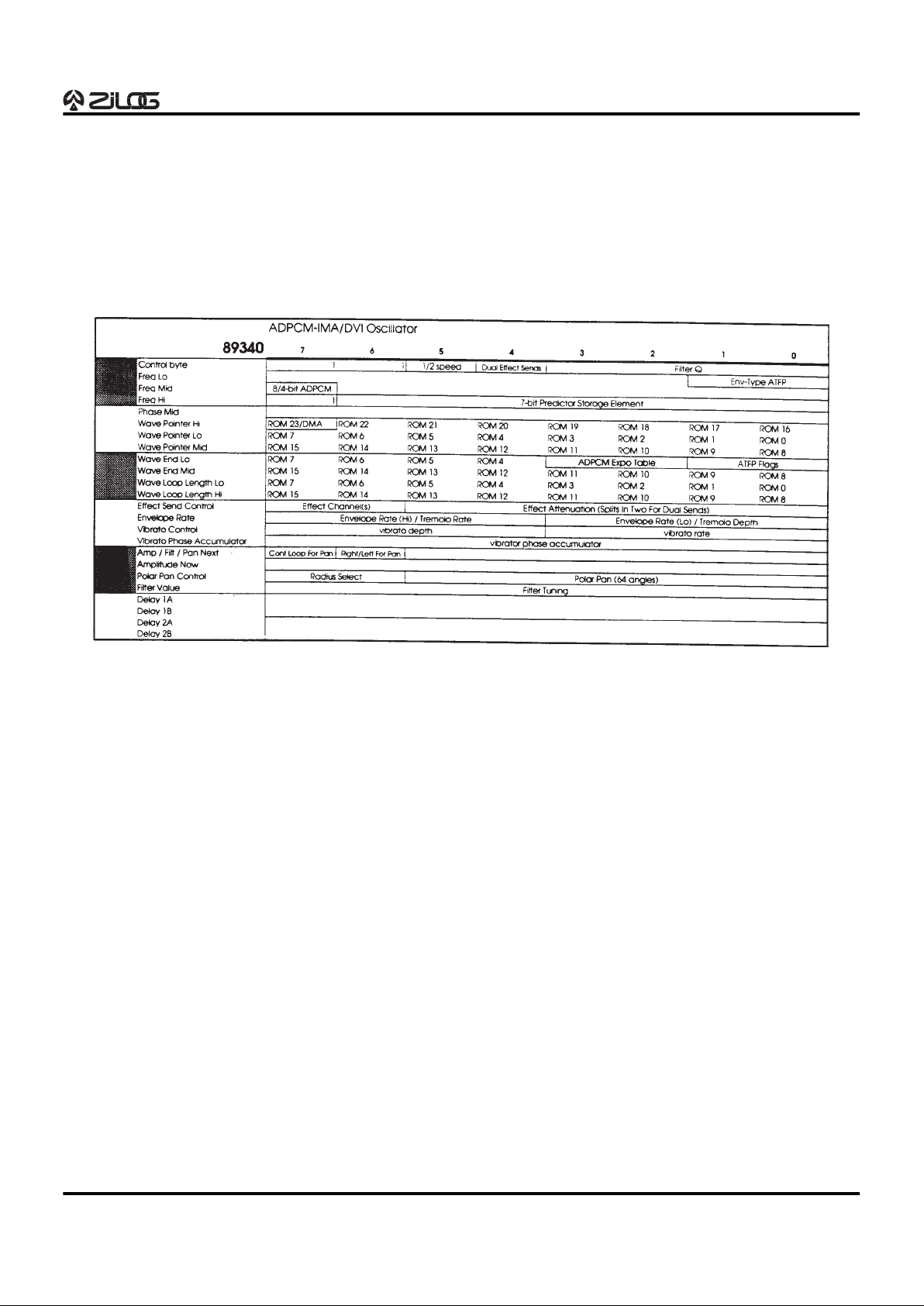
The ADPCM Oscillator works in much the same way as the
Sample Loop and Wavetable Oscillators. The main differences are that, due to the nature of ADPCM, the frequency
cannot be negative (you cannot with the Sample Loop Oscillator you can play a sound backwards, with Wavetable
Mode and ADPCM), and ADPCM will not allow playing a
sound faster than the sampling rate at which it is stored in
ROM. Also, the wavetable synthesis extensions of the
Wavetable Mode Oscillator are not available. The Z89340
handles IMA/DVI format ADPCM in 4- and 8-bit modes.
The ADPCM Oscillator provides a way to compact the data, but with some degree of sound degradation. However,
in many applications the trade-off may be worthwhile. (Refer to Figure 11 for ADPCM-IMA/DVI Oscillator Address
Map).
Figure 11. The ADPCM-IMA/DVI Oscillator Address Map
Page 18
Z89340
Digital Wavetable Engine
1-18 P R E L I M I N A R Y DS96DSP0201
FUNCTIONAL DESCRIPTION (Continued)
Tape Loop Oscillator
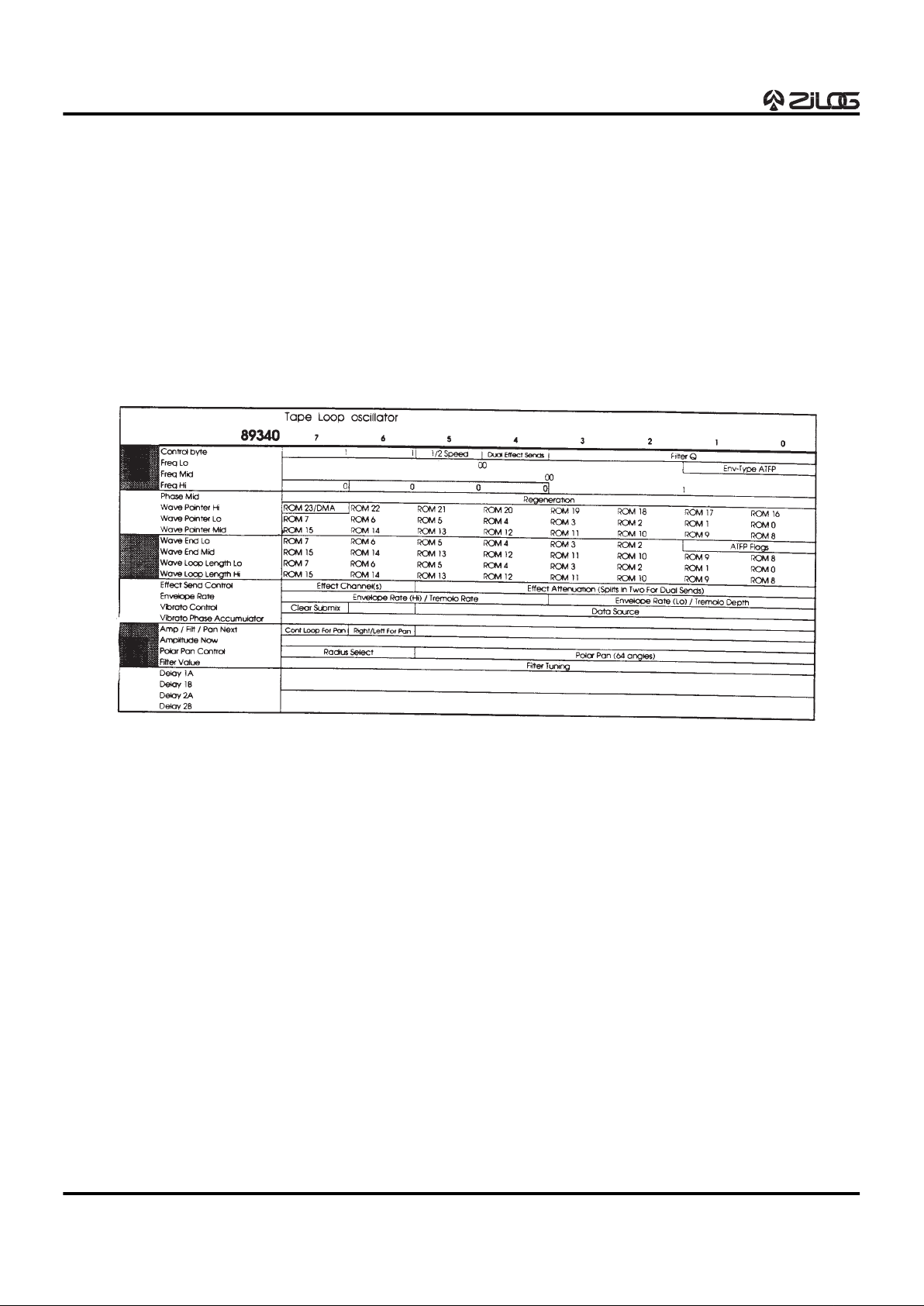
The Tape Loop Oscillator takes its input from an input register, an effects channel, or a submix register. It then reads
a sample from wave RAM, and writes the scaled input value plus the scaled and filtered sample from wave RAM
back to the same location in wave RAM. It behaves very
much like a tape recorder with a loop of tape, hence the
name “Tape Loop.” Echo and single-delay reverberation
can be accomplished with the Tape Loop Oscillator. The
amount of delay is set with the Wave Loop Length registers, and can be more than a second if you are willing to
dedicate the necessary RAM. This oscillator can also be
used to transfer input from a ADC that is connected to one
of the input registers. In this way the input can be buffered
in RAM for later use by the CPU host, or processing can
be done by the Z89340 before sending the signal to a stereo submix register pair or one or more output channels.
The Tape Loop Oscillator can also perform the function of
the comb filter component of reverb algorithms (Figure
12).
Figure 12. The Tape Loop Oscillator Address Map
Page 19
Z89340
Digital Wavetable Engine
DS96DSP0201 P R E L I M I N A R Y 1-19
1
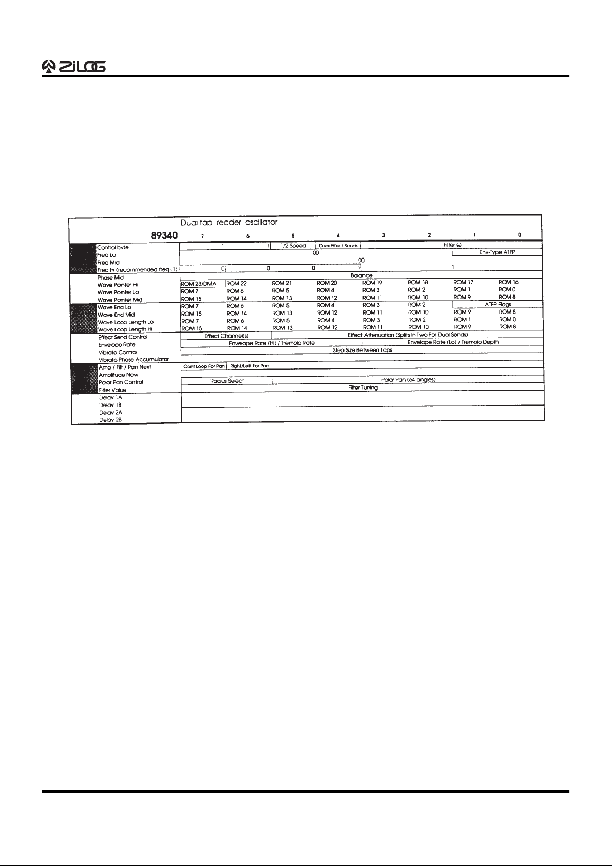
Dual Tap-Reader
As part of the reverb algorithm, the Dual Tap-Reader Oscillator can pick additional taps in the Tape Loop delay line.
The samples gathered are then scaled, summed, filtered,
and sent to a submix register or one or more output channels. Note that the filtering takes place after scaling and
summing since there is only one filter in the Dual TapReader. The taps supplied by the Dual Tap-Reader can be
used to simulate early reflections. The two taps can be up
to 4096 samples apart, which is about 80 ms at a 50 kHz
sampling rate. However, the reverb system is typically run
with Half-Speed Oscillators, making possible 160 ms or
more between taps. As many Dual Tap-Readers as desired can be used with a single Tape Loop Oscillator providing the input (Figure 13).
Figure 13. The Dual Tap-Reader Oscillator Address Map
Page 20
Z89340
Digital Wavetable Engine
1-20 P R E L I M I N A R Y DS96DSP0201
FUNCTIONAL DESCRIPTION (Continued)
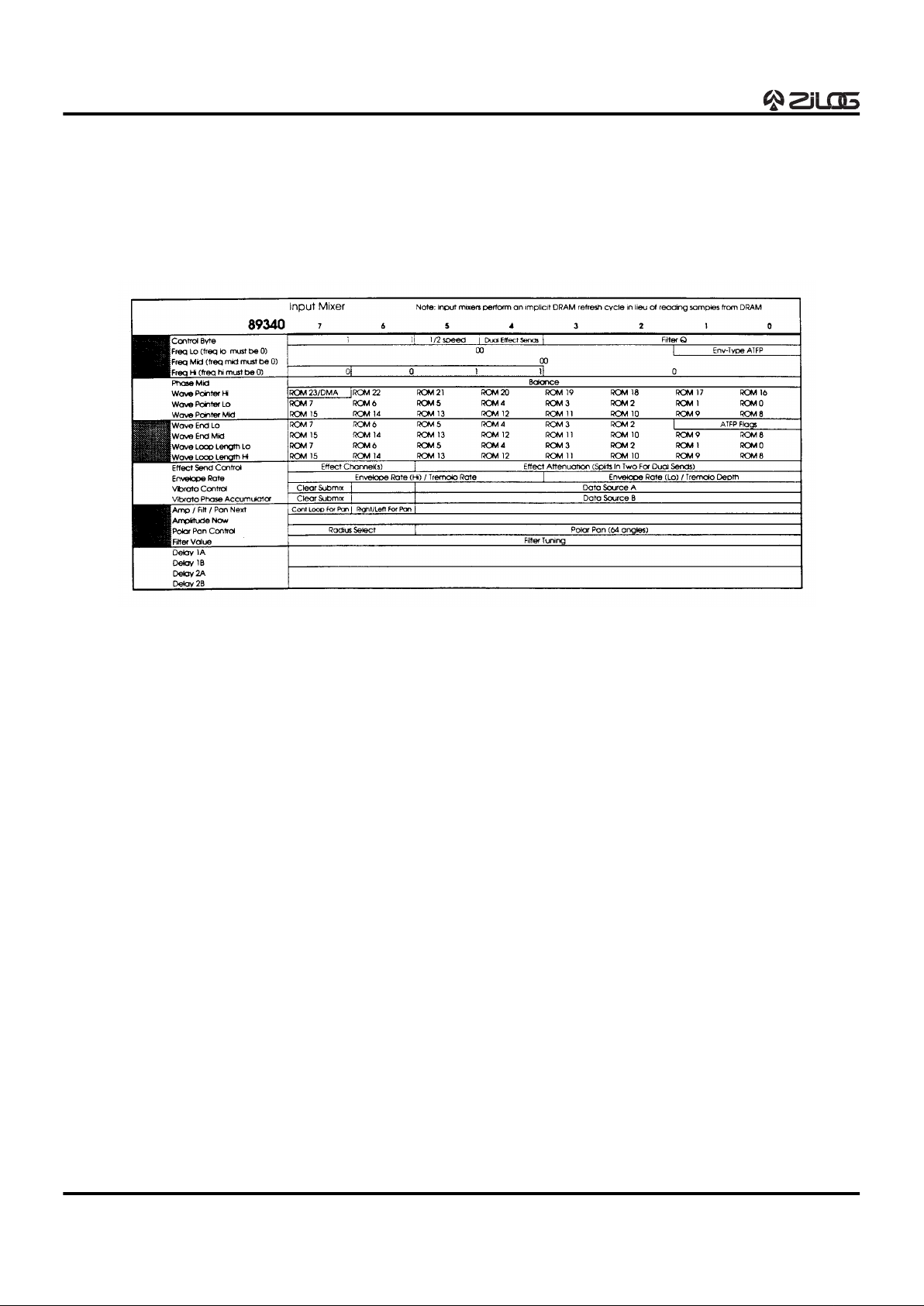
Input Mixer
The Input Mixer reads input from two sources (input registers, submix registers or effects channels), scales the two
samples, sums, filters, and sends the output to the desired
channel(s). The Input Mixer also performs the DRAM refresh task (Figure 14).
Figure 14. The Input Mixer Address Map
Page 21
Z89340
Digital Wavetable Engine
DS96DSP0201 P R E L I M I N A R Y 1-21
1
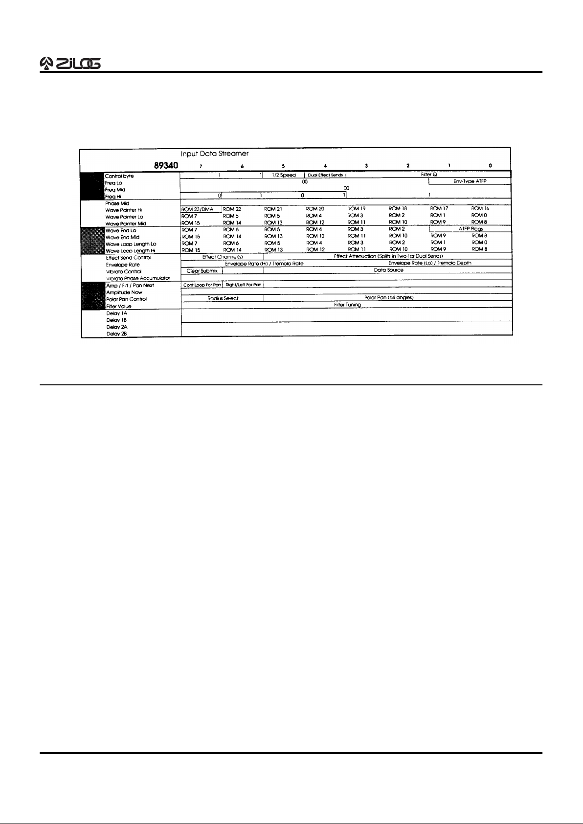
Input Data Streamer
Samples can be moved via DMA from the CPU host RAM
to the Z89340 wavetable RAM space. Up to 48 channels
of bus-mastered DMA are available (Figure 15).
OSCILLATOR PARAMETER BLOCKS
An oscillator is controlled by the host CPU by writing commands in the on-chip RAM that is associated with the oscillator. This RAM is called the Oscillator Parameter Block.
The following pages present, for each of the oscillator
types, a description of the bit fields in the 24 bytes of the
Oscillator Parameter Block. Address 0 in the block is the
Control Byte.
The two bits of Oscillator Type deserve special mention.
Extended Opcodes are enabled when both of these bits
are set, and the high four bits of Frequency Hi specify
which extended opcode to use. Because the Sample Loop
and Wavetable Mode oscillators are so similar, they are
presented together. The Wavetable Mode oscillator, however, is an extended opcode.
Sample Loop/Wavetable Mode Oscillators
Control Byte address 0
Filter Q bits 0-3
Each oscillator has a variable filter. These bits allow adjustment of the filter Q. (Refer to Filter Tuning Value for
more information.)
Dual Effect Sends bit 4
When this bit is set, the oscillator talks to two effect channels-the effect channel chosen with Effect Channel in the
Effect Send Control Byte, and the subsequent channel
(wraps to effects channel 0 if the last channel is chosen).
This system allows choosing two of the four effects channels at a time in all but two of the possible combinations.
Half-Speed bit 5
Half-speed: Oscillators 0 through 47 (0x2f) can each be
split into two oscillators operating at half the clock rate.
This yields 112 oscillators total (2
.
48 + 16).
Oscillators 48 through 63 (0x30 through 0x3f) can only operate at the full clock rate since the parameter RAM is unavailable that would be used as their half-speed counterparts.
Oscillator-type bits 6-7
These bits define the operating mode of the oscillator:
00-If all 8 bits of the Control Byte are 0, the oscillator shuts
off completely regardless of the settings of the other parameters. To prevent an oscillator from sending output to
any channel without shutting it down, use the special silence command in the Polar Pan control.
01-8-bit linear PCM wavetable data.
10-16-bit linear PCM wavetable data.
11-extended opcode. For Wavetable Mode, set the upper
four bits of Frequency Hi to 0100.
Figure 15. The Input Data Streamer Address Map
Page 22

Z89340
Digital Wavetable Engine
1-22 P R E L I M I N A R Y DS96DSP0201
OSCILLATOR PARAMETER BLOCKS (Continued)
Frequency Low address 1
Envelope-type ATFP bits 0 and 1
Four types of envelope segments are supported, but only
one at a time. Amplitude/Tremolo/Filter/Pan Envelopetype control bits.
00-Amplitude
01-Tremolo
10-Filter
11-Pan.
Frequency Low bits 2-7
These are the lowest six bits of the 22-bit linear frequency
Frequency Mid address 2
bits 0-7
These are the middle eight bits of the 22-bit linear frequency.
Frequency Hi address 3
Frequency Hi bits 0-7
(Sample Loop Oscillator only)
These are the highest eight bits of the 22-bit linear frequency. Frequency is represented as a linear two's-complement value. A negative frequency plays the sound
backwards.
Frequency Hi bits 0-3
(Wavetable Mode Oscillator only)
These are the highest four bits of the 18-bit linear frequency. Frequency is represented as an unsigned linear value.
With the Wavetable Mode Oscillator, the upper four bits
are an extended opcode and must be 0100; negative frequencies are not possible with the remaining 18 bits of linear frequency.
Extended Opcode bits 4-7
(Wavetable Mode Oscillator only)
With the Wavetable Mode Oscillator, the upper four bits of
Frequency Hi are one of the extended opcodes and must
be 0100.
Phase address 4
Phase bits 0-7
The eight bits of Phase, along with the 16 bits of Wave
Pointer Mid and Lo, are that part of the wave address that
is modified by the oscillator through the life of the note as
it steps from sample to sample based on frequency. The
upper bits of the wave ROM address are set at initialization
and remain fixed (Wave Pointer Hi). Wave Pointer Lo
points to a sample in ROM or RAM. Phase gives the distance between the sample and the subsequent sample.
The oscillator does a piecewise linear interpolation between the two samples. To further reduce conversion error, eight bits of smoothing are added below Phase in the
internal processing. Phase is generally given a value of 0
at the start of a note.
Wave Pointer Hi address 5
ROM16-ROM23 bits 0-7
The eight bits of Wave Pointer Hi control wave ROM or
RAM address lines 16-23, which are the highest address
bits. This value remains fixed throughout the life of a note.
The lower bits of Wave Pointer are changed by the Z89340
during the life of a sound until they equal Wave Endpoint.
ROM23/DMA bit 7
If DMA bus-mastering mode is enabled, this bit enables
DMA for the oscillator. The address then becomes an ISA
Bus host CPU RAM address. DMA has system consequences and should be used with caution. In particular,
fewer oscillators can be active at the same time. Tape
Loops should not be used because of limitations of data
transmission across the ISA bus.
Wave Pointer Lo address 6
ROM0-ROM7 bits 0-7
The eight bits of Wave Pointer Lo are part of the wave address that is modified by the oscillator through the life of
the note as it steps from sample to sample based on frequency corresponding to ROM or RAM address bits 0-7.
The upper bits of the wave ROM address are set at initialization and remain fixed (Wave Pointer Hi). Wave Pointer
Lo points to a sample in ROM or RAM. (Refer to Phase
and Wave Pointer Mid.) Wave Pointer Lo contains the lowest bits of the start address when a note is begun.
Wave Pointer Lo and Wave Pointer Mid are changed by
the Z89340 during the life of a sound until they are equal
Wave Endpoint.
Wave Pointer Mid address 7
ROM8-ROM15 bits 0-7
The eight bits of Wave Pointer Mid point to a block of 256
samples. This 256 sample block can be considered a
wavetable for use in wavetable synthesis. For sample-sequence playback, Wave Pointer Mid forms the upper eight
bits of the 16-bit sample pointer; Wave Pointer Lo holds
the lower eight bits. This allows sample sequences of up
to 64K samples. Wave Pointer Mid contains eight bits of
the start address when a note is begun. Wave Pointer Lo
and Wave Pointer Mid are changed by the Z89340 during
the life of a sound until they equal Wave Endpoint.
Page 23

Z89340
Digital Wavetable Engine
DS96DSP0201 P R E L I M I N A R Y 1-23
1
Wave Endpoint Lo/
AWS/Interleave Size address 8
ATFP Flags bits 0 and 1
These bits are active for the selected envelope types in
Frequency Lo. The bits have a separate meaning for
Tremolo from the other types.
Amplitude/Filter/Pan envelope flag bits:
00-Off
01-Wait
10-In process
11-Done
Tremolo envelope flag bits:
bit 0-Enable
bit 1-Polarity
Interleave Size bits 2-3
(Wavetable Mode Oscillator only)
With wavetable synthesis, one or more complete periods
of a waveform are stored in a wavetable. Interleave is the
distance between wavetables. Normally Interleave Size
will equal Table Size so that the wavetable will be contiguous. For compatibility with existing sound libraries, other
interleaves are available.
00-64 Samples
01-128 Samples
10-256 Samples
11-512 Samples
AWS bit 4
(Wavetable Mode Oscillator only)
With wavetable synthesis, one or more complete periods
of a waveform are stored in a wavetable. We Change the
Wave Endpoint when we want to move to the next wavetable. How the sound moves from the current wavetable to
the next is controlled by AWS (Automatic Wave Select).
When AWS is 0, the sound loops on the current wavetable
as long as Wave Endpoint equals Wave Pointer. When
Wave Endpoint is changed, the Z89340 jumps to the
wavetable pointed to by Wave Endpoint as soon as it plays
the last sample of the current wavetable pointed to by
Wave Pointer. Wave Pointer is then set equal to Wave
Endpoint. When AWS is 1, all samples in the wavetables
between Wave Pointer and Wave Endpoint are also
played. The Z89340 the loops on the wavetable pointed to
by Wave Endpoint.
ROM5-ROM7 bits 5-7
(Wavetable Mode Oscillator only)
With wavetable synthesis, one or more complete periods
of a waveform are stored in a wavetable. The wavetable
can be played at any desired frequency.
ROM2-ROM7 bits 2-7
(Sample Loop Oscillator only)
For sample loop systems, Wave Endpoint is the last sample in the sample sequence. When this last sample is
played, the Z89340 subtracts Wave Loop Length from the
Wave Pointer. Note that since only six bits are available for
Wave Endpoint Lo, the sample sequence can only end on
every fourth address. Wave Loop Length does not have
this restriction.
Wave Endpoint Hi address 9
ROM8-ROM15 bits 0-7
(Refer to Wave Endpoint Lo.)
Wave Loop Length Lo address A
Table Size bits 0 and 1
(Wavetable Mode Oscillator only)
With wavetable synthesis, one or more complete periods
of a waveform are stored in a wavetable. Table Size is the
size of the wavetable. Interleave is the distance between
wavetables. Normally Interleave Size will equal Table Size
so that the wavetable will be contiguous. For compatibility
with existing sound libraries, other interleaves are available.
00-64 Samples
01-128 Samples
10-256 Samples
11-512 Samples
ROM2-ROM7 bits 2-7
(Wavetable Mode Oscillator only)
For Wavetable Mode Oscillators, this should be 0.
ROM0-ROM7 bits 0-7
(Sample Loop Oscillator only)
A sample sequence is played by setting Wave Pointer to
the first sample in the sequence and Wave Endpoint to the
last sample in the sequence. For many sounds, we then
repeat or loop the last portion of the sequence. Wave Loop
Length is the length of the loop.
Wave Loop Length Hi address B
ROM8-ROM15 bits 0-7
(Refer to Wave Loop Length Lo.)
For Wavetable Mode Oscillators, this should be 0.
Page 24

Z89340
Digital Wavetable Engine
1-24 P R E L I M I N A R Y DS96DSP0201
OSCILLATOR PARAMETER BLOCKS (Continued)
Effects Send Control address C
Effects Attenuation(s) bits 0-5
These six bits control the amount of signal that will be sent
to the selected Effects Channel (bits 6-7). Since the signal
will be sent to two effects output channels if the Dual Effect
Sends bit in the Control Byte is set, the Effects attenuation
splits into two 3-bit attenuation values, with bits 0-2 as the
attenuation for the channel selected by the Effects Channel, and bits 3-5 as the attenuation for the subsequent
channel.
Effects Channel bits 6-7
These two bits are used to select one of four effects output
channels. These output channels can be used internally by
the Z89340, and they can also be sent to a DAC or CODEC. If the Dual Effect Sends bit in the Control Byte is set,
the signal will be sent to two effects channels, the one selected here and the subsequent channel.
Envelope rate address D
When ATFP selects Amplitude, Filter, or Pan:
Envelope Rate bits 0-7
With Amplitude, the eight bits of Envelope Rate are an unsigned exponential representation of the slope between
the amplitudes at the two envelope segment ends. This is
the rate that defines how long it will take to reach the end
amplitude, Amplitude Next. An interrupt is generated when
the segment end is reached, at which time the host CPU
will set up the next amplitude segment, supplying a new
Amplitude Next value and Envelope rate. A similar procedure is followed when ATFP selects Filter or Pan.
When ATFP selects Tremolo:
Tremolo Rate bits 0-3
The four bits of Rate are an unsigned exponential number
that give rates ranging from 0.1 to 10 Hz.
Tremolo Depth bits 4-7
These four bits specify depths of 1.5 to 24 decibels.
Amp/Filt/Pan Next address E
When ATFP selects Amplitude:
Amplitude Next bits 0-7
Amplitude is expressed in an unsigned logarithmic unit
called a hexadecibel or “hexabel” for short. The upper four
bits of the hexabel are a base-two exponent and the lower
four bits form the mantissa. There are 256 hexabel steps
in 96 decibels, so 2.667 hexabels = 1 decibel. At the initialization of a note, set Amplitude Now and Amplitude Next
with the endpoints of an amplitude envelope segment.
Also set the Envelope Rate. For subsequent amplitude en-
velope segments, only set Amplitude Next and Envelope
Rate, because Amplitude Now always equals Amplitude
Next at the end of an envelope segment.
When ATFP selects Filter:
Filter Tuning Next bits 0-7
Filter Tuning Next works in a way similar to Amplitude
Next.At the initialization of a filter envelop segment, set Filter Tuning value and Filter Tuning Next with the endpoints
of the filter envelope segment. Also set the Envelope Rate.
When ATFP selects Pan:
Pan Angle Next bits 0-5
Pan Next works in a way similar to Amplitude Next or Filter
Tuning Next, except that there are only six bits of pan position. At the initialization of a pan segment, set Polar Pan
Angle and Pan Angle Next with the endpoints of the pan
envelope segment. Also set the Envelope Rate.
Pan Direction bit 6
A 1 indicates counterclockwise rotation, and a 0 indicates
clockwise rotation.
Pan Continuous Loop bit 7
If this bit is a 0, an interrupt is generated to let the host CPU
know that the panning has completed. If this bit is set, pan
continues around this circle indefinitely. No interrupt is
generated when Pan Angle Next is reached.
Amplitude Now address F bits 0-7
(Refer to the previous discussion on Amplitude Next.) If
ATFP amplitude envelopes are not being used, this will be
the amplitude of the oscillator—a steady or sustained amplitude segment. Amplitude Now can be changed whenever desired; however, changing Amplitude Now more than
1 hexabel will usually cause a noticeable click. Even a 1
hexabel change will sometimes cause a click. To eliminate
clicks or zipper noise, use the amplitude envelope system.
Polar Pan Control address 10
Polar Pan Angle bits 0-5
There are four main output channels. The spatial location
among them is specified with a modified polar coordinate—a value of 16 is π/2 radians, 32 is π radians, 48 is
3π/2 radians, and so on.
Polar Pan Radius bits 6-7
The radius select is a two-bit number with 2 at the edge of
the circle and 0 near the center of the circle. A radius of 3
is reserved for stereo panning when only two output channels are needed. When the radius is 3, the following special values of Pan Polar Angle are defined:
Page 25

Z89340
Digital Wavetable Engine
DS96DSP0201 P R E L I M I N A R Y 1-25
1
Filter Tuning Value address 11
bits 0-7
This byte specifies what the coefficients of the second-order (two-pole, two-zero) digital filter should be in order to
characterize the response. The filter Q can also be adjusted.
Vibrato Control address 12
Vibrato Rate bits 0-3
The four bits of Rate are an unsigned exponential number
that give rates ranging from 0.1 to 10 Hz.
Vibrato Depth bits 4-7
These four bits specify depths ranging from plus and minus a few cents to about two semitones.
Vibrato Phase
Accumulator address 13
The vibrato value is derived from a sinewave represented
by the 8-bit vibrato phase accumulator and is added to or
subtracted from the frequency. The initial vibrato phase
can be set by writing a value to the 8-bit vibrato phase accumulator—a value of 64 is π/2 radians, which would start
the vibrato at maximum positive swing. If you want the vibrato to swing flat first, initialize the Vibrato Phase Accumulator to 128, corresponding to π radians, a zero crossing
in the sinewave just before it swings negative.
Delay 1A address 14
Delay 1B address 15
Delay 2A address 16
Delay 2B address 17
Each oscillator has its own second-order (two-pole, twozero) digital filter. At the initialization of an oscillator, these
two delays should be given values of 0 unless a click is
wanted. If desired, the oscillator audio stream can be examined or modified by accessing the delay registers.
Oscillator Parameter Block for the Tape Loop
Oscillator
Control Byte address 0
Filter Q bits 0-3
Each oscillator has a variable filter. These bits allow adjustment of the filter Q. (Refer to Filter Tuning value for
more information.)
Dual Effect Sends bit 4
When this bit is set, the oscillator talks to two effect channel, so the effect channel chosen with Effect Channel in
the Effect Send Control Byte, and the subsequent channel
(wraps to effects channel 0 if the last channel is chosen).
This system allows choosing two of the four effects channels at a time in all but two of the possible combinations.
Half-Speed bit 5
Half-Speed: Oscillators 0 through 47 (0x2f) can each be
split into two oscillators operating at half the clock rate.
This yields 112 oscillators total (2
.
48 + 16).
Oscillators 48 through 63 (0x30 through 0x3f) can only operate at the full clock rate since the parameter RAM that
would be used as their half-speed counterparts is unavailable.
Oscillator-type bits 6-7 11-extended
opcode
These bits define the operating mode of the oscillator.
Since Tape Loop is an extended opcode, both bits will be
set to 1. For Tape Loop, set the upper four bits of Frequency Hi to 0000.
Frequency Low address 1
Envelope-type ATFP bits 0 and 1
Four types of envelope segments are supported, but only
one at a time. Amplitude/Tremolo/Filter/Pan Envelopetype control bits.
00-Amplitude
01-Tremolo
10-Filter
11-Pan
Frequency Low bits 2-7
Always 0 for Tape Loop.
Frequency Mid address 2
bits 0-7
Always 0 for Tape Loop.
0-f stereo pan FRONT channels left to right.
20-2f stereo pan REAR channels left to right.
3d sent to one of 32 submix registers. The submix
register is chosen with low five bits of the Effects
Send Control. Submix registers can be selected
as inputs by Tape Loop oscillators (an extended
opcode).
3e mute the oscillator. The oscillator continues to do
everything else except connect to an output
channel.
3f sends output to all four output channels equally,
effectively at the center of the circle.
Page 26

Z89340
Digital Wavetable Engine
1-26 P R E L I M I N A R Y DS96DSP0201
OSCILLATOR PARAMETER BLOCKS (Continued)
Frequency Hi address 3
Frequency Hi bits 0-3
These are:
Extended Opcode bits 4-7
With the Tape Loop Oscillator, the upper four bits of Frequency Hi are one of the extended opcodes and must be
0000.
Phase address 4
Regeneration bits 0-7
This value controls the amount of delayed signal that gets
mixed back into the input of the delay line.
Wave Pointer Hi address 5
ROM16-ROM23 bits 0-7
The eight bits of Wave Pointer Hi control wave ROM or
RAM address lines 16-23, which are the highest address
bits. This value remains fixed throughout the life of a note.
The lower bits of Wave Pointer are changed by the Z89340
during the life of a sound until they equal Wave Endpoint.
ROM23/DMA bit 7
If DMA bus-mastering mode is enabled, this bit enables
DMA for the oscillator. The address then becomes an ISA
Bus host CPU RAM address. DMA has system consequences and should be used with caution. In particular,
fewer oscillators can be active at the same time. Tape
Loops should not be used because of limitations of data
transmission across the ISA Bus.
Wave Pointer Lo address 6
ROM0-ROM7 bits 0-7
The eight bits of Wave Pointer Lo are part of the wave address that is modified by the oscillator through the life of
the note as it steps from sample to sample, based on frequency, corresponding to ROM or RAM address bits 0-7.
The upper bits of the wave ROM address are set at initialization and remain fixed (Wave Pointer Hi). Wave Pointer
Lo points to a sample in ROM or RAM. (Refer to Phase
and Wave Pointer Mid.) Wave Pointer Lo contains the lowest bits of the start address when a note is begun. Wave
Pointer Lo and Wave Pointer Mid are changed by the
Z89340 during the life of a sound until they equal Wave
Endpoint.
Wave Pointer Mid address 7
ROM8-ROM15 bits 0-7
The eight bits of Wave Pointer Mid point to a block of 256
samples. This 256 sample block can be considered a
wavetable for use in wavetable synthesis. For sample-sequence playback, Wave Pointer Mid forms the upper eight
bits of the 16-bit sample pointer; Wave Pointer Lo holds
the lower eight bits. This allows sample sequences of up
to 64K samples. Wave Pointer Mid contains eight bits of
the start address when a note is begun. Wave Pointer Lo
and Wave Pointer Mid are changed by the Z89340 during
the life of a sound until they equal Wave Endpoint.
Wave Endpoint Lo address 8
ATFP Flags bits 0 and 1
These bits are active for the selected envelope types in
Frequency Lo. The bits have a separate meaning for
Tremolo from the other types.
Amplitude/Filter/Pan envelope flag bits:
00-Off
01-Wait
10-In process
11-Done
Tremolo envelope flag bits:
bit 0-Enable
bit 1-Polarity
ROM2-ROM7 bits 2-7
Wave Endpoint is the last sample in the delay line. When
this last sample location is used, the Z89340 subtracts
Wave Loop Length from the Wave Pointer. Note that since
only six bits are available for Wave Endpoint Lo, the sample sequence can only end on every fourth address. Wave
Loop Length does not have this restriction.
Wave Endpoint Hi address 9
ROM8-ROM15 bits 0-7
(Refer to Wave Endpoint Lo.)
Wave Loop Length Lo address A
Table Size bits 0 and 1
(Wavetable Mode Oscillator only)
With wavetable synthesis, one or more complete periods
of a waveform are stored in a wavetable. Table Size is the
size of the wavetable. Interleave is the distance between
wavetables. Normally Interleave Size will equal Table Size
so that the wavetable will be contiguous. For compatibility
with existing sound libraries, other interleaves are available.
00-64 Samples
01-128 Samples
10-256 Samples
11-512 Samples
Page 27

Z89340
Digital Wavetable Engine
DS96DSP0201 P R E L I M I N A R Y 1-27
1
ROM2-ROM7 bits 2-7
(Wavetable Mode Oscillator only)
For Wavetable Mode Oscillators this should be 0.
ROM0-ROM7 bits 0-7
(Sample Loop Oscillator only)
A sample sequence is played by setting Wave Pointer to
the first sample in the sequence and Wave Endpoint to the
last sample in the sequence. For many sounds, we then
repeat or loop the last portion of the sequence. Wave Loop
Length is the length of the loop.
Wave Loop Length Hi address B
ROM8-ROM15 bits 0-7
(Refer to Wave Loop Length Lo.)
For Wavetable Mode Oscillators this should be 0.
Effects Send Control address C
Effects Attenuation(s) bits 0-5
These six bits control the amount of signal that will be sent
to the selected Effects Channel (bits 6-7). Since the signal
will be sent to two effects output channels if the Dual Effect
Sends bit in the Control Byte is set, the Effects attenuation
splits into two three-bit attenuation values, with bits 0-2 as
the attenuation for the channel selected by the Effects
Channel, and bits 3-5 as the attenuation for the subsequent channel.
Effects Channel bits 6-7
These two bits are used to select one of four effects output
channels. These output channels can be used internally by
the Z89340, and they can also be sent to a DAC or CODEC. If the Dual Effect Sends bit in the Control Byte is set,
the signal will be sent to two effects channels, the one selected here and the subsequent channel.
Envelope rate address D
When ATFP selects Amplitude, Filter, or Pan:
Envelope Rate bits 0-7
With Amplitude, the eight bits of Envelope Rate are an unsigned exponential representation of the slope between
the amplitudes at the two envelope segment ends. This is
the rate that defines how long it will take to reach the end
amplitude, Amplitude Next. An interrupt is generated when
the segment end is reached, at which time the host CPU
will set up the next amplitude segment, supplying a new
Amplitude Next value and Envelope rate. A similar procedure is followed when ATFP selects Filter or Pan.
When ATFP selects Tremolo:
Tremolo Rate bits 0-3
The four bits of Rate are an unsigned exponential number
that give rates ranging from 0.1 to 10 Hz.
Tremolo Depth bits 4-7
These four bits specify depths of 1.5 to 24 decibels.
Amp/Filt/Pan Next address E
When ATFP selects Amplitude:
Amplitude Next bits 0-7
Amplitude is expressed in an unsigned logarithmic unit
called a hexadecibel or “hexabel” for short. The upper four
bits of the hexabel are a base-two exponent and the lower
four bits form the mantissa. There are 256 hexabel steps
in 96 decibels, so 2.667 hexabels = 1 decibel. At the initialization of a note, set Amplitude Now and Amplitude Next
with the endpoints of an amplitude envelope segment.
Also set the Envelope Rate. For subsequent amplitude envelope segments, only set Amplitude Next and Envelope
Rate, because Amplitude Now always equals Amplitude
Next at the end of an envelope segment.
When ATFP selects Filter:
Filter Tuning Next bits 0-7
Filter Tuning Next works in a way similar to Amplitude
Next.At the initialization of a filter envelop segment, set Filter Tuning value and Filter Tuning Next with the endpoints
of the filter envelope segment. Also set the Envelope Rate.
When ATFP selects Pan:
Pan Angle Next bits 0-5
Pan Next works in a way similar to Amplitude Next or Filter
Tuning Next, except that there are only six bits of pan position. At the initialization of a pan segment, set Polar Pan
Angle and Pan Angle Next with the endpoints of the pan
envelope segment. Also set the Envelope Rate.
Pan Direction bit 6
A 1 indicates counterclockwise rotation, and a 0 indicates
clockwise rotation.
Pan Continuous Loop bit 7
If this bit is a 0, an interrupt is generated to let the host CPU
know that the panning has completed. If this bit is set, pan
continues around this circle indefinitely. No interrupt is
generated when Pan Angle Next is reached.
Amplitude Now address F
bits 0-7
(Refer to the previous discussion on Amplitude Next.)
If ATFP amplitude envelopes are not being used, this will
be the amplitude of the oscillator—a steady or sustained
amplitude segment. Amplitude Now can be changed
whenever desired; however, changing Amplitude Now
more than 1 hexabel will usually cause a noticeable click.
Even a 1 hexabel change will sometimes cause a click. To
eliminate clicks or zipper noise, use the amplitude envelope system.
Page 28

Z89340
Digital Wavetable Engine
1-28 P R E L I M I N A R Y DS96DSP0201
OSCILLATOR PARAMETER BLOCKS (Continued)
Polar Pan Control address 10
Polar Pan Angle bits 0-5
There are four main output channels. The spatial location
among them is specified with a modified polar coordinate—a value of 16 is π/2 radians, 32 is π radians, 48 is
3π/2 radians, and so on.
Polar Pan Radius bits 6-7
The radius select is a two-bit number with 2 at the edge of
the circle and 0 near the center of the circle. A radius of 3
is reserved for stereo panning when only two output channels are needed. When the radius is 3, the following special values of Pan Polar Angle are defined:
Filter Tuning Value address 11
bits 0-7
This byte specifies what the coefficients of the second-order (two-pole, two-zero) digital filter should be in order to
characterize the response. The filter Q can also be adjusted.
Vibrato Control address 12
Vibrato Rate bits 0-3
The four bits of Rate are an unsigned exponential number
that give rates ranging from 0.1 to 10 Hz.
Vibrato Depth bits 4-6
These three bits specify depths ranging from plus and minus a few cents to about 1 semitone.
Clear Submix bit 7
Set this bit when this oscillator should clear the submix
register before placing an output value in it.
Vibrato Phase
Accumulator address 13
The vibrato value is derived from a sinewave represented
by the 8-bit Vibrato Phase Accumulator, and is added to or
subtracted from the frequency. The initial vibrato phase
can be set by writing a value to the 8-bit Vibrato Phase Accumulator—a value of 64 is π/2 radians, which would start
the vibrato at maximum positive swing. If you want the vibrato to swing flat first, initialize the vibrato phase accumulator to 128 corresponding to π radians, a zero crossing in
the sinewave just before it swings negative.
Delay 1A address 14
Delay 1B address 15
Delay 2A address 16
Delay 2B address 17
Each oscillator has its own second-order (two-pole, twozero) digital filter. At the initialization of an oscillator, these
two delays should be given values of 0 unless a click is
wanted. If desired, the oscillator audio stream can be examined or modified by accessing the delay registers.
0-f stereo pan FRONT channels left to right.
20-2f stereo pan REAR channels left to right.
3d instead of sending to the output channels, output
is sent to one of 32 submix registers. The submix
register is chosen with low five bits of the Effects
Send Control. Submix registers can be selected
as inputs by Tape Loop oscillators (an extended
opcode).
3e mute the oscillator. The oscillator continues to do
everything else except connect to an output
channel.
3f sends output to all four output channels equally,
effectively at the center of the circle.
Page 29
Z89340
Digital Wavetable Engine
DS96DSP0201 P R E L I M I N A R Y 1-29
1
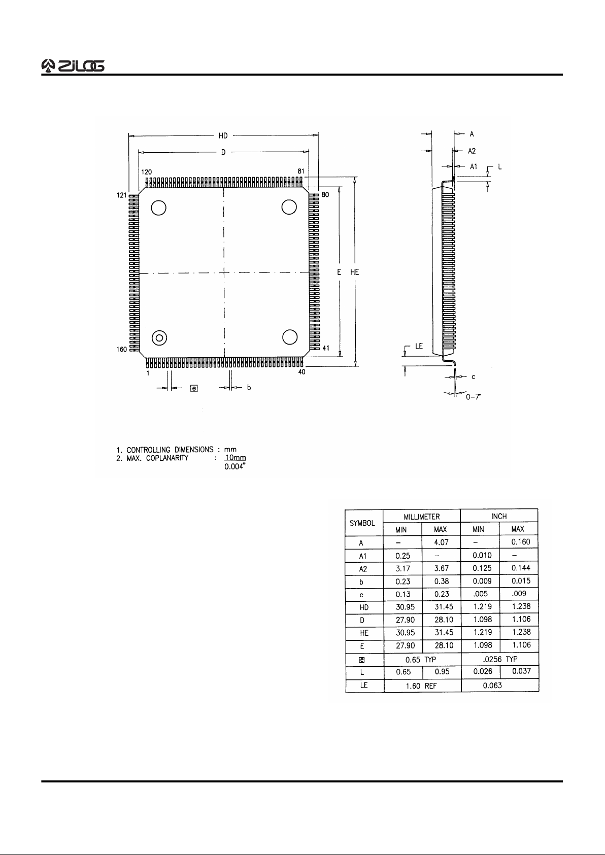
PACKAGE INFORMATION
160-Pin QFP Package Diagram
Page 30
Z89340
Digital Wavetable Engine
1-30 P R E L I M I N A R Y DS96DSP0201
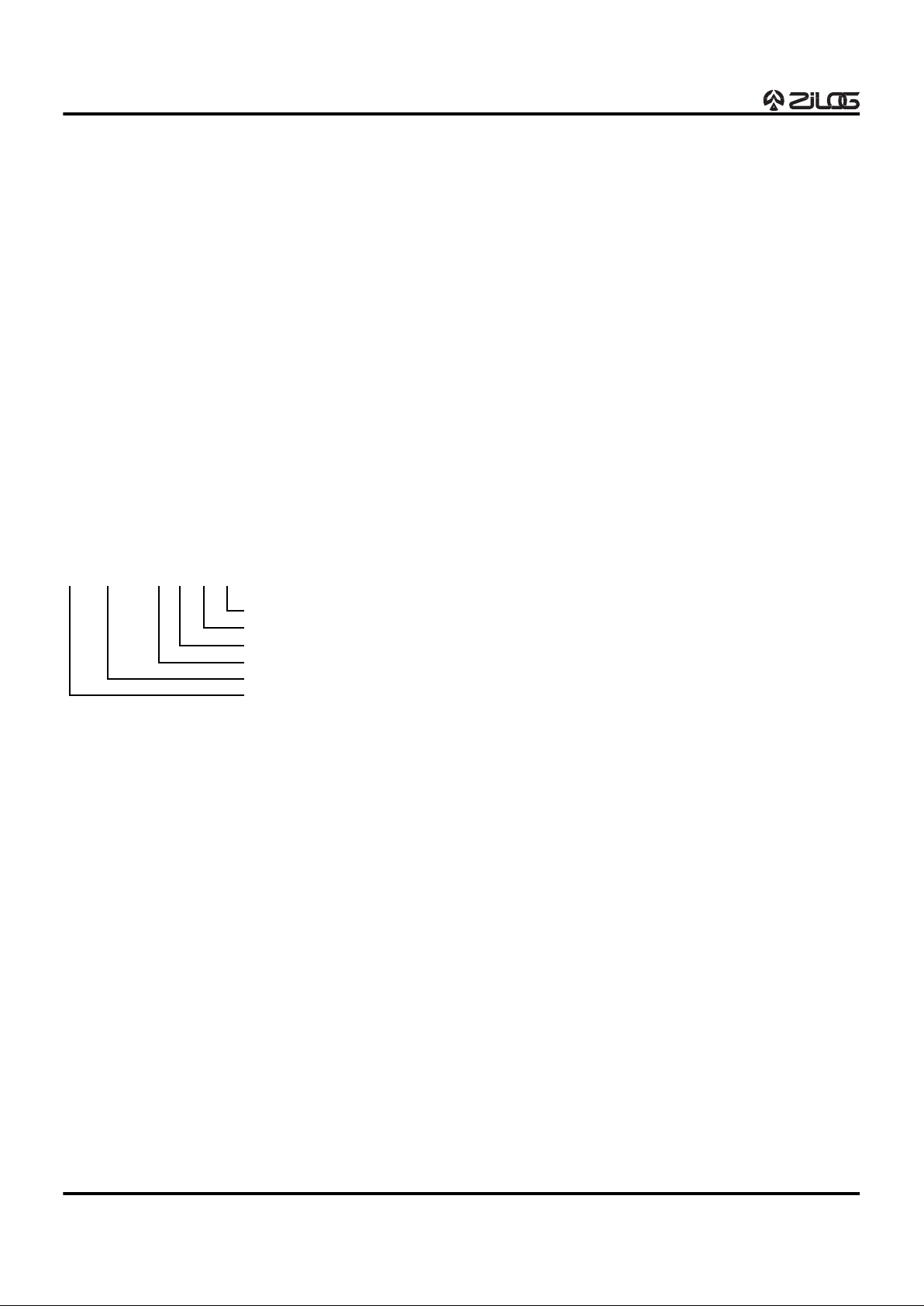
ORDERING INFORMATION
Z89340
50 MHz
160-Pin QFP
Z8934050FSC
For fast results, contact your local Zilog sales office for assistance in ordering the part desired.
Package
F = Quad Flat Pack (QFP)
Temperature
S = 0°C to +70°C
Speed
50 = 50 MHz
Environmental
C = Plastic Standard
Example:
Z 889340 50 F S C is a Z89340, 50 MHz, QFP, 0°C to +70°C, Plastic Standard Flow
Environmental Flow
Temperature
Package
Speed
Product Number
Zilog Prefix
 Loading...