

Page 1
Z6...
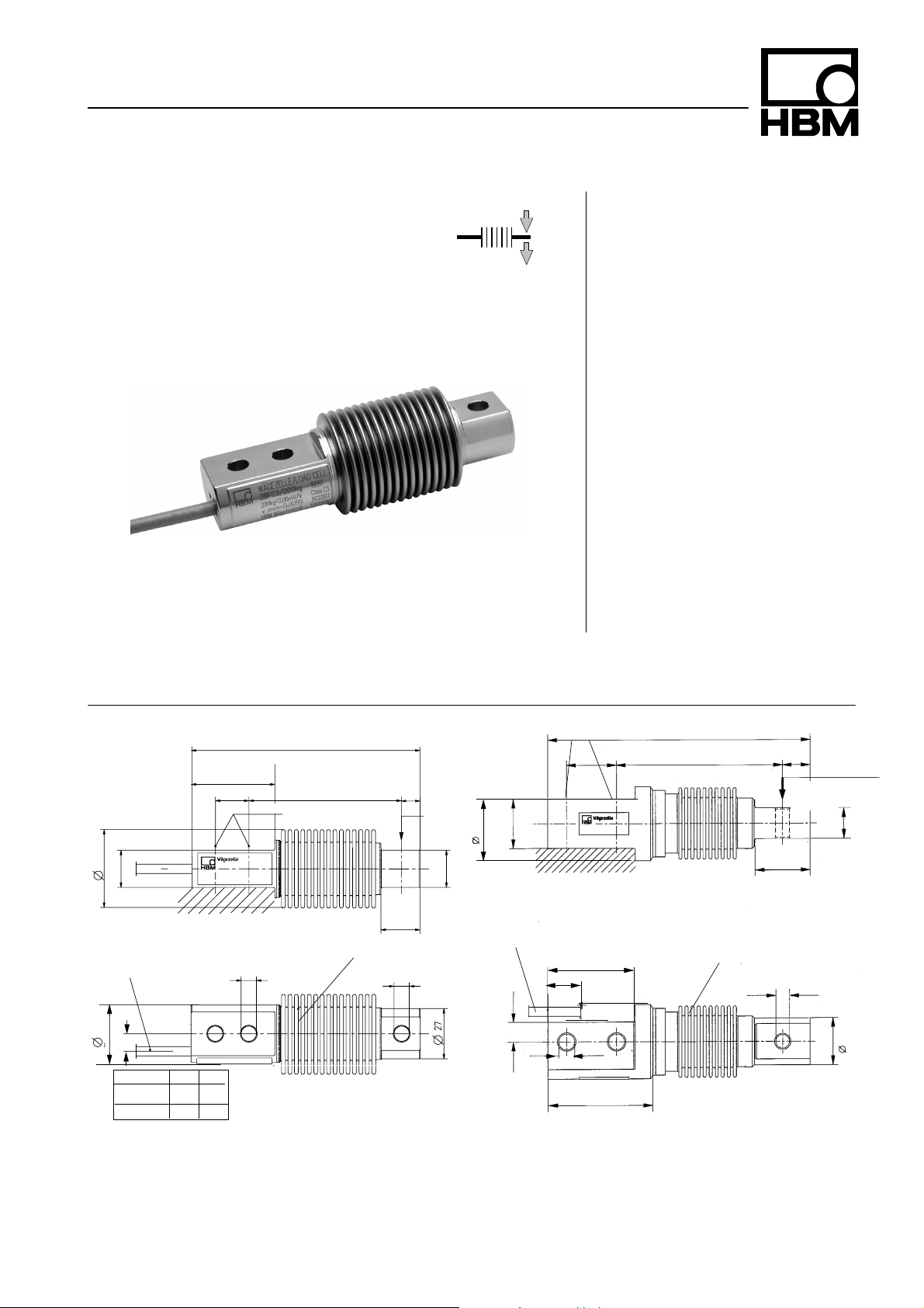
Load cell
Dimension (in mm; 1mm = 0,03937 inches)
Z6; Max. capacities 5kg...500kg
123
45
18
82
Fixing
10
Load
introd.
Max. capacities
5kg...1t
Z6; Max. capacity 1t
40
60
Special features
• Welded on metal bellow
• Load cells and mounting aids
entirely made from stainless
material
• Complies with OIML R60
regulations up to 6000d
• Six-wire circuit
• Optimized for parallel
connection with corner-preadjustment
• Meets today EMC/ESD
requirements according to
EN 45501
• Available option:
Explosion p roof version
EEx ib IIC T4
Fixing
40
210
133±0,1
22±0,1
Load
introd.
25
42
20
Cable: 3m, ∅ 5.4mm, 6
cores screened, screen
connected to housing
31
9,9
AB
5...200kg 8.2 8.2
500kg 10.5 11.1
20
Cable: 3m, ∅ 5.4mm,
21
A
Metal bellow
B
6 cores, screened,
screen connected to
housing
34
15
13
70
Metal bellow
84
44
11, 1
+0,1
-- 0 , 1
38
Data sheet D.Z6.0e
Page 2
Technical data
Typ e Z6FD1 Z6FC3 Z6FC4 Z6FC6
Accuracy class according to OIML R 60
Maximal numbers of load cell verif. intervals (n
Max. capacity (E
) kg 5; 10; 20; 50;
max
LC
)
D1
1000
100; 200;
C3
3000
10; 20; 50;
100; 200;
C4
4000
20; 50; 100;
200;
6000
50;100;200;
500 500 500
t 1 1
Minimum load cell verification interval (v
) %ofC
min
n
0.0360 0.0090 0.0066
Sensitivity (Cn) mV/V 2
Tolerance on sensitivity % <+1;--0.1 <+0.05
Temperature effect on sensitivity (TKC)
Temperature effect on zero balance (TK0) %of
Hysteresis error (dhy)
1)
(d
)
lin
1)
1)
%of
C
/10K
n
<+0.0500 <+0.0080 <+0.0070 <+0.0040
<+0.0500 <+0.0125 <+0.0093 <+0.0093
C
/10K
n
% <+0.0500 <+0.0170 <+0.0130 <+0.0080
% <+0.0500 <+0.0180 <+0.0150 <+0.0110
Creep (dDR)in30min. % <+0.0490 <+0.0166 <+0.0125 <+0.0083
Input resistance (RLC)(black--blue) Ω 350 -- 480
Output resistance (R0)(red--white) Ω 356 + 0.2 356 + 0.12
Reference excitation voltage (U
) V 5
ref
Nominal range of excitation voltage (BU) V 0.5...12
Insulation resistance (Ris) GΩ >5
Nominal temperature range (BT)
Service temperature range (Btu)
Storage temperature range (Btl)
Safe load limit (EL) %ofE
Breaking load (Ed) %ofE
oC[o
F] --10...+40 [15...+105]
oC[o
F] --30...+70 [--20...+160]
oC[o
F] --50...+85 [--60...+185]
max
max
150
300
Max. capacity kg 5 10 20 50 100 200 500 1000
Permissible dynamic load (F
(vibration amplitude according to DIN 50100)
Deflection at max. load, (s
)
srel
) approx. (±15%) mm 0.24 0.3 0.29 0.27 0.31 0.39 0.6 0.55
nom
%ofE
100 100 100 100 100 100 70 100
max
Weight (G), approx. kg 0.5 0.5 0.5 0.5 0.5 0.5 0.5 2.3
Protection class (IP) acc. to EN60529 (IEC529) IP 67 (more rigorous test conditions: 100hat 1m Water column)
Material
Measuring body
Metal below
Cable entrance
Cable sheath
stainless steel
stainless steel
stainless steel / Neoprene
PVC
Optionally Explosion proof version (EEx ib IIC T4) PTB-no. EX-90.C.2094
1)
The data for deviation of linearity, hysteresis and temperature effect on sensitivity are typical values. The sum of these data meets the
requirementsaccordingtoOIMLR60.
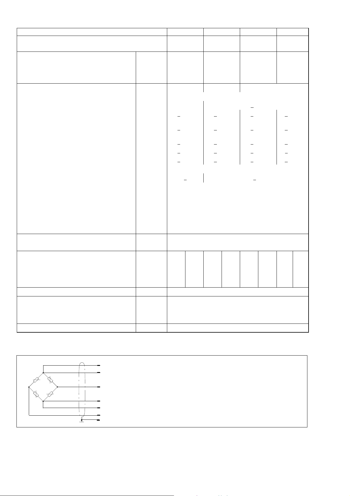
Wiring code
C6
(gray) Sense (--)
(black) Excitation (--)
(white) Signal (+)
(blue) Excitation (+)
(green) Sense (+)
(red) Signal (--)
(yellow) Shield, connected with housing
Page 3

Mounting aids (Dimensions in mm; 1mm = 0.03937 inches)
Note:
All mounting aids are made from stainless material. The ZEL rubber parts are made from chloroprene caoutchouc.
ZGWR Knuckle eye (maintenance-free)
for max. capacities of 5kg...1t
Screw and washer are
included in the scope of
supply
Max.
capacity
5kg...200kg Z6/200kg/ZGWR 16 8
500kg/1t Z6/1t/ZGWR 20 10
Max.
capacity
ZGWR Knuckle
eye
ZRR Fold-back
arm
A B D F G H J K L M SW W Z
D E1E2F1F2G
Screw and washer are
included in the scope of
supply
H7
24 36 48 9 12.5 16 5 M8 14 12 46
H7
28 43 57 10.5 15 19 6,5 M10 17 14 53/55,5
G
1
ZRR Fo ld-back arm
for max. capacities of 5kg...200kg
2
H M
1
M
2
a b Width
5kg...200kg Z6/200kg/ZRR 16 30 30 65 85 46 77 M8 M8x30 M8x30 80+1.1 123 15
ZEL Elastomer bearing
for m ax. capacities of
ZEL Elastomer bearing
for m ax.capacity of 1t
5kg...200kg
A
C
Screws turned
o
by 35
E
Correct mounting position of the elastomer bearing
for m ax. capacity of 500kg
C
D
E
Screws turned
by 35
Max.
capacity
L
H
o
ZEL Elastomer
bearing
Z6/200kg/ZEL
A
Z6/1t/ZEL
F
B
A B C D E F G H L M N P R F
5kg...200kg Z6/200kg/ZEL 75 M12 12 40 79± 1.3 18.5 M8 SW17 -- -- -- -- -- 163 3
500kg Z6/1t/ZEL 80 M10 10 39
1t Z6/1t/ZEL 80 M10 10 39
FR= restoring force in N for s = 1mm S
= max. lateral displacement of load introduction loaded with rated capacity
max
105
117
+2.1
-- 2. 2
+2.1
-2.2
26 -- SW27 20 120 100 9 60 400 4,5
26 -- SW27 20 120 100 9 60 400 4.5
D
L
H
B
Z6/1t/ZEL
F
R
[N]
Smax
[mm]
Page 4

Mounting aids continued
ZPL Pendle bearing
for max. capacities of 5kg...1t
Max.
capacity
5kg...200kg Z6/200kg/ZPL 20
500kg Z6/200kg/ZPL 20
1t Z17/2t/ZPL 30
FR= restoring force for s = 1mm S
ZPL Pendle bea-
ring
ZK Cone and c onical pan for
max. capacities of 5kg...1t
C D
45
-0.2
45
-0.2
60
-0.1
= max. lateral displacement of load introduction
max
Conical pan 90
Cone point 60
H
1
89
89
126.5
4
+0.6
-0.8
+0.6
-0.8
M O T E F1H U FR[% of
M8 30 6.5 17 9 20
M8 30 6.5 17 9 20
M10 46 8 22 14 40
o
o
ZPL
maximum inclination of 3
2 dust-proof protection rings
included with ZPL
D10
20
D10
20
D10
30
X
o
applied
load ]
2.8 3.5
2.8 3.5
2 7.5
Smax
[mm]
Max. capacity
5kg...200kg Z6/200kg/ZK 15 16 21 8.1
500kg Z6/1t/ZK 18 24 32 11
1t Z6/1t/ZK 18 24 32 11
ZK Cone and conical pan C D E U X
Load foot ZFM 8
formax.capacitiesof<
Hottinger Baldwin Messtechnik GmbH
Im Tiefen See 45, D--64293 Darmstadt, Germany
Tel.: +49 (0)6151 / 803 0; Fax: +49 (0)6151 / 803 9 100
www.hbm.com; e--mail: support@hbm.com
200kg
Modifications reserved.
All details describe our products in
general form. They are not to be
understood as express warranty and do
not constitute any liability whatsoever.
-0.05
-0.05
-0.05
26
34
36.5
wt 03.01 -- (pdf)
 Loading...