

YTD439
ISTU
ISDN BRI controller for Terminal Equipment with built-in DSU
❑ Abstract
YTD439 is a LSI that integrates in a single chip all the communication functions that are
necessary for constructing an ISDN terminal with a built-in DSU. The functions of both the DSU
(U reference point) and terminal (S/T reference point) are packed into the 100-pin SQFP chip
allowing miniaturization of the terminal equipment.
YTD439 has a built-in TD switch function that is necessary for controlling the connection of the
B-channel data. By connecting an external CPU, memory, and CODEC, a terminal with a built-in
DSU can be configured. In addition, YTD439 has a function that reduces the power consumption
by stopping the functions of unused blocks. This is effective for battery-driven terminals.
❍ Features
DSU block
• Conforms to TTC Standards JT-I430 and JT-G961.
• LT (line termination) function and CT (circuit termination) function.
• DSU can be disconnected.
S/T reference point driver/receiver block
• Transition to the sleep state possible by setting an I/O register.
CPU interface block
• 8-bit or 16-bit data bus selectable.
• I/O access through registers.
YTD439 CATALOG
CATALOG No.:4TD439A2
2001.1

Layer 1 control block
• Frame assembling and disassembling function.
• I430 TTL output pin
Layer 2 control block
• Built-in LAPD protocol (supports four links).
• Call control and D-channel packet function.
Layer 3 interface block
• Message exchange through I/O access (large 1088-byte FIFO).
B channel HDLC controller
• Supports CRC-CCITT and CRC-32.
• 128k/64k/56k rate adaption
B channel transparent
• Supports PIAFS 64k/32k.
• Flexible rate adaption function.
B channel DATA FIFO
• Transmission and reception: 128-byte FIFO × 2 channels.
TD switch
• Switch circuit for 8 channels of B channel data.
• 512 k to 2,048 kHz PCM highway.
Others
• Terminal block can be disconnected. Power can be cut off.
• Terminal block sleep mode.
• Power supply to the analog block: +5 V.
Power supply to the digital block: +5 V or 3.3 V.
• 5 V tolerant I/O pin
• 100-pin SQFP.
❍ Applications
• Terminal adapter
• Remote router
• ISDN telephone
• ISDN home telephone
• ISDN Facsimile
- 2 -
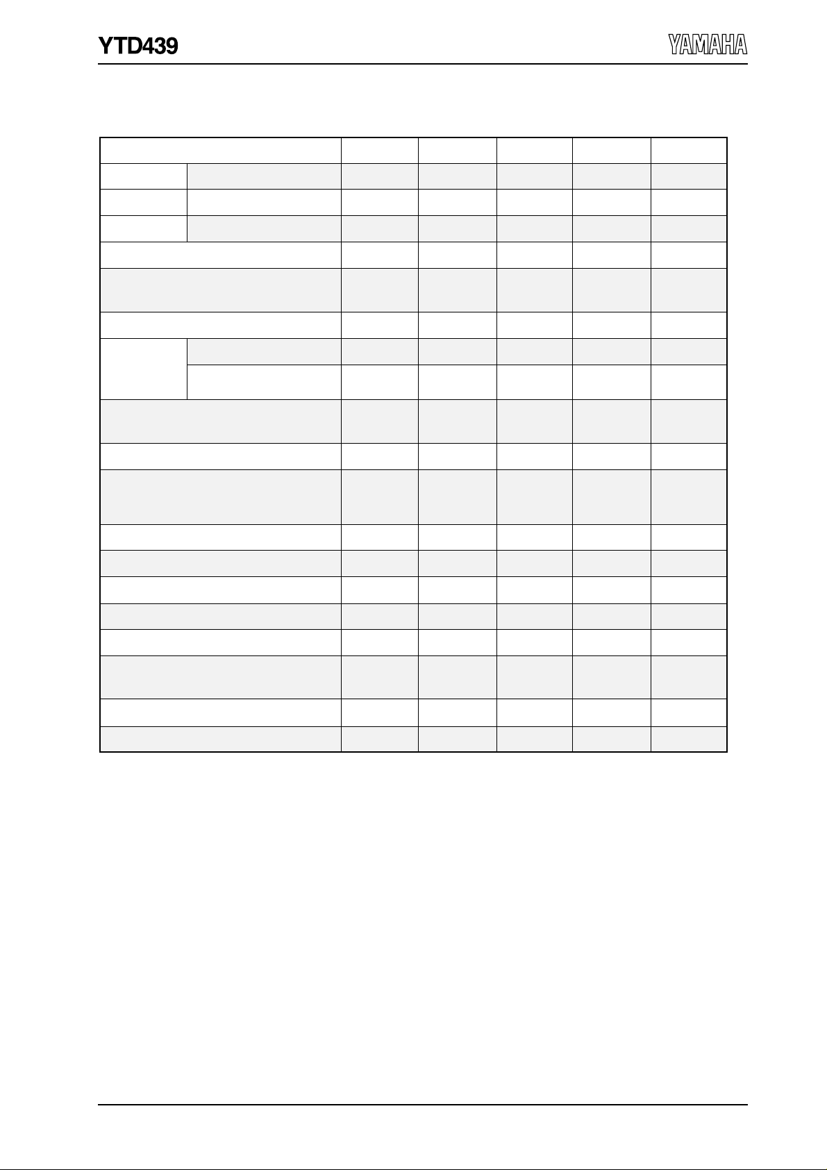
❍ Functional Comparison of YAMAHA ISDN LSIs
Function YTD428YTD421
DSU Function
Layer 1
Layer 2
ETSI
ETS 300 012, ETS 300 125
North American Switches
National ISDN-1/2, AT&T 5ESS,
Nortel DMS-100
S/T Ref. Point Analog Driver/Receiver
Maximum D
Channel Links
D Channel Layer 3 Data Transfer Method
HDLC Controller for B Channel Data
B Channel Data Transfer Method
B Channel Internal Clock Mode (kHz)
TTC Standard
TTC Standard
Circuit switching
Dch Packet Switching
(Teleaction communication)
JT-I430
JT-Q920
JT-Q921
1993 edition
1997 edition
1993 edition
√√
YTD423 YTD436 YTD439
1997 editionTTC Standard JT-G961
1993 edition 1997 edition 1997 edition
1993 edition
1993 edition
1998 edition
1993 edition
1998 edition
√√
√
External
[YTD421]
2
DMA Transfer
or
I/O Transfer
√√
DMA Transfer
or
I/O Transfer
√
√√
222
2
(2)
DMA Transfer
or
I/O Transfer
External
DMA Transfer
or
I/O Transfer
(Note 1)
32, 56, 6432, 56, 64
I/O Transfer
I/O Transfer
2
(2)
B Channel External Clock Mode
TD Switch
Clock Output Function for CPU
Signal Output Function for Testing
Power Supply (V)
5-V Tolerant I/O pin
Package
Note 1:DMA transfer: Request function only
I/O transfer: 4-byte FIFO
Note 2:Digital power supply only
+5
or
+3.3 (Note 2)
+5 +5
100-pin SQFP 100-pin SQFP 100-pin SQFP100-pin SQFP20-pin SSOP
√√√
√
√√√
√√
√
+5
or
+3.3 (Note 2)
+5
or
+3.3 (Note 2)
√
- 3 -
❑ Block Diagram
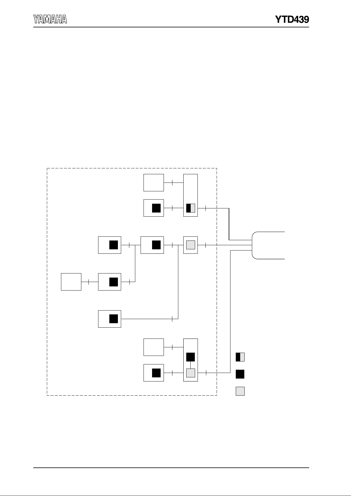
❍ User-Network Interface Block Diagram
YTD439 is best-suited for applications in terminal equipment with built-in DSU (TA, TE1)
such as terminal adapters and remote routers with built-in DSUs.
YTD439 contains a DSU function, which is necessary between the ISDN switch and the usernetwork interface, and layer 1 and layer 2 functions, which are required of ISDN system
equipment. By adding minimal peripheral parts such as microprocessor and CODEC, terminal
equipment can be optimally configured.
R
TE2
(Non-ISDN
terminal)
User's premises
TE2
TE1
SU
TE1
(ISDN terminal)
RS
TA
(Terminal adapter)
TE1
NT2
(PBX, etc.)
TE2
TE1
S/T
TA with
built-in DSU
T
(DSU)
S/T
R
S/T
TA with
built-in DSU
ISDN
Network
NT1
YTD439
U
YTD436 or
YTD423 + YTD421
YTD428 (DSU)
- 4 -
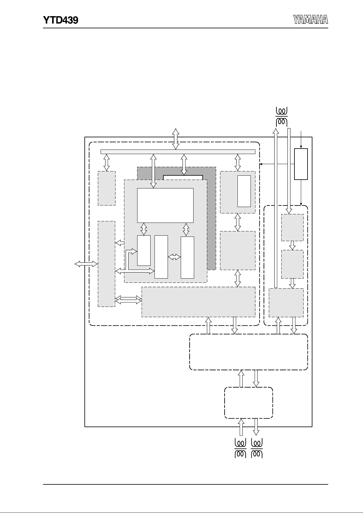
❍ Internal Block Diagram
Rate adaption
block
Transparent
PIAFS
FIFO
(1088 byte)
HDLC
controller
64k × 2
16k
B channel
data
FIFO
(128 byte × 2)
Control
I/O register
Layer 1
control
block
Terminal
block
Layer 2 control
block
(LAPD)
Circuit
termination
block
Line
termination
block
U ref.
point I/F
Layer 3 I/F block
T ref.
point
connection
control
block
DSU block
B channel data control block (CH-A)
B channel connection section
TD switch (8ch)
B channel data control block (CH-B)
Internal bus
B channel PCM highway I/F (CODEC, etc)
(512 k to 2,048 kHz )
U ref. point
15.36 MHz
S/T ref.
point
CPU I/F
Programmable I/O
S/T ref.
point
driver/
receiver
block
Clock
generator
D channel
B1/B2
channel
- 5 -

❑ Pin Assignments
D12
DV
DD
D11
D10
D9
D8
DV
D7
D6
D5
D4
D3
D2
D1
D0
/CS
/WR,R/W
/RD,/AS
/INT
DV
HW_OUT
HW_IN
SYNC_OUT
SYNC_IN
EXTCLK
D13
50
51
2
52
53
54
55
56
57
SS
58
59
60
61
62
63
64
65
66
67
68
69
70
SS
71
72
73
74
75
767778798081828384858687888990919293949596979899100
D14
49
D15
48
/UBE
/LBE
46
47
A1
45
SS
80/68
A2
44
A3
43
42
/RST_NT
DV
/RST_TE
39
40
41
YTD439-S
100pin SQFP
REV
38
NOR
37
1
DD
DV
36
CRD
35
SS
DV
34
CNL
33
LPM3
LP2A
31
32
LPSW
UDP1
29
30
UDP0
UDM1
27
28
UDM0
26
25
24
23
22
21
20
19
18
17
16
15
14
13
12
11
10
9
8
7
6
5
4
3
2
1
ATEI
ATEO
VRB
VRT
RUC
AV
DD
AV
SS
RXU1
SGR
RXU2
SGA
AV
DD
RXS
SGB
SGBP
AV
SS
LI1
CX2
LI2
LICT
CX1
AV
SS
LO1
LO2
RX
1
1
1
1
2
- 6 -
CL8K
CL512K
SS
DV
CL4K
2
DD
DV
CLKOUT
/WAKEUP
INF4
PDOWN
CL400,RM
PDET
VDSEL
POWM
LTD_TE
HTD_TE
1
DD
DV
X2
X1
SS
DV
TSMP
LPSEL
NTSEL
/TEST2
2
DD
AV
/TEST1

❑ Overview of Functions
❍ DSU Block
The DSU section achieves DSU functions of subscriber line interface (two-wire time
compression multiplexing operation) and the user-network interface (digital four-wire time
division full-duplex operation) for ISDN. The electrical characteristics conforming to TTC
Standard JT-G961 is achieved.
Line Termination Block (LT Block)
The line termination section provides the √f equalization that compensates for the line
loss and amplitude distortion and the bridged tap equalization that compensates for
signal distortion.
Circuit Termination Block (CT Block)
The circuit termination provides the following functions:
• U/T reference point rate adaption and frame assembling and disassembling
• State transition control
• U reference point driver circuit control
• T reference point reception timing control
• Loopback control (loopback 2 and loopback C for maintenance and testing)
❍ S/T Reference Point Driver/Receiver Block
By connecting S/T reference point transformers, the electrical characteristics conforming to
TTC Standard JT-I430 is achieved. YTD439 normally operates in the DSU mode. However, if
the DSU function is disconnected, YTD439 switches to the terminal mode and operates as a
S/T reference point terminal LSI.
❍ T Reference Point Connection Control Block
When the DSU block is disconnected or when the driver/receiver functions are disabled, the
input/output signal of JT-I430 is switched within this control block. In addition, when
disconnecting the power to the terminal block or the S/T reference point driver/receiver
block, this block disconnects the signal between the DSU block and the block that is disabled.
- 7 -

❍ Terminal Block
Layer 1 control block
The Layer 1 control block provides the Layer 1 functions conforming to JT-I430.
It automatically controls the Layer 1 state according to (1) the phantom power detection
from the network, (2) the instruction from the host processor and (3) the transaction of
INFO signals and notifies the state change to the host processor. The priority/collision
control block monitors the collision conditions and puts priority on D channel data access
so that each terminal can access the data fairly.
Layer 2 control block
The Layer 2 control block provides the Layer 2 functions (LAP-D protocol) conforming to
JT-Q920 and JT-Q921.
YTD439 can establish total of four data links, two data links for circuit switching and two
data links for D channel packet switching/teleaction communications. It supports the
LAP-D frame assembly and disassembly, the SAPI and TEI address control, the LAP-D
sequence control and flow control for each data link. More specifically, when the YTD439
accepts the data link establishment request from the host processor (Layer 3) in order to
initiate a call or accept an incoming call, the YTD439 activates Layer 1, initiates the TEI
assignment procedure (if necessary), and establishes the data link, thereby enabling the
exchange of layer 3 messages. Later, the YTD439 releases the data link according to the
data link release request from the host processor or the network.
Since both automatic and non-automatic TEI assignment are supported, VC/PVC can be
implemented for packet switching.
Layer 3 Interface Block
The interface between Layer 2 (YTD439) and Layer 3 (host processor) is a logic interface
supporting primitives. The command/status primitives consisting of data up to 8 bytes
are exchanged by writing to or reading from the YTD439 I/O registers to control the data
link.
I frames or UI frames containing Layer 3 messages are transferred using I/O transfer
through the large dedicated FIFO.
B Channel Data Control Block
The B channel data control block consists of two control blocks with the same
functionality for CH-A and CH-B to support the two B channels, B1 and B2. Each B
channel data control block has a HDLC controller block and a transparent block, and the
B channel data FIFO connects to one of the blocks.
You can select the speeds of 128 k, 64 k, or 56 kHz for the HDLC controller block. The
HDLC block supports CRC-CCITT, CRC-32, and no CRC. By activating the HDLC
controller block, protocols such as PPP is also supported.
The transparent block carries out serial-to-parallel conversion on the B channel data and
expands the data in the FIFO. This allows the host processor to check the B channel data
that is received from the line. It also allows transmission of DTMF signals, voice
messages, and other signals to the line by the host processor writing parallel data to the
FIFO. This block also has a flexible rate adaption function that allows the use of protocols
such as V110.
In addition, the transparent block also supports PIAFS64k and PIAFS32k. By following the
commands from the host processor, this block carries out necessary tasks for PIAFS such
as I460 rate adaption, SYNC pattern detection, automatic bit adjustment of 8-bit
boundaries.
- 8 -

TD Switch Block
The TD switch block consists of the time-division switch. It allows the replacement of
data of each channel on the PCM highway. By using the TD switch, the switch control of
B channel data can be facilitated on terminals with multi-functionality such as
extensions, three-way calls, and holding tone.
YTD439 supports 512 kHz to 2,048 kHz PCM highway and can perform switching on 8
channels. You can specify which output channels to connect the 8 channels of input
through the I/O register. One-to-one connection and one-to-multi-point connections are
supported.
The B channel data control block and the layer 1 control block (B channel data) are
connected to the PCM highway internally in the YTD439, and two channels are used by
each. The remaining four channels are connected to the PCM highway pins and allows
connection to arbitrary channels such as an external CODEC.
Input PCM Highway
SYNC_IN pin
(8 kHz)
HW_IN pin
(512 k - 2,048 kHz)
Time
slot 0
Time
slot 1
Time
slot 2
Time
slot 3
Time
slot 4
Time
slot n-1
Time
slot n
n:7 (Min.) - 31 (Max.)
TD switch block
TDSW input
REGX5a-h
TDSW output
B-ch data control block
(CH-A) (CH-B)
Layer 1 control
block
(B1) (B2)
CHI_0 CHI_1 CHI_2 CHI_3 CHI_4 CHI_5 CHI_6 CHI_7
CHO_0 CHO_1 CHO_2 CHO_3 CHO_4 CHO_5 CHO_6 CHO_7
B-ch data control block
(CH-A) (CH-B)
Layer 1 control
block
(B1) (B2)
REG1
REG1
Output PCM Highway
HW_OUT pin
(512 k - 2,048 kHz)
SYNC_OUT pin
(8 kHz)
Time
slot 0
Time
slot 1
Time
slot 2
Time
slot 3
Time
slot 4
Time
slot n-1
Time
slot n
n:7 (Min.) - 31 (Max.)
- 9 -

The data path in the TD Switch Block diagram is set assuming the following application
example.
Voice call and voice monitor using the B1 channel
B1 channel (downward) → Output PCM highway time slot 0 : CHI_6 → CHO_0
→ B channel data control block (CH-A) : CHI_6 → CHO_4
B1 channel (upward) ← Input PCM highway time slot 0 : CHO_6 ← CHI_0
Data communication using the B2 channel
B2 channel (downward) → B channel data control block (CH-B) : CHI_7 → CHO_5
B2 channel (upward) ← B channel data control block (CH-B) : CHO_7 ← CHI_5
- 10 -

❑ Electrical Characteristics
❍ Absolute Maximum Ratings
Parameter Symbol
Supply voltage
Input voltage
Storage temperature
AVDD1 V
DD
2
AV
DV
DD
1
DV
DD
2
AV
IN
1
AV
IN
2
DV
IN
1
DV
IN
2
T
stg
Min. Max.
AV
AV
6.0
6.0
5.7
5.7
DD
1 + 0.3
DD
2 + 0.3
5.75
5.75
125
- 0.3
- 0.3
- 0.3
- 0.3
- 0.3
- 0.3
- 0.3
- 0.3
- 50
(Based on AVSS1 = AVSS2 = DVSS = 0.0 V)
❍ Recommended Operating Conditions
Parameter Symbol
Supply voltage
Operating Temperature
AVDD1 V
DD2
AV
DV
DD1
DD2
DV
DV
DD2
T
op
Condition
Note
Note 5.254.75 V
VDSEL = "H"
VDSEL = "L"
Unit
V
V
V
V
V
V
V
°C
Min. Max.
4.75
4.75
3.0
4.75
3.0
0
5.25
5.25
3.6
5.25
3.6
70
Unit
V
V
V
V
°C
(Based on AVSS1 = AVSS2 = DVSS = 0.0 V)
Note: Select either a 5 V system or a 3.3 V system.
- 11 -

❍ DC Characteristics
U Reference Point Receiver (AVDD1= 5.0 V, Top = 25 °C)
Allowable load impedance
at output
Receive buffer input
impedance
Analog signal reference
voltage
ADC self-bias
Parameter
Symbol
Z
O
Z
i1
V
SG
V
RT
V
RB
Condition
Note 1
Note 2
Note 3
Note 4
Note 5
Min. Max.
30
10
2.45
0.7AV
DD
1 - 0.1
0.3AV
DD
1 - 0.1
Typ.
2.50
0.7AV
0.3AV
DD
DD
1
1
0.7AV
0.3AV
Note 1: Applies to the SGR pin.
Note 2: Applies to the RXU1 and RXU2 pins.
Note 3: Applies to the SGR pin (open).
Note 4: Applies to the VRT pin.
Note 5: Applies to the VRB pin.
DSU Digital Block (DVDD1 = 3.3 ± 0.3 V or 5 V ± 5%, Top = 0 to 70 °C)
2.55
DD
DD
1 + 0.1
1 + 0.1
Unit
kΩ
MΩ
V
V
V
Parameter
High-level input voltage
Low-level input voltage
High-level output voltage
Low-level output voltage
Symbol
V
IH
V
IL
V
OH
V
OL
Condition
Note 1
Note 2
Note 1
Note 2
Note 3
Note 4 AV
Note 3
Min. Max.
0.8DV
DD
1
0.9DV
DD
1
Typ.
DVDD1 - 0.4
DD
1 - 0.4
0.2DV
0.1DV
0.4
DD
DD
1
1
Note 4 0.4
Leakage current
Off-state leak current
I
L
I
LZ
- 10
- 10
10
10
Note 1: Applies to NOR, REV, /RST_NT, POWM, TSMP, LPSEL, NTSEL, /TEST1, /TEST2 pins.
Note 2: Applies to the X1 pin.
Note 3: Applies to LPSW, LP2A, LPM3, CNL, and CRD pins.
Condition: IOH = - 0.4 mA, IOL = 1.2 mA
Note 4: Applies to UDM0, UDM1, UDP0, and UDP1 pins.
Unit
V
V
V
V
V
V
V
V
µA
µA
- 12 -
Condition: AVDD1 = 4.75 to 5.25 V, Top = 25 ºC, IOH = - 0.4 mA, and IOL = 1.2 mA

Terminal Digital Block
a. When DVDD2 = 5 V ± 5% (VDSEL pin = “H” and Top = 0 to 70 °C)
Parameter
High-level TTL input
Low-level TTL input
High-level CMOS input
Low-level CMOS input
High-level output
Low-level output Note 3
Leakage current I
Off-state leakage current
Symbol
V
IH
IL
V
V
IH
V
IL
OH
V
V
OL
V
OL
L
I
LZ
Condition
Note 1
Note 1
Note 2
Note 2
Note 3
Note 4
Note 5
Min. Max.
Typ.
2.2
0.8DVDD2
0.2DV
2.7
- 10
- 10
0.8
DD
2
0.4
0.4
10 µA
10 µA
Note 1: Applies to EXTCLK, SYNC_IN, SYNC_OUT, HW_IN, /RD, /WR, /CS, D15 to D0, /UBE,
/LBE, A3 to A1 pins.
Note 2: Applies to /RST_TE, 80/68, /WAKEUP, PDET, and VDSEL pins.
Note 3: IOH = -0.4 mA, IOL = 1.2 mA
Note 4: When HW_OUT pin is set to open drain. Condition: RL = 500 Ω
Note 5: When pins D15 to D0 are in the input condition (when word access (16 bits) is specified)
and when pins D7 to D0 are in the input condition (before issuing the SYSTEM–
CONFIGURATION–REQUEST command or when byte access is (8 bits) is specified).
Unit
V
V
V
V
V
V
VOpen drain output
b. When DVDD2 = 3.3 V ± 0.3 V (VDSEL pin = “L”, Top = 0 to 70 °C)
Parameter
High-level input 0.8DV
Low-level input
High-level output
Low-level output
Open drain output
Leakage current
Note 1: Applies to EXTCLK, SYNC_IN, SYNC_OUT, HW_IN, /RD, /WR, /CS, D15 to D0, /UBE,
/LBE, A3 to A1, /RST_TE, 80/68, /WAKEUP, PDET, and VDSEL pins.
Note 2: IOH = -0.4 mA, IOL = 1.2 mA
Note 3: When HW_OUT pin is set to open drain. Condition: RL = 500 Ω
Note 4: When pins D15 to D0 are in the input condition (when word access (16 bits) is specified)
and when pins D7 to D0 are in the input condition (before issuing the SYSTEM–
CONFIGURATION–REQUEST command or when byte access is (8 bits) is specified).
Symbol
V
IH
IL
V
V
OH
V
OL
OL
V
L
I
LZ
I
Condition
Note 1
Note 1
Note 2
Note 2
Note 3
Note 4
Min. Max.
DD
DD
2- 0.4
DV
Typ.
2
- 10
- 10
DD
0.2DV
2
0.4
0.4
10 µA
10 µAOff-state leakage current
Unit
V
V
V
V
V
- 13 -

❑ Package Outline
- 14 -

IMPORTANT NOTICE
Yamaha reserves the right to make changes to its Products and to this document
1.
without notice. The information contained in this document has been carefully checked
and is believed to be reliable. However, Yamaha assumes no responsibilities for
inaccuracies and makes no commitment to update or to keep current the information
contained in this document.
These Yamaha Products are designed only for commercial and normal industrial
2.
applications, and are not suitable for other uses, such as medical life support
equipment, nuclear facilities, critical care equipment or any other application the failure
of which could lead to death, personal injury or environmental or property damage. Use
of the Products in any such application is at the customer’s sole risk and expense.
Yamaha assumes no liability for incidental , consequential, or special damages or injury
3.
that may result from misapplication or improper use or operation of the Products.
Yamaha makes no warranty or representation that the Products are subject to
4.
intellectual property license from Yamaha or any third party, and Yamaha makes no
warranty excludes any liability to the Customer or any third party arising from or related
to the Products’ infringement of any third party’s intellectual property rights, including the
patent, copyright, trademark or trade secret rights of any third party.
Examples of use described herein are merely to indicate the characteristics and
5.
performance of Yamaha products. Yamaha assumes no responsibility for any
intellectual property claims or other problems that may result from applications based on
the examples described herein. Yamaha makes no warranty with respect to the
products, express or implied, including, but not limited to the warranties of
merchantability, fitness for a particular use and title.
The specifications of this product are subject to improvement changes without prior notice.
AGENCY
Address inquiries to:
Semiconductor Sales & Marketing Department
Head Office 203, Matsunokijima, Toyooka-mura
Iwata-gun, Shizuoka-ken, 438-0192
Tel. 81-539-62-4918 Fax. 81-539-62-5054
Tokyo Office 2-17-11, Takanawa, Minato-ku,
Tokyo, 108-8568
Tel. 81-3-5488-5431 Fax. 81-3-5488-5088
Osaka Office Namba Tsujimoto Nissei Bldg, 4F
1-13-17, Namba Naka, Naniwa-ku,
Osaka City, Osaka, 556-0011
Tel. 81-6-6633-3690 Fax. 81-6-6633-3691
All rights reserved 2001
 Loading...