

Page 1

XECOM (1) XEISDNB
XEISDNB
2/99
Description
The XEISDNB integrated ISDN Terminal Adapter offers
an easy to use, high performance, component-level solution for equipment designs needing access to ISDN service. The module can directly connect to a host processor
through its on-board serial TTL level interface and link to
the ISDN subscriber line U interface with its integrated
NT1.
The device is designed for the ISDN Basic Rate Interface
(BRI) which consists of two 64 k bps bearer (B) channels
for data or voice and one delta (D) channel for signaling.
The module can provide a full 128k bps synchronous data
channel by combining the two bearer channels.
Alternatively, one 64k bps channel can be dedicated to
data while the other can be made available for analog
phone/fax/modem calls with the addition of the
XEISDNP Analog Telephone (POTS) Equipment Interface. Together these provide the user with a complete
ISDN terminal adapter function in two compact modules.
Built-in ISDN control firmware supports all the functions
necessary for setup and configuration of the terminal
adapter and the ISDN line. Configuration can be accomplished via an extended AT command set, a menu-driven
setup utility, or factory default/user stored configuration
profiles.
The built-in ISDN Monitor firmware has fifteen commands supporting customer program development and
download. The 256Kx16 Flash memory is designed to
support custom control program downloading. By changing a configuration pin the XEISDNB can boot-up from
the ISDN-Monitor or a user developed program
as well as the built-in ISDN control program.
Features
· Small size: 2.75" x 1.38" x 0.42"
· Motorola MC68302 Integrated Multi-protocol Processor with RISC controller. 128K x
16 SRAM, 256K x 16 Flash Memory and
8K x 8 EEPROM included
· ISDN line U interface (integrated NT1) with
2B1Q encoding (ANSI T1.601) for North
American usage
· V.120 rate adaptation, point to point protocol
(PPP), Multi-link PPP, Asynchronous Inverse
Multiplexing (AIM), and synchronous
BONDING protocol
· ISDN control program allows connection
with AT&T 5ESS, Northern Telecom DMS
100 and National ISDN-1 central office
switches
· EIA-232E/V.24 ready serial interface at TTL
levels (RS-232-TTL)
· 300 to 115,200 bps asynchronous, 1200 to
64,000 bps synchronous data rate; up to 128k
bps with BONDING protocol
· Menu-driven and stored configurations
· Control outputs to interface with XEISDNP
Analog Telephone (POTS) Equipment Interface module
· On-board ISDN Monitor supports user program downloading and system debugging
· Jumper configurable memory addressing allows easy change from Development to Application mode (using built-in ISDN control
program or user developed program)
ISDN Terminal Adapter with NT1 and Channel Bonding
Page 2
XECOM (2) XEISDNB
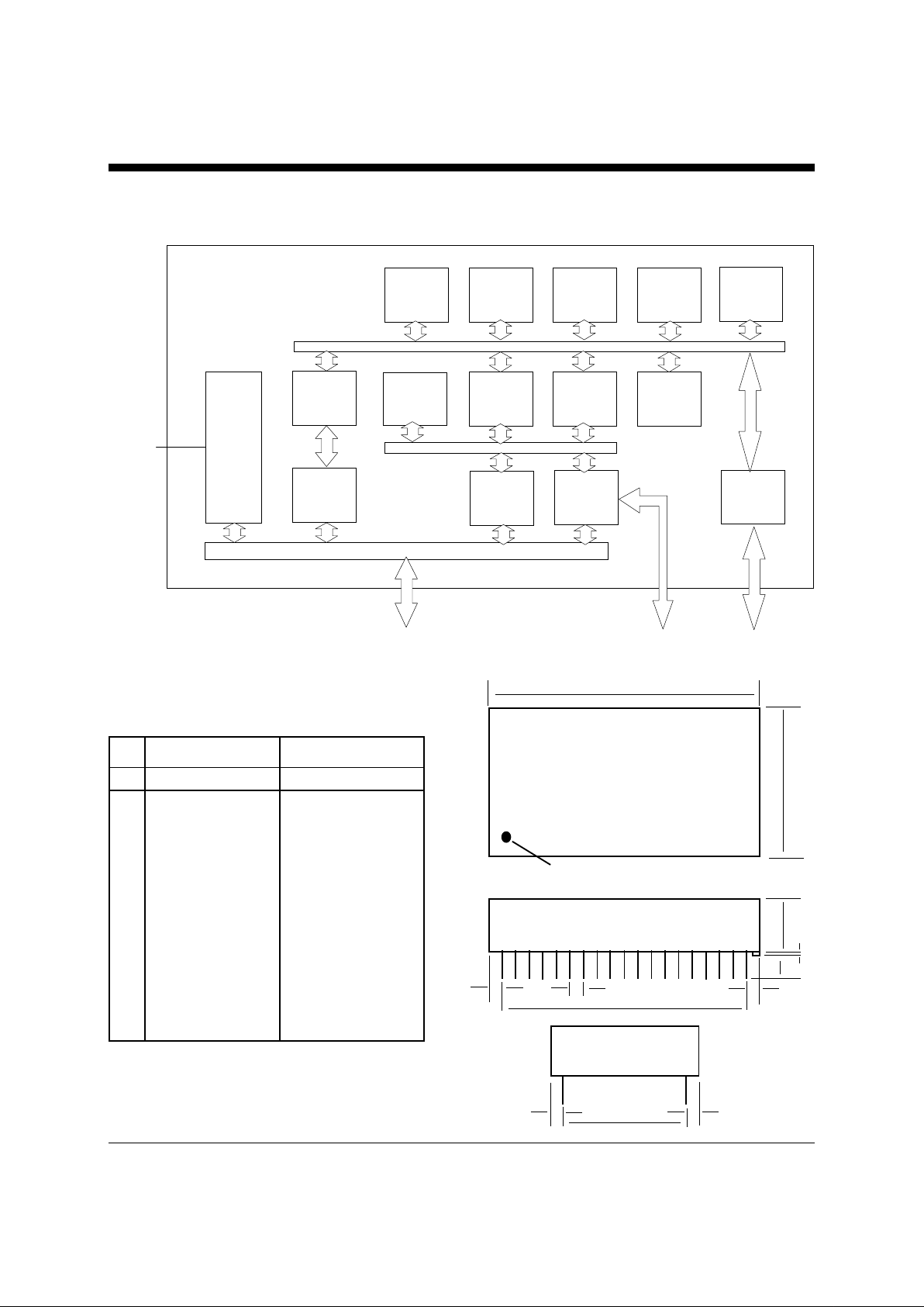
XEIS D N B
DMA
(1)
68000
Core
T imers
(3)
DMA
(6)
512 KB
Flash
memory
1152 Byte
Dual port
RAM
SM Cs (2)
and
SCP
SCCs
(3)
256 KB
SRAM
8 KB
EEPROM
U
Interfac e
I/O p orts
RISC
C ontr oller
POTS Data RS-232 -T TL POTS Control
ISDN
Local
Loop
IDL B U S
SCC
(1)
DMA
(2)
XEISDNB Block Diagram
Mechanical Specifications
INCHES METRIC (MM)
MIN MAX MIN MAX
A 2.740 2.760 69.60 70.10
B 1.370 1.390 34.80 35.31
C 0.420 0.430 10.67 10.92
D 1.190 1.210 30.23 30.73
E 2.290 2.310 58.17 58.67
F 0.125 0.200 3.18 5.08
G 0.080 0.100 2.03 2.54
H 0.215 0.235 5.46 5.97
I 0.090 0.110 2.29 2.79
J 0.020 0.025 0.51 0.64
Denotes Pin 1
A
B
C
FJ
HI H
E
GG
D
Page 3
XECOM (3) XEISDNB
2
6
5
4
3
8
7
12
11
10
9
14
13
18
17
16
15
20
19
24
23
22
21
47
48
43
44
45
46
41
42
37
38
39
40
35
36
31
32
33
34
29
30
25
26
27
28
R
r
R
r
TI
2
TD TTL
D
TOUT2
RD TTL
T
TTL
T
LK TTL
D
R TTL
R
r
RI TTL
R
TBT
M
LK TTL
R
r
D
T
R
r
D
L
i
E
R
r
LK
DTMF RDY
DI
P
R
TRL
RI
E
RT
TRL
D4
D
D7
D
R
r
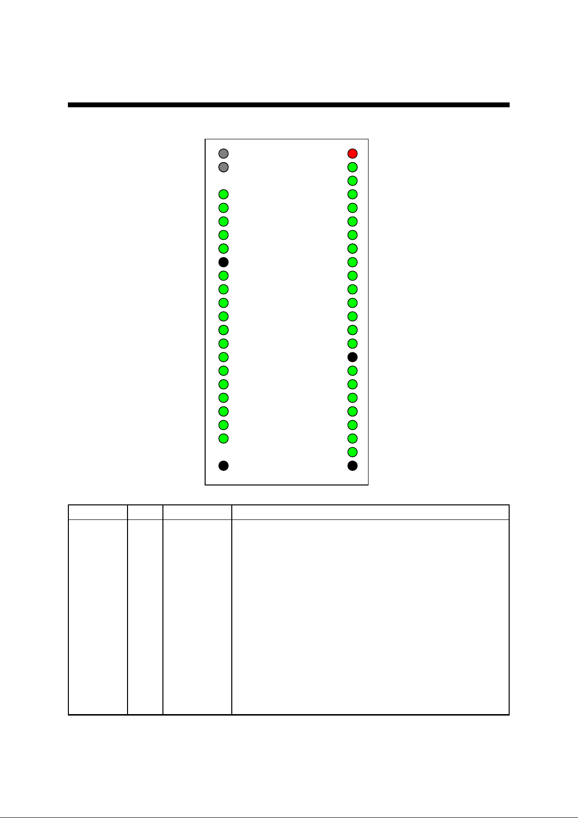
Pin Configuration
Pin Descriptions
Pin Name Pin # Direction Description
TIN1 1 ISDN U transformer primary A
TIN2 2 ISDN U transformer primary B
No Pin 3 N/A No pin
TOUT1 4 ISDN U transformer secondary A
TOUT2 5 ISDN U transformer secondary B
Reserved 6 N/A No user connection allowed
Reserved 7 N/A No user connection allowed
Reserved 8 N/A No user connection allowed
GND 9 Ground Power & signal ground
CFG/SDO 10 Input/Output Configuration setup. See Modes of Operation. When re-pro-
gramming the In-System Programmable (ISP) CPLD, this pin is
used for the cascade connections and should not be pulled low or
high.
TD_TTL 11 Input RS-232C, Transmitted Data, TTL Level
RD_TTL 12 Output RS-232C, Received Data, TTL Level
Reserved
FSX
Page 4

XECOM (4) XEISDNB
RTS_TTL 13 Input RS-232C, Request to Send, TTL Level
CTS_TTL 14 Output RS-232C, Clear to Send, TTL Level
DSR_TTL 15 Output RS-232C, Data Communications Equipment (DCE) Ready, TTL
Level
CD_TTL 16 Output RS-232C, Received Line Signal Detect, TTL Level
TCLK_TTL 17 Output RS-232C, Transmit Clock, TTL Level
Reserved 18 N/A No User Connection Allowed
DTR_TTL 19 Input RS-232C, Data Terminal Ready, TTL Level
RI_TTL 20 Output RS-232C, Ring Indicator, TTL Level
MCLK_TTL 21 Input RS-232C, Master Clock, Transmitter Signal Timing (DTE Source)
RST_BT 22 Input Optional on-board processor Reset button
No Pin 23 N/A No Pin
GND 24 Ground Power & signal ground
Reserved 25 N/A No User Connection Allowed
D7 26 Input Data bus line 7 for CODEC Data
D6 27 Input Data bus line 6 for CODEC Data
D5 28 Input Data bus line 5 for CODEC Data
D4 29 Input Data bus line 4 for CODEC Data
PDI 30 Output CODEC Power Down Control
RT_CTRL 31 Output CODEC Voice Signal Route Control
PWR_CTRL 32 Output POTS Phone Set Power Control
DC_EN 33 Output Enable DC Source for RING generation
RING_EN 34 Output RING Signal Enable for POTS module
DTMF_RDY/SDI 35 Input DTMF Signal Ready from POTS module. When used with the In
System Programmable CPLD, It becomes the SDI
OH/MODE 36 Input Off Hook Signal from POTS module. When used with In System
Programmable CPLD it becomes the Mode Control
SCLK 37 Input SCLK for In System Programmable CPLD
ISP_EN 38 Input In System Programmable CPLD Enable Signal
FSR 39 Output CODEC Frame Sync. Receive
Reserved 40 N/A No User Connection Allowed
Reserved 41 N/A No User Connection Allowed
Reserved 42 N/A No User Connection Allowed
Reserved 43 N/A No User Connection Allowed
FSX 44 Output Frame Synchronization
DIN 45 Input Data In
DOUT 46 Output Data Out
DCL 47 Output Data Clock
+5V 48 Power +5 Volt power supply
Electrical Specifications
ABSOLUTE MAXIMUM RATINGS
Parameter Maximum V alue
Supply Voltage VCC (+5V) +6.5 Volts
DC input voltage (TTL inputs) -0.6 Volts to +6.5 Volts
Storage Temperature Range -25C to +85C
Lead Temperature (soldering, 2 sec/wave) +260C
Operating T emperature Range 0 to 70C
* Exceeding these values may result in permanent damage to the device
Page 5
XECOM (5) XEISDNB
POWER SUPPLY CHARACTERISTICS (Ta = +70C)
Symbol Parameter Min Typ Max Unit Notes
Vcc Supply Voltage 4.75 5.0 5.25 Volts
Icc Vcc Supply Current 200 mA
I/O Characteristics
ISDN U - INTERFACE
Parameter Specification
Line interface ANSI T1.601, 2B1Q encoding, U reference point
(with recommended components)
ISDN Switch Compatibility National ISDN-1, Northern Telecom DMS-100,Lucent 5ESS
B Channel Protocols V.120, PPP, Multi-link PPP, Async inverse multiplexing, BONDING
RS-232-TTL Interface
Parameter Symbol Min Typ Max Unit Notes
Input High Voltage V sub IH 2.0 5.0 Volts
Input Low Voltage V sub IL -0.3 0.8 Volts
Input Leakage Current I sub IL 20 MA
Output High Voltage V sub OH 3.875 Volts Vcc = 5 Volts
Output Low Voltage Vsub OL 0.5 Volts Vcc = 5 Volts
Recommended Components List
Component Qty Value Supplier Part Number Phone Number
Transformer 1 Midcom 671-7834 605-886-4385
Schott 671 46720 615-889-8800
Pulse Engineering PE 68628 619-674-8100
Resistor 2 6 Ohm, ¼ W
Capacitor 1 3300 pF
Connector 1 8 pin (pins 4,5 active) RJ45
Design Considerations
ISDN Capability
Integrated Services Digital Network (ISDN) is a powerful, flexible, high-speed service now available from most local phone service providers in North America, Asia, and Europe. It provides two 64k bps digital bearer channels (B
channels) and one 16k bps signaling channel (D channel) over a single pair of copper wires. Typically the installed
base of subscriber loop wiring is adequate for this service, making ISDN the most cost effective means of delivering
high speed digital dial-up service to homes and businesses.
Because ISDN is a digital service, connection of computer equipment does not require a modem like a conventional
analog line. However a terminal adapter is required to translate the physical signal levels and the protocols of the
Data Terminal Equipment into those of the ISDN lines and switches. External ISDN Terminal Adapters have been
available for some time. The XEISDNB provides a simple means for designers to implement an internal TA function without dedicating an entire board and a significant firmware investment to this purpose.
Page 6

XECOM (6) XEISDNB
Terminal Adapter Function
The XEISDNB integrated ISDN Terminal Adapter Module is designed to provide a compact, simple design solution
for adding ISDN service access to industrial, medical, computer, business, and consumer products which need to
communicate with remote computers or networks at high data rates. Only four passive components must be added
to implement the hardware interface, signaling and protocols for the North American ISDN standard interface to the
local telephone company.
When used alone the XEISDNB module presents a high speed digital data channel to the local host equipment
through an RS-232E-ready (TTL) serial interface. This channel can be configured by the designer or user for high
speed synchronous or asynchronous applications. Async Inverse Multiplexing (AIM) or Multi-link PPP provides up
to 115.2k bps asynchronous throughput. BONDING protocol provides a 128k synchronous channel.
When combined with the XEISDNP Analog Telephone Equipment Interface, the XEISDNB can provide either B
channel ( on the same physical ISDN line) for simultaneous use by an independent analog phone, fax, or modem designed for “Plain Old Telephone Service” (POTS). Thus the user can place voice calls over the same ISDN line as
data calls, and his investment in existing analog phone equipment is preserved.
Page 7
XECOM (7) XEISDNB
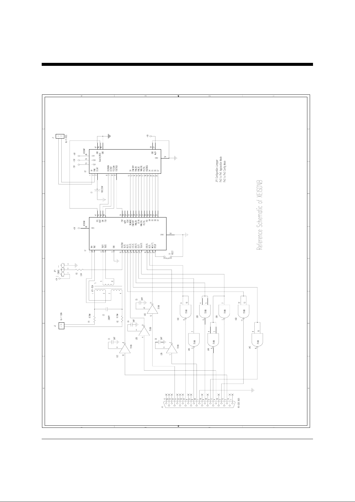
Typical Application Circuit
Page 8

XECOM (8) XEISDNB
Modes of Operation
Application Mode
The normal mode of operation of the XEISDNB is Application Mode. This would typically be the only mode visible to the equipment end user. When the CFG/SDO (pin 10) is pulled high, the XEISDNB module is in the Application mode. The ISDN configuration and control program supplied by Xecom or the equipment designer’s specially developed control program will boot-up upon power-on. In this mode the control program can occupy up to
240K x 16 of the 256K x 16 Flash memory.
Development Mode (ISDN Monitor)
XEISDNB also provides a development tool for designers who wish to write their own firmware control code.
When the CFG/SDO (pin 10) is pulled low, the module will boot-up from the on board ISDN Monitor program. The
xecom ISDN Monitor has fifteen debugging commands including program downloading, memory contents display
and Flash memory operation. The complete command set is listed in the Configuration Guide.
After the designer program has been developed and tested using the ISDN Monitor utility it can be downloaded into
non-volatile Flash memory. The module is then reconfigured to the Application Mode, and the program is ready to
run.
Configuration and Setup
An ISDN telephone line presents a significantly more powerful and complex interface to the user than a standard
analog (POTS) line. Unlike an analog line, the digital ISDN line requires special setup, demultiplexing, and signal
processing to separate its two 64k bps data channels (B channels) and its 16k bps signaling channel (D channel) at
the user interface. In order to establish a connection to an ISDN line, certain parameters must be exchanged between the telephone company switch and the local data communication equipment to initialize the call. It is assumed here that the user has access to an already installed ISDN line and the configuration parameters (Dial Numbers, Service Profile Identifiers, Switch Type, Switch Version, Long Distance Carrier) provided by the phone company for that line. Further information on these parameters is contained in the Configuration Guide.
In addition to the remote switch configuration, the local terminal adapter (TA), like an analog modem, must be set
up properly to operate. There are several parameters which must be set compatibly at the TA and the switch to
specify the exact services to be provided over the line. These parameters will vary with the application. The
XEISDNB implements these functions based on setup information provided by the user. There are three methods
for configuration of the link.
AT Command Configuration
The most basic configuration technique is through AT commands. The user interface is similar to that of an analog
modem with an extended command set. The user communicates this information to the module through the RS232E serial port. A PC running standard VT100 compatible serial communications software is typically used for
this purpose. The AT command set of the XEISDNB is designed to enable configuration and testing for both the remote switch and the terminal adapter.
Page 9

XECOM (9) XEISDNB
Like an analog modem, the XEISDNB operates in two modes: data mode and command mode. In data mode the
device sends all data received at its data ports down the ISDN link. In command mode the TA interprets these inputs as configuration and setup commands and processes them locally. Commands are communicated to the TA via
its RS-232 serial interface from the local host processor. The TA enters command mode upon power-on, any time
the Escape command “+++” is received, or when a call is terminated.
The commands for TA configuration are modeled on the standard set used for analog modems with extensions for
the new ISDN functions. Commands for remote switch configuration and the unique ISDN functions required of
the terminal adapter have been added. The XEISDNB firmware contains an AT Command Help listing which can
be displayed by typing “AT&H” while in command mode. The module will respond with a listing of AT commands
with brief definitions of each. The complete command set listing appears in the Configuration Guide along with examples of configuration profiles for typical applications.
Menu Configuration
The second configuration method uses a group of Setup Menus built into the XEISDNB firmware. These menus
are accessed by entering the AT command “@SETUP” while the module is in Command Mode. Keyboard commands from a PC in VT100 terminal emulation mode allow the user to move through the complete set of configuration choices, enter variable data, and store the results. Operation of the Setup Menus are explained in the Configuration Guide.
Stored Configurations
A complete set of configuration parameters must be in place each time the XEISDNB places a call. However the
current parameters are held in volatile memory and are lost when the host equipment power is interrupted. Also,
once a working configuration has been established for a particular ISDN line, terminal equipment set, and service
type there is no need to change it for each call. To speed up and/or automate the call setup process stored configurations are provided in the XEISDNB.
Two types of stored configurations are provided: factory defaults and user defined configurations. Factory defaults
are stored in Flash memory while user defined sets are stored in EEPROM. The factory default configuration sets
provided represent setups for common applications. Descriptions of these are contained in the Configuration Guide.
There are provisions for two user defined configuration sets. In addition the settings associated with switch parameters are stored and accessed separately to help prevent accidental changes. Extended AT commands are provided
to store and load these configuration sets upon power up or separately. These commands are detailed in the Configuration Guide.
Page 10

XECOM (10) XEISDNB
Terms of Sale
Devices sold by XECOM are covered by the warranty provisions appearing in its Terms of Sale only. XECOM
makes no warranty, express, statutory, implied, or by description regarding the information set forth herein, or
regarding the freedom of the described devices from patent infringement. XECOM makes no warranty of
merchantability or fitness for any purposes. XECOM reserves the right to discontinue production and change
specifications and prices at any time and without notice. This product is intended for use in normal commercial
applications. Applications requiring extended temperature range, unusual environmental requirements, or high
reliability applications, such as military, medical life-support or life-sustaining equipment, are specifically not
recommended without additional processing and authorization by XECOM for such application.
Xecom assumes no responsibility for the use of any circuitry other than circuitry embodied in a Xecom product.
No other circuits, patents, or licenses are implied.
Life Support Policy
Xecom's products are not authorized for use as Critical Components in Life Support Devices or Systems.
Life Support Devices or Systems are devices or systems which, (a) are intended for surgical implant into the body,
or (b) support or sustain life, and whose failure to perform, when properly used in accordance with instructions provided in the labeling, can be reasonably expected to result in significant injury to the user.
A Critical Component is any component of a life support device or system whose failure to perform can be reasonably expected to cause failure of the life support device or system, or to affect its safety or effectiveness.
Copyright, Xecom © 1999
While Xecom, Inc. has made every effort to ensure that the information presented here is accurate, Xecom will not
be liable for any damages arising from errors or omission of fact. Xecom reserves the right to modify specifications
and/or prices without notice. Product mentioned herein are used for identification purposes only and may be trademarks and/or registered trademarks of their respective companies.
Xecom
Incorporated
374 Turquoise Street, Milpitas, CA 95035
Ph:408-945 -6640 Fax:408 -942-1346
Email: [email protected]
 Loading...