

Page 1
XE5614L
Compact 56 KBPS Modem Module for Embedded Applications
October 2000
Description
Xecom's XE5614L is a complete, 56 Kbps modem in a
single component. The XE5614L can be used in throughout North America and Japan. It includes user transferrable FCC Part 68 Registration.
The XE5614L is a complete modem including the DAA.
XE5614L users do not need to add RAM, ROM, Crystals,
low distortion transformer, or switches to complete the
modem design. The user only needs to provide the TTL
level, serial interface and the telephone line connection.
The XE5614L is a full-featured modem. Besides 56 Kbps
data transfer, the XE5614L supports data compression,
error correction and fax transfer. The XE5614L also
includes NVRAM for permanent storage of the modem
configuration.
The XE5614L is pin compatible with Xecom's XE1414L,
and XE3314L modems. This family of modems permits a
simple upgrade path from 14,400 bps to 56,000 bps.
Features
Meets telecom requirements for North America, and
*
Japan: Includes User Transferrable FCC Part 68 Registration
Small Size: 2.75 inches by 1.38 inches by 0.42 inches;
*
Modem Protocols for data transmission from 56 KBPS
*
down to 300 BPS: XEV.90 (56 Kbps), V.34bis, V.34,
V.32bis, V.32, V.22bis, V.22, V.21, Bell 212A and 103;
* Modem Control and Configuration via standard AT
Commands
Fax Protocols: V.17, V.29, V.27ter, and V.21 channel 2
*
Error Correction; V.42, MNP2-4 and MNP10
*
Data Compression; V.42bis and MNP5 provides a
*
maximum effective data rate of 133,400 bps.
Non-Volatile Memory including for storing telephone
*
numbers and modem configuration.
* Standard operating temperature range 0C to 70C.
Extended operating temperature range of -40C to +85C
is availalble.
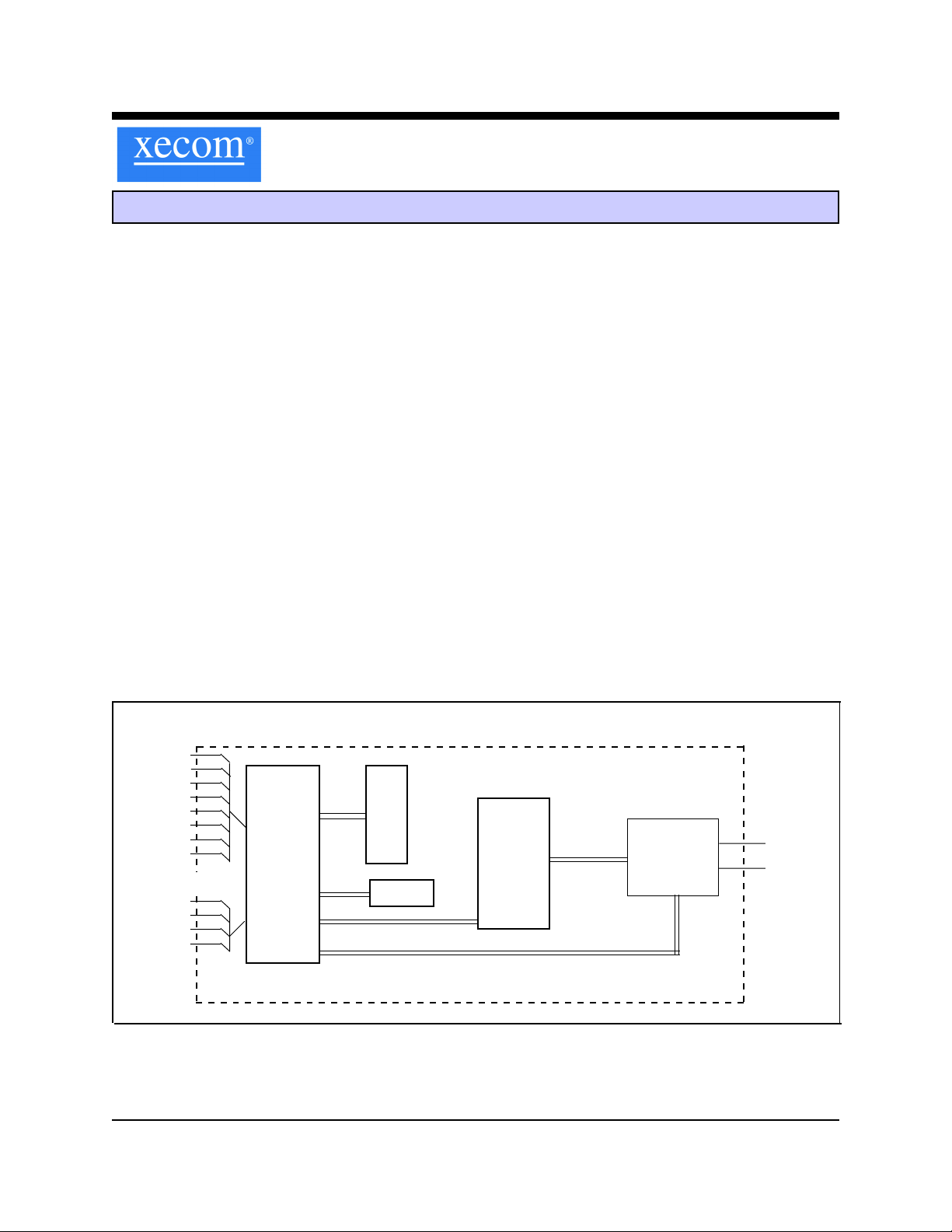
Serial I/O
/DTR
/RTS
/CTS
/DSR
TXD
RXD
/DCD
Auxiliary I/O
RESET
AR
OH
AMP
Modem
Controller
Block Diagram
ROM
NVRAM
Analog
Front
End
DAA
Tip
Ring
XECOM (1) XE5614L
Page 2
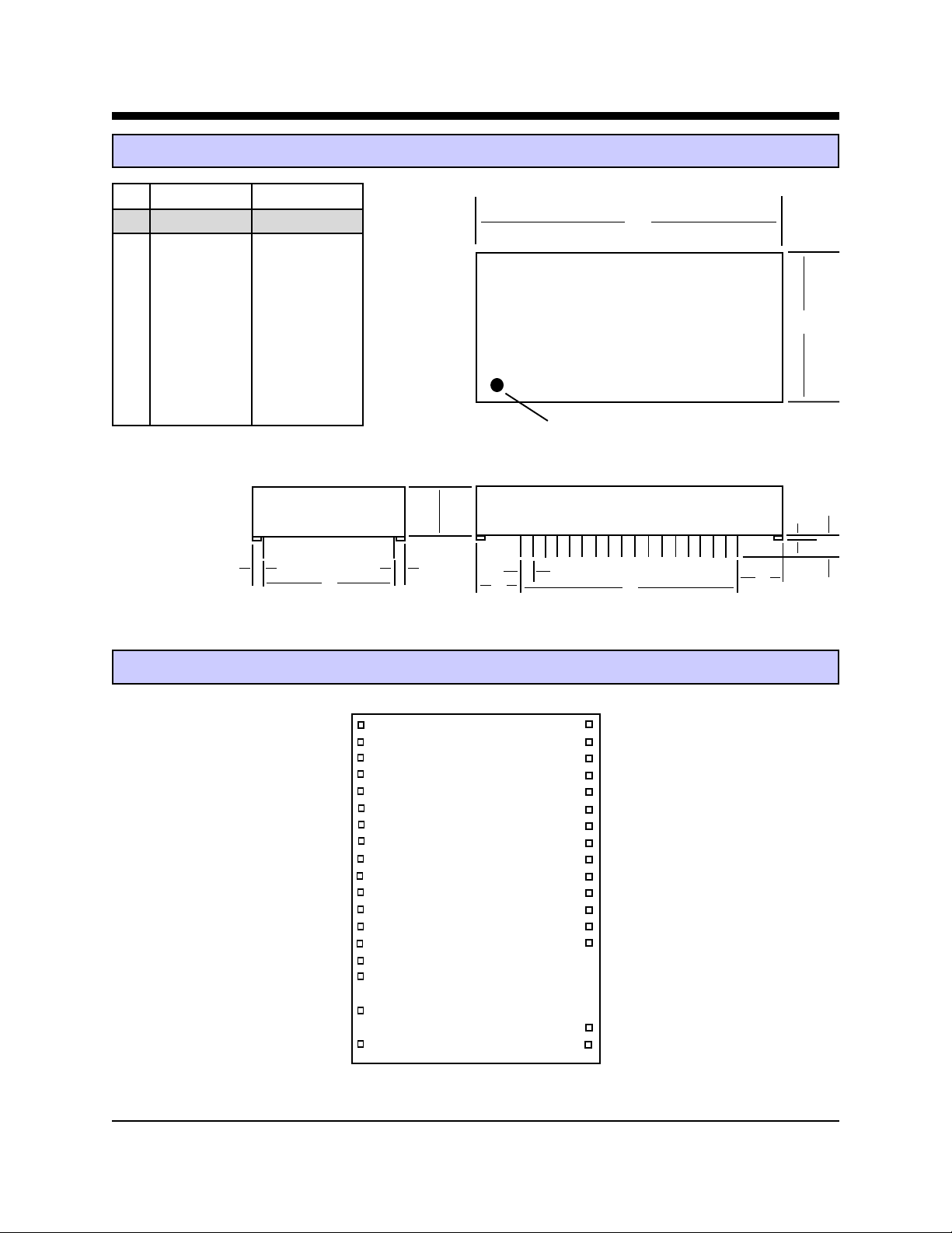
XE5614L Mechanical Specifications
INCHES METRIC(MM)
PIN MIN MAX MIN MAX
A 2.74 2.760 69.60 70.10
B 1.370 1.390 34.80 35.31
C 0.420 0.430 10.67 10.92
D 1.190 1.210 30.23 30.73
E 1.890 1.910 48.01 48.51
F 0.125 0.200 3.18 5.08
G 0.080 0.100 2.03 2.54
H 0.415 0.435 10.54 11.05
J 0.090 0.110 2.29 2.79
K 0.020 0.025 0.51 0.64
Pins = 0.025 inch square pin; All pins tin-plated
A
B
Denotes Pin 1
C
G
G
D
XE5614L PIN CONFIGURATION
NC
AR
RXD
NC
NC
NC
NC
NC
/DTR
NC
/CTS
NC
TXD
/RTS
NC
/RI
1
2
3
4
5
6
7
8
9
10
11
12
13
14
15
16
F
K
H
40
39
38
37
36
35
34
33
32
31
30
29
28
27
E
VCC
/DSR
/DCD
NC
RESET
NC
NC
NC
NC
NC
OH
NC
NC
NC
J
H
TIP
RING
18
20
22
21
AMP
GND
XECOM (2) XE5614L
Page 3

XE5614L PIN DESCRIPTIONS
PIN NAME DESCRIPTION
1 NC No Internal Connection
2 AR Auxiliary Data/Voice Relay, Active High Output, TTL/CMOS. The AR signal goes high when ever the
modem is in the on-hook state. It can be connected to an external relay to switch control of the telephone line between the modem and an auxiliary handset when.
3 RXD Received Data, Output, TTL. Serial data output to the host. A logic "High" on RXD represents a
"mark" and a logic "Low" represents a "space".
4-8 NC No Internal Connection
9 \DTR Data Terminal Ready, Input, active Low, TTL. The "AT&D" command sets the function of \DTR. The
default, AT&D2, requires the host to assert \DTR to permit a modem link. The modem drops the call in
progress if \DTR is revoked and will not connect until \DTR is reasserted.
10 NC No Internal Connection
11 \CTS Clear to Send, Output, active Low, TTL/CMOS. \CTS provides the flow control output from the modem
when hardware flow control is selected. The modem revokes \CTS when the modem's input buffer is
full. The modem reasserts \CTS when the buffer can accept more data without a buffer overflow.
12 NC No Internal Connection
13 TXD Transmit Data, Input, TTL. Serial data input from the host. A logic "High" represents a "mark" and a
Low represents a "space", TTL.
14 \RTS Request to Send, input, active Low, TTL. The XE5614L uses \RTS for hardware flow control. When
\RTS is revoked; hardware flow control is enabled, and the modem will not place data on RXD.
15 NC No Internal Connection
16 \RI Ring Indicator, Output, active Low, TTL. When low indicates the modem is receiving a ring signal.
18 TIP Tip connection to the phone line (RJ11 pin 3) from the internal DAA. The XE5614L is not sensitive to
the battery voltage polarity across Tip and Ring.
20 RING Ring connection to the phone line (RJ11 pin 4) from the internal DAA.
21 GND Ground (0 volts)
22 AMP Audio Output function is set by L & M commands and the value in register S22. This output can drive a
minimum load of 300 ohms.
27-29 N/C No Internal Connection
30 OH Off-Hook, Output, active High. OH indicates the modem's hookswitch relay is closed. Hookswitch clo-
sure connects the modem to the telephone line. This signal is available only on the XE5614L.
31-35 N/C No Internal Connection
36 RESET Hardware reset pin, Input, active High, TTL. A high on Pin 36 initiates a hardware reset. An external
reset is not required or recommended. The Reset pulse must be held a minimum of 100 milliseconds.
37 N/C No Internal Connection
38 \DCD Data Carrier Detect, Output Active Low, TTL/CMOS. The &C command sets the function of \DCD. In
the default state \DCD activates when a valid carrier is detected.
39 \DSR Data Set Ready, Output, active Low, TTL/CMOS. &S sets the \DSR function. In the default condition,
AT&S0, \DSR is forced true.
40 Vcc +5 Volts
XECOM (3) XE5614L
Page 4
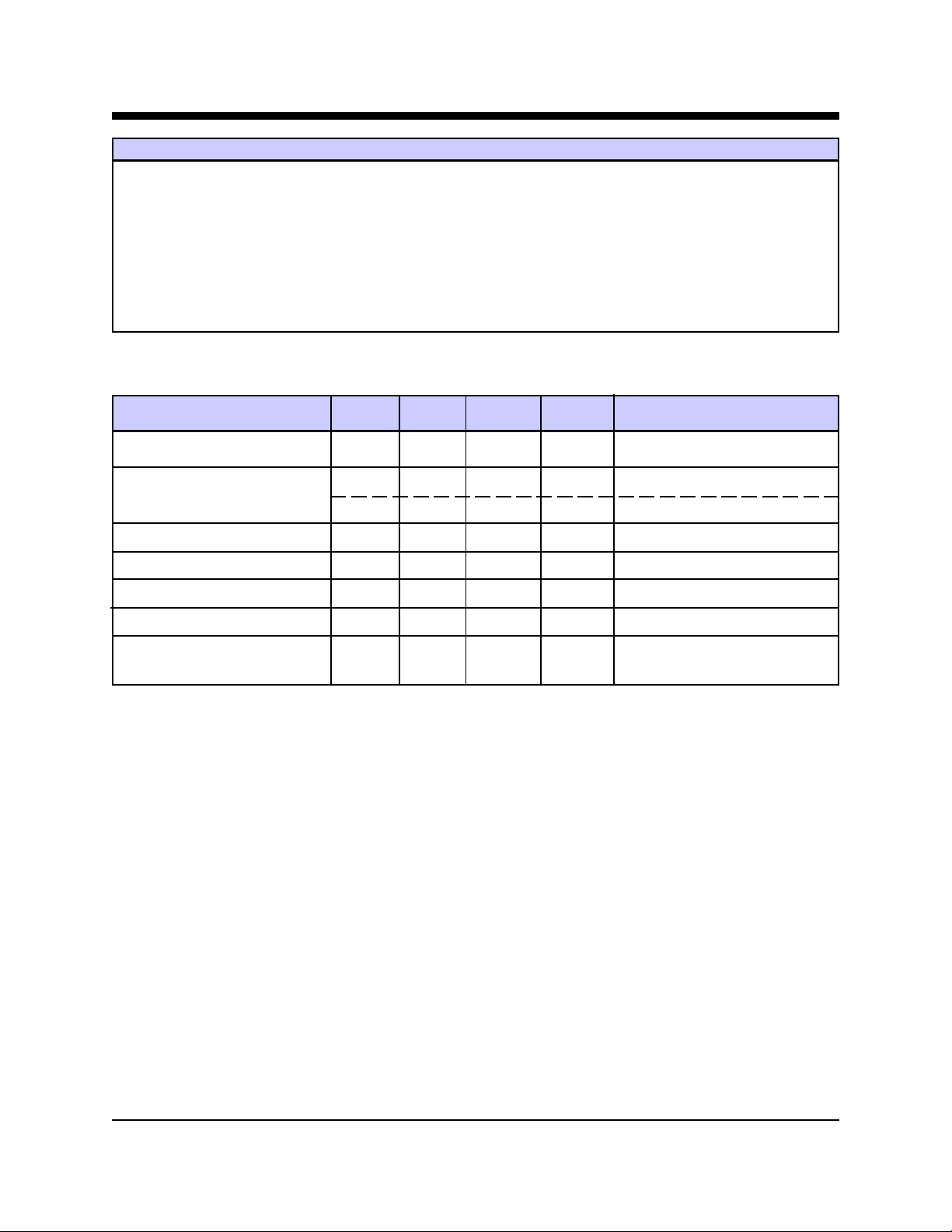
XE5614L ABSOLUTE MAXIMUM RATINGS
SUPPLY VOLTAGE - Vcc +6.5 Volts
DC INPUT VOLTAGE -0.6 Volts to +6.5 Volts
STORAGE TEMPERATURE RANGE -25° C TO +85° C
LEAD TEMPERATURE (Soldering, 2 sec per wave) 260° C
OPERATING TEMPERATURE RANGE 0 TO 70° C
*Exceeding these values may result in permanent damage to the device.
XE5614L ELECTRICAL SPECIFICATIONS
Parameter Min Typ Max Units Comments
VCC 4.75 5.25 Volts
ICC 130 150 170 ma On Line
45 Sleep Mode
Ring Voltage Detected 38 150 RMS Type B Ringer
Ring Frequency Detected 15.3 68 Hz T ype B Ringer
Telephone Loop Current 20 100 ma Off-Hook
Data Transmit level -12 -10.5 -9.0 dBm
DTMF Transmit Level -2.5 0 dBm Avg over 3 second interval
XECOM (4) XE5614L
Page 5
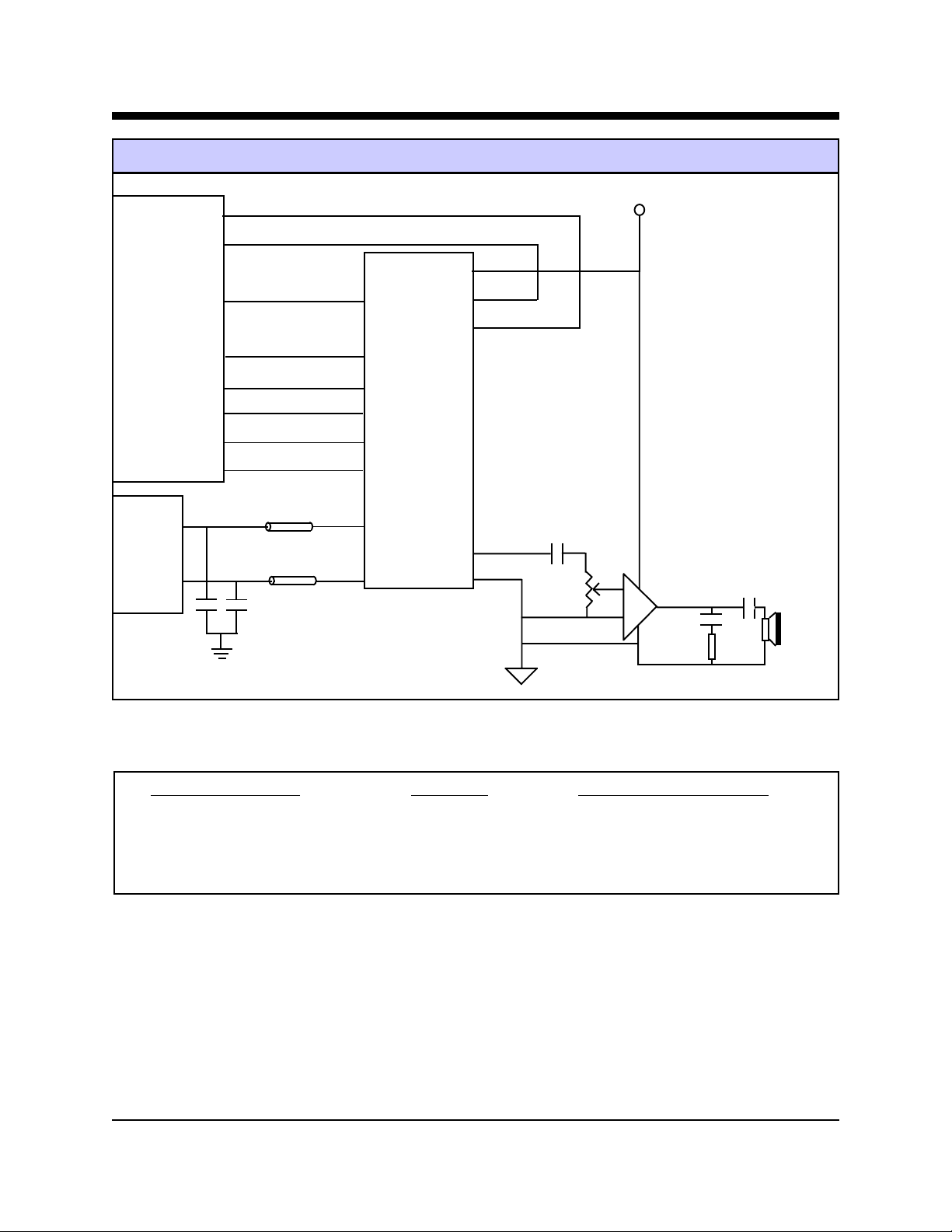
XE5614L Typical Connection Diagram
16C550
UART
RJ11
3
4
C1
/DCD
/DSR
SIN
/DTR
/CTS
SOUT
/RTS
/RI
C2
FB1
FB2
RXD
/DTR
/CTS
TXD
/RTS
/RI
TIP
RING
XE5614L
VCC
/DSR
/DCD
AMP
GND
.2 ufd
50K
+ 5 Volts
LM386
10 ohms
.05 ufd
250 ufd
8 ohm,
.5 W
speaker
Note: RJ11 Pin assignments reflect a 6-pin connector. Tip and Ring are always the center pins of the RJ11 Jack.
Recommended Parts
Reference Designation Description Recommended Part Number
FB1, FB2 Ferrite Beads TDK ACB2012L-120-X
C1, C2 Capacitors Panasonic ECKDRS471, 470 pfd, 2600 VAC
J1 RJ11 Jack Stewart SS6446NF
XECOM (5) XE5614L
Page 6

XE5614L AT COMMANDS
Modes of Operation
The XE5614L uses "AT" commands for modem control
and configuration. The XE5614L operates in three
modes; Command Mode, Fax Mode and Data Mode.
Extensions to the AT command set support fax
operation.
Data Mode: The modem enters data mode after
establishing a modem link and issues a "CONNECT"
result code. In Data Mode the modem modulates all
signals presented on Transmit Data, Pin 13, and sends
them to the remote modem. The modem demodulates
the signal from the remote modem and places it onto
Received Data, Pin 3, for the host equipment. When
the modem exits data mode, it issues a "NO CARRIER"
result code.
Command Mode: The XE5614L enters command
mode on application of power, reset, loss of the
connection, or receipt of the escape sequence. In
command mode the modem accepts commands from
the host on Transmit Data. Appropriate result codes are
returned on Received Data at the same speed and parity
as the commands.
Fax Mode: The modem enters fax mode on receipt of
the AT+FCLASS=1 command. Fax commands and
responses are issued at 19,200 bits per second; the
character format is 8 bits no parity . The modem accepts
Class 1 Fax commands only in fax mode. The A/, ATO,
AT&T and escape commands are not valid in fax mode.
Commands
The modem is configured and controlled with AT
commands. AT commands follow a strict format. The
command line is stored in the command buffer and
executed upon receipt of a carriage return. Until
executed, the command line can be edited with the
backspace key.
Command Line - A command line may include
multiple commands. The modem executes the
commands in the sequence they appear in the command
line. Spaces, inserted to improve legibility, do not fill
space in the command buffer. A carriage return
terminates the command line and causes the commands
to be executed. Register S3 allows the user to select a
character other than a carriage return to terminate the
command line.
Command Buffer - The command buffer holds a
maximum of 40 characters, including the AT prefix. If it
overflows, the modem issues an "ERROR" result code
and commands are not executed.
Command Line Editing - A backspace can be used to
edit the command line any time before it is executed.
The backspace character erases the previous character in
the command line. Any character except for the "A" and
"T" can be erased. Register S5 allows the user to select
a character other than a backspace to edit the command
line.
Re-Execute Last Command - The A/ command causes
the XE5614L to re-execute the command line stored in
the command buffer. This is the only command which
does not require the "AT" prefix.
Omitted Parameters - Most commands include a
parameter which determines the command function.
When the parameter is omitted from the command string,
it is assumed to be a 0.
Escape Characters - A three character escape sequence,
entered while in data mode, will switch the modem into
command mode while remaining on line. The escape
character, set by Register S2, is entered 3 times in
succession to execute the escape. The default escape
sequence is "+++."
Command Format - Each command, except A/, begins
with the AT prefix. The "A" and "T" may be both upper
case or both lower case but cannot be of different cases.
The modem uses the prefix to identify the host's speed
and parity. The modem determines speed by measuring
the width of the incoming bits and parity by comparing
the parity bits of the "A" and "T." The modem then
returns result codes at the host's speed and parity.
Result Codes - The modem issues a result code after
each action. Result codes may be provided as full words,
numeric codes or may be disabled. Each result code
ends with a carriage return when numeric result codes
are chosen. When full word result codes are chosen, a
Line Feed and Carriage Return precede and follow each
result code.
XECOM (6) XE5614L
Page 7

XE5614L AT COMMANDS (continued)
List of Commands
An asterisk indicates the default setting of the command for the
XE5614L.
A - Answer Command - ATA forces the modem to immediately go off-hook and begin transmitting the answer tone sequence.
Bn - Select Communications Standard - ATBn selects the
modulation scheme used for connections below 2400 bits per
second
n=0 Selects CCITT standards
n=1 Selects Bell standards*
D - Dial Command - Below are the characters accepted in a
dialing command.
0-9, #, * = Dialing Digits
L = Re-dial last number
P = Pulse dial
T = Tone dial
S=n = Dial stored number
W = Wait for dial tone
^ = Toggles state of calling tone
, = Pause for the duration of S8
@ = Wait for silence
! = Switch hook flash
; = Return to the command state
Mn - Speaker Activity - ATMn determines when the
modem's audio output is active.
n=0 Speaker off
n=1 Speaker on until carrier received*
n=2 Speaker remains on
n=3 Speaker off during dialing, on until carrier
On - On Line - ATOn switches the modem from the command
mode to the data mode.
n=0 Return On Line with no retrain*
n=1 Initiate retrain returning On Line.
Qn - Responses - ATQn determines if the modem will issue
responses.
n=0 Send responses*
n=1 No Responses
Sr? - Interrogate Register - ATSr? requests the current value
in register Sr.
Sr=n - Set Register Value - ATsr=n sets the value of register
Sr to n.
Vn - Result Codes - ATVn sets the modem to issue Numeric
or Full Word result codes .
n=0 Numeric Result Codes
n=1 English Word Result Codes*
En - Command Echo - ATEn determines whether commands
will be echoed back to the host.
n=0 Do not echo commands
n=1 Enable command echo*
Hn - Switch Hook Control - ATHn opens and closes the
modem's hook switch.
n=0 Switch hook relay opens
n=1 The switch hook relay closes
In - Modem Identification - ATIn identifies the modem version.
Ln - Speaker Volume - ATLn sets the amplitude of the
modem's audio output.
n=0 Lowest speaker volume
n=1 Low speaker volume*
n=2 Moderate speaker volume
n=3 High speaker volume
Wn - Connect Message Rate - ATWn determines whether
the data rate reported in the Connect response is the host data
rate, the link data rate or whether both are provide along with
the error control and data compression protocols negotiated.
n=0 Send "CONNECT" at DTE Rate*
n=1 Report line speed, DTE speed and Link protocol
n=2 "CONNECT" Reports Link speed
Xn - Result Code Set - ATXn selects which set of result
codes the modem may send.
n=0 Result codes 0 to 4
n=1 Result codes 0 to 5 and 10
n=2 Result codes 0 to 6 and 10
n=3 Result codes 0 to 5, 7 and 10
n=4 Full Result codes*
Zn - Reset - ATZn executes a soft reset to the modem and resets the modem configuration.
n=0 Reset to user profile 0*
n=1 reset to user profile 1
XECOM (7) XE5614L
Page 8

XE5614L AT COMMANDS (continued)
&Cn - DCD Operation - AT&Cn determines the operation of
the DCD output.
n=0 DCD is forced active.
n=1 DCD indicates a valid carrier*
&Dn - DTR - AT&Dn determines how the modem will respond to changes to DTR.
n=0 DTR is ignored by the modem.
n=1 Enter command mode if DTR revoked.
n=2 Disconnect if DTR revoked.*
n=3 Soft reset when DTR revoked
&Fn - Return to Factory Defaults - AT&Fn returns the modem configuration to one of two factory configurations.
n=0 Restore configuration 0*
n=1 Restore configuration 1
&Gn - Guard Tone - AT&Gn controls the guard tone produced by the modem
n=0 Guard Tone Disabled*
n=1 Guard Tone Disabled
n=2 1800 Hz Guard Tone
&Kn - Flow Control - AT&Kn selects the flow control
method used by the modem.
n=0 Disabled
n=3 RTS/CTS
n=4 XON/XOFF
n=5 Transparent XON/XOFF
&Pn - Dial Pulse Make/Break Ratio - AT&Pn determines
the specific pulse dialing parameters used by the modem.
n=0 39/61% @ 10 pps*
n=1 33/67% @ 10 pps
n=2 39/61% @ 20 pps
n=3 33/67% @ 20 pps
&Qn - Line Connection - AT&Qn determines if error control
or data buffering are active on the link.
n=0 Direct mode (no data buffering)*
n=5 Use Error Correction
n=6 Normal Mode (Speed buffering)
&Sn - DSR Operation - AT&Sn sets the operation of the
DSR signal.
n=0 DSR always active*
n=1 DSR in accordance with V.25.
&Tn - Test Modes - AT&T selects modem test modes.
n=0 Exit test mode
n=1 Local analog loopback
&Vn - View Configuration Profiles - AT&V permits the user
to check on the modems current configuration or conditions of
the last call
n=0 View active profile & user profile 0*
n=1 View statistics on last call
&Wn - Store Active Profile - AT&Wn stores the current modem configuration in NVRAM.
n=0 Store active profile as profile 0*
n=1 Store active profile as profile 1
&Yn - Recall Stored Profile - AT&Yn sets the stored modem
configuration to be used after a hard reset.
n=0 Recall profile 0 on power-up*
n=1 Recall profile 1 on power-up
&Zn=x - Store telephone number "x" in memory location
"n"
%En - Line Quality Monitor/Auto Retrain - AT%En deter-
mines if the modem will monitor line quality during a connection and initiate a retrain if quality drops below acceptable levels.
n=0 Disabled
n=1 Enabled
n=2 Line quality, fallback, fall forward
%L - Read Received Signal Level - AT%L
to read the magnitude of the receive signal in dBm.
%Q - Read Line Signal Quality - AT%Q permits the user to
read the EQM value of the received signal.
\\Bn - Transmit Break - AT\Bn selects the duration of the
break signal sent. Break = n x 100 msec.
\Gn - Modem Port Flow Control -
n=0 No Modem Port Flow Control
n=1 XON/XOFF Port Flow Control
permits
the user
XECOM (8) XE5614L
Page 9

XE5614L AT COMMANDS (continued)
\Kn - Break control - AT\Kn determines how the modem will
handle a break signal received from the host.
Break received from host in data transfer mode.
n=0 Enter on-line command mode; do not transmit
break
n=1 Purge buffers, immediately transmit break
n=2 Same as n=0
n=3 Immediately send break
n=4 Same as n=0
n=5 Send break in sequence with data *
Break received from the host during the on-line
command mode.
n=0 Purge buffers, immediately transmit break
n=1 Same as n=0
n=2 Immediately send break
n=3 Same as n=2
n=4 Send break in sequence with data
n=5 same as n=4 *
Break received from modem during a non-error corrected link
n=0 Purge buffers, Immediately send break to host
n=1 same as n=0
n=2 Immediately send break to the host
n=3 Same as n=2
n=4 Send break in sequence with data.
n=5 Same as n=2*
\Nn - Error Control Selection - AT\Nn determines how the
modem will handle error control negotiations.
n=0 Normal mode, no error correction
n=1 Direct mode, no buffering, no error correction
n=2 Reliable mode, error correction required
n=3 V.42 Auto-reliable mode, accept either an error
controlled or non-error controlled link*
n=4 V.42 Reliable mode, LAPM required
n=5 MNP required
-Kn - MNP Extended Services - AT-Kn determines how the
modem handles MNP10.
n=0 No LAPM to MNP10 conversion
n=1 LAPM to MNP10 conversion*
n=2 LAPM to MNP10 conversion but no MNP Extended Service during V.42 LAPM answer mode detect.
+MS - Select Modulation - AT+MS sets the modulation and
data rates to be supported by the modem. The format for
the +MS command is shown below.
AT+MS=a, b, c, d, e, f<CR>
a - modulation type
B103 - Bell 103 (300 BPS)
B212 - Bell 212A (1200 BPS)
V21 - V.21 (300 BPS)
V22 - V.22 (1200 BPS)
V.22B - V.22bis (1200 or 2400 BPS)
V23 - V.23 (1200 Tx / 75 RX or 75 Tx / 1200 Rx)
V32 - V.32 (4800 or 9600 BPS)
V32B - V.32bis (4800 to 14,400 BPS)
V90 - V.90 (to 56,000 BPS)
K56 - K56Flex (to 55,667 BPS)
b - Automode Detection
0 - Automatic Negotiation Disabled
1 - Automatic Negotiation Enabled
c - Minimum Receive Data Rate (300 to 56000 BPS)
d - Maximum Receive Data Rate (300 to 56000 BPS)
e - Minimum Transmit Data Rate (300 to 56000 BPS)
f - Maximum Transmit Data Rate (300 to 56000 BPS)
Default: AT+MS=V90, 1, 300, 300, 300, 56000
/V<value> - Single Line Connect Messages - This command
allows users to select single line connect messages in the
format shown below.
<DTE Speed> <Modulation> <Protocol> <Compression>
<Line Speed> <Voice & Data>
n=0 No single Line Connect Messages
0 - Automatic Negotiation Disabled
1 - Automatic Negotiation Enabled
XECOM (9) XE5614L
Page 10

XE5614L Modem Registers
S0 Answer on nth Ring: S0 sets the modem to
automatically answer on the nth ring. Setting S0 to 0
disables automatic answer.
Range: 0 to 255
Units Rings
Default 0
S1 Ring Count: S1 is a read-only register showing the
number of rings detected. If a ring is not detected within
8 seconds, S1 is reset to zero.
Range: 0 to 255
Units Rings
Default 0
S2 Escape Character: S2 sets the ASCII escape character.
Values of 0-127 select valid ASCII escape characters;
values from 128 to 255 disable the escape sequence.
Range: 0 to 255
Units ASCII Character
Default 43 (+)
S3 Carriage Return Character: S3 determines the ASCII
character to serve as a carriage return to terminate
commands and modem responses.
Range: 0 to 127
Units ASCII Character
Default 13 (Carriage Return)
S4 Line Feed Character: S4 sets the ASCII character to
act as a line feed character in modem responses.
Range: 0 to 127
Units ASCII Character
Default 10 (Line Feed)
S5 Back Space Character: S5 defines the ASCII character
used as a backspace to edit the command line.
Range: 0 to 32
Units ASCII Character
Default 8 (Back Space)
S6 Dial Tone Wait Time: S6 determines how long the
modem waits for dial tone before dialing begins. The
Dial Tone Wait Time cannot be set to less than two
seconds.
Range: 2 to 255
Units Seconds
Default 2
S7 Wait for Carrier after Dialing: S7 determines how long
the modem waits for a valid carrier signal after dialing.
Range: 1 to 255
Units Seconds
Default 50
S8 Comma Pause Time: S8 defines the duration of the
pause set by a comma in the dialing string. The pause is
generally used when waiting for a second dial tone.
Range: 1 to 255
Units Seconds
Default 50
S9 Reserved
S10 Carrier Off Disconnect Delay: S10 selects how long
carrier must be lost before the modem disconnects.
Range: 1 to 255
Units 0.1 Seconds
Default 14
S11 Tone Dialing Speed: S10 sets the duration and spacing of
the dialing tones. S11 does not affect pulse dialing.
Range: 50 to 255
Units 1 Millisecond
Default 95
S12 Escape Code Guard Timer: S12 sets the guard timer for
the escape sequence. If characters are received within the
guard time, the modem aborts the escape attempt and
remains in data mode.
Range: 0 to 255
Units 0.02 Seconds
Default 50
S14 General Bit-Mapped Options: S14 reflects the state of
several "AT" commands.
Bit 0,4,6 Not Used
Bit 1 0 = Echo Disabled (ATE0)
1 = Echo Active (ATE1)
Bit 2 0 = Send Result Codes (ATQ0)
1 = No Result Codes (ATQ1)
Bit 3 0 = Numeric Result Codes (ATV0)
1 = Full Word Result Codes (ATV1)
Bit 5 0 = Tone Dialing Selected (T)
1 = Pulse Dialing Selected (P)
Bit 7 0 = Answer
1 = Originate
XECOM (10) XE5614L
Page 11

XE5614L Modem Registers (continued)
S16 Test Status: S16 shows the modem test status.
Bit 0 0 = No Local Analog Loopback
1 = Local ALB Active
Bit 1-7 Not Used
S21 General Bit-Mapped Options: S21 reflects the state
of several "AT" commands.
Bit 0-2, 7 Not Used
Bit 3,4 0 = DTR ignored (&D0)
1 =
Enter command mode on DTR off
2 = Disconnect on DTR off (&D2)
3 = Reset on DTR off (&D3)
Bit 5 0 = DCD always active (&C0)
1 = DCD on with Carrier (&C1)
Bit 6 0 = DSR always active (&C0)
1= DSR on when modem ready (&C1)
S22 General Bit-Mapped Options: S22 reflects the state
of several "AT" commands.
Bit 0-1 0 = Low speaker volume (ATL0)
1 = Low speaker volume (ATL1)
2
= Moderate speaker volume (ATL2)
3 = High speaker volume (ATL3)
Bit 2-3 0 = Speaker off (ATM0)
1 = Speaker off with carrier (ATM1)
2 = Speaker always on (ATM2)
3 = Speaker on during handshake (ATM3)
Bit 4-6 0 = Basic Result codes (ATX0)
4
= Connect speed result codes (ATX1)
5 = No Blind Dial (ATX2)
6 = Busy Detection (ATX3)
7 = Full result codes (ATX4)
Bit 7 Not Used
S23 General Bit-Mapped Options: S23 reflects the state
of several "AT" commands.
Bit 0-5 Not Used
Bit 6-7 0 = No Guard Tone (AT&G0)
1 = No Guard Tone (AT&G1)
2 = 1800 Hz guard tone (AT&G2)
3 = Not Used
S24 Sleep Mode Timer: S24 sets the length of time in
seconds that the modem must be idle before entering the
low power, sleep mode. When S24 is set to 0, sleep
mode is disabled.
Range: 0 to 255
Units: seconds
Default: 0
(&D1)
S27 General Bit-Mapped Options: S27 reflects the state
of several "AT" commands.
Bit 0 1 3
0 0 0 = Normal Mode (AT&Q0)
101
011
Bit 2, 4-5, 7 Not Used
Bit 6 0 = CCITT Protocols (ATB0)
S28 Pulse Dialing Bit-Mapped Options: S28 stores the
modem's pulse dialing configuration.
Bit 0-2, 5-7 Not Used
Bit 3-4 0 = Make/Break ratio 39%/61%; 10
S29 Hook Flash Timer: S29 determines the length for
time the modem closes its off-hook relay on receipt of
the "!" dial modifier to simulate a switch hook flash.
Range: 0 to 255
Units 10 milliseconds
Default 70
S30 Disconnect on Inactivity Timer: S30 sets the
periond the modem is idle before it disconnects. A 0
disables the inactivity timer.
Range: 0 to 255
Units 10 Seconds
Default 0
S31 General Bit-Mapped Options: S31 stores the status
of various AT commands.
Bit 0 0 =
Bit 1 0 = No Automode detection (ATN0)
Bit 2-3 0 = Report host speed (ATW0)
Bit 4-7 Not Used
= Error control enabled (AT&Q5)
= Direct Mode (AT&Q6)
1 = Bell Protocols (ATB1)
pulses per second (AT&P0)
1 = Make/Break ratio 33%/67%; 10
pulses per second (AT&P1)
2 = Make/Break ratio 39%/61%; 20
pulses per second (AT&P2)
3 = Make/Break ratio 33%/67%; 20
pulses per second (AT&P3)
No single-line Connect messages
1 =
Use single-line connect messages
1 =
Automode detection active (A TN1)
1 = Report all parameters (ATW1)
2 =
Report modem speed only (ATW2)
(AT\V0)
(AT\V1)
XECOM (11) XE5614L
Page 12

XE5614L Modem Registers (continued)
S36 LAPM Failure: S36 instructs the modem what to do
if the error control negotiations fail.
Bit 0-2 0 = Modem Disconnects
1 = Establish Direct Connection
3 = Establish normal Connection
4 = Disconnect if MNP handshake fails
5 = Establish Direct Connection if
MNP handshake fails.
7 = Establish Normal Connection if
MNP handshake fails.
Bit 3-7 Not Used
S38 Forced Disconnect Timer: S38 sets the delay be-
tween receipt of the command to disconnect and the
actual opening of the switch hook. If S38 is set to 255
the modem disconnects only after its buffers are empty.
Range: 0 to 255
Units 1 Second
Default 20
S39 Flow Control Bit-Mapped Options: S39 shows the
modem's flow control status, AT&K.
Bit 0-2 0 = Flow Control Disabled
3 =
Hardware Flow Control, RTS/CTS
4 =
In-Band Flow Control XON/XOFF
5 =
Transparent In-Band Flow Control
Bit 3-7 Not use
S40 MNP Bit-Mapped Options: S40 shows the status of
the modem's MNP commands, .
Bit 0-1 0 = No LAPM/MNP10 conversion (AT-K0)
1 = Enable LAPM/MNP10 conversion
(AT-K1)
2 = Enable LAPM to MNP10 conversion ex
cept for LAPM answer mode (AT-K1)
Bit 2 Not Used
Bit 3-5 0 = AT\K0 break handling selected
1 = AT\K1 break handling selected
2 = AT\K2 break handling selected
3 = AT\K3 break handling selected
4 = AT\K4 break handling selected
5 = AT\K5 break handling selected
Bit 6-7 Not Used
S41 General Bit-Mapped Options: S41 stores the condi-
tion of various "AT" commands.
Bit 0-1 0 = No Data Compression (AT%C0)
1 = MNP5 Data Compression (AT&C1)
2 = V.42bis Data Compression (AT&C2)
3 = Either MNP5 or V.42bis (AT&C3)
Bit 2, 6
0 0 = No Fallback/Forward (AT%E0)
1 0 = Retrain Enabled (AT%E1)
0 0 = Fallback/Forward Enabled (AT%E2)
Bit 3-5, 7 Not Used
S46 Data Compression Control: S46 selects whether or
not the modem will support data compression.
S46=136 No data compression
S46=138 Data Compression selected
Default 1 38
S48 V.42 Negotiations: S48 determines the modem's V.42
negotiation process.
S48=0 Proceed with LAPM
S48=7 Negotiate per V.42*
S48=128 Assume LAPM failure
S86 Call Failure Code: S86 shows why the last "NO CAR-
RIER response was issued.
S86=0 Normal Disconnect
S86=3 Call Waiting caused Disconnect
S86=4 Loss of Carrier
S86=5 V.42 Negotiation Failure
S86=6 No response to feature Negotiation
S86=7 Other modem is Synchronous modem
S86=8 No common framing technique
S86=9 Modem Handshake Failure
S86=10 Bad response to Feature Negotiation
S86=12 Disconnect Initiated by remote modem
S86=13 No response after 10 retries
S86=14 Protocol Violation
S86=15 Lost DTR
S86=16 Received GSTN cleardown
S86=17 Inactivity timeout
S86=18 Speed not supported
S86=20 Key abort disconnect
S86=22 No connection established
S86=23 Disconnect after 3 retrains
S86=24 Call Waiting tone detected
XECOM (12) XE5614L
Page 13

XE3314L Modem Registers (continued)
S95 Extended Result Codes: S95 permits the user to customize the extended result
Bit 0 Connect result code shows link speed
Bit 1 Add /ARQ to connect response
Bit 2 Add /VFC to Carrier response
Bit 3 Enable Protocol response
Bit 4 Not Used
Bit 5 Enable Compression Result Code
Bit 6 Not used
Bit 7 Not Used
XE5614L Class 1 Fax Commands
AT+FCLASS? - Service Class Indication
0 = Configured as a data modem
1 = Configured for Service Class 1.
AT+FCLASS=? - Service Class Capability
0 = Configured as a data modem
1 = Configured for Service Class 1.
AT+FCLASS=n - Set Service Class
0 = Configured as a data modem
1 = Configured for Service Class 1.
AT+FAE=n - Data/Fax Auto Answer
0 = Answer as a fax modem only
1 = Either a fax or data modem
AT+FF - Enhanced Flow Control
AT+FRH<mod> - Receive HDLC Data
3 V.21 Channel 2, 300 bps
24 V.27ter, 2400 bps
48 V.27ter, 4800 bps
72 V.29, 7200 bps
96 V.29, 9600 bps
97 V.17, 9600 bps
98 V.17 short train, 9600 bps
121 V.17, 12,000 bps
122 V.17 short train, 12,000 bps
145 V.17, 14,400 bps
146 V.17 short train, 14,400 bps
AT+FRM<mod> - Receive Fax
(see AT+FRH for "mod" values)
AT+FRS<time> - Receive Silence
AT+FRTn - Receive Test Data
AT+FTH<mod> - Transmit HDLC Data
(see AT+FRH for "mod" values)
AT+FTM<mod> - Transmit Fax
(see AT+FRH for "mod" values)
A T+FTS<time> - Transmit Silence
AT+FTTn - Transmit Test Data
codes.
XECOM (13) XE5614L
Page 14

XE5614L Modem Result Codes
Digits Verbose Description
0 OK Successfully executed command line
1 CONNECT 300 bps connection
2 RING Ring signal detected
3 NO CARRIER Carrier not detected/lost
4 ERROR Error in command line
5 CONNECT 1200 1200 bps connection
6 NO DIAL TONE No dial tone detected
7 BUSY Busy signal detected
8 NO ANSWER 5 second silence not detected
9 CONNECT 600 600 bps connection
10 CONNECT 2400 2400 bps Connection
11 CONNECT 4800 4800 bps Connection
12 CONNECT 9600 9600 bps Connection
13 CONNECT 7200 7200 bps Connection
14 CONNECT 12000 12,000 bps Connection
15 CONNECT 14400 14,400 bps Connection
16 CONNECT 19200 19,200 bps Connection
17 CONNECT 38400 38,400 bps Connection
18 CONNECT 57600 57,600 bps Connection
19 CONNECT 115200 115200 bps Connection
22 CONNECT 75TX/1200RX .23 originate connection
23 CONNECT 1200TX/75RX V.23 answer connection
33 F A X Fax connection
35 DATA Data connection in Fax mode
40 +MRR: 300 300 bps carrier received
44 +MRR: 1200/75 V.23 reverse channel carrier received
45 +MRR: 75/1200 V.23 forward channel carrier received
46 +MRR: 1200 1200 bps carrier received
47 +MRR: 2400 2400 bps carrier received
48 +MRR: 4800 4800 bps carrier received
49 +MRR: 7200 7200 bps carrier received
50 +MRR: 9600 9600 bps carrier received
51 +MRR: 12000 12,000 bps carrier received
52 +MRR: 14400 14,400 bps carrier received
53 +MRR: 16800 16,800 bps carrier received
54 +MRR: 19200 19,200 bps carrier received
55 +MRR: 21600 21,600 bps carrier received
56 +MRR: 24000 24,000 bps carrier received
57 +MRR: 26400 26,400 bps carrier received
58 +MRR: 28800 28,800 bps carrier received
59 CONNECT 16800 16,800 bps connection
61 CONNECT 21600 21,600 bps connection
62 CONNECT 24000 24,000 bps connection
63 CONNECT 26400 26,400 bps connection
64 CONNECT 28800 28,800 bps connection
66 +DR: Alt MNP5 data compression
67 +DR: V42B V.42bis data compression
69 +DR: NONE No data compression
Digits Verbose Description
70 +ER: NONE No error correction
77 +ER: LAPM LAPM error correction
78 +MRR:31200 31,200 bps carrier received
79 +MRR: 33600 33,600 bps carrier received
80 +ER: ALT MNP error correction
81 +ER: ALT CELLULAR MNP10 error correction
84 CONNECT 33600 33,600 bps Connection
91 CONNECT 31200 31,200 bps Connection
134 +MCR: B103 Bell 103 Connection
135 +MCR: B212 Bell 212A Connection
136 +MCR: V21 V.21 Connection
137 +MCR: V22 V.22 Connection
138 +MCR: V22B V.22bis Connection
139 +MCR: V23 V.23 Connection
140 +MCR: V32 V.32 Connection
141 +MCR: V32B V.32bis Connection
142 +MCR: V34 V.34 Connection
144 +MCR: K56 K56 Flex Connection
145 +MCR: V90 V.90 Connection
150 +MRR: 32000 32,000 BPS Carrier Received
151 +MRR: 34000 34,000 BPS Carrier Received
152 +MRR: 36000 36,000 BPS Carrier Received
153 +MRR: 38000 38,000 BPS Carrier Received
154 +MRR: 40000 40,000 BPS Carrier Received
155 +MRR: 42000 42,000 BPS Carrier Received
156 +MRR: 44000 44,000 BPS Carrier Received
157 +MRR: 46000 46,000 BPS Carrier Received
158 +MRR: 48000 48,000 BPS Carrier Received
159 +MRR: 50000 50,000 BPS Carrier Received
160 +MRR: 52000 52,000 BPS Carrier Received
161 +MRR: 54000 54,000 BPS Carrier Received
162 +MRR: 56000 56,000 BPS Carrier Received
165 CONNECT 32000 32,000 bps connection
166 CONNECT 34000 34,000 bps connection
167 CONNECT 36000 36,000 bps connection
168 CONNECT 38000 38,000 bps connection
169 CONNECT 40000 40,000 bps connection
170 CONNECT 42000 42,000 bps connection
171 CONNECT 44000 44,000 bps connection
172 CONNECT 46000 46,000 bps connection
173 CONNECT 48000 48,000 bps connection
174 CONNECT 50000 50,000 bps connection
175 CONNECT 52000 52,000 bps connection
176 CONNECT 54000 54,000 bps connection
177 CONNECT 56000 56,000 bps connection
178 CONNECT 230400 230,400 bps connection
180 CONNECT 28000 28,000 bps connection
181 CONNECT 29333 29,333 bps connection
XECOM (14) XE5614L
Page 15

XE5614L Modem Result Codes (continued)
Digits Verbose Description
182 CONNECT 30667 30,667 bps connection
183 CONNECT 33333 33,333 bps connection
184 CONNECT 34667 34,667 bps connection
185 CONNECT 37333 37,333 bps connection
186 CONNECT 38667 38,667 bps connection
187 CONNECT 41333 41,333 bps connection
188 CONNECT 42667 42,667 bps connection
189 CONNECT 45333 45,333 bps connection
190 CONNECT 46667 46,667 bps connection
191 CONNECT 49333 49,333 bps connection
192 CONNECT 50667 50,667 bps connection
193 CONNECT 53333 53,333 bps connection
194 CONNECT 54667 54,667 bps connection
195 +MRR: 28000 28,000 BPS Carrier Received
196 +MRR: 29333 29,333 BPS Carrier Received
Digits Verbose Description
197 +MRR: 30667 30,667 BPS Carrier Received
198 +MRR: 33333 33,333 BPS Carrier Received
199 +MRR: 34667 34,667 BPS Carrier Received
200 +MRR: 37333 37,333 BPS Carrier Received
201 +MRR: 38667 38,667 BPS Carrier Received
202 +MRR: 41333 41,333 BPS Carrier Received
203 +MRR: 42667 42,667 BPS Carrier Received
204 +MRR: 45333 45,333 BPS Carrier Received
205 +MRR: 46667 46,667 BPS Carrier Received
206 +MRR: 49333 49,333 BPS Carrier Received
207 +MRR: 50667 50,667 BPS Carrier Received
208 +MRR: 53333 53,333 BPS Carrier Received
209 +MRR: 54667 54667 BPS Carrier Received
+F4 +FCERROR Fax carrier error
XECOM (15) XE5614L
Page 16

XE5614L FCC Registration
All equipment connected to the public telephone network in
the United States must have FCC Part 68 Registration. Part 68
registration certifies that the device will not cause harm to the
telephone network. The XE5614L provides a user transferable
FCC Registration. This permits XE5614L customers to use
our FCC registration number without submitting their systems
for additional testing. Call Xecom technical support at 408945-6640 with any questions on whether your system qualifies
to use Xecom's FCC Registration Number.
In your operating instructions you must provide certain information to the end user of the modem. The instructions should
include most of the instructions shown below. Only the
information regarding the mounting of the device in the final
assembly should be omitted.
FCC Instructions:
his product complies with Part 68 of the FCC Rules and
T
Regulations. On each device shipped, there is a label which
contains, among other information, the FCC Registration
Number and Ringer Equivalence Number (REN) for this
product. You must, upon request, provide this information to
your telephone company.
The mounting of this device in the final assembly must be
made in such a manner as to preserve the high voltage
protection between the TIP/RING Connection and the rest of
the system. Typically, this may be accomplished by maintaining a minimum spacing .100 mils between the TIP/RING
Traces to the RJ-11C Jack and low voltage portion of the
system. No additional circuitry may be attached between TIP/
RING and the telephone line connection, unless specifically
allowed in the rules.
If your system causes harm to the telephone network, the
telephone company may discontinue service temporarily. If
possible, they will notify you in advance. If advance notification is not practical, you will be notified as soon as possible.
Your telephone company may make changes in its facilities,
equipment, operations or procedures that could affect proper
functioning of your equipment. If they do, you will be notified
in advance to give you an opportunity to maintain uninterrupted telephone service.
If you experience trouble with this device, please contact
XECOM at (408) 945-6640 for assistance. The telephone
company may ask you to disconnect this device from the
network until the problem has been corrected or until you are
sure that the device is not malfunctioning.
The device may not be used on coin service lines provided by
the telephone company (this does not apply to private coin
telephone applications which use standard telephone lines).
Connection to party lines is subject to state tariffs.
FCC Labels:
FCC rules also require a label which is visible from the outside
of the equipment. The label should display Xecom's name as
holder of the FCC Registration, the FCC Registration Number
and Ringer Equivalence of the modem. This is the same
information which appears on the top of each XE5614L
module.
The REN is useful to determine the quantity of devices you
may connect to a telephone line and still have all of these
devices ring when the number is called. In most, but not all
areas, the sum of the RENs of all devices connected to one line
should not exceed five (5.0). To be certain of the number of
devices you may connect to the line, as determined by the
REN, you should contact the local telephone company to
determine the maximum REN for your calling area.
XECOM (16) XE5614L
Page 17
Terms of Sale
Devices sold by XECOM are covered by the warranty provisions appearing in its Terms of Sale only. XECOM makes no warranty, express, statutory, implied, or by description regarding the information set forth herein, or regarding the freedom of the
described devices from patent infringement. XECOM makes no warranty of merchantability or fitness for any purposes.
XECOM reserves the right to discontinue production and change specifications and prices at any time and without notice.
This product is intended for use in normal commercial applications. Applications requiring extended temperature range, unusual environmental requirements, or high reliability applications, such as military, medical life-support or life-sustaining
equipment, are specifically not recommended without additional processing and authorization by XECOM for such application.
Xecom assumes no responsibility for the use of any circuitry other than circuitry embodied in a Xecom product. No other circuits, patents, or licenses are implied.
Life Support Policy
Xecom's products are not authorized for use as Critical Components in Life Support Devices or Systems.
Life Support Devices or Systems are devices or systems which, (a) are intended for surgical implant into the body, or (b) support or sustain life, and whose failure to perform, when properly used in accordance with instructions provided in the labeling,
can be reasonably expected to result in significant injury to the user.
A Critical Component is any component of a life support device or system whose failure to perform can be reasonably expected to cause failure of the life support device or system, or to affect its safety or effectiveness.
Copyright, Xecom © 2000
While Xecom, Inc. has made every effort to ensure that the information presented here is accurate, Xecom will not be liable for
any damages arising from errors or omission of fact. Xecom reserves the right to modify specifications and/or prices without
notice. Product mentioned herein are used for identification purposes only and may be trademarks and/or registered trademarks
of their respective companies.
Xecom Inco rporate d
374 Turquoise Street, Milpitas, CA 95035
Ph:408-945 -6640 Fax:408 -942-1346
XECOM (17) XE5614L
 Loading...