

Page 1
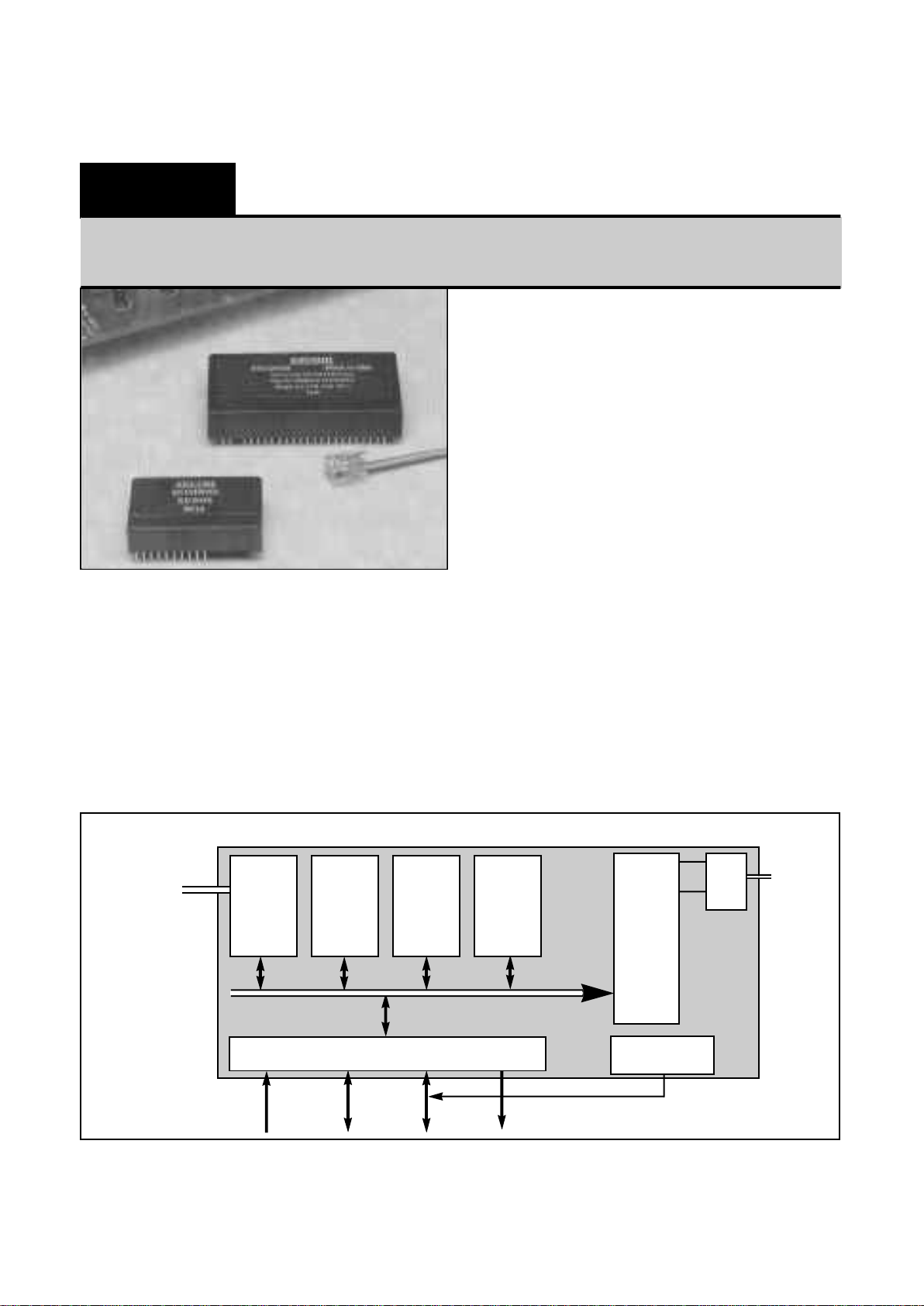
Description:
The Blackjack Tele-Controller is a rugged, miniature
controller with an integrated modem. Xecom based the
Tele-Controller on an 80C552 micro-controller. It provides
32 Kbytes each of ROM and RAM, 128 Kbytes of Flash
memory, 26 I/O lines and the modem. The XE5224DM
includes a 2400 bit per second data modem; The XE5224FD
adds send and receive fax . Firmware embedded in the
Tele-Controller provides development tools which allow
manipulation of both program and data memory.
Features:
* Small size: 2.75" x 1.38" x 0.50"
* Philips 80C552 micro-controller, at 14.7456 MHz;
* 26 I/O lines Includes:
Two 8-bit Digital I/O Ports;
Eight I/O lines available as inputs to 10 bit A/D;
Two PWM outputs;
* I/O Compatible with Opto 22/Grayhill series modules;
* 32 Kbyte Pre-programmed internal ROM ;
* 32 Kbyte SRAM for data storage;
* 128 Kbyte Flash memory for program and data storage;
* Real Time Calendar/Clock (External battery backup)
* 2400 bps data modem, XE5224DM or 2400 bps modem
with send & receive fax , XE5224FD;
* Typical Power:
Controller active, Modem idle: +5 Volts @ 55 milliamps;
Controller and Modem active: +5 Volts @ 95 milliamps;
* Serial Port for RS232 or RS485 communications;
* Development Kit available;
* Sturdy, encapsulated construction seals circuits from
harsh environments;
* Industrial Temperature Range available;
XE5224DM & XE5224FD
10-03-95
xecom
Blackjack Tele-Controller
80C552 based controller with 2400 bps data modem (send/receive fax optional)
Tele-Controller Block Diagram
Modem
DAA
To
Telephone
Line
80C552
Micro-
controller
32 KByte
SRAM
32 Kbyte
ROM
128 Kbyte
Flash-
Memory
8 Analog/Digital 8 Digital 8 Digital 2 Channels
Input Channels I/O Channels I/O Channels PWM Output
Real-Time
Calendar/Clock
To RS232
or RS485
Page 2
1 TIP One of the signals forming the two-
wire connection to the telephone line.
The Tele-Controller is not sensitive to
the polarity of the battery voltage on
the telephone line.
2 RING The second wire of the two-wire
connection to the telephone line.
3 N/P No Pin
4 OH Off Hook is an active high output from
the Tele-Controller. A high indicates
the internal modem has seized the
telephone line.
5 SPKR SPKR is the audio output from the
Tele-Controller. It permits the user to
monitor the activity on the telephone
line by connecting a speaker. The
load on SPKR must be at least 300
ohms.
6 /SLEEP SLEEP is an active low output from
the Tele-Controller. A low indicates
the modem within the Tele-Controller
is operating on reduced power in the
"sleep" mode.
7 N/C No connection
XECOM (2) XE5224DM & XE5224FD
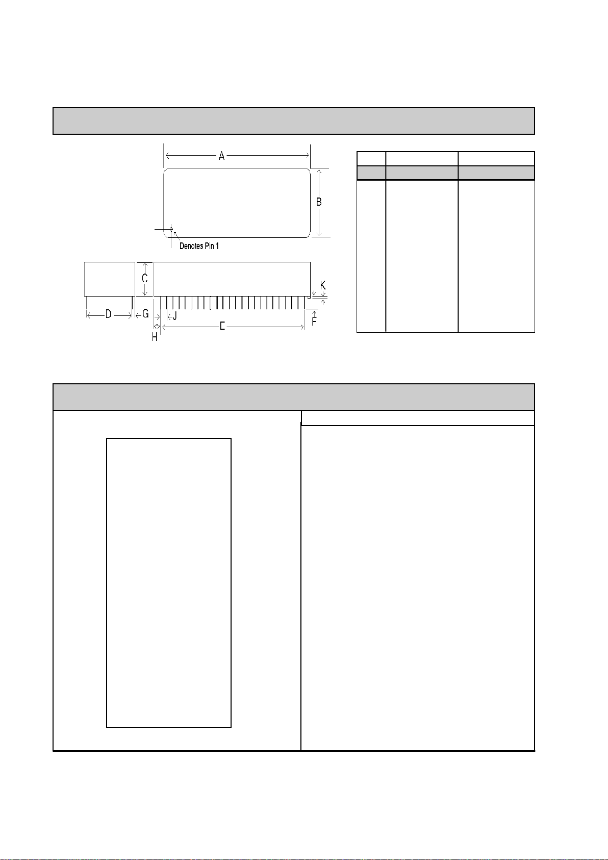
Mechanical Specifications
DIM MIN MAX MIN MAX
A 2.740 2.760 69.60 70.10
B 1.370 1.390 34.80 35.31
C 0.500 0.510 12.70 12.95
D 1.190 1.210 30.23 30.73
E 1.890 1.910 48.01 48.51
F 0.125 0.200 03.18 05.08
G 0.080 0.100 02.03 02.54
H 0.415 0.435 10.54 11.05
J 0.090 0.110 02.29 02.79
K 0.020 0.025 00.51 00.64
INCHES METRIC (MM)
Pin Configuration & Descriptions
1 48
2 Tele-Controller 47
3 46
4 45
5 44
6 43
7 42
8 41
9 40
10 39
11 38
12 37
13 36
14 35
15 34
16 33
17 32
18 31
19 30
20 29
21 28
22 27
23 26
24 25
TIP
RING
N/P
OH
SPKR
/SLEEP
N/C
V.bat
RXD
TXD
RESET
/EW
/INT0
T0
CNFG0
CNFG1
CNFG2
DIO0
DIO1
DIO2
DIO3
DIO4
DIO5
GND
VCC (5V)
DIO15
DIO14
DIO13
DIO12
DIO11
DIO10
DIO9
DIO8
DIO7
DIO6
DA1
DA0
A.VCC
ADI.7
ADI.6
ADI.5
ADI.4
ADI.3
ADI.2
ADI.1
ADI.0
STADC
A. GND
PIN SIGNAL DESCRIPTION
Page 3

8 V.bat V.bat provides backup power for the
real time clock. Battery voltage must
be at least 3 volts. A "Super Cap,"
NEC FYH0H473Z or equivalent, may
be used in place of a battery.
9 RXD RXD is the serial data input to the
Tele-Controller. A Mark or Logic 1 is a
TTL low; Space is a TTL high.
10 TXD TXD is the serial data output from the
Tele-Controller. A Mark or Logic 1 is
a TTL low; Space is a TTL high.
11 Reset Reset is an active high input to the
Tele-Controller. A high on Reset
initiates a hardware reset . This pin
acts as a Reset ouptut when the TeleController's watchdog timer expires.
12 /EW This active low input enables the
Tele-Controller's watchdog timer and
disables Sleep mode. When not used
this pin must be tied to VCC.
13 /INT0 This active low input acts as an
external interrupt to the TeleController.
14 T0 This active high input provides the
trigger for timer 0.
15 CNFG0 CNFG0 selects Tele-Controller
development or application mode. A
high selects application mode; a low
selects development mode.
16-17CNFG1-2 These inputs select the memory
address configuration of the ROM and
Flash memory. See the charts on
Pages 5 and 6 of this data sheet for
details on how these signals interact.
18-23 DIO0-5 Digital Input/Output Port 1 bits 0-5.
These signals are part of an 8-bit
digital I/O port. If the real-time clock is
to be used, bits 0-2 are needed to
support it. Port 1 alternate functions
include:
bit 0-3 - Capture inputs for timer T2
bit 4 - T2 event input
bit 5 - T2 Timer reset
24 GND GND provides digital ground to the
Tele-Controller.
25 A.GND A.GND provides analog ground for the
Analog inputs to the Tele-Controller.
26 STADC This active high input intiates an
analog to digital conversion. The
analog to digital conversion may also
be started through software.
27-34 ADI.0-7 8-channel Analog or Digital Input port.
This input port can be used as an
input port for digital data, or as inputs
to the analog to digital convertor.
35 A.VCC +5 Volt power for the analog inputs to
the Tele-Controller.
36-37 DA0-1 Pulse Width Modulation Outputs 1 and
2.
38-39 DIO6-7 Digital Input/Output Port 1 bits 6-7.
Port 1 alternate functions include:
bit 6 - I2C bus Serial Port Clock Line
bit 7 - I2C bus Serial Port Data Line
40-47 DIO8-15 Quasi bi-directional Digital
Input/Output Port 2 bits 0-7.
48 VCC +5 Volt power for the Tele-Controller.
XE5224DM & XE5224FD (3) XECOM
PIN SIGNAL DESCRIPTION PIN SIGNAL DESCRIPTION
Pin Descriptions (continued)
Page 4
XECOM (4) XE5224DM & XE5224FD
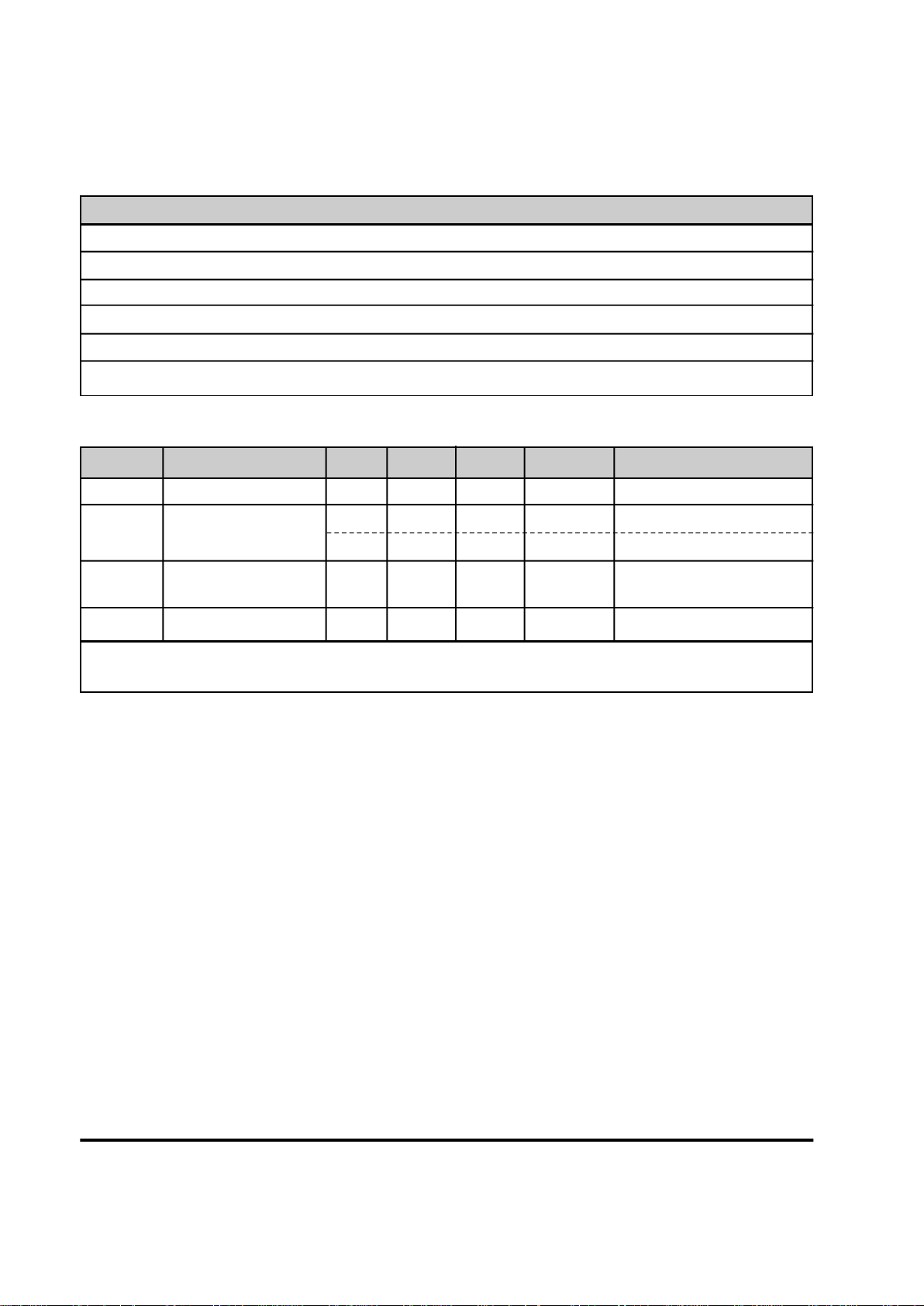
ABSOLUTE MAXIMUM RATINGS*
Electrical Specifications
* The modem in the XE5224DM or XE5224FD will automatically enter sleep mode if no activity is detected on the
TXD, DTR, or RI lines for 5 seconds. In sleep mode the modem typically draws less than 10 milliAmps.
SUPPLY VOLTAGE - Vcc +6.5 Volts
DC INPUT VOLTAGE -0.5 Volts to +6.5 Volts
STORAGE TEMPERATURE RANGE -25° C TO +100° C
LEAD TEMPERATURE (Soldering, 2 sec per wave) 260° C
OPERATING TEMPERATURE RANGE 0 TO 70° C (-40 to +85° C available by special order)
*Exceeding these values may result in permanent damage to the device.
Symbol Parameter Min Typ Max Units Comments
Vcc Supply Voltage 4.75 5.0 5.25 Volts
Icc Vcc Supply Current 55 milliAmps Modem in sleep mode *
95 milliAmps Modem On-Line
V.Bat Battery Voltage 3.0 Volts Real-Time Clock Battery
Backup
I.Bat Battery Current Draw 0.2 3.0 microAmps
Power Supply Characteristics(Vcc = 5v ± 5%)
Page 5

XE5224DM & XE5224FD (5) XECOM
Tele-Controller Memory Configuration
Memory Structure:
Xecom based the memory structure of the TeleController on the 8051 micro-controller. The lower
32 Kbyte memory addresses include separate
program and data storage. Program and data
storage overlap in the upper 32 Kbytes of memory.
The XE5224DM and XE5224FD Tele-Controllers
have 32 Kbytes of ROM, 32 Kbytes of RAM and
128 Kbytes of Flash memory. ROM contains the
code for Tele-Controller operation and software
design tools; RAM provides space for data storage
by the application program; the 128 Kbytes of Flash
memory can store data and/or application programs.
Flash memory is divided into four, 32 Kbyte pages.
Memory mapping permits shuffling ROM and Flash
memories within the standard 8051 memory
structure. Reconfiguring the Tele-Controller's
memory creates two modes of operation. In
development mode the code in ROM runs the
system. In application mode the application stored
in Flash memory operates the system.
Memory Mapping:
The Tele-Controller insures maximum flexibility with
a configurable memory mapping scheme. Three
external configuration pins select how the memory is
to be used. These three configuration pins, CNFG0,
CNFG1, and CNFG2, can be controlled by output
pins of the XE5224 or by board-mounted jumpers or
switches.
Development Mode:
Develoment mode uses the lower 32 Kbytes of
embedded ROM as program memory. ROM
addresses are 0 to 7FFFF. The lower 32 Kbytes of
data memory are dedicated to RAM except for the
small portion reserved for I/O lines. RAM provides
the Data memory for addresses 0 to 7EFF.
Addresses 7F00 to 7FFF serve peripheral I/O lines.
The upper 32 Kbytes of memory, addresses 8000 to
FFFF, access one of the four pages of Flash
memory. The CNFG1 and CNFG2 configuration
lines selects which page of Flash memory is
addressed. Table 1 shows Tele-Controller memory
mapping in development mode.
Application Mode:
In the application mode a page of Flash memory
serves as the lower 32 Kbytes of program memory.
This page of Flash memory is write protected. As
in the development mode, RAM provides the Data
storage in addresses 0 to 7EFF. Addresses 7F00 to
7FFF are provided for peripheral I/O lines.
The upper 32 Kbytes of memory, addresses 8000 to
FFFF, access page 1 or 3 of Flash memory. If the
application program is stored in either of these
pages, the user may choose to write protect this
page of memory as well. CNFG1 and CNFG2
configuration lines select Flash memory pages and
write protection as shown in Table 2 on the following
page.
Program Memory Data Memory Program/Data
CNFG2 CNFG1 0 - 7FFF 0 - 7EFF 7F00 - 7FFF 8000 - FFFF
0 0 ROM RAM Peripheral I/Os Flash Memory, Page 0
0 1 ROM RAM Peripheral I/Os Flash memory, Page 1
1 0 ROM RAM Peripheral I/Os Flash memory, Page 2
1 1 ROM RAM Peripheral I/Os Flash memory, Page 3
Table 1 Development Mode Memory Mapping (CNFG0=0)
Page 6
XECOM (6) XE5224DM & XE5224FD
Tele-Controller Memory Configuration continued
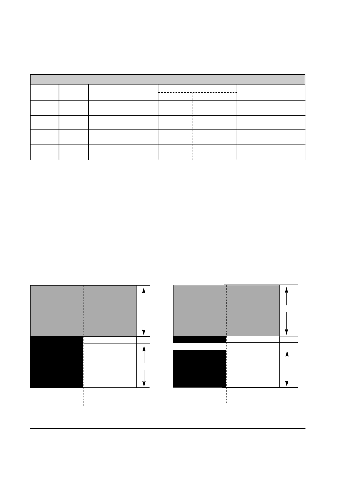
Program Memory Data Memory Program/Data
CNFG2 CNFG1 0 - 7FFF 0 -7EFF0 7F00 - 7FFF 8000 - FFFF
0 0 Flash Memory, Page 0 RAM Peripheral I/Os Flash Memory, Page 1
(write protected)
0 1 Flash Memory, Page 0 RAM Peripheral I/Os Flash Memory, Page 1
(write protected) (write protected)
1 0 Flash Memory, Page 2 RAM Peripheral I/Os Flash Memory, Page 3
(write protected)
1 1 Flash Memory, Page 2 RAM Peripheral I/Os Flash Memory, Page 3
(write protected) (write protected)
Table 2 Application Mode Memory Mapping (CFG0=1)
Overlapped Memory:
Data and Program memory share the upper half of
the available memory, addresses 8000 to FFFF.
This area can be accessed as either Program or
Data memory. When downloading Program code
into the XE5224, the code must be stored as Data in
addresses 8000 to FFFF. When the download is
complete, you can access this code as Program
memory because of the memory overlap.
Flash memory may store both user data and the
application program; however, because all pages of
Flash memory are physically located in one device,
you cannot simultaneously read and write from
Flash memory. When the application program must
manipulate stored data, a portion of RAM must be
used as program memory. Memory locations
locations 7E00 to 7EFF overlap RAM and Flash
memory in the Application mode. Reserve these
memory locations for subroutines which require
manipulation of the stored data.
SRAM
(32K)
Program Data
Memory Memory
EPROM
(32K)
Development Mode
8000 - FFFF
Program & Data
Memory Overlap
(32K)
Flash Memory Page 1, 2, 3 or 4
0 - 7EFF
Reserved for Peripheral I/0
SRAM
(32K)
Program Data
Memory Memory
Flash Memory
Page 0 or 2
(32K)
Application Mode
8000 - FFFF
Program & Data
Memory Overlap
(32K)
Flash Memory Page 1 or 3
0 - 7DFF
Reserved for Peripheral I/0
RAM Overlap Addresses 7E00 to 7EFF
Memory Overlap
Page 7

ROM:
Tele-Controller ROM holds the TC-Monitor and
Tele-Monitor programs to assist in application
development. These programs operate only in
Development mode. These design tools permit the
user to down-load his application program to Flash
memory from either the embedded modem or Serial
Port, edit Flash memory contents, run Analog/Digital
conversions, set and display the Real-Time Clock,
and execute the application program. TC-Monitor
and Tele-Monitor operations are described in detail
elsewhere in this data sheet.
RAM:
32 Kbytes of RAM are primarily used for data
storage by the application program. The
addressable range is from 0 to 7EFF. Addresses
7E00 to 7EFF overlap with program memory in the
Application mode. These locations should be used
for subroutines which need to access data stored in
Flash memory. Addresses 7F00 to 7FFF are
reserved for peripheral I/O use in both Development
and Application mode.
Flash:
Flash memory provides 128 Kbytes of non-volatile
storage for data and/or application programs. Flash
memory is divided into four, 32 Kbyte pages to fit in
the 8051 memory structure. The 128 Kbytes of
Flash memory are contained in one memory chip
within the XE5224.
In Development mode Flash memory is addressed
as the upper 32 Kbytes of overlapped memory,
addresses 8000 to FFFF. The CNFG1 and CNFG2
control lines determine which page of Flash memory
is being addressed.
In Application mode program code may be stored in
any page or pages of Flash memory. Data may be
stored only in Flash memory pages 1 and 3. Again
CNFG1 and CNFG2 control the configuration of
Flash memory. Pages of Flash Memory used for
program storage are write protected.
XE5224DM & XE5224FD (7) XECOM
Tele-Controller Memory Configuration continued
Page 8

XECOM (8) XE5224DM & XE5224FD
TC-Monitor
Access to the TC-Monitor is through the TeleControllers's serial interface. Connect a PC to the
Tele-Controller's and using a terminal emulation
program press <Enter>. The Tele-Controller will
respond with the prompt "TC-Monitor."
When the TC-Monitor prompt is present pressing
<Enter> causes the Tele-Controller to display the TCMonitor command list. Table 3 provides descriptions
of the TC-Monitor commands. Parameters shown in
brackets [ ] are optional; parameters shown in
parenthesis are required.
Analog Input Fill Memory Kill Memory Output Data UART
Change Data Go To Program Load Program Read Format File Version
Display Program Help Move Program Show Write Hex File
Examine Memory Input Next Time
TC-Monitor Commands
Tele-Monitor Commands
Tele-Controller ROM Based Monitor/Debugger
The Tele-Controller contains a pair of application
debugging tools in ROM. The TC-Monitor permits
applications testing and memory alterations through
the Tele-Controller's serial interface. The TeleMonitor permits remote control of many of the same
functions via the Tele-Controller's modem link. Both
programs operate only in the Development mode.
Both the TC-Monitor and Tele-Monitor use single
character commands. The first parameter
associated with a command does not require any
spacing characters; however, you may insert a
comma, space, period or colon to improve ledgibility.
When you enter address locations in either monitor
program, any digits missing from the address are
asumed to be zeros to the left of the most signifigant
digit shown.
Tele-Monitor
Access to the Tele-Monitor is through the TeleControllers's internal modem. In development mode
you immediately enter the Tele-Monitor when the
modem establishes a data link. The Tele-Controller
provides a Tele-Monitor prompt when the link is
established.
The Tele-Monitor operates the same way as does the
TC-Monitor. There are some commands which are
unique to the Tele-Monitor. The list of Tele-Monitor
commands is shown above. Tele-Monitor commands
are desribed in table 4.
Analog Input Fill Memory Kill Memory Output Data
Change Data Go To Program Load Program Read Format File Version
Display Program Help Move Program Show Write Hex File
Examine Memory Input Time eXit
Page 9

XE5224DM & XE5224FD (9) XECOM
Analog Input A [x]<ENTER> This command causes theTele-Controller to read the
designated Analog I/O channel. If no channel is designated,
all channels are read. The Analog to Digital convertor uses a
5 volt reference with 10 bit resolution. A value of 3FFH
indicates 5.0 volts is present on the I/O channel. A value of
200H indicates 2.5 volts. Press the space bar to read the
analog input. Pressing a C causes the Tele-Controller to
continuously read the analog input. Pressing Alt C ends the
continuous reading of the analog input.
Change Memory C (word -- address)<ENTER> This command allows you to modify the contents of an
individual memory cell. When you enter this command, the
Tele-Controller displays the byte stored in the selected
memory location. Type the new value in this location and
press Enter. The Debugger will advance to the next memory
location. To exit the change mode without altering the
contents of the current address press Enter. To advance to
the next address without altering the memory contents hit the
space bar followed by Enter.
Display Data D (Address1)(Address 2) <ENTER> This command is used to display the contents of an area of
data memory. The two addresses define the area. Address 1
is the starting address and Address 2 the ending address. If
Address 1 is greater than Address 2, the Tele-Controller will
upon reaching Address FFFF return to address 0 and
continue to display the memory contents until reaching
Address 2. When used to display the contents of a section of
overlapped memory, this command acts the same as the "E"
command.
Examine Program E (Address1)(Address 2) <ENTER> Display the contents of an area of program memory. The two
addresses define the area. Address 1 is the starting address
and address 2 the ending address. If Address 1 is greater
than Address 2, the Tele-Controller will upon reaching
Address FFFF retrun to address 0 and continue displaying the
memory contents until reaching Address 2. When used to
display the contents of a section of overlapped memory, this
command acts the same as the "D" command.
Fill memory F (Add.1)(Add.2) (Bytes) <ENTER> This command fills the selected memory area with the listed
values.
Go to program G [=Add][Add.] This command allows you to execute an application program
currently in memory. After this command is entered system
control is transferred to the application program. An "LJMP 0"
command must be placed in the application program to return
to the TC-monitor.
Help Messages H<ENTER> The "H" command causes the TC-Monitor to display its help
screen as shown below.
-----------------------------------------------------------------------------| - Press<Enter> for the Command list |
| - For the correct command syntax insert "?" after the |
| command, for instance D?. Parameters shown in |
| parenthesis ( ) are required; parameters shown in |
| brackets [ ] are optional. |
| - Memory addresses are in hexadecimal form. |
------------------------------------------------------------------------------
Command Syntax Description
Table 3: TC-Monitor Commands
Page 10

XECOM (10) XE5224DM & XE5224FD
Input I(Port Address) Inputs one byte specified by (Port Address). Entering a space
inputs one byte; a C causes bytes to be continuously entered.
A Carriage Return terminates the continuous mode.
Kill Memory K(n) <ENTER> This command erases the designated sector of Flash
memory. Only sectors of Flash memory which are not write
protected may be erased. The message "Unkown memory
section or write protected" will be displayed if you attempt to
erase a protected area of memory.
Load Program L(Source Start Add)(Source End Add) This command loads the data from the designated
(Target Start Add)<ENTER> program memory location into the selected data memory
address.
Move Program M(Source Start Add)(Source End Add) The "M" command moves a block of data from one data
(Target Start Add)<ENTER> memory address to another.
Next N [Add]<Enter> This command permits you to step through your application
program one instruction at a time. Step from one instruction
to the next by pressing the space bar. Enter a Carriage
Return to exit single-step operation.
Output Data O(I/O Address) (byte)<ENTER> Output the indicated byte to the selected I/O address.
Read File R[Offset Address] <ENTER> The "R" command permits .Hex files to be downloaded from
the host, normally a Personal Computer. This command may
be ommited if a zero offset address is needed.
Show S[Register]<ENTER> This command displays the contents of the listed register. If
no register value is listed, the contents of all registers will be
displayed.
Time T<ENTER> This command is used to start the Tele-Controller's Real
Time Clock. The TC-Monitor first asks if you wish to Reset
the Real Time Clock; enter Y for yes and N for no. If you
enter No, you will return to the TC-Monitor prompt. If you
select Yes the TC-Monitor will prompt you to enter a new
Year, Month, Day, Hour and Minute.
UART U<ENTER> This command permits direct communications with the
modem. This permits you to enter "AT" modem commands
directly to the modem by using terminal emulation software.
To end communications with the modem type the # character
followed by <ENTER>.
Version V<ENTER> This command displays the revision level of the TC-Moniltor.
The format will be "V 1.00-ROM, Xecom, 10/10/94. Note: If
you are using an updated version of the TC-monitor stored in
Flash memory the revision level will be shown as V 1.xxFlash, Xecom, 1/1/95.
Write Hex File W(Start Add) (End Add) <ENTER> This command is used to upload the contents of the program
memory in the controller to the host. To upload contents of
data memory into program memory it must first be loaded
into an overlapped memory section. If the listed starting
address is greater than the ending address, the TC-Monitor
will roll over to address zero when completed with address
FFFF and continue until the ending address is reached.
Command Syntax Description
Table 3 (continued)
Page 11

Analog Input A [x]<ENTER> Same as TC_monitor
Change Memory C (word -- address)<ENTER> Same as TC_monitor
Display Memory D (Address1)(Address 2) <ENTER> Same as TC_monitor
Examine Memory E (Address1)(Address 2) <ENTER> Same as TC_monitor
Fill memory F (Add.1)(Add.2) (Bytes) <ENTER> Same as TC_monitor
Go to program G(=Add)(Add.) Same as TC_monitor
Help Messages H<ENTER> Same as TC_monitor
Input I(Port Address) Same as TC_monitor
Kill Memory K[n) <ENTER> Same as TC_monitor
Load Program L(Source Start Add)(Source End Add) Same as TC_monitor
(target start add)<ENTER>
Move Program M(Range)(Add.) Same as TC_monitor
Output Data O[I/O Address] [byte]<ENTER> Same as TC_monitor
Read Format File R[Offset Address] <ENTER> Same as TC_monitor
Show S<ENTER> Same as TC_monitor
Time T<ENTER> Same as TC_monitor
Version V<ENTER> Same as TC_monitor
Write Hex File W(Start Add)(End Add) <ENTER> Same as TC_monitor
eXit X<ENTER> This command causes the Tele-Controller to drop the modem
link .
Command Syntax Description
Table 4: Tele-Monitor Commands
XE5224DM & XE5224FD (11) XECOM
Page 12
XECOM (12) XE5224DM & XE5224FD
Modem Description
Xecom's Tele-Controller includes an integral modem. The XE5224DM supports data transfer up to 2400 bits
per second; the XE5224FD adds 9600 bps send fax and 4800 bps receive fax. Modem control is by industry
standard AT commands. The modem includes non-volatile memory for modem configuration storage.
The TC-Monitor's "U" command permits the developer to enter "AT" commands directly to the internal
modem through the Tele-Controller's RS232 port. The Tele-Controller accepts the initial input at rates from
300 to 38,400 bits per second. Subsequent commands can only be issued at the same speed as the intial
input. Only 10 bit characters will be accepted. Parity may be Even, Odd, Mark, Space or None.
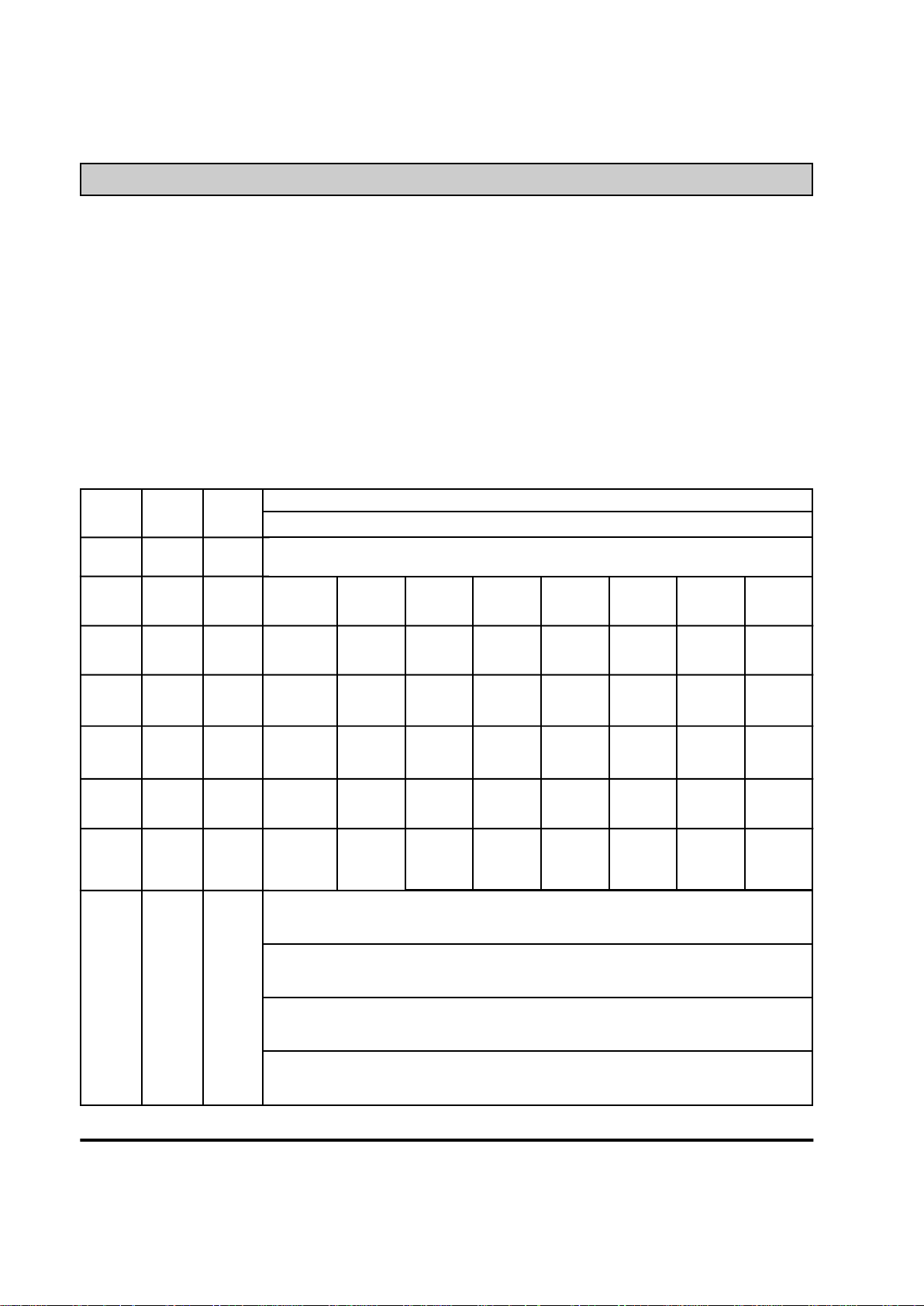
The modem-controller interface is a 16C450 compatible parallel interface. Modem registers 0 through 7 are
addressed using addresses 7F00 through 7F07. The chart below describes the register functions.
Register
7
6
5
4
3
2
1
0
DLAB=0
0
DLAB=0
0
DLAB=0
0
DLAB=0
Address
7F07
7F06
7F05
7F04
7F03
7F02
7F01
7F00
7F00
7F00
7F00
Name
Scratch
(SCR)
Modem
Status
(MSR)
Line
Status
(LSR)
Modem
Control
(MCR)
Line
Control
(LCR)
Interrupt
ID
(IIR)
Interrupt
Enable
(IER)
Transmit
Holding
(THR)
Receive
Buffer
(RBR)
Divisor
Latch MSB
(DLM)
Divisor
Latch LSB
(DLL)
7 6 5 4 3 2 1 0
Bit No.
Data Carrier
Detect
(DCD)
0
0
Divisor Latch
Access Bit
(DLAB)
0
0
Ring
Indicator
(RI)
Transmitter
Empty
(TEMT)
0
Set Break
0
0
Data Set
Ready
(DSR)
Transmitter
Holding Reg.
(THRE)
0
Stick Parity
0
0
Clear to
Send
(CTS)
Break
Interrupt
(BE)
Local
Loopback
Even Parity
Select
(EPS)
0
0
Delta Data
CXR Detect
(DDCD)
Framing
Error
(FE)
Out 2
Parity
Enable
(PEN)
0
Modem
Status
Interrupt
(EDSSI)
Trailing Edge
of RI
(TERI)
Parity Error
(PE)
Out1
Number of
Stop Bits
(STB)
Pending
Interupt ID
Bit 1
Enable Rx
Line Status
Interrupt
(ELSI)
Delta Data
Set Ready
(DDSR)
Overrun
Error
(OE)
Request
to Send
(RTS)
Word Length
Select Bit 1
(WLS1)
Pending
Interrupt ID
Bit 0
Enable Tx
Holding Reg.
Empty Int.
(ETBEI)
Delta Clear
to Send
(DCTS)
Data Ready
(DR)
Data
Terminal
Ready (DTR)
Word Length
Select Bit 0
(WLS0)
"0" if
Interrupt
Pending
Enable RXD
Availible Int.
(ERBFI)
Scratch Register
Transmitter Holding Register (Write Only)
Transmitter Holding Register (Read Only)
Divisor Latch (MS)
Divisor Latch (LS)
Modem Registers
Page 13
Modem Registers
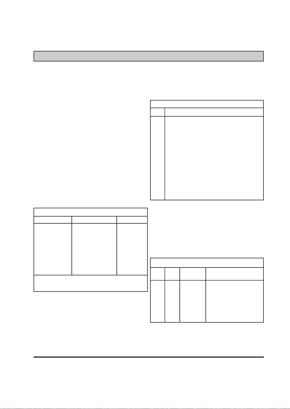
The modem inside either Tele-Controller, XE5224DM
or XE5224FD, interfaces to the embedded controller
via eight registers. Each of these registers is
described below.
Register 0: Data Holding Register
Register 0 has two functions. It operates as the data
buffer and sets the modem's baud rate.
Register 0 acts as the Transmit Holding Register and
the Receive Buffer Register. Bit 0 is the least
signifigant bit and the first bit transmitted or received
by the modem.
When the Divisor Latch Access Bit (Bit 3) of Register
3 is set, register 0 along with register 1 programs the
modem baud rate. Register 0 provides the least
signifigant byte and Register 1 the most signifigant
byte for the divisor latch. The Chart below shows
how each baud rate is selected
Register 1: Interrupt Enable Register
Register 1 also has two functions. It enables various
modem interrupts and in conjunction with Register 0
sets the modem's baud rate.
As described above Register 1 works in combination
with Register 0 to set the modem baud rate. Note
that baud rates above 2400 bits per second can be
used only for fax operation.
When Register 1 is used to enable interrupts, Bits 0
to 3 select the modem conditions which will cause an
interrupt. The chart below describes these interrupts
and indicates which bit selects each of them.
Register 2: Interrupt Identification
Register
Register 2 shows if any interupts are active and
identifies the active interrupt with the highest priority.
Bit 0 goes active to indicate the presence of an
interrupt. Bits 1 and 2 show the active interrupt with
the highest priority. The chart below shows the
priority code and level for the interrupts.
XE5224DM & XE5224FD (13) XECOM
Modem Register Descriptions
Divisor Latch
MS LS Divisor (decimal) Baud Rate
01 80 384 300
00 C0 192 600
00 60 96 1200
00 30 48 2400
00 18 24 4800*
00 0C 12 9600*
00 06 6 19,200**
* Fax Mode Only
* Fax Command Mode Only
Interrupts Enabled
Bit Interrupt Enabled
0 Received Data Available: Indicates that the
Receive Buffer Register, Register 0, has
data to send to the controller.
1 Transmit Holding Register Empty: indicates
Register 0 can accept another byte of data
for transmission.
2 Line Status Register: indicates a change in
one of the bits of Register 5, Line Status.
3 Modem Status Register: indicates a change
in one of the bits of Register 6, Modem
Status.
Interrupt Priorities
Priority
Bit 2 Bit 1 Level Active Interrupt
1 1 highest Receiver line Status
0 1 second Receiver Buffer Full
1 0 third Transmitter Holding
Register Empty
0 0 lowest Modem Status
Page 14

Register 3: Line Control Register
Register 3 determines the asynchronous data format
expected by the modem. Format parameters include
character length, parity, stop bits, Break transmision
and Data Rate.
Bit Description
0,1,2 Bits 0,1 and 2 select the character length.
Bit 2 selects the number of stop bits.
Refer to the table below.
3,4,5 Bits 3, 4, and 5 select the data parity. The
table below illustrates the various parity
settings.
6 Bit 6 forces the modem to transmit a break
signal or continuous space (logic 0). Bit 6
must be reset to logic 0 to disable break.
7 Bit 7 sets the Divisor Latch which permits
registers 0 and 1 to set the modem data
rate. (see description on page 13)
Register 4: Modem Control Register
Register 4 controls the modem-controller interface. It
also selects the local loopback diagnostic.
Bit Description
0 A logic 1 on bit 0 activates DTR
1 A logic 1 on bit 1 activates RTS
2 Bit 2 controls the OUT1 signal.
3 Bit 3 controls the OUT2 signal.
4 Bit 4 selects the local loopback diagnostic.
Data written into the Transmit Holding
Register will be looped through the modem
back to the Recevier Buffer Register.
5-7 not used
Register 5: Line Status Register
Register 5 provides data status information on the
modem. Status of the Transmitter and Reciever as
well as error indications are provided.
Bit Description
0 Bit 0 goes true whenever the Receiver
Buffer Register contains a complete
received character.
1 Bit 1 indicates data in the Receiver Buffer
Register was over written.
2 Bit 2 indicates the occurance of a parity
error in the received character.
3 Bit 3 indicates the received character did
not have a vaild stop bit.
4 Bit 4 indicate the continuous receipt of a
space for more than two word lengths.
Continuous space indicates presence of
a break signal.
5 Bit 5 indicates the modem can accept the
next character for transmission.
6 A logic 1 in Bit 6 indicates both the
Transmitter Holding Register and
Transmitter Shft Register are empty.
7 Not Used
XECOM (14) XE5224DM & XE5224FD
Bit 0 Bit 1 Bit 2 Character Format
0 0 0 5 bits, 1 stop bit
1 0 0 6 bits, 1 stop bit
0 1 0 7 bits, 1 stop bit
1 1 0 8 bits, 1 stop bit
0 0 1 5 bits, 2 stop bits
1 0 1 6 bits, 2 stop bits
0 1 1 7 bits, 2 stop bits
1 1 1 8 bits, 2 stop bits
Bit 3 Bit 4 Bit 5 Character Format
0 X X No Parity
1 0 0 Odd Parity
1 1 0 Even Parity
1 0 1 Parity Bit Equals 1
1 1 1 Parity Bit Equals 0
Modem Register Descriptions (continued)
Page 15

Register 6: Modem Status Register
Register 6 indicates the modem's current status.
Data Set Ready, Clear to Send, Ring Indication and
Carrier Detect are all monitored.
Bit Description
0 Delta Clear to Send: A logic 1 indicates
the status of the Clear to Send signal has
changed since Register 6 was last read.
1 Delta Data Set Ready: A logic 1 indicates
the status of the Data Set Ready signal has
changed since Register 6 was last read.
2 Trailing Edge Ring Indicate: : A logic 1
indicates Ring Indicate has changed from a
1 to a 0 since Register 6 was last read.
3 Delta Data Carrier Detect: A logic 1
indicates the status of the Data Carrier
Detect signal has changed since Register 6
was last read.
4 Clear to Send: When Clear to Send is true,
the modem can accept data for
transmission.
5 Data Set Ready: Indicates the state of
Data Set Ready. Data Set Ready is true
when the modem has siezed the telephone
line.
6 Ring Indicate: Indicates the presence of a
ring on the telephone line.
7 Data Carrier Detect: When Data Carrier
Detect is true, a valid carrier signal has
been detected on the telephone line.
Register 7: Scratch Pad Register
Register 7 is not used by the modem. You can both
read and write from Register 7. It can be used by the
controller for temporary storage.
XE5224DM & XE5224FD (15) XECOM
Modem Register Descriptions (continued)
Page 16

XECOM (16) XE5224DM & XE5224FD
AT Commands
Modes of Operation
The modem within the Tele-Controller responds to
standard "AT" commands. It includes three
operational modes; Command Mode and Data
Modes plus an extension for Fax operation.
Data Mode: The modem enters data mode after it
connects with a remote modem and issues the
"CONNECT" result code. In Data Mode the modem
sends all signals on Transmit Data to the remote
modem and directs data from the remote modem
onto Received Data. When the modem exits data
mode, it issues the "NO CARRIER" result code.
Command Mode: The modem enters command
mode on power-up, reset, a lost connection, or
receipt of the escape code. In the command mode
the modem accepts instructions from the host on
Transmit Data. Result codes are returned on
Received Data. "AT" commands allow the host to
configure the modem for a specific application.
Fax Mode: The command AT+FCLASS=1 puts the
modem in the XE5224FD into fax mode. The
modem issues fax commands and responses at
19,200 bits per second; 8 data bits and no parity.
The modem accepts only Class 1 fax commands.
The A/, ATO, AT&T and escape commands are not
valid in fax mode.
Command Line Format
Commands issued to the modem follow a strict
format. Each command line begins with the prefix
"AT". The modem stores the command line in the
command buffer and executes it upon receipt of a
carriage return. More than one instruction may be
placed in each command line.
Command Prefix - Each command, except the A/
command, begins with the "AT" prefix. The "A" and
"T" may be either both upper case or both lower
case but not mixed cases. The modem examines
the "AT" to determine the speed and parity of the
commands. The modem sends the result codes at
the same speed and parity as the last "AT"
command.
Command Line - The modem within the TeleController accepts up to 40 characters in a
command line. The modem executes the
commands in the sequence they appear within the
command line. A carriage return terminates the
command line and causes the commands to be
executed. Register S3 allows selection of a
character other than carriage return to terminate the
command line.
Command Buffer - No more than 40 characters,
including the "AT" prefix, may be loaded into the
command buffer. If the command buffer overflows,
the modem issues an "ERROR" result code and
commands are not executed.
Command Line Editing - You can edit the
command line any time before it is executed using
the backspace character. The backspace erases
the previous character in the command line. All of
the characters in the command line can be erased
except for the "A" and "T." Register S5 allows you
to select a character other than a backspace to edit
the command line.
Re-Execute Previous Command - The A/
command causes the modem to again execute the
previous command line. This is the only command
which does not use the "AT" prefix.
Ommitted Parameters - Most commands include a
parameter which determines how the functions will
be set. Command parameters may sometimes be
omitted from the command string. When the
parameter is ommitted it is assumed to be a 0.
Page 17

XE5224DM & XE5224FD (17) XECOM
Escape Characters - A 3 character escape
sequence may be entered from data mode. It
switches the modem into command mode without
dropping the line. The escape character, set by
Register S2, must be entered 3 times in succession
within 1 second to execute the escape. The default
escape sequence is "+++."
Result Codes - The modem issues a result code
after each action. The table of result codes appears
below. Result codes may be provided as full words,
numeric codes or may be disabled. Each result
code ends with a carriage return when numeric
result codes are chosen. When full word result
codes are chosen, a Line Feed and Carriage Return
preceed and follow each result code. The Line Feed
and Carriage Return characters may be altered with
Registers S4 and S5.
Non-Volatile Memory - The modem within the TeleController is supported by non-volatile memory.
Non-volatile memory protects modem configuration
and frequently dialed numbers when the modem
loses power. The values of the following commands
and registers are stored in non-volatile memory; Bn,
En, Ln, Mn, Qn, Vn, Xn, &Cn, &Dn, &Yn, and S0.
The modem's last speed, parity setting and escape
character are also stored in non-volatile memory.
0 OK Successfully executed command
1 CONNECT 300 bps connection established
2 RING Ring signal detected
3 NO CARRIER Carrier not detected or lost
4 ERROR Error found in command line;
returns to command mode
5 CONNECT 1200 1200 bps connection established
6 NO DIAL TONE No dial tone detected within 5
seconds after going off-hook
7 BUSY Busy signal detected after
automatically dialing a call
8 NO ANSWER 5 seconds silence not detected
10 CONNECT 2400 2400 bps connection established
13 DATA Automatically connected as a
data modem.*
+FX Fax connect error *
* XE5224FD only
DIGIT FULL DEFINITION
AT Commands continued
Page 18

XECOM (18) XE5224DM & XE5224FD
An asterisk (*) indicates the factory default value of
each command.
A - Answer Command -
Imediately initiates answer sequence
Bn - Select 1200 bps Communications Standard
n=0 Selects CCITT standards
n=1 Selects Bell standards *
D - Dial Command -
0-9, *, # Dial Digits
P = Pulse dial following digits
T = Tone dial following digits
R = Connect as an answering modem
Sn = Dial Stored Number, n=0-3
W = Wait for dial tone
, = Pause for the duration of S8
@ = Wait for silence
! = Switch hook flash
; = Return to the command state
En - Command Echo
n=0 Do not echo commands
n=1 Enable command echo *
Hn - Switch Hook Control -
n=0 Switch hook relay opens (on-hook) *
n=1 The switch hook relay closes (off-hook)
In - Modem Identification
Ln - Speaker Volume -
n=0 Low speaker volume
n=1 Low speaker volume
n=2 Moderate speaker volume *
n=3 High speaker volume
Mn - Speaker Activity -
n=0 Speaker off
n=1 Speaker on until carrier received *
n=2 Speaker remains on
n=3 Speaker on from the completion of dialing
until carrier detected
On - On Line
n=0 Return On Line with no retrain
n=1 Initiate retrain while returning On line.
Qn - Responses
n=0 Send responses *
n=1 No Responses
Sn? - Interogate Register n Sn=x - Set Register n to Value x Vn - Result Codes -
n=0 Numeric Result Codes
n=1 English Word Result Codes *
Xn - Result Code Set -
n=0 Connect result code enabled, no busy or
dial tone detection
n=1 CONNECT XXXX result code enabled, no
busy or dial tone detection.
n=2 No busy tone detection, CONNECT XXXX
result code
n=3 No dial tone detection, CONNECT XXXX
result code
n=4 Show all result codes *
Zn - Reset -
Perform a soft reset and return to profile n.
n=0 Return to stored profile 0 *
n=1 Return to stored profile 1
&Cn - DCD Operation
n=0 DCD is forced active. *
n=1 DCD indicates a valid carrier signal has
been detected
&Dn - DTR
n=0 DTR is ignored by the modem.
n=1 Go to command mode if the host revokes
DTR.
n=2 Modem disconnects if the host revokes
DTR.
n=3 The modem performs a soft reset when
DTR is revoked.
&F - Return to Factory Defaults
&Tn - Test Modes
n=0 Exit test mode
n=1 Local analog loopback
n=3 Initiate local digital loopback
n=4 Respond to remote loopback request *
n=5 Deny remote loopback request
n=6 Intiate a remote digital loopback
n=7 Remote digital loopback w self-test
n=8 Local analog loopback w self-test
&V - View Active Profile -
AT Command List
Page 19

XE5224DM & XE5224FD (19) XECOM
&Wn - Stored Active Profile
n=0 Store as Profile 0 *
n=1 Store as Profile 1
&Yn - Active Profile on Power-Up
n=0 Recall Profile 0 *
n=1 Recall Profile 1
&Zn = x - Store number "x" in location "n"
n= 0-3
+FAA = n - Data/Fax Auto-Answer
n=0 Answer according to FClass setting *
n=1 Automatic determination of data or fax call
+FCLASS=n - Set Service Class
n=0 Configured as a data modem
n=1 Configured for Service Class 1.
+FCLASS=? - Available Service Class
+FCLASS? - Current Service Classes
+FTS=n - Transmit Silence
(selectable in 10 millisecond increments)
+FRS=n - Receive Silence
(selectable in 10 millisecond increments)
+FTM=n - Transmit Fax
n=24 V.27ter at 2400 bps
n=48 V.27ter at 4800 bps
n=72 V.29 at 7200 bps
n=96 V.29 at 9600 bps
+FRM<n> - Receive Fax
n=24 V.27ter at 2400 bps
n=48 V.27ter at 4800 bps
+FTH<n> - Transmit HDLC Data
n=3 V.21 Channel 2
+FRH<mod> - Receive HDLC Data
n=3 V.21 Channel 2
Class 1 Fax Command List
Below are the descriptions of the Class 1 fax commands, EIA 578. These commands are used to control fax
operation in Xecom's send and recieve fax & data modems.
AT Command List (continued)
Page 20

XECOM (20) XE5224DM & XE5224FD
S Registers
Some of the modem configuration is stored within registers inside the modem. The contents of these
registers can be read with the ATSn? command where Sn is the register being interogated. The register
contents can be modified with the ATSn=x where Sn is the register to be changed and x is the new value.
Below are descriptions of the commonly used registers in the XE5224FD and XE5224DM.
Register Definition
S0 Answer on nth Ring: S0 Settings from 1 to 255 cause the modem to automatically answer on
that number of rings. If S0 is set to 0 the modem will not automatically answer an incoming call.
The value stored is S0 can also be stored in non-volatile memory.
S1 Ring Count: S1 is a read-only register. It carries the number of rings detected from 0 to 255. If
no ring is detected for 8 seconds, the counter is reset to zero.
S2 Escape Character: S2 determines the ASCII character used in the escape sequence. Values of
0-127 are valid ASCII escape characters; values from 128 to 255 disable the escape sequence.
S3 Carriage Return Character: S3 determines the ASCII character used as a carriage return to
terminate commands and to be used in modem responses.
S4 Line Feed Character: S4 determines the ASCII character to be used as a line feed character in
modem responses.
S5 Back Space Character: S5 determines the ASCII character used as a backspace to edit the
command line. Only values from 0 to 32 will be accepted.
S6 Dial Tone Wait Time: S6 determines how long the modem waits for dial tone before dialing
begins. The value in S6 sets the delay in seconds. Values from 0 to 255 are accepted; however,
the modem always waits at least two seconds.
S7 Wait for Carrier after Dialing: S7 determines how long the modem will wait to detect a valid
carrier signal after dialing is completed. The value in S7 sets the wait in seconds. Values from 1
to 255 are accepted
S8 Comma Pause Time: S8 sets the duration of the pause in dialing caused by a comma in the
dialing string. The pause is generally used when waiting for a second dialtone. Values of from 1
to 255 set the pause time from 1 to 255 seconds.
S9 Carrier Detect Response Time: S9 establishes the length of time the remote modem's carrier
must be present to be recognized as valid. Values from 1 to 255 set the response time in .1
second intervals.
S10 Carrier Off Disconnect Delay: S10 determines how long the remote modem's carrier must be
lost before the local modem disconnects. Values from 1 to 255 set this delay in .1 second
intervals. Note: If the value of S10 is smaller than the value of S9, the modem will not
automaticlly disconnect when carrier is lost.
S11 Tone Dialing Speed: S10 sets the duration and spacing of the dialing tones. Values of S11 from
50 to 255 set both the tone duration and the interval between tones in milliseconds. Note: the
pulse dialing rate is not affected by S11.
Page 21
XE5224DM & XE5224FD (21) XECOM
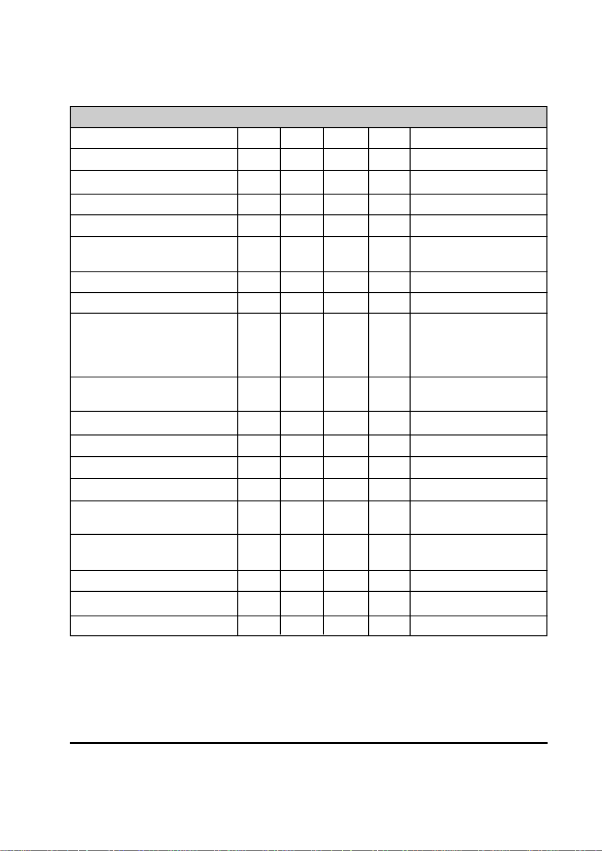
PARAMETER MIN TYP MAX UNIT COMMENTS
DTMF Level -2.2 0 dBm
DTMF Twist (Balance) 3 dB
DTMF Tone Duration 70 ms
Pulse Dialing Rate 10 pps
Pulse Dialing Make/Break 39/61 % USA
33/67 % CCITT
Pulse Interdigit Interval 785 ms
Billing Delay Interval 2.0 sec.
Guard Tone Frequency 550 Hz Referenced to high
Amplitude -3 dB channel transmit
Frequency 1800 Hz
Amplitude -6 dB
High Channel Transmit Amplitude -1 dB Referenced to low channel
guard tone
Tone Detection Bandpass Frequency 290 665 Hz 3 dB point
Tone Detection OFF to ON Threshold -33 dBm into 600 ohms
Tone Detection ON to OFF Threshold -35 dBm into 600 ohms
Dial Tone Detect Duration 3.0 sec.
Ringback Tone Detect Duration 0.75 sec.
Cadence 1.5 sec. OFF/ON Ratio
Busy Tone Detect Duration 0.2 sec.
Cadence 0.67 1.5 sec. OFF/ON Ratio
Telephone Line Impedance Match 600 ohms
Ring Detect Sensitivity 38 Vrms Type B ringer
Telephone Line Holding Current 20 100 mA
Modem Specifications
Page 22

XE5224DM & XE5224FD (22) XECOM
FCC Instructions
FCC Registration Number:
XE5224DM DWEUSA-21876-MD-E Ringer Equivalence: 0.7B
XE5224FD DWEUSA-75322-FA-E Ringer Equivalence: 0.8B
This product complies with Part 68 of the FCC Rules and Regulations. Each device shipped includes a label which
contains the FCC Registration Number and Ringer Equivalence (REN). If requested, this FCC information must be
provided to the telephone company. A registration label must be affixed to the cabinet's exterior for each device mounted
within a closed assembly.
Ringer Equvalence (REN) is used to calculate the number of devices you may connect to one telephone line and still
have all of the devices respond to an incoming call. Typically, the sum of the RENs of all devices connected to one line
should not exceed five (5.0). Contact your local telephone company to determine the maximum REN for your area.
Mount this device in the final assembly so as to prevent exposure to any hazardous voltages in the system and to
preserve the high voltage protection between Tip/Ring and the rest of the system. Installation must provide adequate
separation and restraint of cables and cords. Xecom recommends maintaining a minimum of .100 inches between the
Tip and Ring traces and all other circuits. No circuitry may be added between Tip/Ring and the telephone line connection
unless specifically allowed by the rules.
This device requires use of an RSOC RJ-11C jack for the telephone line connection. The jack selected must be certified
to meet FCC Part 68 subpart F requirements.
If you experience trouble with this device, contact XECOM at (408)945-6640 to obtain service. There are no repairs the
customer may make to this device. If your system causes harm to the telephone network, the telephone company may
discontinue service temporarily until the problem has been corrected or it is demonstrated that the device is not
malfunctioning. If possible, you will be notified in advance that service is being discontinued. If advance notice is not
practical, you will be notified as soon as possible.
Your telephone company may make changes to their facilities, equipment, or operation that affect proper functioning of
your equipment. You will be notified in advance of such changes to give you the opportunity to maintain uninterrupted
telephone service.
This device cannot be used on coin operated telephone lines provided by the telephone company. Connection of this
equipment to party lines is subject to state tariffs.
Any one using this device for fax transfer must include sender identification information as required in the Telephone
Consumer Protection Act of 1991. The Telephone Consumer Protection Act of 1991 makes it unlawful to send a fax
without clearly identifying the fax sender (business or individual) and the number of the transmitting fax machine. This
information may be provided either on the first page of the fax or in the top or bottom margin of each page. The number
listed may not be a 900 number or other number for which charges exceed local or long distance transmission.
The final assembler must provide these FCC instructions to the end user of the equipment.
Page 23

Devices sold by XECOM are covered by the warranty provisions appearing in its Terms of Sale only. XECOM makes no
warranty, express, statutory, implied, or by description regarding the information set forth herein, or regarding the
freedom of the described devices from patent infringement. XECOM makes no warranty of merchantability or fitness for
any purposes. XECOM reserves the right to discontinue production and change specifications and prices at any time and
without notice. This product is intended for use in normal commercial applications. Applications requiring extended
temperature range, unusual environmental requirements, or high reliability applications, such as military, medical lifesupport or life-sustaining equipment, are specifically not recommended without additional processing and authorization by
XECOM for such application.
Xecom assumes no responsibility for the use of any circuitry other than circuitry embodied in a Xecom product. No other
circuits, patents, or licenses are implied.
Xecom's products are not authorized for use as Critical Components in Life Support Devices or Systems.
Life Support Devices or Systems are devices or systems which, (a) are intended for surgical implant into the body, or
(b) support or sustain life, and whose failure to perform, when properly used in accordance with instructions provided in
the labeling, can be reasonably expected to result in significant injury to the user.
A Critical Component is any component of a life support device or system whose failure to perform can be reasonably
expected to cause failure of the life support device or system, or to affect its safety or effectiveness.
Terms of Sale
Life Support Policy
Copyright, Xecom © 1994
While Xecom, Inc. has made every effort to ensure that the information presented here is accurate, Xecom will not be
liable for any damages arising from errors or omission of fact. Xecom reserves the right to modify specifications and/or
prices without notice. Product mentioned herein are used for identification purposes only and may be trademarks and/or
registered trademarks of their respective companies.
X e com Incorporated
374 Turquoise Str eet ,Mi lpitas, CA 95035
Ph:408-945-6640 Fax:4 08-94 2 - 1 346
xecom
 Loading...