

Page 1
Single In-Line Telephone Line Interfaces for Europe
XE10X0
2/98
Features
* Small Size: 1.6" by 0.5" by 0.45";
* EN41003 Compliant;
* Ring Detection;
* Internal hookswitch;
* Single +5V Operation;
*
3750 Volts RMS Isolation, 1500 Volts on XE1060;
*
V.34.bis compatibility, 33.6 KBPS data transfer;
Models
* XE1030 for the UK;
* XE1040 for Germany;
* XE1050 for France;
* XE1060 for US, Canada, and Japan;
* XE1070 for Italy;
* XE1080 for Spain
Description
Xecom's XE10X0 Single In-Line telephone
interfaces offer complete, highly compact telephone
interfaces for Europe, Japan and North America.
The XE10X0 family includes six models. Each
meets the regulatory requirements for connection
to the telephone network in one or more countries.
A common single in-line package provides
maximum flexibility in component placement and
permits world-wide connectivity from one, simple
circuit board layout.
XE1030 complies with the requirements of several
European countries including the United Kingdom.
It supplies 3750 volts isolation from the telephone
line and has BABT, UL and CSA approval.
XE1040 provides the circuitry to connect to the
German telephone network. It includes the 16
Khz Meter Tone Filter and 3750 volts isolation.
The XE1040 also has BABT approval.
XE1050 meets French telephone network
requirements. It includes BABT approval, over
current protection on both tip and ring, and
provides 3750 volt isolation.
XE1060 meets telecom requirements for North
America and Japan. It provides 1500 volts
isolation from the telephone network and is FCC
part 68 compliant.
XE1070 provides a connection to the Italian
telephone network. XE1070 includes BABT
approval and provides 3750 volt isolation.
XE1080 connects to the Spanish telephone
network. XE1080 includes BABT approval and
provides 3750 volt isolation.
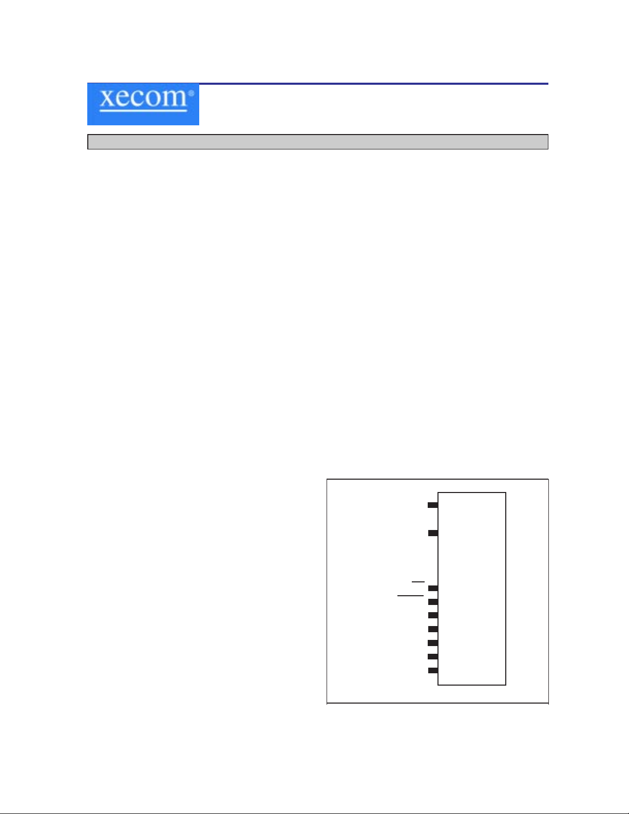
XE10X0 Pin Configuration
1
2
3
4
5
6
7
8
9
Ring
Tip
OH
MUTE
T1
T2
GND
RI
VCC
Page 2
XECOM (2) XE10X0
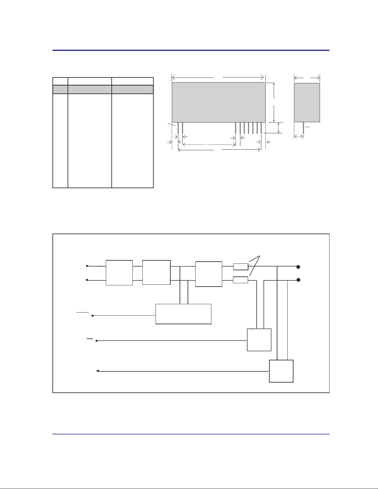
XE10X0 Mechanical Specifications
B
C
D
E
G
H
J
I
A
F
F
Pin 1
Pin 1
Inches Millimeters
Dim Min Max Min Max
A 0.420 0.460 10.80 11.56
B 0.490 0.530 12.45 13.46
C 0.120 0.140 3.05 3.56
D 0.015 0.035 0.38 0.89
E 1.410 1.440 35.81 36.58
F 0.040 0.060 1.02 1.52
G 1.590 1.630 40.39 41.40
H 1.070 1.080 27.18 27.43
I 0.040 0.060 1.02 1.52
J 0.100 0.140 2.54 3.56
K 0.300 0.340 7.62 8.64
Pin Size: 0.018" square
All pins tin-plated.
OH
RI
RING
TIP
HookSwitch
Ring
Detect
T1
T2
MUTE
Over-Current
Protection
(XE1050)
16 KHz
Meter T one
Filter
(XE1040)
Low Impedance
Pulse Dialing
(XE1040, XE1050, XE1070)
Loop Current
Holding
Circuit
Isolation
Transformer
(All)
(All)
(All)
(All)
XE10X0 Block Diagram
Page 3
XECOM (3) XE10X0
Pin Descriptions
PIN NAME DESCRIPTION
1 Ring Ring provides one half of the two-wire connection to the telephone line. Ring
is isolated from all other circuitry. The XE1060 provides a 1500 Volt
isolation barrier; the remaining XE10X0 models provide a 3750 volt isolation
barrier. This isolation must be preserved throughout the system. This
isolation can be maintained by selecting properly rated components and
maintaining sufficient creepage and clearance distances.
2 Tip Tip provides one half of the two-wire connection to the telephone line. Tip is
isolated from all other circuitry. The XE1060 provides a 1500 Volt isolation
barrier; the remaining XE10X0 models provide a 3750 volt isolation barrier.
This isolation must be preserved throughout the system. This isolation can
be maintained by selecting properly rated components and maintaining
sufficient creepage and clearance distances.
3 /OH /OH is an active low input to the XE10X0 DAA module. It controls the internal
hookswitch. A low on OH closes the hookswitch and connects the
equipment to the telephone line.
4 /MUTE This active low input provides low impedance pulse dialing in the XE1040,
XE1050, and XE1070. Presenting a low impedance to the telephone line
during pulse dialing is required in many European countries including
Germany, France and Italy.
5 T1 T1 provides half of the differential input/output connection to the secondary
side of the internal telephone line transformer.
6 T2 T2 provides half of the differential input/output connection to the secondary
side of the internal telephone line transformer.
7 GND This pin provides ground reference for the RI, /OH and /Mute control lines.
There is no connection between ground and the telephone line (primary) side
of the XE10X0 DAA.
8 RI Ring Indicate is an active high output from the DAA module. When a valid
ring signal appears on Tip and Ring, the DAA provides a pulse train at ring
frequency on RI.
9 VCC This pin provides 5 volt DC power for the RI, /OH and /Mute control lines.
There is no connection between VCC and the telephone line (primary) side of
the XE10X0 DAA.
Page 4
XECOM (4) XE10X0
XE1030 Electrical Specifications
(Vcc=+5v ±10%, Ta=0 to 70 deg C)
Power Supply Current Off-Hook 10 15 mA
Transmit Insertion loss 600 Ohm Impedance, 1000 Hz 2 4 dB
Receive Insertion loss 600 Ohm Impedance, 1000 Hz 2 4 dB
Line Impedance At 1000 Hz 540 600 660 Ohms
Coupler Match Input impedance to T1 & T2 430 Ohms
input impedance for 600 ohm line impedance 6.8 nFd
Ring Detect Sensitivity Minimum Ring voltage detected as a 10 20 Vrms
valid ring signal
RI Output Voltage Ring present at Tip & Ring 4.2 Volts
Loop Current Switch OFF: (on-hook) 2.0 3.0 Volts
Control Voltage ON: (off-hook) 0.2 0.5 Volts
OH Control Current Off-Hook 5 mA
Telephone Loop Current Off-Hook 10 120 mA
Parameter Conditions Min Typ Max Units
XE1040 Electrical Specifications
(Vcc=+5v ±10%, Ta=0 to 70 deg C)
Power Supply Current Off-Hook 10 15 mA
Transmit Insertion loss 600 Ohm Impedance, 1000 Hz 2 4 dB
Receive Insertion loss 600 Ohm Impedance, 1000 Hz 2 4 dB
Line Impedance At 1000 Hz Complex
Coupler Match Input impedance to T1 & T2 820 Ohms
input impedance for complex line impedance 82 nFd
Ring Detect Sensitivity Minimum Ring voltage detected as a 20 Vrms
valid ring signal
RI Output Voltage Ring present at Tip & Ring 4.2 Volts
Loop Current Switch OFF: (on-hook) 2.0 3.0 Volts
Control Voltage ON: (off-hook) 0.2 0.5 Volts
OH Control Current Off-Hook 5 mA
Telephone Loop Current Off-Hook 10 60 mA
Parameter Conditions Min Typ Max Units
Page 5
XECOM (5) XE10X0
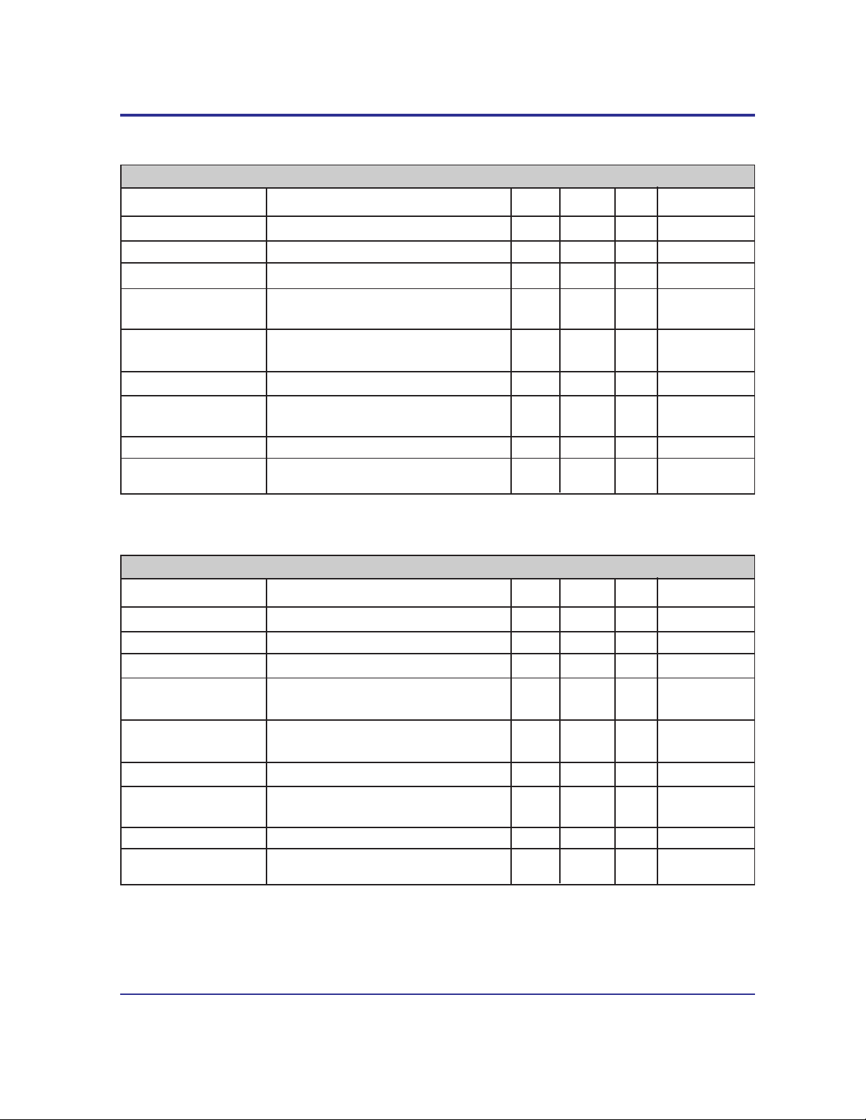
XE1050 Electrical Specifications
(Vcc=+5v ±10%, Ta=0 to 70 deg C)
Power Supply Current Off-Hook 10 15 mA
Transmit Insertion loss 600 Ohm Impedance, 1000 Hz 2 4 dB
Receive Insertion loss 600 Ohm Impedance, 1000 Hz 2 4 dB
Line Impedance At 1000 Hz 540 600 660 ohms
Coupler Match Input impedance to T1 & T2 430 Ohms
input impedance for 600 ohm line impedance 6.8 nFd
Ring Detect Sensitivity Minimum Ring voltage detected as a 20 Vrms
valid ring signal
RI Output Voltage Ring present at Tip & Ring 4.2 Volts
Loop Current Switch OFF: (on-hook) 2.0 3.0 Volts
Control Voltage ON: (off-hook) 0.2 0.5 Volts
OH Control Current Off-Hook 5 mA
Telephone Loop Current Off-Hook 10 45 mA
Parameter Conditions Min Typ Max Units
XE1060 Electrical Specifications
(Vcc=+5v ±10%, Ta=0 to 70 deg C)
Power Supply Current Off-Hook 10 15 mA
Transmit Insertion loss 600 Ohm Impedance, 1000 Hz 2 4 dB
Receive Insertion loss 600 Ohm Impedance, 1000 Hz 2 4 dB
Line Impedance At 1000 Hz 540 600 660 ohms
Coupler Match Input impedance to T1 & T2 340 Ohms
input impedance for 600 ohm line impedance
Ring Detect Sensitivity Minimum Ring voltage detected as a 20 38 Vrms
valid ring signal
RI Output Voltage Ring present at Tip & Ring 4.2 Volts
Loop Current Switch OFF: (on-hook) 2.0 3.0 Volts
Control Voltage ON: (off-hook) 0.2 0.5 Volts
OH Control Current Off-Hook 5 mA
Telephone Loop Current Off-Hook 10 100 mA
Parameter Conditions Min Typ Max Units
Page 6
XECOM (6) XE10X0
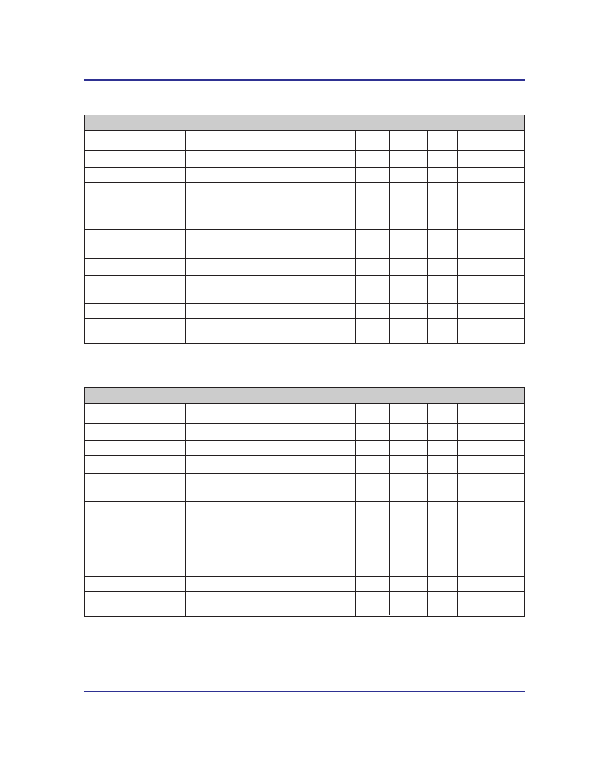
XE1070 Electrical Specifications
(Vcc=+5v ±10%, Ta=0 to 70 deg C)
Power Supply Current Off-Hook 10 15 mA
Transmit Insertion loss 600 Ohm Impedance, 1000 Hz 2 4 dB
Receive Insertion loss 600 Ohm Impedance, 1000 Hz 2 4 dB
Line Impedance At 1000 Hz 540 600 660 ohms
Coupler Match Input impedance to T1 & T2 430 Ohms
input impedance for 600 ohm line impedance 6.8 nFd
Ring Detect Sensitivity Minimum Ring voltage detected as a 15 Vrms
valid ring signal
RI Output Voltage Ring present at Tip & Ring 4.2 Volts
Loop Current Switch OFF: (on-hook) 2.0 3.0 Volts
Control Voltage ON: (off-hook) 0.2 0.5 Volts
OH Control Current Off-Hook 5 mA
Telephone Loop Current Off-Hook 10 120 mA
Parameter Conditions Min Typ Max Units
XE1080 Electrical Specifications
(Vcc=+5v ±10%, Ta=0 to 70 deg C)
Power Supply Current Off-Hook 10 15 mA
Transmit Insertion loss 600 Ohm Impedance, 1000 Hz 2 4 dB
Receive Insertion loss 600 Ohm Impedance, 1000 Hz 2 4 dB
Line Impedance At 1000 Hz 540 600 660 ohms
Coupler Match Input impedance to T1 & T2 430 Ohms
input impedance for 600 ohm line impedance 6.8 nFd
Ring Detect Sensitivity Minimum Ring voltage detected as a 20 Vrms
valid ring signal
RI Output Voltage Ring present at Tip & Ring 4.2 Volts
Loop Current Switch OFF: (on-hook) 2.0 3.0 Volts
Control Voltage ON: (off-hook) 0.2 0.5 Volts
OH Control Current Off-Hook 5 mA
Telephone Loop Current Off-Hook 10 120 mA
Parameter Conditions Min Typ Max Units
Page 7
XECOM (7) XE10X0
ABSOLUTE MAXIMUM RATINGS
Maximum Storage Temperature -25OC to +85OC
Maximum Operating Temperature Range 0OC to +70OC
Maximum Lead Temperature (soldering 2 seconds per wave) 260OC
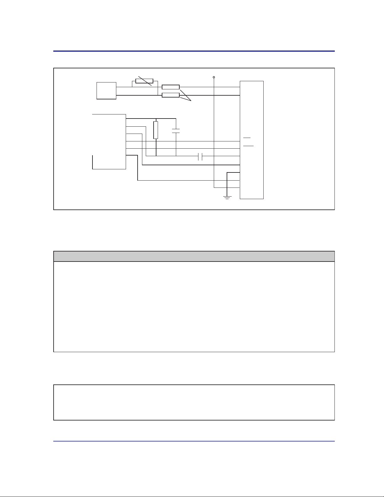
Typical Connection Diagram
1
2
5
6
7
8
RING
TIP
OH
Gnd
VCC
RI
Modem
+5 Volts
3
4
Off hook
Ring Detect
T1
T2
Rm
Telco
9
Mute
Mute
4.7 ufd, 16 Volts
VR1
Cm
TXA
RXA
TXB
15 ohms 1/2 Watt
Rm and CM provide the impedance match with the telephone line. These values are country dependent.
The chart below show the correct Rm and Cm values and correct XE10X0 model for various countries.
VR1 provides protection from voltage surges on the telephone line. The table below show the
recommended breakdown voltage for VR1.
Country Model Rm Value Cm Value VR1 Comments
Canada XE1060 340 ohms - 250 V 600 Ohm Line impedance
France XE1050 430 ohms 6.8 nFd 250 V 600 Ohm Line impedance
Germany XE1040 820 ohms - 250 V Complex Line Impedance
Italy XE1070 430 ohms 6.8 nFd 250 V 600 Ohm Line impedance
Japan XE1060 340 ohms - 250 V 600 Ohm Line impedance
Spain XE1080 430 ohms 6.8 nFd 250 V 600 Ohm Line impedance
United Kingdom (B) XE1030 430 ohms 6.8 nFd 250 V 600 Ohm Line impedance
USA XE1060 340 ohms - 250 V 600 Ohm Line impedance
Page 8

XECOM (8) XE10X0
Copyright, Xecom © 1998
While Xecom, Inc. has made every effort to ensure that the information presented here is accurate, Xecom will not
be liable for any damages arising from errors or omission of fact. Xecom reserves the right to modify specifications
and/or prices without notice. Product mentioned herein are used for identification purposes only and may be
trademarks and/or registered trademarks of their respective companies.
Xecom Incorporated
374 Turquoise Street,Milpitas, CA 95035
Ph:408-945-6640 Fax:408-942-1346
Terms of Sale
Devices sold by XECOM are covered by the warranty provisions appearing in its Terms of Sale only. XECOM
makes no warranty, express, statutory, implied, or by description regarding the information set forth herein, or
regarding the freedom of the described devices from patent infringement. XECOM makes no warranty of
merchantability or fitness for any purposes. XECOM reserves the right to discontinue production and change
specifications and prices at any time and without notice. This product is intended for use in normal commercial
applications. Applications requiring extended temperature range, unusual environmental requirements, or high
reliability applications, such as military, medical life-support or life-sustaining equipment, are specifically not
recommended without additional processing and authorization by XECOM for such application.
Xecom assumes no responsibility for the use of any circuitry other than circuitry embodied in a Xecom product. No
other circuits, patents, or licenses are implied.
Life Support Policy
Xecom's products are not authorized for use as Critical Components in Life Support Devices or Systems.
Life Support Devices or Systems are devices or systems which, (a) are intended for surgical implant into the body,
or (b) support or sustain life, and whose failure to perform, when properly used in accordance with instructions
provided in the labeling, can be reasonably expected to result in significant injury to the user.
A Critical Component is any component of a life support device or system whose failure to perform can be
reasonably expected to cause failure of the life support device or system, or to affect its safety or effectiveness.
 Loading...