

Page 1
XECOM (1) XE056J
XE056J
7/99
Slim-Link R PLCC DAA for 56kBPS Data Transfer
Description
The XE056J is a complete DAA supporting 56 KBPS
data transfer in a compact, surface-mount package. It is
an alternative to discrete DAA’s for high-speed communications. The XE056J replaces 25 to 30 discrete
components with a single, assembled unit. The XE056J
package fits a 68 pin PLCC socket permitting automated,
high-volume assembly .
The XE056J does not sacrifice performance for small
size and surface-mount convenience. The wide bandwidth, low distortion design supports analog data transfer to 56 KBPS.
Like all Xecom DAA's the XE056J is a complete DAA.
It includes the telephone line transformer, loop current
holding circuit, hookswitch and ring indicator. The
XE056J complies with FCC Part 68 rules for direct
connection to the telephone line.
Features
* Modified 68-Pin PLCC package for high-volume
assembly
* Meets line interface requirements for reliable 56
Kbps modems;
* High Performance: Typical Total Harmonic
Distortion -85 dB ;
* FCC Part 68 Compliant;
* Integrated Low-Distortion T elephone Line
Transformer
* Ring Detection, active high and active low options
available;
* Operates on a Single +5 Volt or + 3 Volt Power
Supply;
* Solid-State Hookswitch Control, active high and
active low options available;
* Internal metallic surge protection provided;
* Extended Temperature Ranges available;
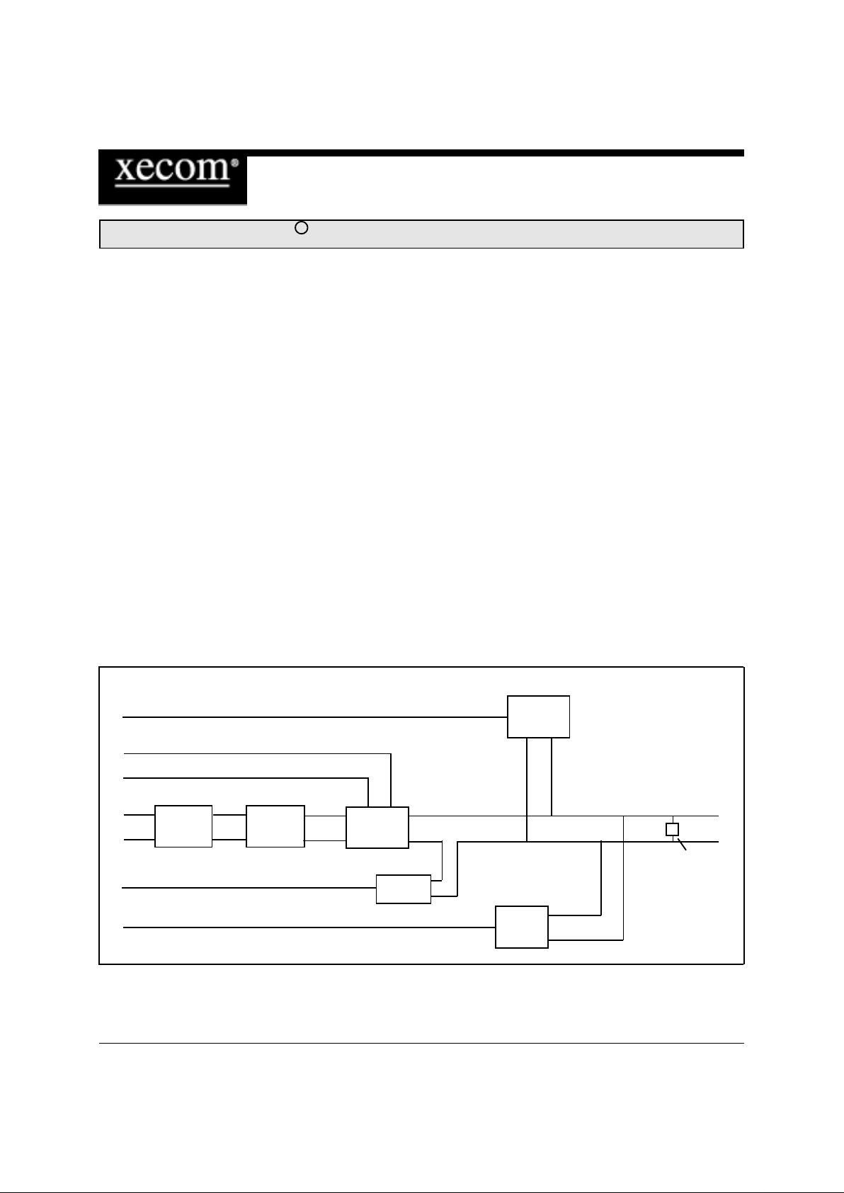
XE056J BLOCK DIAGRAM
Line Trans-
former
Line Current
Holding Cir-
cuit
Hookswitch
Ring De-
tector
T1
T2
OH
RI
Tip
Ring
metallic
surge sup-
pression
Low Imped-
ance Dialing
/MUTE
L1
L2
Billing Tone
Filter
(Optional)
Page 2
XECOM (2) XE056J
XE056J Ordering Information
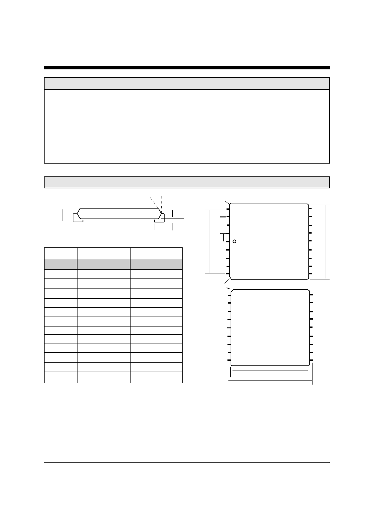
XE056J Mechanical Specifications
h x 45 degrees
(3 Places)
D2
b
e
D1
(top)
10
1
9
Index Corner
J x 45 degrees
D1
(bottom)
A
A1
D3
a
D
A 0.280 0.300 7.11 7.62
A1 0.020 REF 0.508 REF
b 0.017 0.021 0.432 0.533
D 0.985 0.995 25.02 25.27
D1 0.952 REF 24.18 REF
D2 0.800 REF 20.32 REF
D3 0.910 0.930 23.11 23.62
e 0.100 BSC 2.54 BSC
h 0.010 TYP 0.254 TYP
J 0.045 Typ 1.15 TYP
a45
o
TYP 45o TYP
Coplanarity 0.004 Max 0.10 Max
Inches Millimeters
Dim Min Max Min Max
The standard version of the XE056J is the XE056JLHGU. The L indicates that the off-hook control is an active
low; the H indicates that the Ring Indicate output is an active high; the G indicates General Purpose feature set,
and the U indicates the North American country configuration.
There are a number of variations of the XE056J which can be provided on special order. We offer a choice in the
polarity of the Ring Indicate and Off-Hook signals plus variations for many different countries. We also anticipate
adding many new features and options in future versions of this product. Please contact your Xecom sales representative for the correct model number when ordering any of these special versions of the XE056J.
Page 3
XECOM (3) XE056J
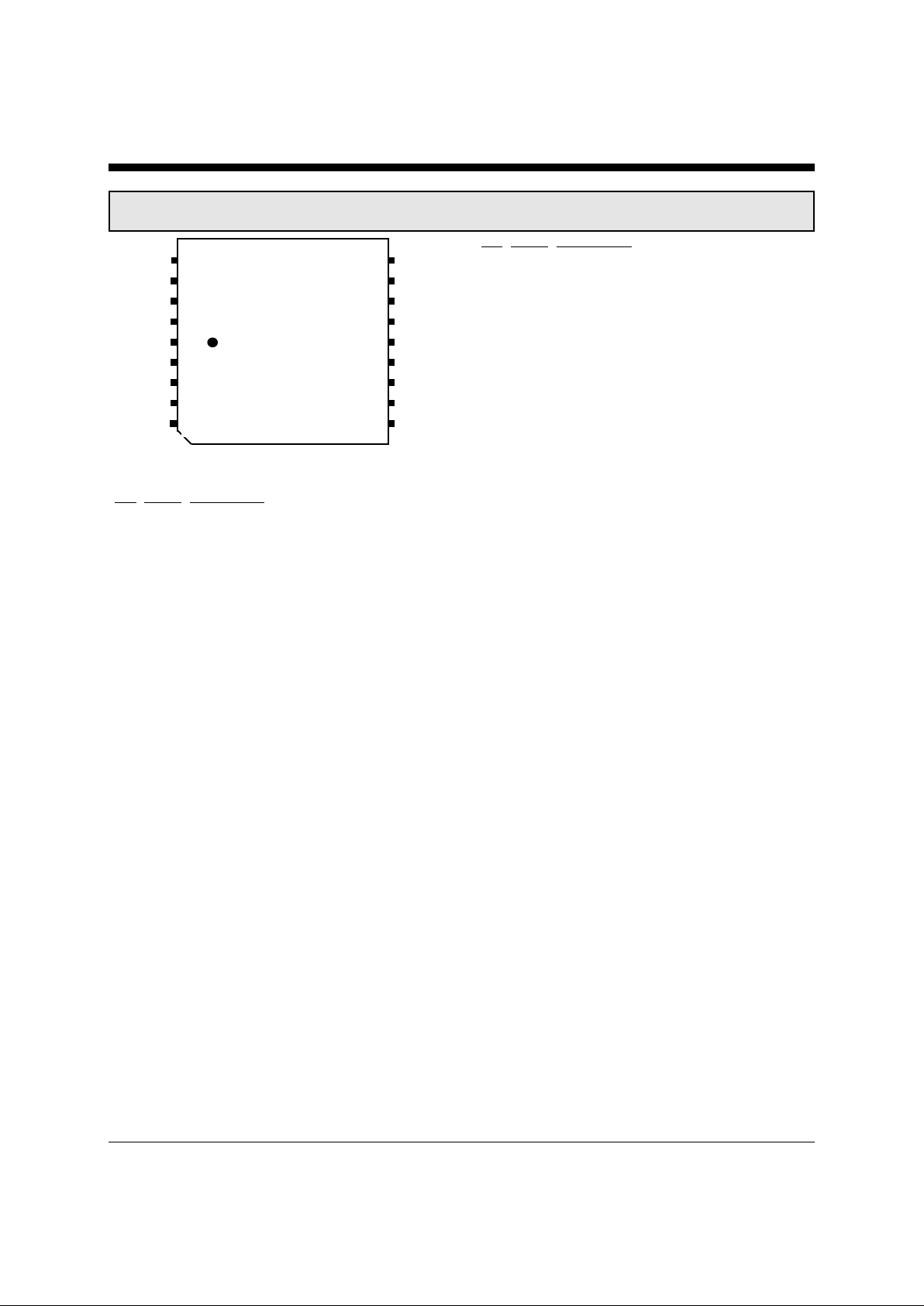
XE056J Pin Descriptions
18
17
16
15
14
13
12
11
10
RI
N/C
N/C
T1
T2
Mute
OH
VCC
Gnd
N/C
Ring
Tip
N/C
L1 (Opt)
L2 (Opt)
N/C
N/C
N/C
XE056J
(top)
1
2
3
4
5
6
7
8
9
Figure 4: XE056J Pin Configuration
Pin Name Description
1 N/C No Connection
2 Ring Ring is one wire of the two-wire telephone line
connection (RJ11 Pin 4). FCC Part 68 Rules
require a 1500 volt isolation barrier between
the telephone line and all other circuits. This
isolation must be preserved throughout the
system. Xecom recommends 0.100 inch
spacing between traces connected to Ring and
all other conductors to preserve this isolation.
3 Tip Tip is one wire of the two-wire telephone line
connection (RJ11 Pin 3). The telephone
company places a DC "Battery" voltage across
Tip and Ring on all public switched telephone
lines. The XE056J accept this line battery
voltage without regard to its polarity.
4 N/C No Connection
5, 6 L2 L1 and L2 provide the points to connect a five
millihenry inductor. This inductor completes
the 16 KHz German billing tone filter.
7-9 N/C No Connection
10 GND Ground connection to the XE056J. This signal
provides the reference for the OH output and RI
input. This pin should be connected to the
systems digital ground.
11 VCC +5 or +3 Volt power source for the XE056J.
VCC powers the RI and OH control lines.
Pin Name Description
12 OH Switch-hook control to the modem. OH is
normally an active low input. OH is available
as an active high input by special order.
Activating OH closes the switch-hook causing
the XE056J to seize the local telephone line.
The telephone line connection is dropped when
OH is deactivated.
The host can pulse OH to simulate rotary
dialing. The pulse rate in the US is ten pulses
per second. Each digit is dialed as a series of
pulses created by closure of the hook-switch.
(one pulse for the digit one to ten pulses for the
digit zero) The pulses must be asymmetrical so
that the hook-switch is closed for thirty-one
milliseconds and open for sixty-nine
milliseconds. An inter-digit delay of at least
one hundred milliseconds is required.
13 Mute Mute is an optional signal on the XE056J.
Countries which require low impedance
dialing, such as Italy, use the Mute signal to
pulse dial.
14 T2 T2 in conjunction with T1 provides the
differential input/output for the analog signal.
T2 connects directly to the secondary side of
the line transformer embedded into the
XE056J. To match the impedance of the DAA
to the 600 ohm telephone line, a 280 ohm
resistor is required on T1 or T2.
15 T1 T1 in conjunction with T2 provides the
differential input/output for the analog signal.
T1 connects directly to the secondary side of
the line transformer embedded into the
XE056J. To match the impedance of the DAA
to the 600 ohm telephone line, a 280 ohm
resistor is required on T1 or T2.
16-17 N/C No Connection
18 RI Ring Indicate output from the modem. RI is
normally active high. RI is available as an active low output by special order. RI provides
a square wave representation of the Ring signal present across Tip and Ring. This permits
intelligent monitoring of the incoming ring.
The XE056J recognizes ring voltages of thirtyeight to one hundred fifty volts RMS in the
frequency range of sixteen to sixty-eight
Hertz.
Page 4
XECOM (4) XE056J
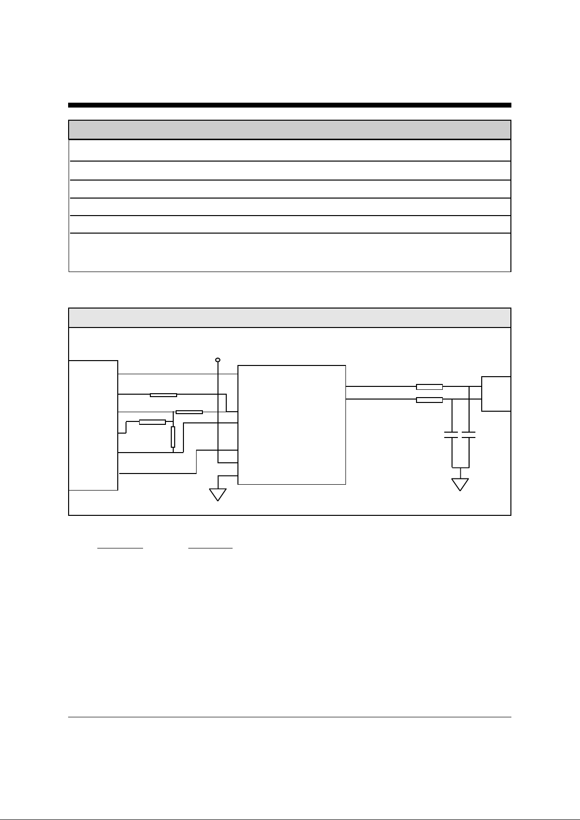
Typical Connections Diagram for North America and Japan
Recommended Parts
Designation Description
C1, C2 47 picofarad, 3000 Volts (Sprague Part Number 30GA-T47)
FB1, FB2 Ferrite Beads (TDK Part Number CB30-453215B)
Conexant
RC336ACF
RINGD
TXA1
RIN
VC
TXA2
-OH
18 RI 1
17 Ring 2
16 Tip 3
15 T1 4
14 T2 L2 5
13 Mute L1 6
12 \OH 7
11 VCC 8
10 GND 9
XECOM
XE056JLHGU
RJ11
280 ohms
2 K
10 K
27 K
FB1
FB2
C1 C2
4
3
+5 Volts
XE056J ABSOLUTE MAXIMUM RATINGS
Storage T emperature -25O C to +85O C
Operating T emperature Range * 0O C to +70O C
Maximum Solder T emperature 220O C
Maximum Time Above Eutectic (183O C) 90 seconds
Preheat Dwell Time 120 to 180 seconds
* The XE56J can be ordered with an Operating T emperature of -40O C to +85O C at extra cost.
Page 5
XECOM (5) XE056J
XE056J Applications Notes
Dialing:
The public switched telephone network permits tone and
rotary (pulse) dialing. The XE056J supports both types. Tone
dialing requires an external signal source to generate the
dialing tones. Rotary dialing is accomplished by pulsing the
OH line on the XE056J.
Pulse Dialing: The XE056J generates dialing pulses through
momentary closures of the switch-hook. (In some countries
pulsing of the MUTE signal is required to meet local pulse
dialing rules.) Each digit is represented as a series of pulses,
one pulse for a one to ten pulses for a zero. The pulse rate
varies from ten pulses per second in North America to 20
pulses per second in Europe. The dialing pulses are asymmetrical. To achieve the correct duty cycle consult with the local
country regulations. An inter-digit delay of at least one
hundred milliseconds separates the digits.
Tone Dialing: To permit tone dialing the XE056J seizes the
line, OH active. For each digit a unique DTMF, Dual Tone
Multiple Frequency, tone pair is placed across T1 and T2. The
higher frequency tone is always larger than the lower frequency one. Transmit the tones for a minimum of 70
milliseconds, and leave a minimum of 70 milliseconds between digits.
The chart below shows the correct DTMF signal frequencies
for each digit.
Digit Lower Tone Upper T one
1 697 1209
2 697 1336
3 697 1477
4 770 1209
5 770 1336
6 770 1477
7 852 1209
8 852 1336
9 852 1477
0 941 1336
* 941 1209
# 941 1477
Signal Levels:
FCC Part 68 Rules set the allowable signal level in the US for
all signals placed on the telephone line other than live voice.
Other countries have similar regulations. Signal levels are
measured in dBm. Zero dBm is 1 milliwatt through a 600
ohm load.
Insertion Loss: There is some loss of signal power as the
information signal passes through the XE056J. This "insertion"
loss should be taken into account when placing signals across
T1 and T2 for transmission. The typical insertion loss of the
XE056J is 6 dB.
Total Harmonic Distortion:
Total harmonic distortion is the most common measure of the
signal path quality provided by the DAA. The primary sources
of this distortion are the telephone line transformer and the line
current holding circuit, although board layout and other factors
can introduce distortion.
Total harmonic distortion varies with frequency. The voice
band provided by the telephone line is limited to under 4000
Hz. High speed modems such as 33.6 KBPS and 56KBPS
require virtually all of this bandwidth for signal transmission.
Even if the total harmonic distortion of a device is very good in
the center portion of the spectrum,signal quality is compromised if distortion greatly increases at the outer limits of the
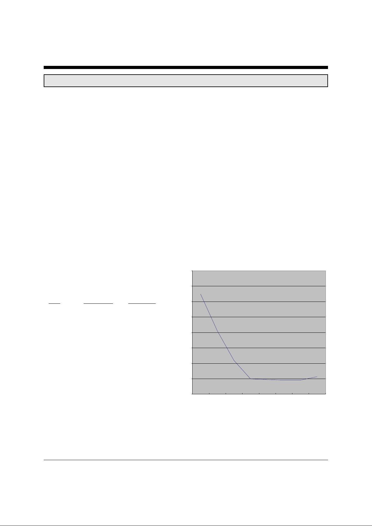
voice band. The figure below shows the typical total harmonic
distortion of the XE056J across the entire voice band.
Total Harmonic Distortion
Total Harmonic Distortion:
Note: This chart represents the total harmonic distortion of the
complete DAA not just the telephone line transformer.
Distortion measurements of the transformer only will
show much lower distortion.
50
55
60
65
70
75
80
85
90
50 100 200 500 1000 1500 2000 4000
Page 6
XECOM (6) XE056J
2/4 Wire Conversion:
Full Duplex communications over a two-wire telephone line requires that transmit and receive signal share the available
bandwidth. The two-to-four wire convertor separates these signals at the host interface. Most modem analog front end chips
incorporate an internal 2/4 wire convertor making it unnecessary to provide one in the DAA.
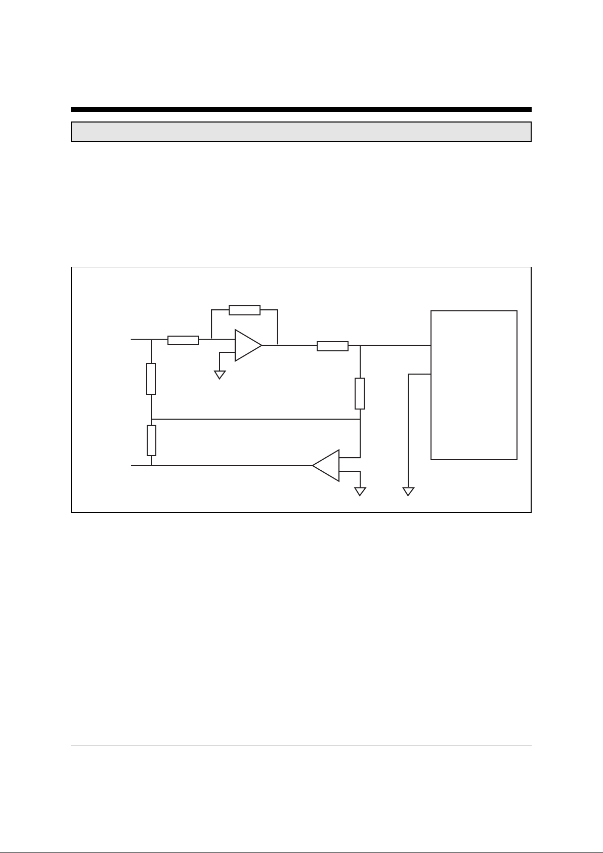
If you are using the XE056J for an application other than a modem, such as voice processing, or your modem analog front end does
not provide the 2/4 wire convertor, you will need to provide a discrete 2/4 wire convertor. Figure 12 shows a simple 2/4 wire
convertor circuit.
XE056J Applications Notes
2/4 Wire convertor
The performance of the 2/4wire convertor is measured by its Transhybrid Loss. The Transhybrid Loss shows how much he 2/4
wire convertor attenuates the transmit signal on the received data line. The circuit above provides a typical Transhybrid Loss of 20
dB.
The Transhybrid Loss will vary with the quality of the impedance match to the telephone line. Even when the recommended value
for the impedance matching resistor, R6, is used variations from line to line alter the impedance match. The value of R3 can be
changed to improve the Transhybrid Loss.
The 2/4 wire convertor also amplifies the transmit and receive signals to compensate for the insertion loss of the DAA. This circuit
provides 6 dB gain of both the transmit and receive signals. The values of R1 and R2 set the transmit gain. The values of R4 and
R5 set the receive gain.
Transmit
Receive
T1
T2
4558
4558
R1
R2
R3
R4
R5
R6
20K
20K
10K
280 ohms
40K
11.5K
XE056J
Page 7
XECOM (7) XE056J
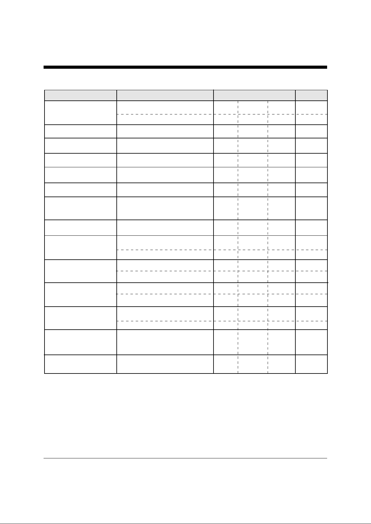
Electrical Specifications (Vcc=+5v ±10%, Ta=0 to 70 deg C)
Power Supply Current Off-hook 10 mA
On-hook 0.5 mA
Transmit Insertion loss 600 Ohm Impedance, 1800 Hz 4.5 6.0 7.0 dB
Receive Insertion loss 600 Ohm Impedance, 1800 Hz 4.5 6.0 7.0 dB
Line Matching Impedance Input to T1 and T2 266 280 294 ohms
Line Impedance see figure 5 540 600 660 ohms
Total Harmonic Distortion 600 Ohm Impedance, 200 to 4000 Hz -80 -85 dB
Ring Detect Sensitivity Min. AC voltage between Tip & 38 150 Vrms
Ring Type B ringer
Ring Frequencies Detected 16 68 Hz
RI Output Voltage Ring signal present, Active low 0 .2 0.5 Volts
Ring signal present, Active High 2.0 5.0 Volts
Hook-Switch Control ON: (off-hook) 0.2 0.5 Volts
Voltage (active low) OFF: (on-hook) 2.0 3.0 Volts
Hook-Switch Control ON: (off-hook) 2.0 3.0 Volts
Voltage (active high) OFF: (on-hook) 0.2 0.5 Volts
Hook-Switch Control ON: (off-hook) 5 10 milliamps
Current OFF: (on-hook) 5 microamps
Loop Current Off-Hook current draw from 20 100 mA
Telephone Line
DC On-Hook Impedance Hookswitch Open 10 MOhms
Parameter Conditions Min Typ Ma x Units
Page 8

XECOM (8) XE056J
XE056J FCC Part 68 Information
When developing a product to be connected to the telephone line, it is necessary to use a circuit known as a Data
Access Arrangement (DAA) approved by the appropriate governmental agency. In the US this agency is the Federal
Communications Commission (FCC), while in Canada it is Industry Canada (IC). These agencies test and approve the
product to ensure that it meets their specifications, thereby protecting the telephone system from damage and
protecting the user from high voltage transients (such as lightning strikes) which may come down the telephone line.
The XE056J has been designed to meet all FCC Part 68 requirements for hazardous voltage, line impedance and
leakage current. If the system transmits data, synthesized voice, or DTMF tones on the telephone line, the user must
certify that the signals transmitted meet basic FCC requirements for maximum transmission levels, out of band energy
and billing delay. Full details may be obtained from the FCC under Part 68 of the FCC Rules and Regulations, or in
Title 47 of the Code of Federal Regulations, however the basic requirements are as follows:
1. Maximum Transmit Level
For the normal “permissive” (standard) telephone line, equipment which transmits data (such as a modem) must not
exceed a transmission level of -9 dBm.
2. Out of Band Energy
Data equipment must not transmit “out of band” energy on the telephone line which exceeds the following limits:
Frequency Range Max. Power
3995 Hz to 4005 Hz -27 dBm
4005 Hz to 12 kHz -20 dBm
12 kHz to 90 kHz -55 dBm
90 kHz to 270 kHz -55 dBm
270 kHz to 6 MHz -15 dBm
3. DTMF Transmission Level
If the system is capable of DTMF dialing, the maximum DTMF transmission level must be less than 0 dBm averaged
over a 3 second interval.
4. Billing Delay
A delay of 2 seconds or greater is required after the time the XE056J is taken “off hook” and before any information
is transmitted. This is required to ensure that billing information may be exchanged between telephone company
central offices without interference.
The user of the XE056J must certify to the FCC that the final system meets the requirements of Part 68 which include
the criteria above as well as the high voltage protection provided by the XE056J. This is generally accomplished
through an independent testing lab which tests the System and submits the proper paperwork to the FCC for approval.
Since the XE056J already complies with FCC Part 68 rules, this is a relatively simple process.
Page 9

XECOM (9) XE056J
Copyright, Xecom © 1999
While Xecom, Inc. has made every effort to ensure that the information presented here is accurate, Xecom will not
be liable for any damages arising from errors or omission of fact. Xecom reserves the right to modify specifications
and/or prices without notice. Product mentioned herein are used for identification purposes only and may be trademarks and/or registered trademarks of their respective companies.
Xecom
Incorporated
374 Turquoise Street, Milpitas, CA 95035
Ph:408-945 -6640 Fax:408 -942-1346
Email: [email protected]
Web Site: http://www.xecom.com
Terms of Sale
Devices sold by XECOM are covered by the warranty provisions appearing in its Terms of Sale only. XECOM
makes no warranty, express, statutory, implied, or by description regarding the information set forth herein, or regarding the freedom of the described devices from patent infringement. XECOM makes no warranty of merchantability or fitness for any purposes. XECOM reserves the right to discontinue production and change specifications
and prices at any time and without notice. This product is intended for use in normal commercial applications.
Applications requiring extended temperature range, unusual environmental requirements, or high reliability applications, such as military, medical life-support or life-sustaining equipment, are specifically not recommended without
additional processing and authorization by XECOM for such application.
Xecom assumes no responsibility for the use of any circuitry other than circuitry embodied in a Xecom product.
No other circuits, patents, or licenses are implied.
Life Support Policy
Xecom's products are not authorized for use as Critical Components in Life Support Devices or Systems.
Life Support Devices or Systems are devices or systems which, (a) are intended for surgical implant into the body,
or (b) support or sustain life, and whose failure to perform, when properly used in accordance with instructions provided in the labeling, can be reasonably expected to result in significant injury to the user.
A Critical Component is any component of a life support device or system whose failure to perform can be reasonably expected to cause failure of the life support device or system, or to affect its safety or effectiveness.
 Loading...