

Page 1
T
V
DATA SHEE
SURFACE-MOUNT CERAMIC
EMI FILTER CAPACITORS
®
X2Y Series
10 V TO 100
Product Specification – Nov. 21, 2006 V.11
Page 2
Phycomp Product specification
Surface-mount ceramic
EMI filter capacitors
X2Y
®
Series
DESCRIPTION
®
X2Y
series is a breakthrough in the design of ceramic multilayer products for decoupling and filtering in an IPD
(integrated passive device).
®
X2Y
products comprise two identical Y-capacitors and one X-capacitor, integrated into a 4 terminal device, which is
available in standard MLCC sizes. Thanks to the unique multilayer construction the device provides noise cancellation
within the device, reducing ESL from nanohenry to picohenry levels.
Using the unique balance between the Y-capacitors and the shielded multilayer structure the X2Y
®
products offer
superior decoupling and filtering.
The X2Y
®
device performs as a broadband filter enabling better EMC compliance for electrical equipment in a wide
range of applications.
FEATURES
• Broadband Filtering and Decoupling: X2Y
®
is
effective up to 10 GHz and frequencies beyond
• Ultra Low ESL: Noise cancellation within X2Y
®
makes ESL reducing from nanohenry to picohenry
levels
• Bypass: Unlike feedthrough capacitors, X2Y
®
is in
bypass, so no DC current limitations
• Matched Y-caps: Two tightly matched line to ground
capacitors in one device
• Superior Balance: Temperature and voltage
variations balanced of two Y-caps
• Aging Reliability: Aging effects are equal on two Y-
caps
BENEFITS
• Fewer Component in Filtering: One X2Y® can
replace multiple inductors and/or capacitors
• Superior Performance in Filtering: One X2Y
®
can
eliminate both differential and common mode noises
• Fewer Component in Decoupling: Up to 1:7
replacement of MLCC in power delivering system
bypass networks
• Superior Performance in Decoupling: Large or
small, X2Y
®
components exhibit ultra low ESL
• Total Cost Savings: Assembly cost savings through
reduced component count and placement costs
• Board Level Design Advantages: Dramatically
reduces via drills, which blocks routing
APPLICATIONS
• EMI filtering on DC motors
SCM049_V
• Filtered connectors (airbag
connectors, RJ-45 connectors)
• High speed data-line filtering
• Decoupling of supply-lines in high
A
G
G
1
2
A
G
2
A
G
G
1
2
speed digital circuits
• Broadband filtering.
• Amplifier decoupling and EMI
suppression.
• IC Decoupling, on-package, on-
B
B
G
Decoupling application EMI filtering application
1
B
PCB.
• DC power line filtering.
• Data line filtering.
• EMI suppression for DC motors.
• Sensors
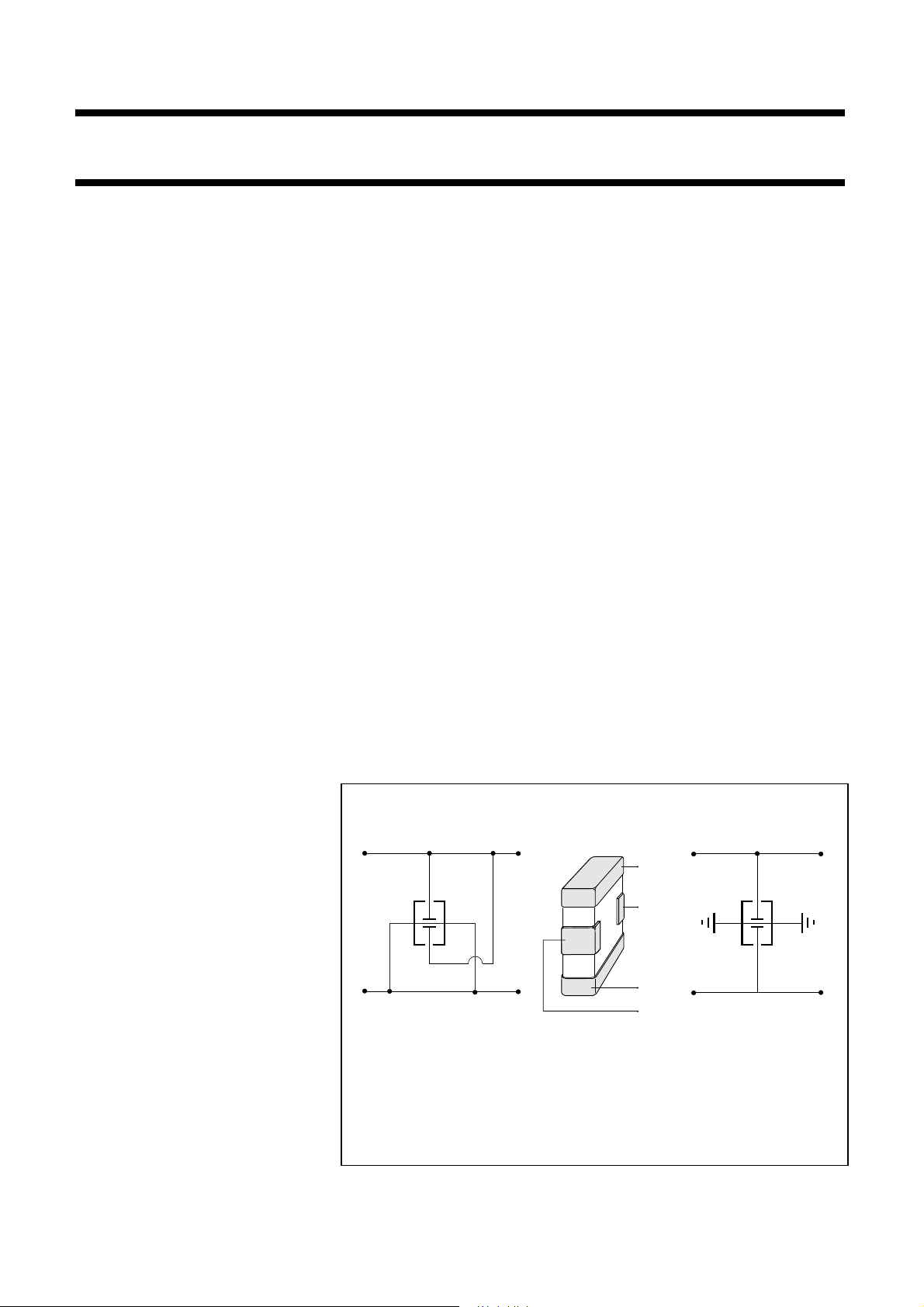
Fig.1 Circuit of typical applications
• Audio
2006 Nov.21 V.11 2 www.yageo.com
Page 3
Phycomp Product specification
Surface-mount ceramic
EMI filter capacitors
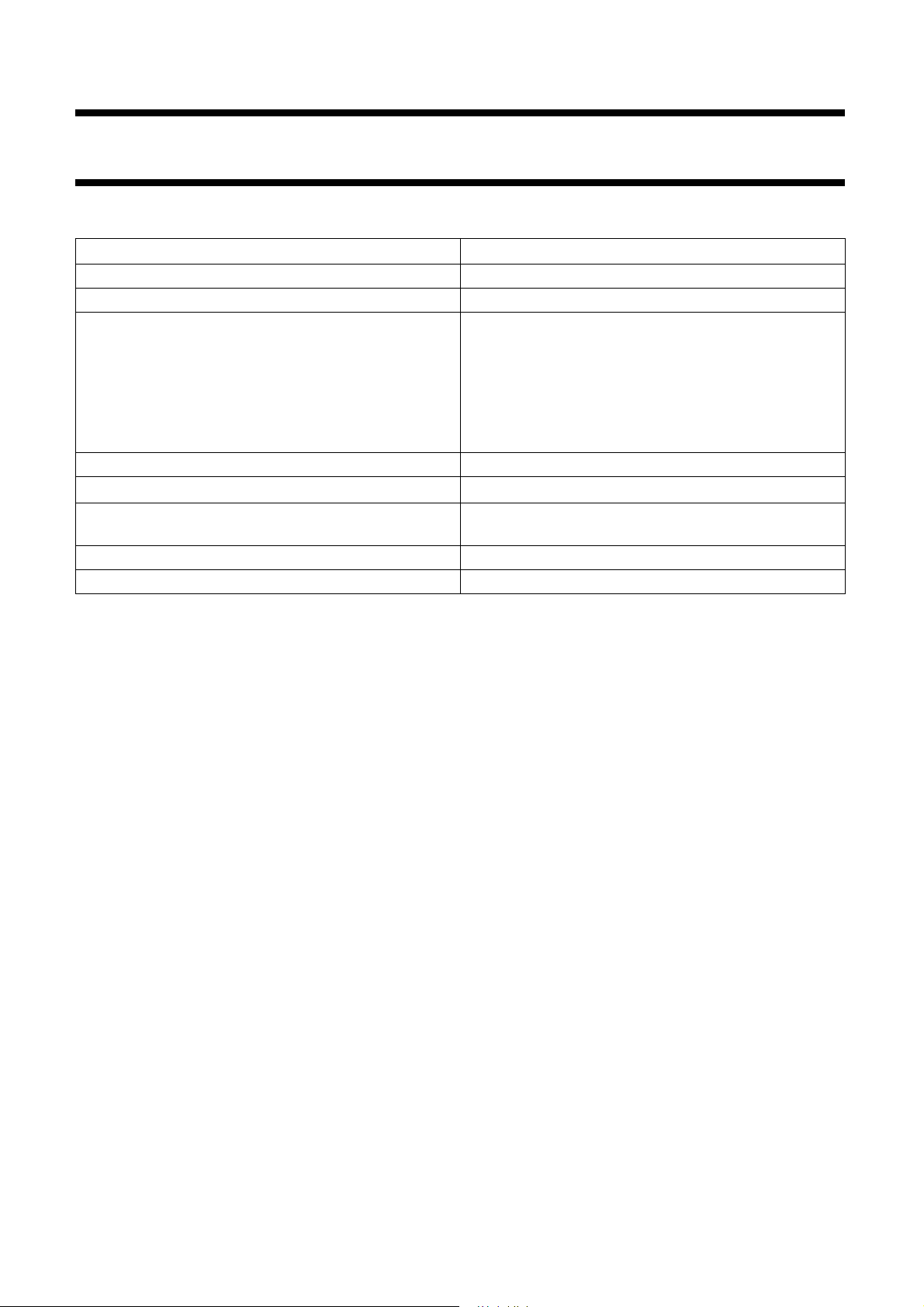
QUICK REFERENCE DATA
DESCRIPTION VALUE
Materials X7R
Rated voltage 10 V, 16 V, 25 V, 50/63 V, 100 V (IEC)
Capacitance range (Y-capacitor):
0603 series 1.5 nF to 100 nF
0805 series 4.7 nF to 180 nF
1206 series 22 nF to 820 nF
1210 series 47 nF to 1 µF
1410 series 390 nF
Tolerance on capacitance ±20%
Test voltage (DC) for 1 minute
Sectional specifications IEC 60384-10, second edition 1989-04; also based on
Detailed specification based on CECC 32 101-801
Climatic category (IEC 60068) X7R: 55/125/56
2.5 × U
CECC 32 100
r
X2Y
®
Series
2006 Nov.21 V.11 3 www.yageo.com
Page 4
Phycomp Product specification
Surface-mount ceramic
EMI filter capacitors
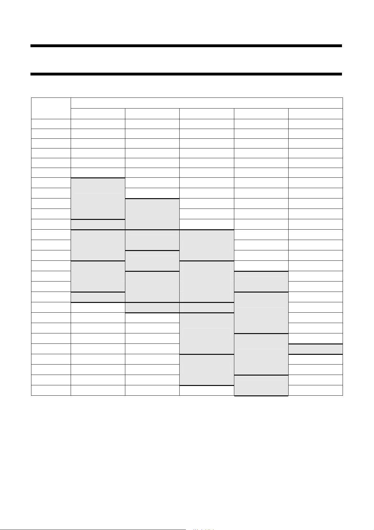
GENERAL SELECTION CHART
C
(pF)
10
22
47
100
220
330
1, 500
2, 200
4, 700
5, 600
10, 000 50 V/63 V
15,000
18 ,000
22 ,000
39 ,000
47 ,000 16 V 50 V/63 V
56 ,000
100, 000 10 V
180, 000 10 V 25 V
220, 000
270, 000
330, 000
390, 000
470, 000
560, 000
820, 000
1 000, 000
0603 0805 1206 1210 1410
100 V
100 V
50 V/63 V
25 V 100 V
25 V
16 V
X7R
100 V
50 V/63 V
16 V
25 V
10 V
16 V
X2Y
®
Series
50 V
2006 Nov.21 V.11 4 www.yageo.com
Page 5
Phycomp Product specification
Surface-mount ceramic
EMI filter capacitors
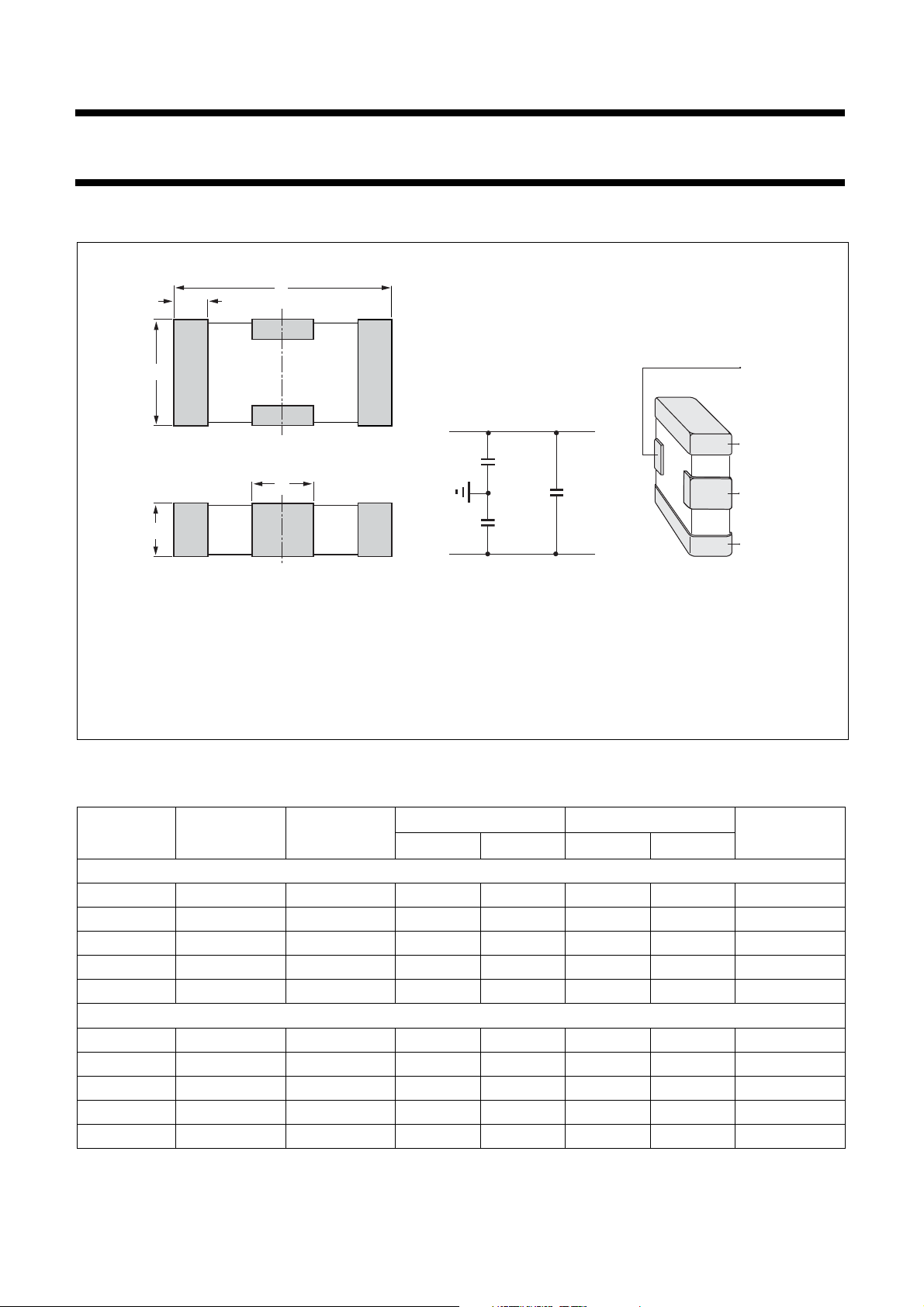
MECHANICAL DATA
A
W
T
L
C
equivalent circuit configuration
line
Cy
Cx
Cy
line
X2Y
SCM051
®
Series
ground
line
ground
line
Simplified typeComponent type
For dimensions see Table 1.
Fig.2. Component outline & simplified outline
Physical dimensions
Table 1 Capacitor dimensions
T A
CASE SIZE L W
MIN. MAX. MIN. MAX.
Dimensions in millimetres
0603 1.6 ±0.15 0.85 ±0.15 0.55 0.75 0.25 0.55 0.40 ±0.20
0805 2.0 ±0.15 1.25 ±0.15 0.75 0.95 0.25 0.55 0.70 ±0.20
1206 3.2 ±0.20 1.65 ±0.20 1.10 1.40 0.25 0.65 1.20 ±0.30
1210 3.2 ±0.20 2.5 ±0.20 1.10 1.70 0.25 0.65 1.20 ±0.30
1410 3.56 ±0.20 2.5 ±0.20 1.10 1.50 0.25 0.65 1.20 ±0.30
Dimensions in inches
0603 0.063 ±0.006 0.032 ±0.006 0.022 0.030 0.010 0.022 0.016 ±0.008
0805 0.079 ±0.006 0.049 ±0.006 0.030 0.037 0.010 0.022 0.028 ±0.008
1206 0.126 ±0.008 0.065 ±0.008 0.043 0.055 0.010 0.026 0.047 ±0.012
1210 0.126 ±0.008 0.098 ±0.008 0.043 0.067 0.010 0.026 0.047 ±0.012
1410 0.140 ±0.008 0.098 ±0.008 0.043 0.059 0.010 0.026 0.047 ±0.012
C
2006 Nov.21 V.11 5 www.yageo.com
Page 6
Phycomp Product specification
Surface-mount ceramic
EMI filter capacitors
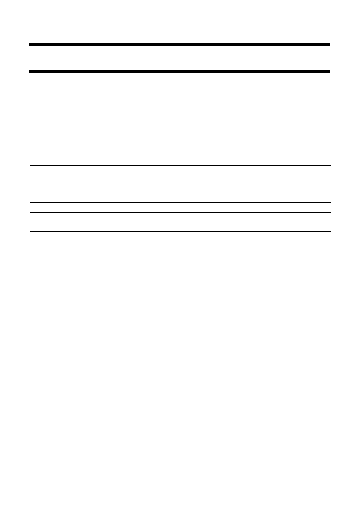
ELECTRICAL CHARACTERISTICS FOR X7R
Class 2 capacitors; X7R dielectric; NiSn terminations
Unless otherwise stated all electrical values apply at an ambient temperature of 20 ±1 °C, an atmospheric pressure of
86 to 106 kPa, and a relative humidity of 63 to 67%.
DESCRIPTION VALUE
Rated voltage Ur (DC)
Capacitance range 1.5 nF to 1 µF
Tolerance on capacitance after 1,000 hours ±20%
Dissipation factor (D.F.); note 1
10 V 5%
16 V 3.5%
≥25 V 2.5%
Insulation resistance after 1 minute at Ur (DC)
Maximum capacitance change as a function of temperature ±15%
Aging Typical 1% per time decade
10 V, 16 V, 25 V, 50 V/63 V and 100 V
R
× C > 500 seconds
ins
X2Y
®
Series
Note
1. Measured at 20 °C, 1 V and 1 MHz, using a four-gauge method.
2006 Nov.21 V.11 6 www.yageo.com
Page 7
Phycomp Product specification
Surface-mount ceramic
EMI filter capacitors
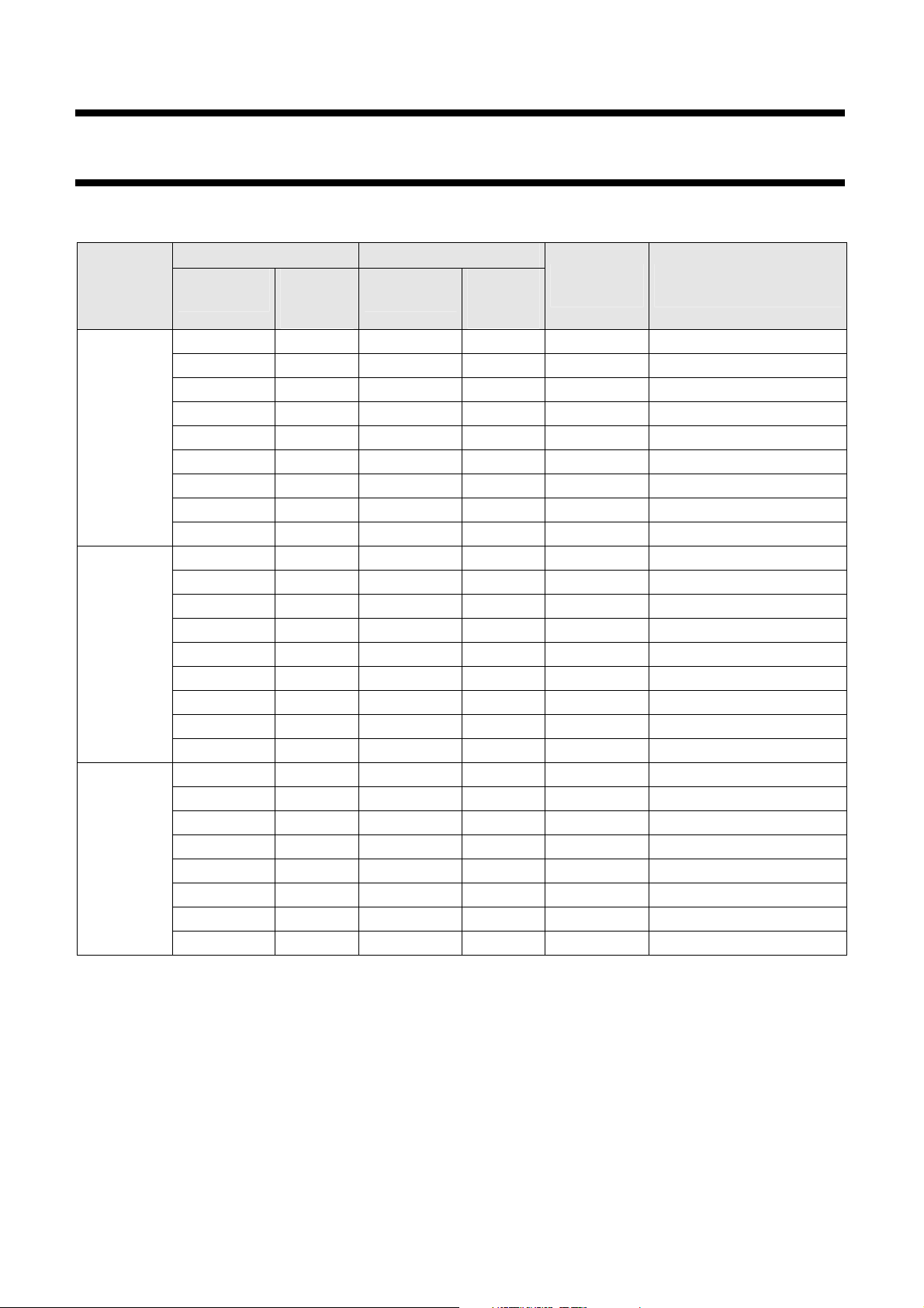
SELECTION CHART FOR X7R SIZES 0603, 0805, 1206
Y-CAPACITOR X-CAPACITOR
SIZE
0603
1206
CAP.
(nF)
1.5 100 0.75 200 0.60 CX 0603 MR X7R 0BB 152
2.2 100 1.1 200 0.60 CX 0603 MR X7R 0BB 222
4.7 100 2.4 200 0.60 CX 0603 MR X7R 0BB 472
5.6 100 2.8 200 0.60 CX 0603 MR X7R 0BB 562
10 50 / 63 5 100 0.60 CX 0603 MR X7R 9BB 103
22 25 11 50 0.60 CX 0603 MR X7R 7BB 223
47 16 24 32 0.60 CX 0603 MR X7R 7BB 473
56 16 28 32 0.60 CX 0603 MR X7R 8BB 563
100 10 50 20 0.60 CX 0603 MR X7R 6BB 104
4.7 100 24 200 0.85 CX 0805 MR X7R 0BB 472 0805
10 100 5 200 0.85 CX 0805 MR X7R 0BB 103
15 50 / 63 8 100 0.85 CX 0805 MR X7R 9BB 153
18 50 / 63 9 100 0.85 CX 0805 MR X7R 9BB 183
22 25 11 50 0.85 CX 0805 MR X7R 8BB 223
39 25 20 50 0.85 CX 0805 MR X7R 8BB 393
47 16 24 32 0.85 CX 0805 MR X7R 7BB 473
100 16 50 32 0.85 CX 0805 MR X7R 7BB 104
180 10 90 20 0.85 CX 0805 MR X7R 7BB 184
22 100 11 200 1.20 CX 1206 MK X7R 0BB 223
47 50 / 63 24 100 1.20 CX 1206 MK X7R 9BB 473
100 50 / 63 50 100 1.20 CX 1206 MK X7R 9BB 104
180 25 90 50 1.20 CX 1206 MK X7R 8BB 184
220 16 110 32 1.20 CX 1206 MK X7R 7BB 224
390 16 195 32 1.20 CX 1206 MK X7R 7BB 394
470 10 235 20 1.20 CX 1206 MK X7R 6BB 474
820 10 410 20 1.20 CX 1206 MK X7R 6BB 824
VOLTAGE
RATING
(V)
CAP.
(nF)
(1)
VOLTAGE
RATING
(V)
THICKNESS
(mm)
®
X2Y
CTC ORDERING CODE
Series
(2) (3)
Notes
1. Other values available on request.
2. Ordering codes for preferred versions (±20% tolerance, 180 mm reel). For other packing and tolerance see
section “Ordering Code Information”.
3. For 12NC ordering codes see Table 2.
2006 Nov.21 V.11 7 www.yageo.com
Page 8
Phycomp Product specification
Surface-mount ceramic
EMI filter capacitors
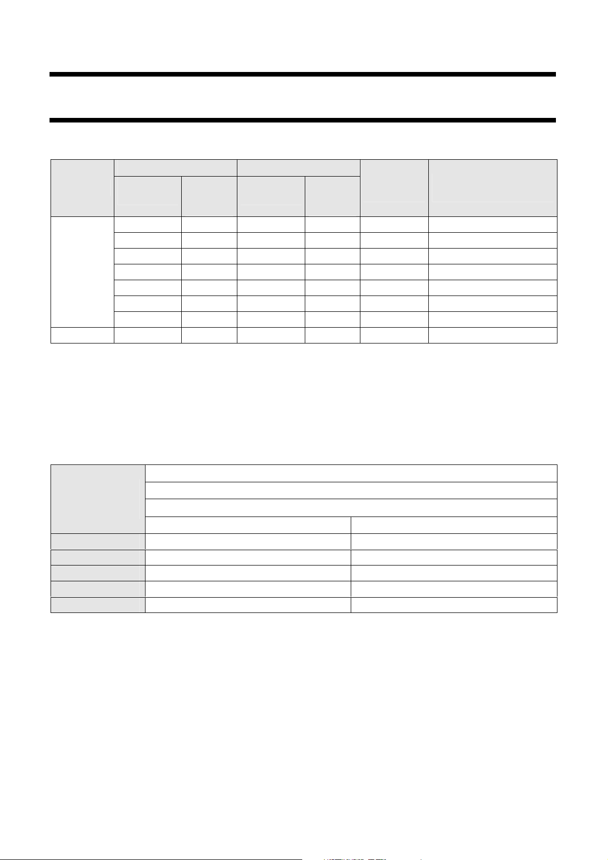
SELECTION CHART FOR X7R SIZES 1210, 1410
Y-CAPACITOR X-CAPACITOR
SIZE
1210
1410 390 50 195 100 1.30 CX 1410 MK X7R 9BB 394
Notes
1. Other values available on request.
CAP.
(nF)
47 100 24 200 1.20 CX 1210 MK X7R 0BB 473
100 50 / 63 50 100 1.20 CX 1210 MK X7R 9BB 104
220 50 / 63 110
470 25 235 50 1.60 CX 1210 MK X7R 8BB 474
560 25 280 50 1.90 CX 1210 MK X7R 8BB 564
820 16 410 32 1.60 CX 1210 MK X7R 7BB 824
1
,000 16 500 32 1.60 CX 1210 MK X7R 7BB 105
VOLTAGE
RATING
(V)
(1)
CAP.
(nF)
VOLTAGE
RATING
(V)
100 1.60 CX 1210 MK X7R 9BB 224
THICKNESS
(mm)
CTC ORDERING CODE
X2Y
(2) (3)
®
Series
2. Ordering codes for preferred versions (±20% tolerance, 180 mm reel). For other packing and tolerance see
section “Ordering Code Information”.
3. For 12NC ordering codes see Table 2.
Thickness classification and packing quantities for X7R
QUANTITY PER REEL
THICKNESS
CLASSIFICATION
(mm)
0.6 ±0.1 4,000
0.85 ±0.1 4,000
1.2 ±0.15
1.6 ±0.15
1.9 ±0.2
PAPER BLISTER
−
−
−
8 mm TAPE WIDTH
∅180 mm; 7"
−
−
2,500
2,500
2,500
2006 Nov.21 V.11 8 www.yageo.com
Page 9
Phycomp Product specification
Surface-mount ceramic
EMI filter capacitors
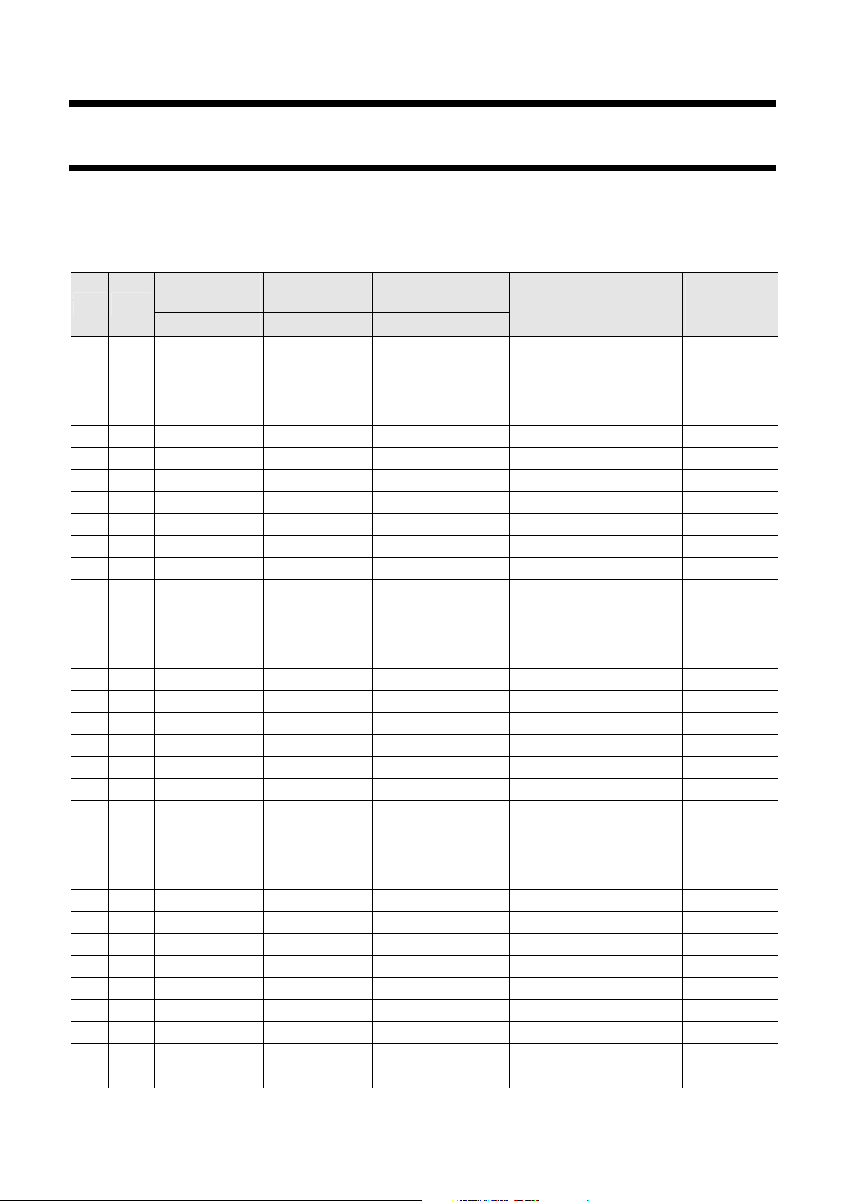
ORDERING INFORMATION
Components may be ordered by using Yageo part number.
Table 2
CAPACITANCE
TC
2006 Nov.21 V.11 9 www.yageo.com
SIZE
X7R 0603 1.5 nF ±20% 100 CX 0603 MR X7R 0BB 152 4,000
X7R 0603 2.2 nF ±20% 100 CX 0603 MR X7R 0BB 222 4,000
X7R 0603 4.7 nF ±20% 100 CX 0603 MR X7R 0BB 472 4,000
X7R 0603 5.6 nF ±20% 100 CX 0603 MR X7R 0BB 562 4,000
X7R 0603 10 nF ±20% 50 / 63 CX 0603 MR X7R 9BB 103 4,000
X7R 0603 22 nF ±20% 25 CX 0603 MR X7R 8BB 223 4,000
X7R 0603 47 nF ±20% 16 CX 0603 MR X7R 7BB 473 4,000
X7R 0603 56 nF ±20% 16 CX 0603 MR X7R 7BB 563 4,000
X7R 0603 100 nF ±20% 10 CX 0603 MR X7R 6BB 104 4,000
X7R 0805 4.7 nF ±20% 100 CX 0805 MR X7R 0BB 472 4,000
X7R 0805 10 nF ±20% 100 CX 0805 MR X7R 0BB 103 4,000
X7R 0805 15 nF ±20% 50 / 63 CX 0805 MR X7R 9BB 153 4,000
X7R 0805 18 nF ±20% 50 / 63 CX 0805 MR X7R 9BB 183 4,000
X7R 0805 22 nF ±20% 25 CX 0805 MR X7R 8BB 223 4,000
X7R 0805 39 nF ±20% 25 CX 0805 MR X7R 8BB 393 4,000
X7R 0805 47 nF ±20% 16 CX 0805 MR X7R 7BB 473 4,000
X7R 0805 100 nF ±20% 16 CX 0805 MR X7R 7BB 104 4,000
X7R 0805 180 nF ±20% 10 CX 0805 MR X7R 6BB 184 4,000
X7R 1206 22 nF ±20% 100 CX 1206 MK X7R 0BB 223 2,500
X7R 1206 47 nF ±20% 50 / 63 CX 1206 MK X7R 9BB 473 2,500
X7R 1206 100 nF ±20% 50 / 63 CX 1206 MK X7R 9BB 104 2,500
X7R 1206 180 nF ±20% 25 CX 1206 MK X7R 8BB 184 2,500
X7R 1206 220 nF ±20% 16 CX 1206 MK X7R 7BB 224 2,500
X7R 1206 390 nF ±20% 16 CX 1206 MK X7R 7BB 394 2,500
X7R 1206 470 nF ±20% 10 CX 1206 MK X7R 6BB 474 2,500
X7R 1206 820 nF ±20% 10 CX 1206 MK X7R 6BB 824 2,500
X7R 1210 47 nF ±20% 100 CX 1210 MK X7R 0BB 473 2,500
X7R 1210 100 nF ±20% 50 / 63 CX 1210 MK X7R 9BB 104 2,500
X7R 1210 220 nF ±20% 50 / 63 CX 1210 MK X7R 9BB 224 2,500
X7R 1210 470 nF ±20% 25 CX 1210 MK X7R 8BB 474 2,500
X7R 1210 560 nF ±20% 25 CX 1210 MK X7R 8BB 564 2,500
X7R 1210 820 nF ±20% 16 CX 1210 MK X7R 7BB 824 2,500
X7R 1210 1 µF ±20% 16 CX 1210 MK X7R 7BB 105 2,500
X7R 1410 390 µF ±20% 50 CX 1410 MK X7R 9BB 394 2,500
VALUE
Y-CAP Y-CAP Y-CAP
CAPACITANCE
TOLERANCE
RATED VOLTAGE
(V)
CTC
ORDERING
CODE
X2Y
®
Series
QUANTITY
PER
REEL
Page 10
Phycomp Product specification
Surface-mount ceramic
EMI filter capacitors
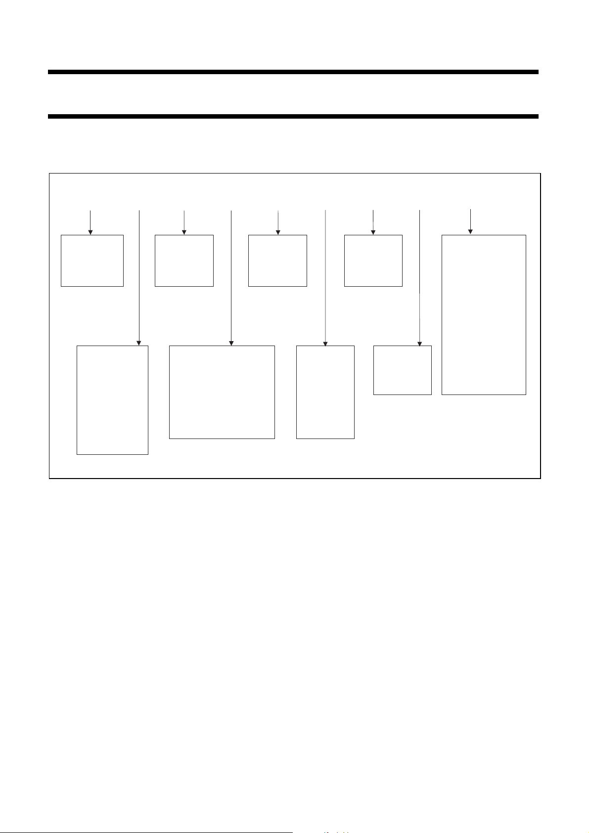
Ordering code: Yageo part number
Example: CX0805MRX7R8BB223
CX
Code 1 - 2
Series name
CX = X2Y® series
Code 3 - 6
Size code
EIA mm
0603 (1608M)
0805 (2012M)
1206 (3216M)
1210 (3225M)
1410 (3625M)
1812 (4632M)
0805 M R
Code 7
Capacitance
tolerance
M = ±20%
Code 8
Packing style
R = Paper tape reel ∅ 7 inch
K = Embossed plastic tape
reel ∅ 7 inch
®
X2Y
Series
X7R
Code 9 - 11 Code 13 Code 15 - 17
TC Material Termination Capacitance value
X7R NP0 B = Ni-Barrier
8
Code 12
Rated voltage
5 = 6.3 V
6 = 10 V
7 = 16 V
8 = 25 V
9 = 50 V
0 = 100 V
BB
(2 significant digits +
number of zeros; the
third digit signifies the
multiplying factor, and
letter R is decimal point)
0 = x 1
1 = x 10
2 = x 10
Code 14
Process code
B = X7R
3 = x 10
4 = x 10
5 = x 10
6 = x 10
223
2
3
4
5
6
SCM045
2006 Nov.21 V.11 10 www.yageo.com
Page 11
Phycomp Product specification
Surface-mount ceramic
EMI filter capacitors
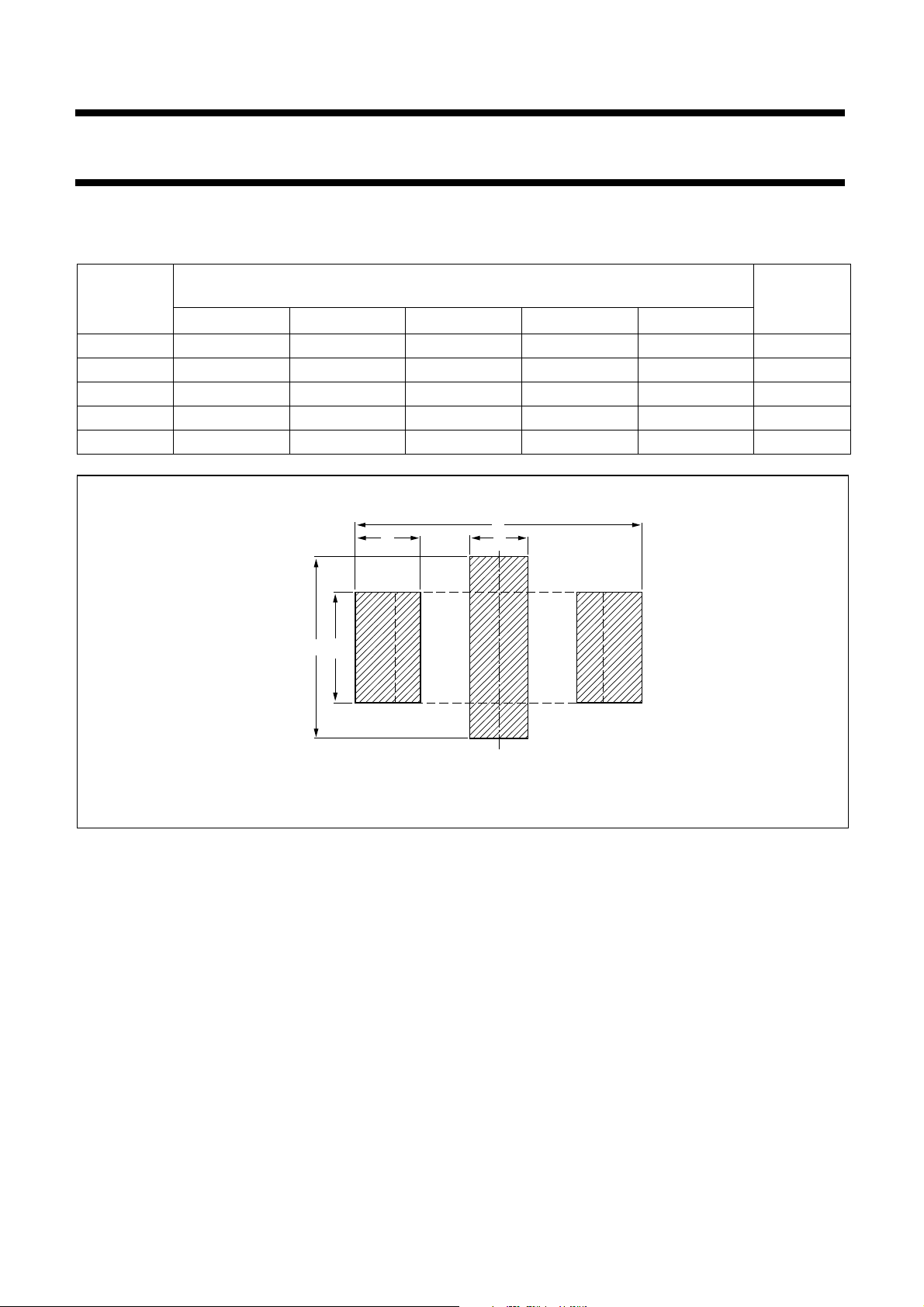
RECOMMENDED DIMENSIONS OF SOLDER LANDS
Table 3 Reflow soldering
CASE SIZE
(EIA)
A B C D E
0603 2.30 0.76 0.64 0.51 1.52 ±0.20
0805 3.05 1.27 0.89 0.56 2.03 ±0.20
1206 4.06 1.65 1.00 1.02 3.05 ±0.25
1210 4.57 2.55 1.00 1.14 4.06 ±0.25
1410 4.57 2.55 1.00 1.14 4.06 ±0.25
Footprint dimensions
(mm)
A
DC
X2Y
®
Series
Placement
Accuracy
(mm)
B
E
HBK085
Fig.3 Recommended dimensions of solder lands
2006 Nov.21 V.11 11 www.yageo.com
Page 12
Phycomp Product specification
Surface-mount ceramic
EMI filter capacitors
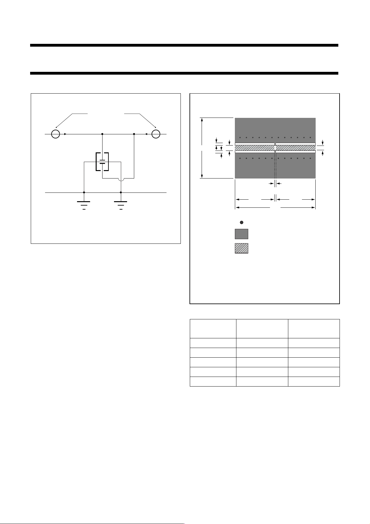
MEASUREMENT SETUP
network analyzer
A
G
Fig.4 X2Y
®
series through measurement
G
1
2
B
SCM046
19.2
0.8
0.8
1.6
X2Y
A
12.55 12.55
25.6
Via
Ground plane
®
Series
SCM048
B
• X2Y
®
are soldered on a printed circuit board
• PCB: FR-4 substrate, with 50 Ω microstrip line
• Network Analyzer: Agilent E5071b
• Calibration: full 2-port calibration with 85033E kit
50 Ω microstrip line
with CPW design method
Size 0603: A=0.5 mm, B=1.2 mm
For other dimensions see Table 4
Fig.5 Testing board for measurement
Table 4 Recommended dimensions of measurement
CASE SIZE A (mm) B (mm)
0603 0.5 ±0.10 1.2 ±0.10
0805 0.8 ±0.10 1.6 ±0.10
1206 1.2 ±0.10 2.8 ±0.15
1210 2.1 ±0.15 2.8 ±0.15
1410 2.1 ±0.15 3.1 ±0.15
2006 Nov.21 V.11 12 www.yageo.com
Page 13
Phycomp Product specification
Surface-mount ceramic
EMI filter capacitors
TESTS AND REQUIREMENTS
Table 5 Test procedures and requirements
TEST METHOD
IEC60384-21/22
4.3 mounting The capacitors may be mounted on printed-
4.4 visual inspection
4.5.1 capacitance NP0:
4.5.2 Dissipation factor
4.5.3 insulation
4.5.4.2 voltage proof Test voltage (DC) applied for 1 minute
TEST PROCEDURE REQUIREMENTS
circuit boards or ceramic substrates
any applicable method using ×10
and dimension
magnification
check
f = 1 MHz for C ≤ 1 nF, measuring at
voltage 1 V
at 20 °C;
rms
f = 1 KHz for C > 1 nF, measuring at voltage
1 V
at 20 °C
rms
X5R/X7R/Y5V:
f = 1 KHz for C ≤ 10 µF, measuring at
voltage 1 V
at 20 °C
rms
NP0:
(D.F.)
f = 1 MHz for C ≤ 1 nF, measuring at
voltage 1 V
at 20 °C;
rms
f = 1 KHz for C > 1 nF, measuring at voltage
1 V
at 20 °C
rms
X5R/X7R/Y5V:
f = 1 KHz for C ≤ 10 µF, measuring at
voltage 1 V
at 20 °C
rms
(DC) for 1 minute
at U
r
resistance
U
≤ 100 V: 2.5 × Ur applied to
r
NP0/X5R/X7R/Y5V series
100 V < U
≤ 200 V: 1.5 × Ur + 100 V
r
applied to NP0/X7R series
200 V < Ur ≤ 500 V: 1.3 × Ur + 100 V
applied to NP0/X7R series
Ur > 500 V: 1.3 × Ur applied to NP0/X7R
series
I: 7.5 mA
®
X2Y
Series
no visible damage
in accordance with
specification
within specified tolerance
in accordance with
specifications
in accordance with
specification
no breakdown or flashover
2006 Nov.21 V.11 13 www.yageo.com
Page 14

Phycomp Product specification
Surface-mount ceramic
EMI filter capacitors
Table 5 Test procedures and requirements (continued)
TEST METHOD
IEC 60384-21/22
4.6 temperature
4.15 adhesion A force applied for 10 seconds to the line
4.9 Resistance to
4.10 Solderability Unmounted chips completely immersed in
TEST PROCEDURE REQUIREMENTS
Between minimum and maximum
characteristic
of plating on
end face
soldering heat
temperature
joining the terminations and in a plane
parallel to the substrate
for size ≥ 0603: a force of 5 N applied
for size 0402: a force of 2.5 N applied
for size 0201: a force of 1 N applied
Mounting in accordance with IEC 60384-22
paragraph 4.3
Conditions: bending 1 mm at a rate of 1
mm/s, radius jig 340 mm
Precondition: 150 +0/−10 °C for 1 hour,
then keep for 24 ±1 hours at room
temperature
Preheating: for size ≤ 1206: 120 to 150 °C
for 1 minute
Preheating: for size >1206: 100 to 120 °C
for 1 minute and 170 to 200 °C for 1 minute
Solder bath temperature: 260 ±5 °C
Dipping time: 10 ±0.5 seconds
Recovery time: 24 ±2 hours
a solder bath at 235 ±5 °C
Dipping time: 2 ±0.5 seconds
Depth of immersion: 10 mm
®
X2Y
NP0: ∆C/C: ±30 ppm/°C
X5R/X7R: ∆C/C: ±15%
Y5V: ∆C/C: +22% ~ −82%
no visible damage
no visible damage 4.8 bond strength
NP0: l∆C/Cl: ≤ 1% or 0.5 pF
whichever is greater
X5R/X7R/Y5V: l∆C/Cl: ≤ 10%
The termination shall be well
tinned
NP0: l∆C/Cl: ≤ 0.5% or 0.5
pF whichever is greater
X5R/X7R: l∆C/Cl: ≤ 10%
Y5V: l∆C/Cl: ≤ 20%
D.F.: within initial specified
value
: within initial specified
R
ins
value
The termination shall be well
tinned
Series
2006 Nov.21 V.11 14 www.yageo.com
Page 15
Phycomp Product specification
Surface-mount ceramic
EMI filter capacitors
Table 5 Test procedures and requirements (continued)
TEST METHOD
IEC 60384-21/22
4.11 Rapid change
4.13 Damp heat,
4.14 Endurance Preconditioning;
TEST PROCEDURE REQUIREMENTS
Preconditioning;
of temperature
150 +0/−10 °C for 1 hour, then keep for 24
±1 hours at room temperature
5 cycles with following detail:
30 minutes at lower category temperature;
30 minutes at upper category temperature
Recovery time 24 ±2 hours
Initial measurements; after 150 +0/−10 °C for
load
with U
r
1 hour, then keep for 24 ±1 hours at room
temperature
Duration and conditions: 500 ±12 hours at
40 ±2 °C; 90 to 95% RH; U
applied
r
Final measurement: perform a heat
treatment at 150 +0/−10 °C for 1 hour, final
measurements shall be carried out 24 ±1
hours after recovery at room temperature
without load
Initial measurements; after 150 +0/−10 °C for
1 hour, then keep for 24 ±1 hours at room
temperature
Duration and conditions: 1,000 ±12 hours at
upper category temperature with 1.5 × U
voltage applied
Final measurement: perform a heat
treatment at 150 +0/−10 °C for 1 hour, final
measurements shall be carried out 24 ±1
hours after recovery at room temperature
without load
®
X2Y
Series
No visual damage
NP0: l∆C/Cl: ≤ 1% or 1 pF
whichever is greater
X5R/X7R: l∆C/Cl: ≤ 15%
Y5V: l∆C/Cl: ≤ 20%
D.F.: within initial specified
value
: within initial specified
R
ins
value
NP0: l∆C/Cl: ≤ 2% or 1 pF
whichever is greater
X5R/X7R: l∆C/Cl: ≤ 20%
Y5V: l∆C/Cl: ≤ 30%
NP0/X5R/X7R/Y5V: D.F.: 2
× initial value max.
NP0: R
R
ins
≥ 2,500 MΩ or
ins
× Cr ≥ 25 seconds,
whichever is less
X5R/X7R/Y5V: R
MΩ or R
× Cr ≥ 25
ins
≥ 500
ins
seconds, whichever is less
NP0: l∆C/Cl: ≤ 2% or 1 pF
whichever is greater
X5R/X7R: l∆C/Cl: ≤ 20%
Y5V: l∆C/Cl: ≤ 30%
r
NP0/X5R/X7R/Y5V: D.F.: 2
× initial value max.
NP0: R
R
ins
≥ 4,000 MΩ or
ins
× Cr ≥ 40 seconds,
whichever is less
X5R/X7R/Y5V: R
MΩ or R
× Cr ≥ 50
ins
≥ 1,000
ins
seconds, whichever is less
2006 Nov.21 V.11 15 www.yageo.com
Page 16

Phycomp Product specification
Surface-mount ceramic
EMI filter capacitors
REVISION HISTORY
Revision Date Change
Notification
Rev.5 2001 Sep 25 - - Published on web
Rev.6 2002 Jul 10 - - Product range extended in all materials and sizes;
Rev.7 2003 Apr 02 - - Updated company logo
Rev.8 2003 Jul 23 - - Cover page revised
Rev.9 2003 Sep 09 - - Cover page corrected
Rev.10 2004 Apr 21 - - Product range updated
Rev.11 2006 Nov 21 - - Size 1410 extended
Description
- Insertion loss measurements added.
- NP0, Y5V and size 1812 removed.
- Product applications, features and benefits update
- Measurement setup added
- Updated tests and requirements
X2Y
®
Series
2006 Nov.21 V.11 16 www.yageo.com
 Loading...