

Page 1
WTL2622
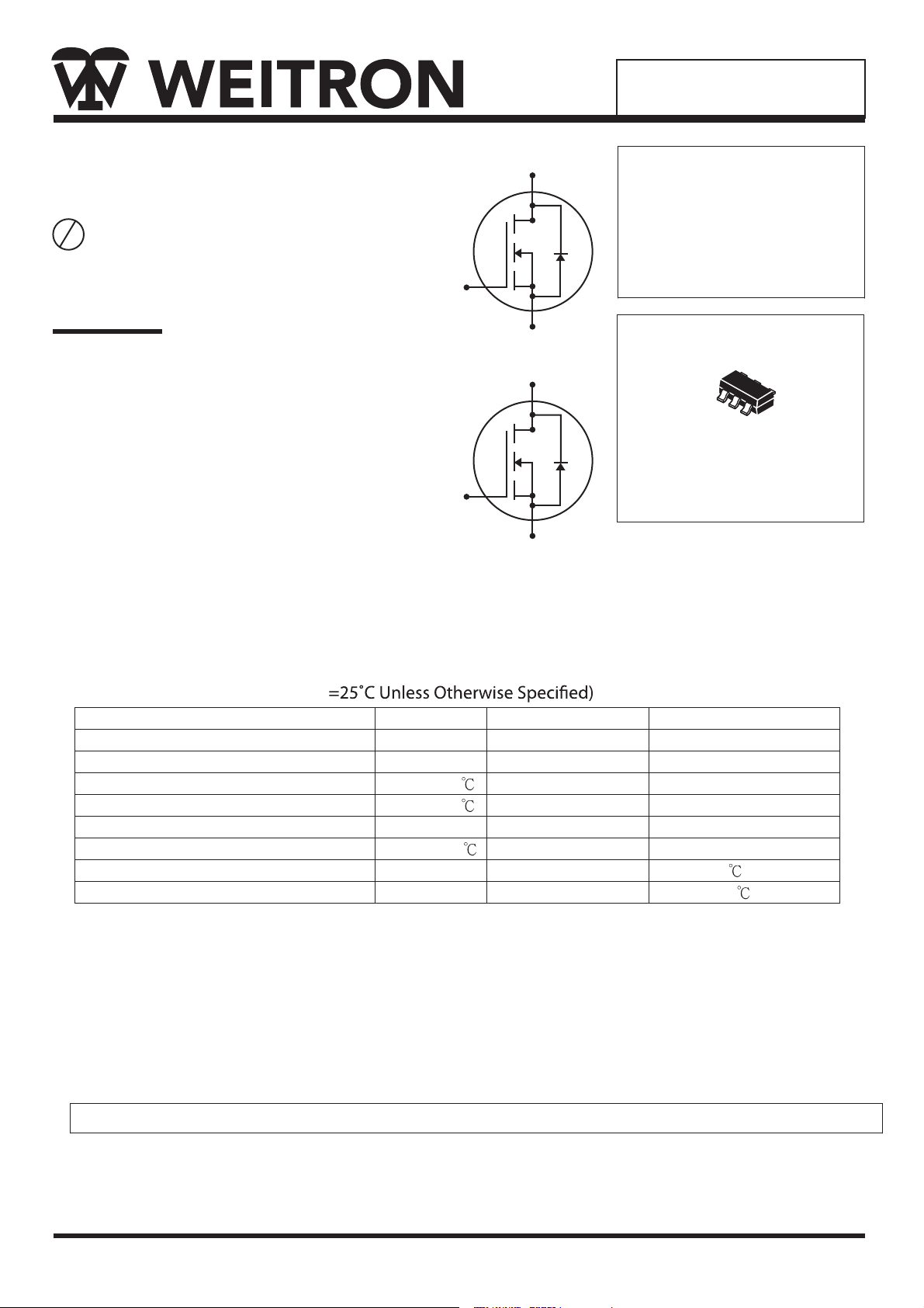
Dual N-Channel Enhancement
Mode MOSFET
P b
Lead(Pb)-Free
Features:
* Low Gate charge
* Surface Mount Package
1 GATE
3 GATE
6 DRAIN
5 SOURCE
4 DRAIN
2 SOURCE
DRAIN CURRENT
520mAMPERES
DRAIN SOURCE VOLTAGE
50 VOLTAGE
6
5
4
1
2
3
SOT-26
Maximum Ratings (T
Parameter Symbol Ratings Uni t
Drain-Source Voltage V
Gate-Source Voltage V
Continuous Drain Current3, VGS@10V ID@TA=25 520 mA
Continuous Drain Current3, VGS@10V ID@TA=70 410 mA
Pulsed Drain Current
Total Power Dissipation PD@TA=25 0.8 W
Thermal Resistance Junction-ambient
Operating Junction and Storage Temperature Range
1
A
50 V
±20 V
1.5 A
3
Max.
DS
GS
I
DM
Rthj-a 150
Tj, Tstg -55 ~ +150
Device Marking
WTL2622=2622
/W
WEITRON
http:www.weitron.com.tw
1/5
19-Sep-05
Page 2
WTL2622
Ele ctrical Characteristics (Tj = 25 unless otherwise specified)
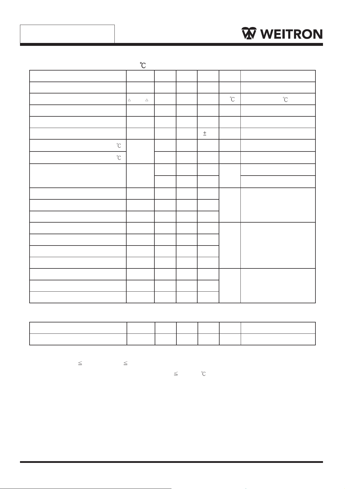
Parameter Symb ol Min. Typ. Max. Unit Test Conditions
Drain-Source Breakdown Voltage
Breakdown Voltage Temperature Coefficient
Gate Threshold Voltage
Forward Transconductance
Gate-Source Leakage Current
Drain-Source Leakage Current(Tj=25 )
Drain-Source Leakage Current(Tj=70 )
Static Drain-Source On-Resistance
Total Gate Charge
2
Gate-Source Charge
Gate-Drain (“Miller”) Change
Turn-on Delay Time
2
Rise Time
Turn-off Delay Time
Fall Time
BV
BV
DSS
V
GS(th)
g
I
GSS
I
DSS
R
DS(ON)
Q
Q
Q
T
d(on)
T
d(off)
DSS
fs
gs
gd
T
T
50 - - V
/
Tj
- 0.06 - V/
1.0 - 3.0 V
- 600 - mS
- -
- - 10 uA
- - 100 uA
- - 1.8
30
VGS=0, ID=250uA
Reference to 25 , ID=1mA
VDS=VGS, ID=250uA
V
=10V, ID=500mA
DS
uA
VGS= ±20V
VDS=50V, VGS=0
VDS=40V, VGS=0
VGS=10V, ID=500mA
fl
- - 3.2
g
- 1 1.6
- 0.5 -
- 0.5 -
- 12 -
r
- 10 -
- 56 -
f
- 29 -
VGS=4.5V, ID=200mA
ID=500mA
nC
VDS=40V
VGS=4.5V
VDS=25V
ID=500mA
ns
VGS=10V
RG=3.3fl
RD=50fl
Input Capacitance
Output Capacitance
Reverse Transfer Capacitance
C
iss
C
oss
C
rss
- 32 50
- 8 -
- 6 -
pF
VGS=0V
VDS=25V
f=1.0MHz
Source-Drain Diode
Parameter Symbol Min. Typ. Max. Unit Test Conditions
Forward On Voltage
Notes: 1. Pulse width l imited by Max. junction temperature.
2. Pulse width 300us, duty cycle 2%.
3. Surface mounted on 1 in2copper pad of FR4 board, t 5sec; 250 /W when mounted on Min. copper pad.
2
V
SD
- - 1.3 V
IS=600mA, VGS=0V
WEITRON
http:www.weitron.com.tw
2/5 19-Sep-05
Page 3
WTL2622
WEITRON
http://www.weitron.com.tw
3/5 19-Sep-05
Page 4
WTL2622
WEITRON
http://www.weitron.com.tw
4/5 19-Sep-05
Page 5
WTL2622
19-Sep-05
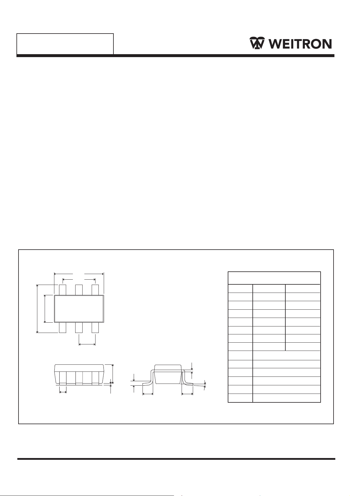
SOT-26 Outline Dimension
A
G
B
C
Top View
Front View
D
L
H
E
F1
J
Side View
Unit:mm
SOT-26
Dim
A
B
C
D
E
F
F1
G
I
F
K
H
I
J
K
L
Min Max
2.70 3.10
2.60
1.40 1.80
0.30 0.55
0.00
0˚ 10˚
0.08
1.90 REF
1.20 REF
0.12 REF
0.37 REF
0.60 REF
0.95 REF
3.00
0.10
0.25
http://www.weitron.com.tw
WEITRON
5/5
 Loading...