

Page 1

WT8048
eltrend
DESCRIPTION
The WT8048 is a 8 pin P-DIP package IC, designed for the application of Power Saving
Monitor or Green Monitor.
As per DPMS proposal, the WT8048 provides a detective circuit of monitor power
management for the convenience of designers in designing Power Saving Monitor.
FEATURES
{ Accepting two seperated H&V synchronous signals with positive/ negative polarity.
DPMS (Display Power Management
Signaling) Detector for Green Monitor
Aug. 31, 1995
{ Capable of processing horizontal frequency between 0Hz to 100kHz, and vertical
frequency between 0Hz to 100Hz.
{ Power Saving mode - It can detect the conditions of monitor to decide which will be
selected as following: ON mode / STAND_BY mode / SUSPEND mode / OFF mode.
{ An Override mode is defined to override the DPMS function during the design, test,
burn-in manufacture or diagnostic process if desired.
APPLICATION
{ DPMS mode's detection for Green Monitor
Weltrend Semiconductor, Inc. 2F., No. 24, Ind. E. 9th Rd., Science-Based Ind. Park,
Hsin-Chu, Taiwan, R. O. C.
Tel: 886-35-780241 Fax: 886-35-7704191
Page 2
eltrend
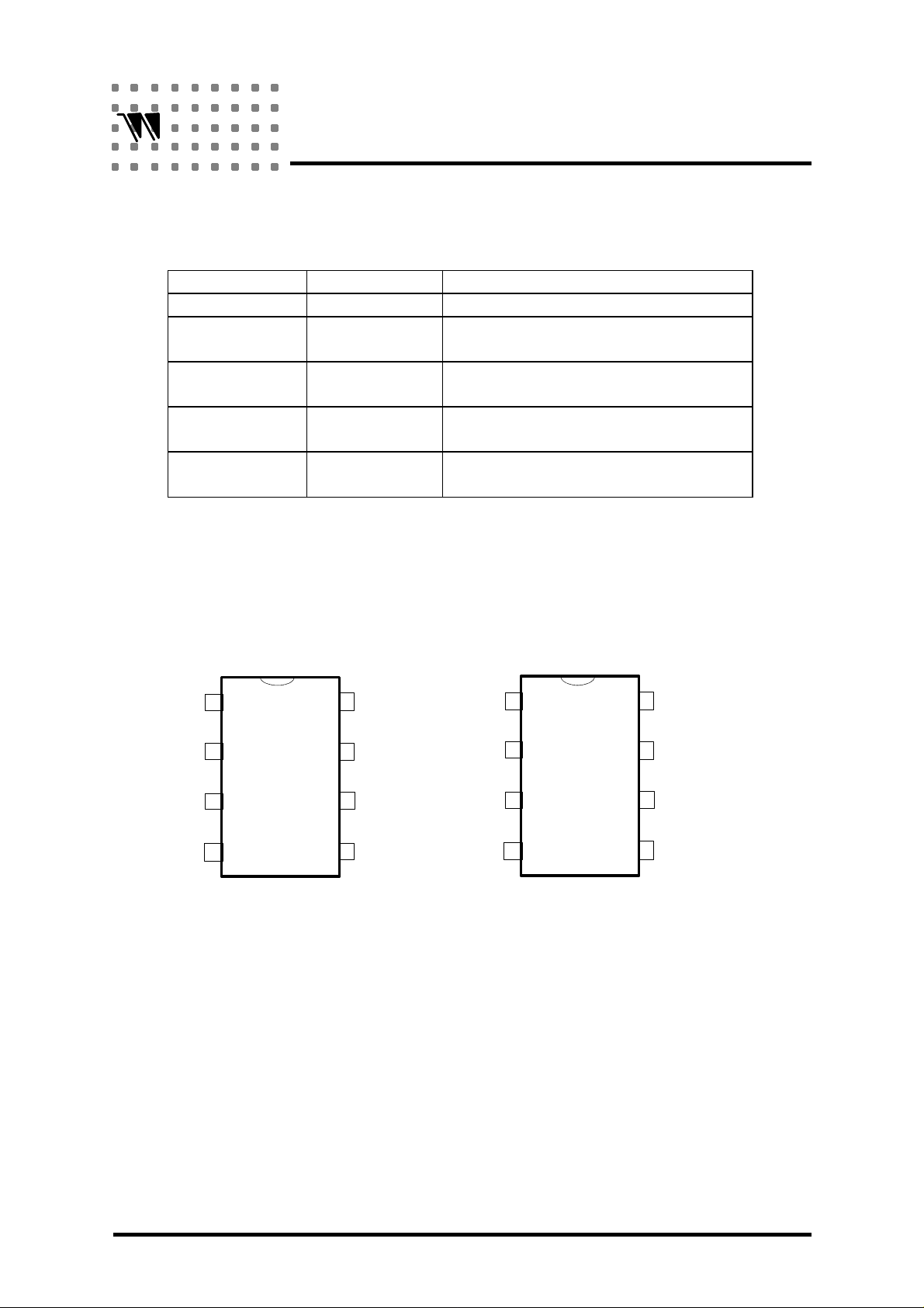
ORDERING INFORMATION
Part No. Package Description
WT8048 P-DIP 8L OSC with 32768Hz Crystal
WT8048N1 P-DIP 8L 1. OSC with external resistor
WT8048N2 P-DIP 8L 1. OSC with external resistor
*WT8048N3 P-DIP 8L 1. OSC with 3.58MHz resonator
*WT8048N4 P-DIP 8L 1. OSC with 3.58MHz resonator
Note: "*" means "not available".
WT8048
2. With mute function
2. Without mute function
2. With mute function
2. Without mute function
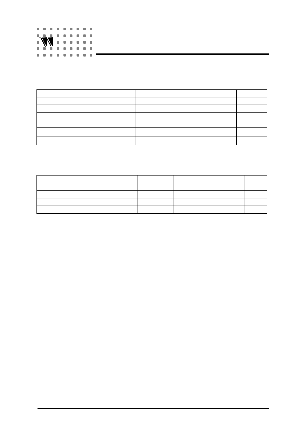
PIN CONFIGURATION
WT8048N1 / N3
HIN
VIN
OSC
VSS
2
3
4
81
7
6
5
VDD
OFF
STD_BY +
SUSPEND
MUTE
WT8048 / N2 / N4
HIN
VIN
OSC
VSS
2
3
4
81
7
6
5
VDD
OFF
SUSPEND
STD_BY
2
Page 3
eltrend
WT8048
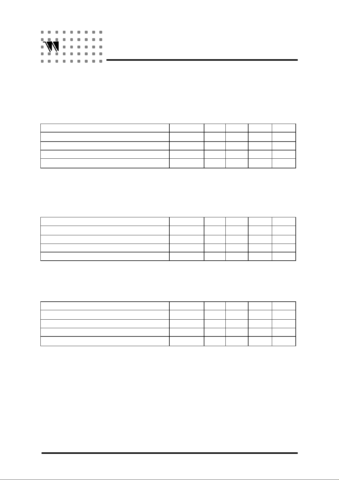
ABSOLUTE MAXIMUM RATING
ITEM SYMBOL VALUE UNIT
Digital Supply Voltage V
Horizontal Sync. Input Voltage V
Vertical Sync. Input Voltage V
Power dissipation P
Operating Temperature Range T
Storage Temperature Range T
DD
HS
VS
D
OPT
STG
RECOMMENDED OPERATING CONDITIONS
ITEM SYMBOL MIN. TYP. MAX. UNIT
Digital Supply Voltage VDD(5) 4.5 5 5.5 V
Supply Current (Stand-by) I
Synchronous Input Voltage Low V
Synchronous Input Voltage High V
P
IL
IH
2.4 4 5.5 V
5.5 V
VDD(5)+0.3 V
VDD(5)+0.3 V
30 mW
0¡ã70 ¢J
-40¡ã125 ¢J
1 mA
0.8 V
PP
PP
PP
PP
3
Page 4
eltrend
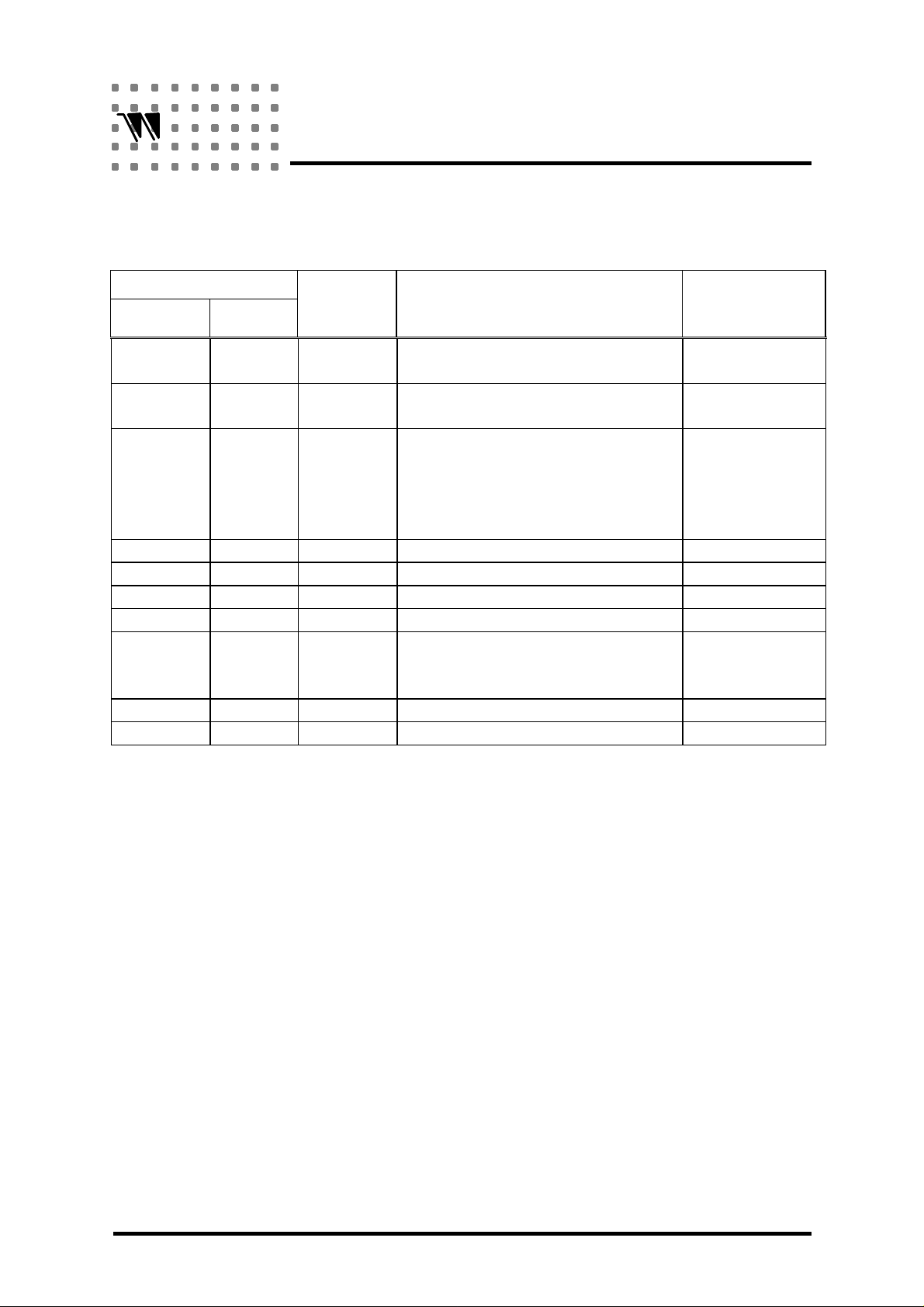
ELECTRICAL CHARACTERISTICS
A. WT8048
WT8048
(VDD=5V, T
=24¢J, F
OPT
=32768Hz)
OSC
ITEM SYMBOL MIN. TYP. MAX. UNIT
Input Current (HIN, VIN), when VIN=5V I
Open Drain Output Low, when IOL = 6mA V
Open Drain Sink Current, when VOL = 0.4V V
Input Current (OSC), when VIN = 5V I
B. WT8048N1 / N2
(VDD=5V, T
=24¢J, F
OPT
= 450KHz)
OSC
ITEM SYMBOL MIN. TYP. MAX. UNIT
Input Current (HIN, VIN), when VIN=5V I
Open Drain Output Low, when IOL = 6mA V
Open Drain Sink Current, when VOL = 0.4V V
Input Current (OSC), when VIN = 5V I
IN1
OL
OL
IN3
IN1
OL
OL
IN3
5
£gA
0.4 V
6 mA
5
5
£gA
£gA
0.4 V
6 mA
15 mA
PP
PP
C. WT8048N3 / N4
(VDD=5V, T
=24¢J, F
OPT
= 3.58MHz)
OSC
ITEM SYMBOL MIN. TYP. MAX. UNIT
Input Current (HIN, VIN), when VIN=5V I
Open Drain Output Low, when IOL = 6mA V
Open Drain Sink Current, when VOL = 0.4V V
Input Current (OSC), when VIN = 5V I
IN1
OL
OL
IN3
5
£gA
0.4 V
6 mA
5
£gA
PP
4
Page 5
eltrend
PIN DESCRIPTION
WT8048
Pin No.
WT8048N1
/N3
1 1 H
WT8048/
N2/N4
Name Function
SIN
Input terminal of horizontal
synchronous signal
2 2 V
SIN
Input terminal of vertical
synchronous signal
3 3 OSC A clock generator circuit is built
into the chip. So, if a resonator is
connected to OSC pin and
ground, a clock signal can be
obtained.
4 4 V
SS
Ground
5 STD_BY Indicate in Stand_By mode
5 Mute Indicate in Mute mode
6 Suspend Indicate in Suspend mode
6 Suspend
+
Indicate in Suspend and stand_By
mode
STD_BY
7 7 Off Indicate in Off mode
8 8 V
DD
5 volts power supply
Structure
of
Terminal
Input,
TTL compatible
Input,
TTL compatible
Input
Output, open drain
Output, open drain
Output, open drain
5
Page 6
eltrend
WT8048
APPLICATION DESCRIPTION
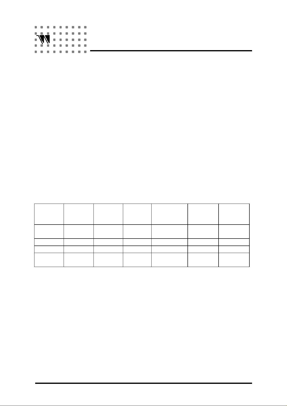
DPMS (Display Power Management Signaling) Dection
As per DPMS proposal WT8048 provides Monitor Power Management Detection Circuit for
the convenience of monitor designers in designing power saving minitors, or the so called
"Green Monitors". Please refer to the table 1 as below for power states defined in the DPMS.
DPMS requires at least 5 seconds delay before transition from ON state to any power saving
state, to avoid unintentionally entering a power saving state during display resoultion changes
and timing mode changes. And it can be done instaneously, for the transition between any
power saving state.
Table 1 Display Power Management Summary
Signals
State
On Pulse Pulses Active Mandatory None Not
Stand-By No Pulses Pulses Blanked Optional Minimal Short
Suspend Pulse No Pulses Blanked Mandatory Substantial Longer
Off No Pulses No Pulses Blanked Mandatory Maximum System
* "No Pulse" represents the frequency of Hsin or Vsin less than or equal to 10Hz,
but "Pulses" represents that frequency of Hsin greater than or equal to 15KHz
(WT8048), 10KHz (WT8048N1 / N2 / N3 / N4) and Vsin greater than or equal
to 40Hz.
Horizontal
Vertical Video
DPMS
Compliance
Requirement
Power
Savings
Recovery
Time
Applicable
Dependent
6
Page 7
eltrend
WT8048
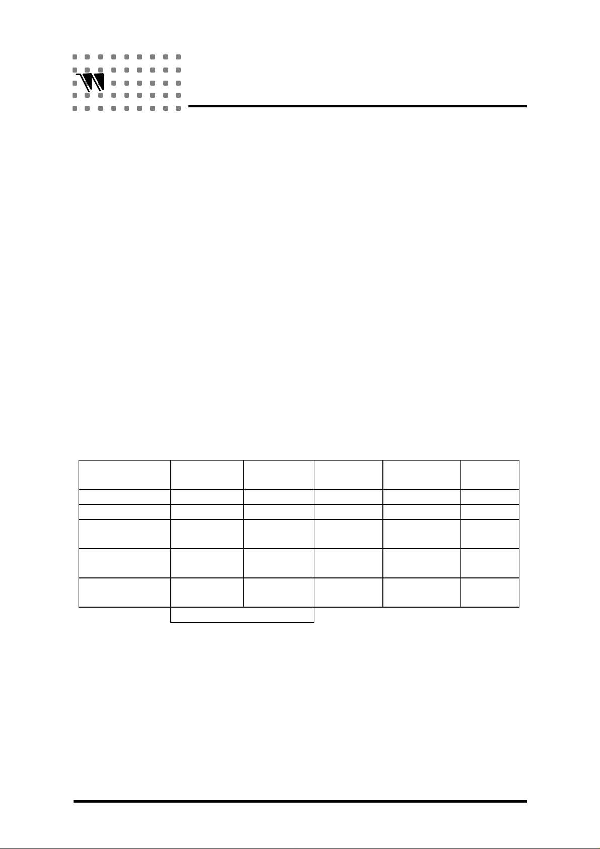
The Way WT8048 implements VESA DPMS
As shown on Table 2, when H_SYNC / V_SYNC signals transition from ON state to any one
of the three power saving state, WT8048 will delay 5.9 seconds to meet the VESA DPMS
requirement: the minimum 5 seconds delay to avoid unintentionally entering a power saving
state during display resolution and timing mode changes. If during this delay time period,
H_SYN and V_SYN signals return to ON state, then all three power management pins will
remain ON state. If power management state of H_SYNC and V_SYNC prolong for more
than 5.9 seconds, then these three power management pins will change to the corresponding
states. While changing from any power saving state back to ON state will take about 0.368
second for H_SYNC / V_SYNC pulse checking. And transition between any power saving
state will be done immediately.
Table 2: The truth table of Power Saving Detector
MODE H
ON Pulses Pulses 1 1 1
STAND_BY No Pulses Pulses 0 1 1
SUSPEND Pulses No
OFF No Pulses No
OVERRIDE No Pulses No
SIN
Manually Power On
V
SIN
Pulses
Pulses
Pulses
STD_B
Y
0 0 1
0 0 0
1 1 1
SUSPEND OFF
7
Page 8
eltrend
WT8048
Synchronization Signals
The basis of DPMS standard is the condition of the synchronization signals to the display.
Two conditions are defined: pulses and no pulses.
{ PULSES
pulses for the Horizontal Sync. Signal are defined as greater than 10KHz repetition
frequency and pulses for the Vertical Sync. Signal are defiened as greater than 40Hz
repetition frequency.
{ NO PULSES
No pulses is defined as less than 10Hz repetition frequency with less than 25% duty cycle
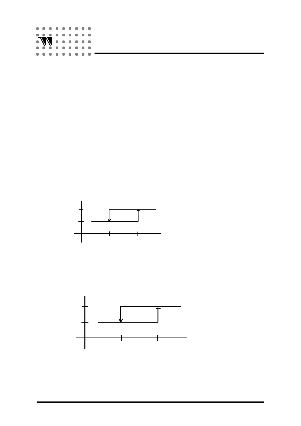
Please refer to the Fig. 1 for the way WT8048 Implement pulses/ no pulses state, between
10Hz and 15KHz / 10KHz, 10Hz and 40Hz. WT8048 use hystersis technique to stable state in
between.
P
NP
P
NP
STATE
10 Hz
f = 15k for WT8048
T
= 10k for WT8048N1/N2/N3/N4
f
STATE
10 Hz
H_SYNC
T
FREQUENCY
V_SYNC
40 Hz
FREQUENCY
Figure 1: pulses / no pulses state implementation
8
Page 9
eltrend
5V
WT8048
OVERRIDE mode
To initiate Override, both the horizontal and vertical sync signals shall be in the no pulses
condition when the display is manually powered on. This condition should be maintained
during the entire time Override is required. As soon as pulses are detected on either horizontal
or vertical sync signal. The display shall enter DPMS operation.
Three power management pins are open drain structure and active low. If you do not need all
those three power saving states in your design. You can just short two or three pins of the
pins: for example, by shorting pin STD_BY and pin Suspend, you will have only two power
saving stated, that is OFF and Suspend states, so you have three states total, including ON
state.
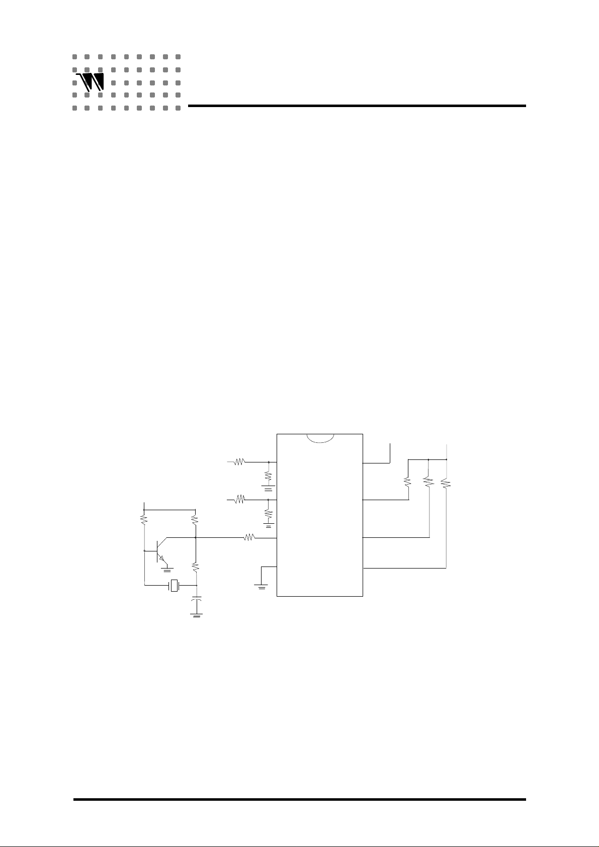
TYPICAL APPLICATION CIRCUIT
WT8048:
3.3M
NOTE:
5V
945
1 2
32768Hz
HSIN
VSIN
10K
680
10K
680
10K
10K
10K
470P
VCC
1
2
3
4
8
7
6
5
1. Transistor: 2SC945¡A£]>300¡C
2. VDD: +5V ± 10%
9
Page 10
eltrend
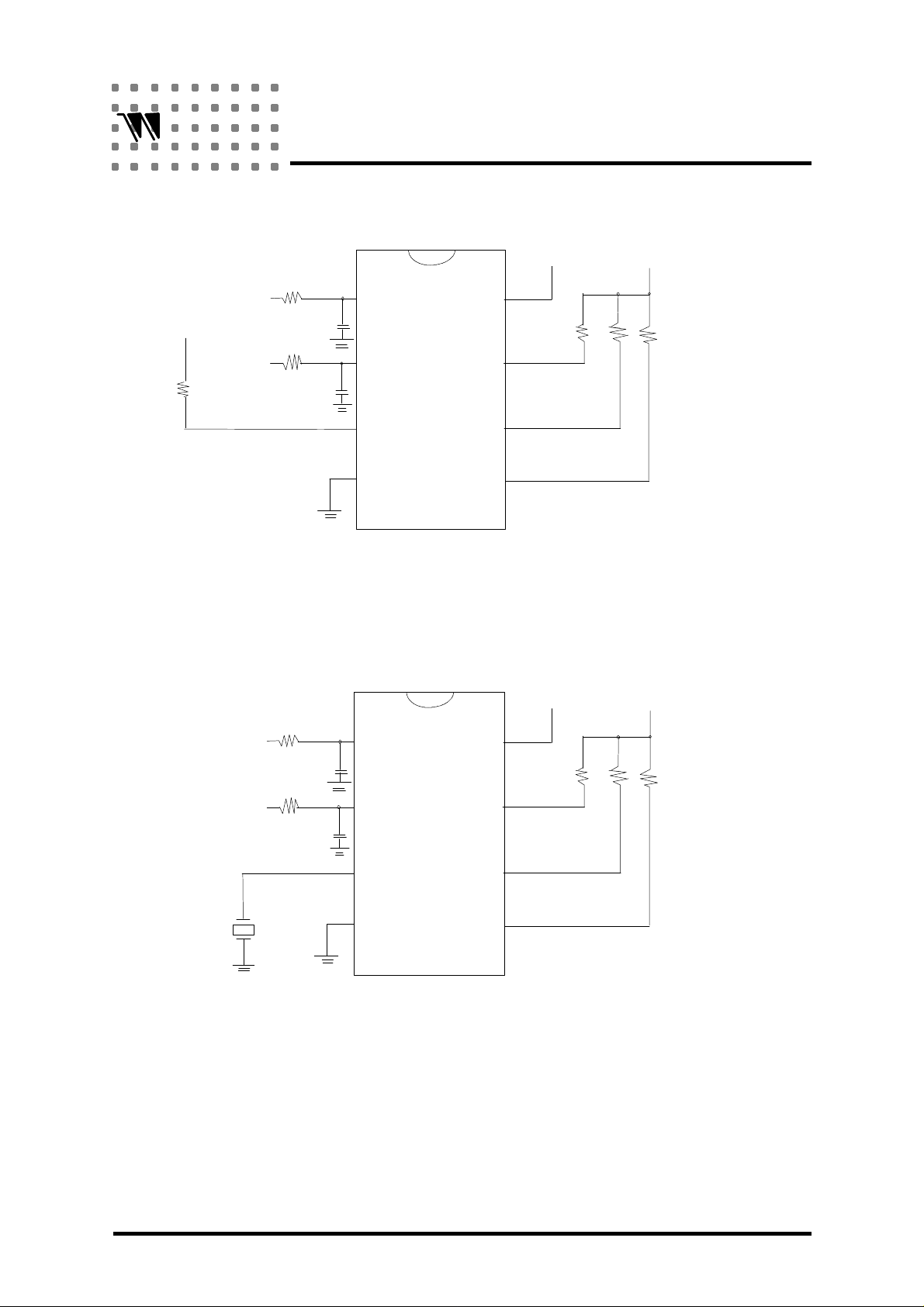
WT8048N1 / N2:
5V
WT8048
VCC
HSIN
VDD
68K
or
75k
NOTE: Connect pin 3 with single resistor for RC oscillation.
WT8048N3 / N4:
VSIN
HSIN
10k
10p
10k
100p
10k
10p
1
2
3
4
1
8
7
6
5
8
5V
Rx
(Pin 5 pull up
Rx for N2 only)
VCC
VSIN
3.58
MHz
NOTE:
1. Connect pin 3 with 3.58MHz resonator have good precision of delay time,
frequency division point.
2. This package is not available for production.
10k
100p
2
3
4
7
6
5
10
 Loading...