

Page 1
3
3
D
3D Models
Design Tools
Videos
www.vishay.com
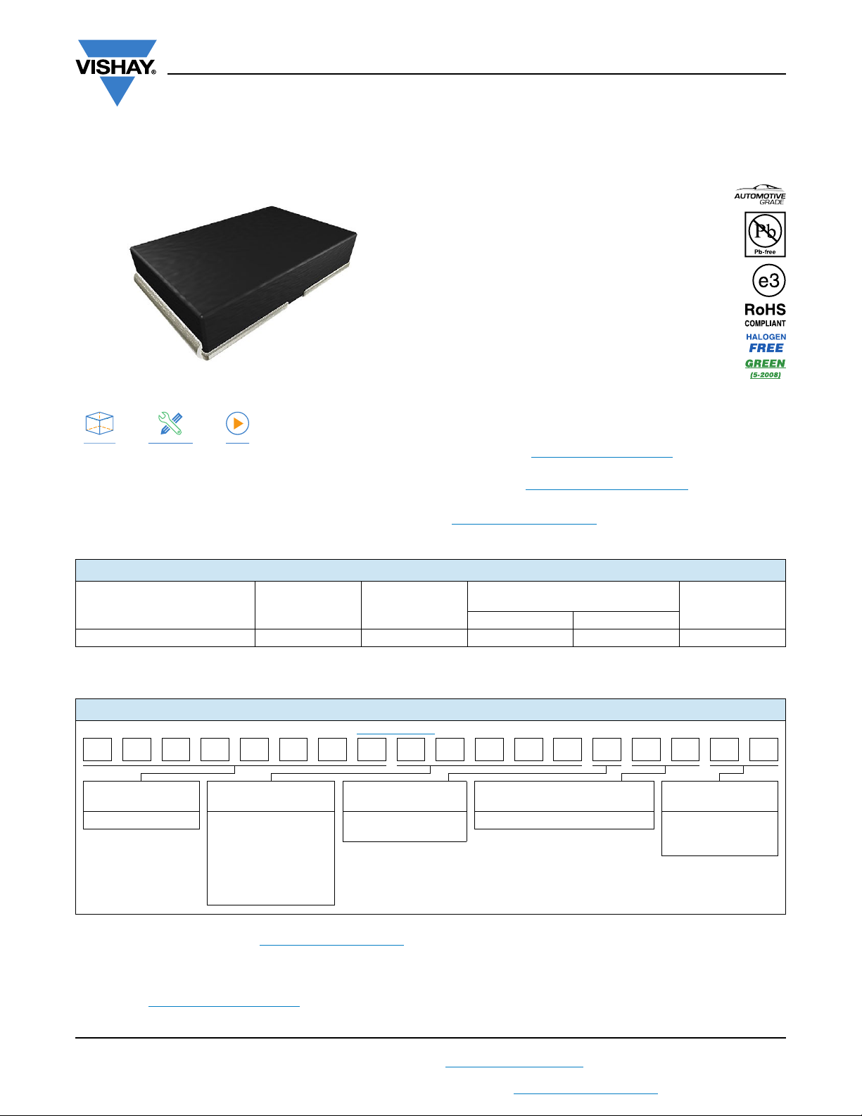
Power Metal Strip® Resistors, High Power (10 W),
Low Value (Down to 0.001 Ω), Surface-Mount
FEATURES
• Improved thermal management incorporated
into design
• All welded construction of the Power Metal Strip
resistors are ideal for all types of current
sensing, voltage division, and pulse applications
• Proprietary processing technique produces
extremely low resistance values
• Sulfur resistance by construction that is
unaffected by high sulfur environments
• Very low inductance (< 5 nH)
• Low thermal EMF (< 3 μV/°C)
LINKS TO ADDITIONAL RESOURCES
Notes
• Follow link to Overview of Automotive Grade Products for more details: www.vishay.com/doc?49924
(1)
Flame retardance test may not be applicable to some resistor technologies
• Solid metal nickel-chrome or manganese-copper alloy
resistive element with low TCR
(< 20 ppm/°C)
• AEC-Q200 qualified
(1)
• PATENT(S): www.vishay.com/patents
• Material categorization: for definitions of compliance
please see
www.vishay.com/doc?99912
WSHP2818
Vishay Dale
STANDARD ELECTRICAL SPECIFICATIONS
POWER RATING
GLOBAL MODEL SIZE
WSHP2818 2818 10
Note
(1)
The WSHP2818 is rated at 10 W with maximum surface temperature of 200 °C based on 70 °C ambient temperature
P
70 °C
W
(1)
RESISTANCE VALUE RANGE
Ω
TOL. ± 0.5 % TOL. ± 1.0 %
0.010 to 0.1 0.001 to 0.1 167.8
WEIGHT
(typical)
g/1000 pieces
GLOBAL PART NUMBER INFORMATION
Global Part Numbering: WSHP2818R1000FEA (visit www.vishay.net Vishay Dale parts numbering manual for all options)
W S H P 2 8 1 8 R 1 0 0 0 F E A
GLOBAL MODEL
(8 digits)
WSHP2818 L = mΩ*
Notes
• SMD Power Metal Strip marking (www.vishay.com/doc?30327)
(1)
EB (lead (Pb) free) is a non-standard packaging code designated for 1000 piece reels. The non-standard packaging code is identical to our
standard EA (lead (Pb) free), except that it has a package quantity of 1000 pieces
RESISTANCE VALUE
(5 digits)
R = decimal
4L000 = 0.004 Ω
R0100 = 0.01 Ω
* Use “L” for resistance
values < 0.01 Ω
TOLERANCE CODE
(1 digit)
D = ± 0.5 %
F = ± 1.0 %
PACKAGING CODE
(2 digits)
EA = lead (Pb)-free, tape/reel (dash number)
(1)
SPECIAL
(up to 2 digits)
from 1 to 99 as
applicable
PATENT(S): www.vishay.com/patents
This Vishay product is protected by one or more United States and international patents.
Revision: 14-Feb-2022
For technical questions, contact: [email protected]
THIS DOCUMENT IS SUBJECT TO CHANGE WITHOUT NOTICE. THE PRODUCTS DESCRIBED HEREIN AND THIS DOCUMENT
ARE SUBJECT TO SPECIFIC DISCLAIMERS, SET FORTH AT www.vishay.com/doc?91000
1
Document Number: 30347
Page 2
f
b
d
a
a
e
l
WSHP2818
www.vishay.com
TECHNICAL SPECIFICATIONS
PARAMETER UNIT RESISTOR CHARACTERISTICS
(4)
± 200
Component temperature coefficient (including terminal)
Element TCR
(2)
(1)
ppm/°C
ppm/°C < 20
for 1 mΩ to 5.99 mΩ
(4)
± 75
for 6 mΩ to 100 mΩ
Inductance nH < 5
Operating temperature range °C -65 to +170
Maximum working voltage
(3)
V(P x R)
1/2
Notes
(1)
Component TCR - total TCR that includes the TCR effects of the resistor element and the copper terminal
(2)
Element TCR - only applies to the alloy used for the resistor element; refer to item 1 in the construction illustration on the following page
(3)
Maximum working voltage - the WSHP is not voltage sensitive, but is limited by power / energy dissipation and is also not ESD sensitive
(4)
Typical TCR is positive, for more details contact factory
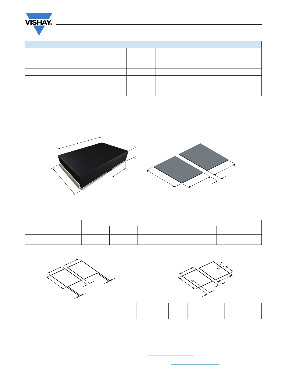
DIMENSIONS in inches (millimeters)
L
Vishay Dale
H
T
W
b
a
a
l
Notes
• 3D models available: www.vishay.com/doc?30349
• Surface-mount solder profile recommendations: www.vishay.com/doc?31052
MODEL
RANGE
Ω
WSHP2818 0.001 to 0.1
RESISTANCE
LWHTabl
0.280 ± 0.010
(7.1 ± 0.25)
DIMENSIONS SOLDER PAD DIMENSIONS
0.180 ± 0.010
(4.6 ± 0.25)
0.059 ± 0.010
(1.50 ± 0.25)
0.125 ± 0.010
(3.18 ± 0.25)
0.138
(3.5)
0.200
(5.1)
0.024
(0.61)
TYPICAL SENSING LAYOUT SENSING WITH VIA LAYOUT (best performance)
a
a
b
l
c
c
abc l
0.138
(3.51)
0.210
(5.33)
0.020
(0.51)
0.024
(0.61)
abde f l
0.143
(3.63)
0.210
(5.33)
0.026
(0.66)
0.105
(2.67)
Ø 0.020
(0.50)
0.024
(0.61)
Note
• Sensing locations are based on the construction of the part; terminals are wrapped from the outside to underneath. These options place the
sensing location nearest the temperature stable resistance element, which minimizes contact resistance and optimizes TCR
Revision: 14-Feb-2022
THIS DOCUMENT IS SUBJECT TO CHANGE WITHOUT NOTICE. THE PRODUCTS DESCRIBED HEREIN AND THIS DOCUMENT
2
ARE SUBJECT TO SPECIFIC DISCLAIMERS, SET FORTH AT www.vishay.com/doc?91000
For technical questions, contact: [email protected]
Document Number: 30347
Page 3
S
A
V
S
S
click to get started
www.vishay.com
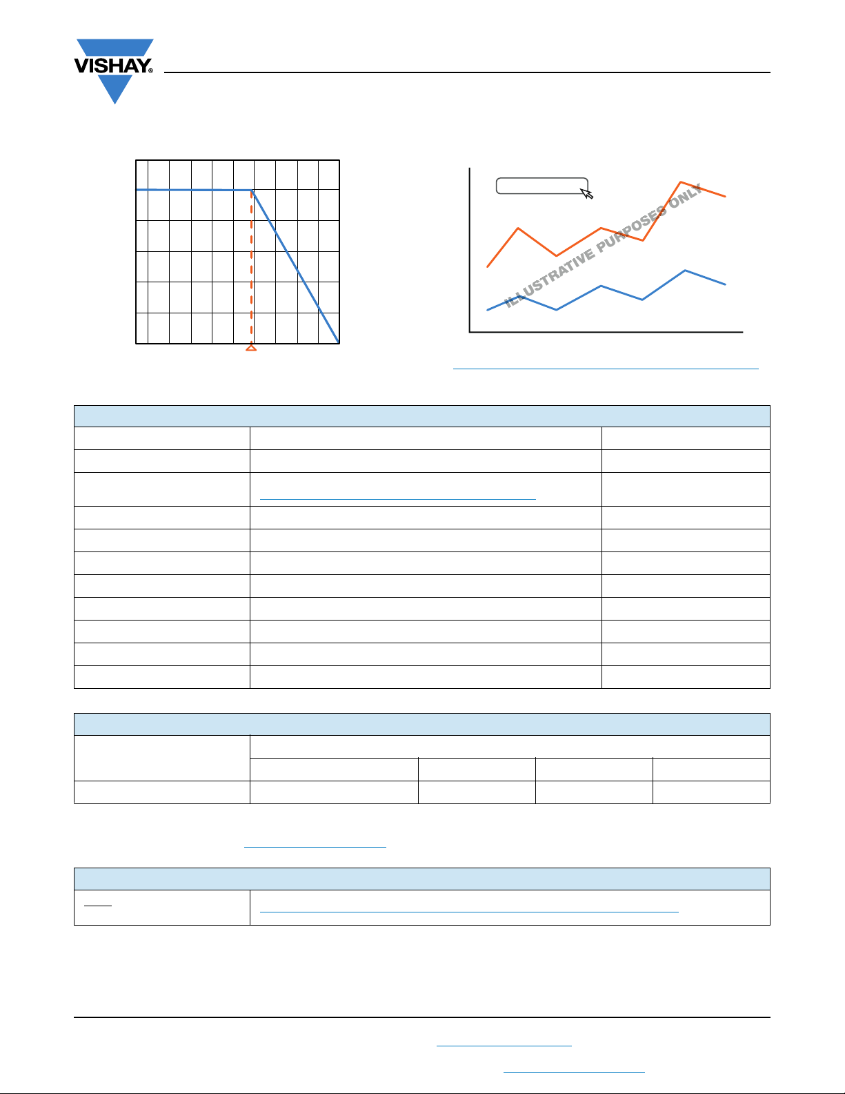
DERATING PULSE CAPABILITY
WSHP2818
Vishay Dale
120
100
80
60
2nd line
40
Rated Power (%)
20
0
-65 -50 -25 0 25 50 100 125 150 170
Axis Title
70
Ambient Temperature (°C)
10000
1000
100
10
1st line
2nd line
www.vishay.com/resistors/power-metal-strip-calculator
PERFORMANCE
TEST CONDITIONS OF TEST TEST LIMITS
Thermal shock -55 °C to +150 °C, 2000 cycles, 15 min at each extreme ± 0.5 %
Short time overload
Low temperature operation -65 °C for 24 h ± 0.5 %
High temperature exposure 2000 h at +170 °C ± 1.0 %
Bias humidity +85 °C, 85 % RH, 10 % bias, 1000 h ± 0.5 %
Mechanical shock 100 g’s for 6 ms, 5 pulses ± 0.5 %
Vibration Frequency varied 10 Hz to 2000 Hz in 1 min, 3 directions, 12 h ± 0.5 %
Load life 2000 h at 70 °C, 1.5 h “ON”, 0.5 h “OFF” ± 1.0 %
Resistance to solder heat +260 °C solder, 10 s to 12 s dwell, 25 mm/s emergence ± 0.5 %
Moisture resistance MIL-STD-202, method 106, 0 % power, 7b not required ± 0.5 %
Refer to link for short time overload performance and pulse capability;
www.vishay.com/resistors/power-metal-strip-calculator/
± 1.0 %
PACKAGING
MODEL
WSHP2818 16 mm/embossed plastic 330 mm / 13" 3500 EA
Notes
• Embossed carrier tape per EIA-481
• Additional packaging details at www.vishay.com/doc?20051
TAPE WIDTH DIAMETER PIECES/REEL CODE
ADDITIONAL RESOURCES
Video: Power Metal Strip
Short Time Overload
Revision: 14-Feb-2022
THIS DOCUMENT IS SUBJECT TO CHANGE WITHOUT NOTICE. THE PRODUCTS DESCRIBED HEREIN AND THIS DOCUMENT
ARE SUBJECT TO SPECIFIC DISCLAIMERS, SET FORTH AT www.vishay.com/doc?91000
www.vishay.com/videos/resistors/vishay-dale-power-metal-strip174-wshmwshp.html
For technical questions, contact: [email protected]
REEL
3
Document Number: 30347
Page 4

Legal Disclaimer Notice
www.vishay.com
Vishay
Disclaimer
ALL PRODUCT, PRODUCT SPECIFICATIONS AND DATA ARE SUBJECT TO CHANGE WITHOUT NOTICE TO IMPROVE
RELIABILITY, FUNCTION OR DESIGN OR OTHERWISE.
Vishay Intertechnology, Inc., its affiliates, agents, and employees, and all persons acting on its or their behalf (collectively,
“Vishay”), disclaim any and all liability for any errors, inaccuracies or incompleteness contained in any datasheet or in any other
disclosure relating to any product.
Vishay makes no warranty, representation or guarantee regarding the suitability of the products for any particular purpose or
the continuing production of any product. To the maximum extent permitted by applicable law, Vishay disclaims (i) any and all
liability arising out of the application or use of any product, (ii) any and all liability, including without limitation special,
consequential or incidental damages, and (iii) any and all implied warranties, including warranties of fitness for particular
purpose, non-infringement and merchantability.
Statements regarding the suitability of products for certain types of applications are based on Vishay's knowledge of typical
requirements that are often placed on Vishay products in generic applications. Such statements are not binding statements
about the suitability of products for a particular application. It is the customer's responsibility to validate that a particular product
with the properties described in the product specification is suitable for use in a particular application. Parameters provided in
datasheets and / or specifications may vary in different applications and performance may vary over time. All operating
parameters, including typical parameters, must be validated for each customer application by the customer's technical experts.
Product specifications do not expand or otherwise modify Vishay's terms and conditions of purchase, including but not limited
to the warranty expressed therein.
Hyperlinks included in this datasheet may direct users to third-party websites. These links are provided as a convenience and
for informational purposes only. Inclusion of these hyperlinks does not constitute an endorsement or an approval by Vishay of
any of the products, services or opinions of the corporation, organization or individual associated with the third-party website.
Vishay disclaims any and all liability and bears no responsibility for the accuracy, legality or content of the third-party website
or for that of subsequent links.
Except as expressly indicated in writing, Vishay products are not designed for use in medical, life-saving, or life-sustaining
applications or for any other application in which the failure of the Vishay product could result in personal injury or death.
Customers using or selling Vishay products not expressly indicated for use in such applications do so at their own risk. Please
contact authorized Vishay personnel to obtain written terms and conditions regarding products designed for such applications.
No license, express or implied, by estoppel or otherwise, to any intellectual property rights is granted by this document or by
any conduct of Vishay. Product names and markings noted herein may be trademarks of their respective owners.
© 2023 VISHAY INTERTECHNOLOGY, INC. ALL RIGHTS RESERVED
Revision: 01-Jan-2023
1
Document Number: 91000
 Loading...