

Page 1
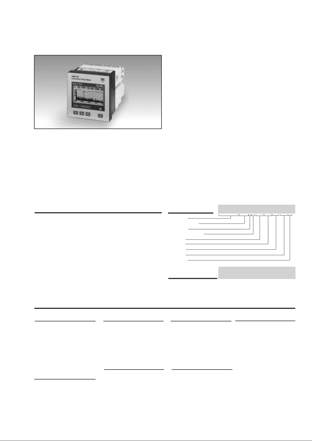
Energy Management
Modular Universal Utility Meter and Power Analyzer
Type WM4-96
• Class 0.5 (current/voltage)
• Universal meter: energy, water and gas
• 32-bit µP-based multifunction power analyzer
• Back-lighted graph display (128x64 dots)
• Front size: 96x96 mm
Measurement of single phase and system instantaneous
•
variables: W, W
Hz, THD (for all measurements max and min values)
•
Measured energies: kWh and kvarh on 4 quadrants
• Graphic display of the load profile (daily, weekly,
monthly display)
• Current and voltage inputs with autoranging capability
• 4x4 dgt instantaneous variable read-out
• 4x9 dgt total energies read-out
• 4x6 dgt partial energies read-out
, var, var
dmd
, VA, VA
dmd
dmd
, PF, PF
avg
, V, AL,
An,
• Optional RS 422/485 serial output
• Optional RS232 + real time clock function and 2Mb
data logging of alarms, MIN/MAX events and up to 8
variables with programmable time interval.
• MODBUS RTU, JBUS protocol
ransmission and reception of SMS messages (vari-
•T
ables and alarm status)
•
Data transmission and reception by means of analogue modem
• Up to 4 optional pulse outputs
• Up to 4 optional alarm outputs
• Universal power supply
• Front degree protection: IP 65
: 18-60VAC/VDC, 90-260 VAC/VDC
Product Description
Universal utility meter and
power analyzer which can be
used in 3 different operating
modes:
- direct measurements for the
power quality analysis (LV or
MV/HV connection);
- indirect energy and power
measurements by means of
watt-hour meters (LV or
MV/HV connection);
direct measurements for the
instantaneous variables (LV
connection) and indirect
measurements for the energy variables (LV or MV/HV).
It’s possible to add the
management of gas and
water metering to all of
these working modes.
Automatic transmission of
SMS alarm messages.
Remote read-out from GSM
mobile phones of all the
instantaneous variables, the
last variables available in the
data logging and the energy
meters.
• 48 independent energy meters to be used as single,
dual, multi-time energy management
• Interface with watt-hour meters by means of digital
inputs (+kWh, +kvarh, -kWh, -kvarh)
• Interface with gas and water meters by means of digi-
tal inputs (one water meter, two gas meters to be used
as single or dual time management)
• Display refresh rate: 10 samples/s
•
Harmonic distortion analys (FFT) up to the 50th harmonic
with graphic and numeric indication (current and voltage)
• Harmonics source detection
How to order
Model
Range code
System
Power supply
Slot A
Slot B
Slot C
Slot D
Options
How to order
Wm4Soft Network: programm to download memory data
and to manage a modem. Wm4Soft Remote: programm to
set all the programming parameters.
WM4-96 A V53H XX XX XX XX X
Wm4Soft Network
Wm4Soft Remote
Type selection
Range code (on r
XXX: None
AV5:
240/415 VAC1/5 AAC
(max. 300 V (L-N)/
520 V (L-L) - 6 A)
AV7: 400/690VAC -
1/5 AAC
(max. 480V (L-N) /
830 V (L-L) / 6 A
Power supply
L:
18 to 60V
H: 90 to 260VAC/VDC
equest)
AC/VDC
Slot A (interfacing)
XX:
None
3 universal digital inputs
D2:
+ excitation output
(16-24VDC)
(alarm or pulse)
Slot D
XX:
None
R2: Dual r
O2: Dual open collector
O4:
elay output,
(AC1-8AAC, 250V
(30V/100mADC)
output
Four open collector output (30V/100mADC)
AC)
Slot B (communication)
XX:
None
S1: Serial output,
RS485 multidr
bidirectional
Options
X: None
M: Serial port
RS232+RTC+ 2Mb or
Data memory to store
all events and contin-
ecor
uous r
variables
E1: WEB-server option
op,
d up to 8
Slot C (alarm or pulse)
XX:
None
R1:
Single relay output
(AC1-8AAC, 250VAC)
R2: Dual relay output,
(AC1-8AAC, 250VAC)
O1:
Single open collector
output (30V/100mADC)
O2:
Dual open collector out
(30V/100mADC)
put
D1:
3 digital inputs for volt-
ee contacts
age-fr
D2:
3 universal digital inputs
+ excitation output
(16-24VDC)
-
1
Page 2
M4-96
W
Input specifications
umber of analogue inputs
N
Current 1 (1-phase; system code: 3)
Voltage 1 (1-phase; system code: 3)
Digital inputs
AQ1038 No. of inputs: 3 (voltage-free)
Purpose W
Contact measuring current
AQ1042
Purpose W
Excitation output 16V<+Aux<24VDC Max 15mA
Contact measuring current
Common characteristics
Input frequency Max 20 Hz, dutycycle 50%
Close contact resistance Max 1kΩ
Open contact resistance Min 100kΩ
Insulation 4000VRMS
Max. input number 6 in the configuration:
Accuracy
(display,RS232, RS485) In: 5A, If.s.: 6A
Current (AL1, AL2, AL3) ±0.5% RDG (0.2 to 1.2 In)
(@25°C ±5°C, R.H. ≤60%) ±5mA (0.02 to 0.2 In)
Current (A
) ±1% RDG (0.2 to 1.2 In)
n
Voltage AV5 range: ±0.5% RDG (48 to 300 V
±5°C, R.H. ≤60%) ±1% RDG (84 to 519 V
C
°
(@25
AV7 range: ±0.5% RDG (80 to 480 V
Frequency ±0.1% RDG (40 to 440 Hz)
Active power
°C ± 5°C, R.H. ≤ 60%) ±0.5% (RDG + FS) (PF 0.5 L/C,
(@ 25
Reactive power
(@ 25°C ± 5°C, R.H. ≤ 60%) ±0.5% (RDG + FS) (PF 0.5 L/C,
Apparent power
(@ 25°C ± 5°C, R.H. ≤ 60%) ±0.5% (RDG+ FS)
Energies
(@ 25°C ± 5°C, R.H. ≤ 60%) Active: class 1 according to
3 (3-phase; system code: 3)
4 (3-phase; system code: 3)
measurement synchro-
md
d
nization + var
md
d
and PF
Interfacing with watt-hour meters
+kWh, +kvarh)
(
.
Tariff selection: energy.
<8mA/ 17.5 to 25VDC
Number of inputs: 3 +
excitation
nization + var
output
measurement synchro-
dmd
dmd
and PF
Interfacing with watt-hour meters
(-kWh, -kvarh) or/and
measurements of gas /water m3.
T arif f selection: energy or GAS.
15mA
AQ1038+AQ1042 or 2*AQ1042
Vn: 240VL-N, Vf.s.: 300VL-N
@ 40 to 100 Hz
L-L
±1% RDG (139 to 830 V
Includes also:
frequency , power supply
and output load influences
0.1 to 1.2 In, range AV5) or
(PF 0.5 L/C,
RDG
1%
±
0.1 to 1.2 In, range AV5)
0.1 to 1.2 In, range AV5) or
±1% RDG (PF 0.5 L/C,
1.2 In, range A
0.1 to
to
(0.1
1.2 In, range A
V5)
V5) or
±1% RDG
(0.1 to 1.2 In, range AV5)
EN61036
Reactive: class 2 accor
ding
to EN61268
Ib: 5A, Imax: 6A
0.1Ib: 500mA,
tart-up current: 20mA
S
Un: 240V (AV5), 400V (A V7)
Harmonic distortion 1% FS (FS: 100%)
(@ 25°C ± 5°C, R.H. ≤ 60%)
phase: ±2°; Imin: 0.1Arms;
Imax: 15Ap; Umin: 50V
Umax: 500Vp
.
md
d
Sampling frequency:
6400
samples/s
Additional errors
≤0.3%
Humidity
RDG
Input frequency ≤ 0.4% RDG, 62 to 400 Hz
Magnetic field ≤ 0.5% RDG @ 400 A/m
NOTE: all accuracies are
dmd
.
referred to measurements
carried out with the analogue
input module
Temperature drift
≤200ppm/°C
Sampling rate 6400 samples/s @ 50Hz
Display Graph LCD backlighted
(128x64 dots). Read-out for
the instantaneous variables:
4x4 digit or 4x3
Total energies: 4x9 digit;
Partial energies: 4x6 digit
Max. and min. indication Max. 9999 (999,999,999),
Min. -9999 (–999,999,999)
Measurements Current, voltage, power,
energy ,power factor,frequency, harmonic distortion(see
“Display Pages”). TRMS
measurement of a distorted
)
L-N
Coupling type Direct.
)
)
est factor
Cr
L-N
)
L-L
wave (voltage/curr
3, max. 15Ap/500Vp “A
≤
(L-N), 15Ap/800Vp “AV7” (L-N)
Ranges (impedances)
AV5 58/100 V (> 500 kΩ) -
≤
1 AAC (
58/100 V (> 500 k
5 AAC (
≤ 0.3 VA)
240 V/415 V (> 500 kΩ) 1 AAC (≤ 0.3 VA)
240 V/415 V (> 500 kΩ) 5 AAC (≤ 0.3 VA)
AV7 100/170 V (> 500 kΩ) -
1 AAC (≤ 0.3 VA)
100/170 V (> 500 k
≤ 0.3 VA)
5 AAC (
400/690 V (> 500 kΩ) 1 AAC (≤ 0.3 VA)
400/690 V (> 500 kΩ) 5 AAC (≤
Frequency 40 to 440 Hz
Overload protection
Continuous: voltage/current: AV5: 300V
V7: 480V
A
For 1s: voltage/current: AV5: 600V
AV7: 960V
@ 50Hz
, 60% to90% R.H.
1
/2digit
ent) .
0.3 VA)
) -
Ω
) -
Ω
0.3 VA)
L-N
L-N
/1040V
L-N
/1660V
L-N
/ 500V
/ 830V
L-L
L-L
L-L
L-L
/ 6A
/ 6A
/120A
/120A
RMS
V5
;
”
2
Page 3
WM4-96
Output specifications
RS422/RS485
(on request) Multidrop
idirectional (static and
b
dynamic variables)
onnections 2 or 4 wires, max. distance
C
1200m, termination
directly on the module
Addresses
from 1 to 255, key-pad selectable
Protocol MODBUS RTU/JBUS
Data (bidirectional)
Dynamic (reading only) All display variables, see
lso the table, “List of the
a
onnected variables”.
tatic (writing only) All configuration parameters
S
c
energy reset, activation of
digital outputs.
Data format 1 start bit, 8 data bit, no
parity/even parity/
odd parity, 1 stop bit
Baud rate 1200, 2400, 4800 and 9600
bit/s selectable
Insulation By means of optocouplers,
4000 V
output to
RMS
measuring inputs
4000 V
output to
RMS
power supply input
RS232
((oonn rreeqquueesstt)
)
Bidirectional (static and
dynamic variables)
Connections 3 wires, max. distance15m
Data format 1 start bit, 8 data bit,
no parity, 1 stop bit
Baud rate 2400, 4800, 9600,
38400 bit/s
Protocol MODBUS RTU (JBUS)
Other features As per RS422/485
Communication by modem
Analogue modem For the remote communica-
tion of all the data measured
and managed by WM4.
External communication
Modem.
Recommended type: US
Robotics
GSM Modem For the transmission of
SMS messages:
alarms, instantaneous
variables, last available
variables of data logging
and energy meters.
The alarms can also be
transmitted automatically,
while the variables can be
ecalled by means of special
r
SMS question codes
GSM kit type-tested for WM4 Siemens kit (external)
model “TC35 TERMINAL”
included GSM module,
antenna and 230V power supply.
Digital outputs (on request)
To be used as alarms and/or
retransmission of the
energy, gas, water metering
and/or
outputs remotely
olled
contr
by the serial
communication port.
The outputs are completely
programmable independently of
the type of module being used.
Pulse outputs (on request)
Number of outputs Up t o 4
Type
From 1 to 1000 pulses
programmable for
k-M-G Wh, k-M-G varh,
open collector (NPN transistor)
V
1.2 VDC/ max. 100 mA
ON
0 VDC max.
3
V
OFF
Outputs connectable to total
and/or partial energy meters
Pulse duration
220 ms (ON), ≥ 220 ms (OFF)
According to DIN43864
Insulation By means of optocouplers,
4000 V
RMS
output to
measuring inputs,
RMS
output to
4000 V
power supply input.
Notes
The outputs can be either open
collector type or relay type
(for the relay output refer to
the specifications described
in the “alarm outputs” section).
Alarm outputs (on request)
Number of set-points Up to 4, independent
Alarm type Up alarm, down alarm
with or without latch ,
phase asymmetry,
phase loss, neutral loss.
Monitoring of the variable All the variables listed at
the paragraph “List of the
connectable variables”.
Set-point adjustment 0 to 100% of the electrical
scale
Hysteresis 0 to 100% of the electrical
scale
On-time delay 0 to 255 s
Relay status Selectable: normally
de-energized or normally
gized
ener
Output type
Relay, SPDT
AC 1-8A, 250V
AC
DC 12-5A, 24VDC
AC 15-2.5A, 250VAC
DC 13-2.5A, 24VDC
Min. response time ≤ 150 ms, filters excluded,
FFT excluded, setpoint
on-time delay: ”0s”
Insulation 4000 V
RMS
output to
measuring input,
RMS
output to
4000 V
power supply input.
Notes The outputs can be either
relay type or open collector
type (for this latter one, see
the specifications
mentioned in the pulse
outputs)
3
Page 4
M4-96
W
Software functions
Password Numeric code of max 3
digits; 2 protection levels of
the programming data
1st level Password “0”: no protection
nd level Password from 1 to 499:
2
ll data are protected
a
Note: by entering in the
programming mode by
means of password, the
measurement is inhibited.
perating mode selection - Direct measurements for
O
the power quality analysis
(L V or MV/HV connection);
- Indirect energy and power
measurements by means of
watt-hour meters (LV or
MV/HV connection);
- Direct measurements for
the instantaneous variables
(LV connection) and indirect
measurements for the energy variables (LV or MV/HV).
It’s possible to add the
management of gas and
water metering to all of
these working modes.
Pulse weight Water/gas meter inputs:
selectable from 1 to
10000 pulses/m
3
, energy
from 1 to 10000.00
imp/kWh/kvarh
Transformer ratio CT up to 30000A (6000)
VT up to 600 kV (6000)
Filters
Filter operating range 0 to 99.9% of the input
electrical scale.
Filtering coefficient 1 to 255
Filter action
Display, alarms, serial outputs
(fundamental variables:
V,A,W and their derived ones).
Event logging Only with RS232+RTC
module+ Data memory
T ype of data Alarms and max./min. (max.
480 events) stor
ed with date
(dd:mm:yy) and hour
(hh:mm:ss) reference, data
logger and load pr
ofile
Sampling management Only for data logger and load
profile. The sample stored
within the selected time interval results from the continuous average of the measur
values. The average is calcu
lated (min. sample) with an
interval within two following
easurements of approx.
m
200 ms.
Data management type: FIFO
Memory size 2 Mbyte
Battery life 10 years
Data logger function The data are stored at time
intervals from 1 to 60 min.; up
to 8 instantaneous variables
can be selected.
Historical data storing time See the “Historical data
storing time table”.
Data format Date: day, month
ime: hours, minutes, seconds,
t
type of stored variable:
variable value.
Load profile Storage at time intervals of
5-10-15-20-30 min of Wdmd.
Historical data storing time 30 weeks: with recording
interval of 5min.
90 weeks: with storing
interval of 15min.
Data format Wdmd variable value, min-
utes, seconds, day, month.
Displaying 4 variables per page
1 page that can be layed out
by the user
30 fixed pages
Energy meters Up to 12 pages depending on
the selected tariff mode. Dis-
playing of the consumed
energy up to two months pre-
ceding the current one by
means of password (depend-
ing on the selected tariff mode).
Water and gas meters 1 page with two displaying
modes depending on the
selected one:
water and gas m
day-time and night gas m
Stored events 240 pages.
Display of the data by means
of password.
Data logger
Display of the data by means
of password with reset func-
tion of the relevant memory
section.
Load profile 3 pages, daily, weekly and
monthly graphic display.
Reset function of the r
memory section by means of
password.
ed
Display language Selectable:
-
Italian, English, French, Ger
man, Spanish
3
or
3
.
elevant
-
Wm4Soft software: parameter programming and memory data transfer
Wm4Soft Network English language softwar
to transfer memory data and
write messages to be
coupled to the SMS alarms,
plus modem
communication
4
e
management. The p rog r a m
runs under Windows
/95/98/98SE/2000/NT/XP
Working mode Three differ ent working
modes can be selected:
- management of a local
.
Page 5
WM4-96
Wm4Soft software: memory data transfer (cont.)
S485 network;
R
- management of modem
ommunication from a single
c
instrument to PC (data download);
- management of modem
communication from local
networks (RS485 communication) to a common PC
data download).
ata Storing In pre-formatted XLS files
D
Data T ransfer Manual or automatic at
(
Excel data base).
(
The instantaneous and the
energy , gas, water variables
are stored into two separated
files.
programmable timings.
Modem communication Phone book management
m4Soft Remote
W
Data access By means of RS232 serial
General Specifications
(save up to 100 numbers).
Each number is associated to
a modem that corresponds
ither to the single instrument
e
or to a network of instruments.
Each network can manage up to
10 local instruments.
nglish language software
E
o program the working
t
parameters of the instrument
The program runs under
Windows 95/98/98SE/2000/
NT/XP.
port to be coupled to a GSM
or analogue modem or
RS485 port (also multi-drop
availability.).
Operating 0 to +50°C (32 to 122°F)
Temperature
Storage -10 to +60°C (14 to 140°F)
temperature
Insulation reference
voltage 300 V
Insulation 4000 V
Dielectric strength 4000 V
Noise Rejection
CMRR
EMC IE C EN 61000-6-2,
(R.H. < 90% non-condensing)
(R.H. < 90% non-condensing)
RMS
to ground (AV5 input)
RMSbetween all inputs/
outputs to ground
RMS
for 1 minute
100 dB, 48 to 62 Hz
IEC EN 61000-6-3
Other standards
Safety IEC 61010-1, EN 61010-1
Product Energy measurements:
Pulse output DIN43864
Approvals CE, UL and CSA
Connector Screw-type
Housing
Dimensions 96x96x140 mm
Material ABS,
Protection degree Front: IP65,
Weight Approx. 600 g
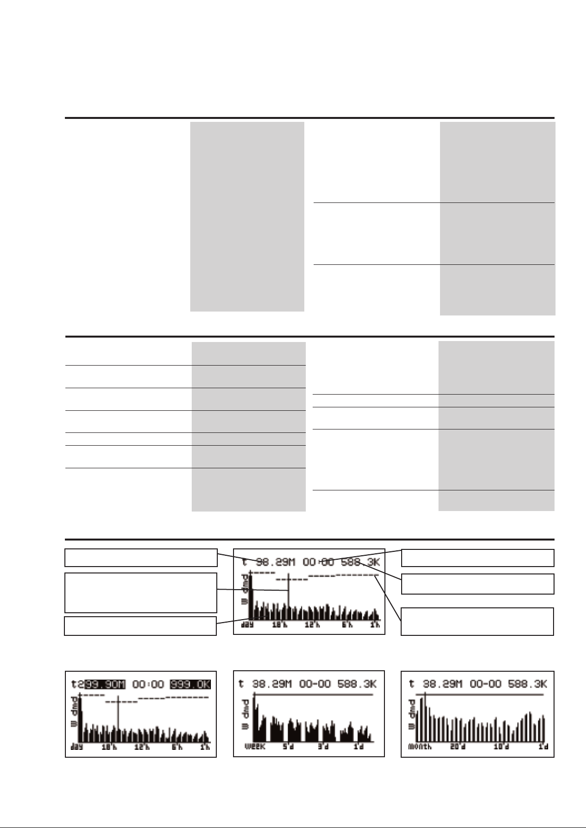
Load profile display
Installed power
Example: the consumed power integrated in 15 minutes exceeds the
installed power
Graph of consumptions
By means of the “F” key you can display the single integration time periods and the details r
power programmed for that time period, the storing time of the Wdmd sample and the relevant value.
Time of the last integration
Wdmd of the last integration period
Profile of the installed power divided
into time periods
elating to the value of the installed
EN61036, EN61268.
max. 2.5 mm2 wires (2x 1.5mm2)
self-extinguishing: UL 94 V-0
NEMA4x, NEMA12
(packing included)
Daily graph: resolution of 15 minutes,
total time of 24 hours.
Weekly graph: resolution of 2 hours,
total time of 7 days.
Monthly graph: resolution of 12 hours,
maximum total time of 31 days.
5
Page 6
M4-96
trftrf
endend
startstart
WINTERWINTER
11
OO:OOOO:OO
O6:OOO6:OO
22 O6:OOO6:OO
O8:OOO8:OO
33 O8:OOO8:OO
1O:OO1O:OO
TARIFFTARIFF
11
trf1
24
6
12
18
2
4
8
10
14
16
20
22
trf2
trf2 trf3
trf3
trf4
trf1
trftrf
WINTERWINTER
22
1O:OO1O:OO
16:OO16:OO
33 16:OO16:OO
18:OO18:OO
44 18:OO18:OO
21:OO21:OO
TARIFFTARIFF
11
11 21:OO21:OO
OO:OOOO:OO
startstart
endend
W
Supply specifications
AC/DC voltage 90 to 260V (standard)
18 to 60V (on request)
Power consumption ≤30VA/12W (90 to 260V)
≤20VA/12W (18 to 60V)
Harmonic distortion analysis
Analysis principle FFT
Harmonic measurement
Current Up to the 50thharmonic
Voltage Up to the 50
T ype of harmonics THD (V
THD odd (V
THD even (V
L1)
h
t
harmonic
L1)
L1)
The same for the other phases:
L2, L3.
THD (A
L
1)
L
THD odd (A
THD even (A
L
1)
1)
The same for the other phases:
L2, L3.
Harmonic phase angle The instrument measures the
angle between the single harmonic of “V” and the single
harmonic of “I” of the same
order . Accor ding to the value
of the electrical angle, it is
Harmonic details The harmonic contents is dis-
System The harmonic distortion
possible to know if the distortion is absorbed or generated.
Note: if the system has 3
wires the angle cannot be
measured.
played as a graph showing
the whole harmonic spectrum. This value is also given
as a numerical information:
THD % / RMS value
THD even % / RMS value
THD odd% / RMS value
single harmonics in % /
RMS value
can be measured in singlephase, 3-wire or 4-wire
systems.
Tw: 0.02
Time period management (energy, water and gas metering)
Time periods Energy
Selectable: single time, dual
time and multi-time
Single time Energy
, water, gas
Nu m b e r o f m e t e r s T otal: 4 (9-digit)
(no partial meters)
Dual time Energy, gas
Nu m b e r o f m e t e r s T otal: 4 (9-digit)
Partial: 8 (6-digit);
Time periods 2, programmable within
24 hours
Multi-time Energy
otal: 4 (9-digit)
Number of meters
T
Partial: 48 (6-digit);
Time periods 4, programmable within
24 hours
Time seasons 3, programmable within
12 months;
Pulse output Connectable to total and/or
partial meters (dual time,
multi-time periods)
Energy metering recording Energy consumption history ,
ecording of energy metering
r
by months, oldest data:
2 months before current date.
Recording of total and partial
6
ener
Energy metering recording
(EEPROM)
Max.999,999,999.99kWh/kvarh.
gy metering.
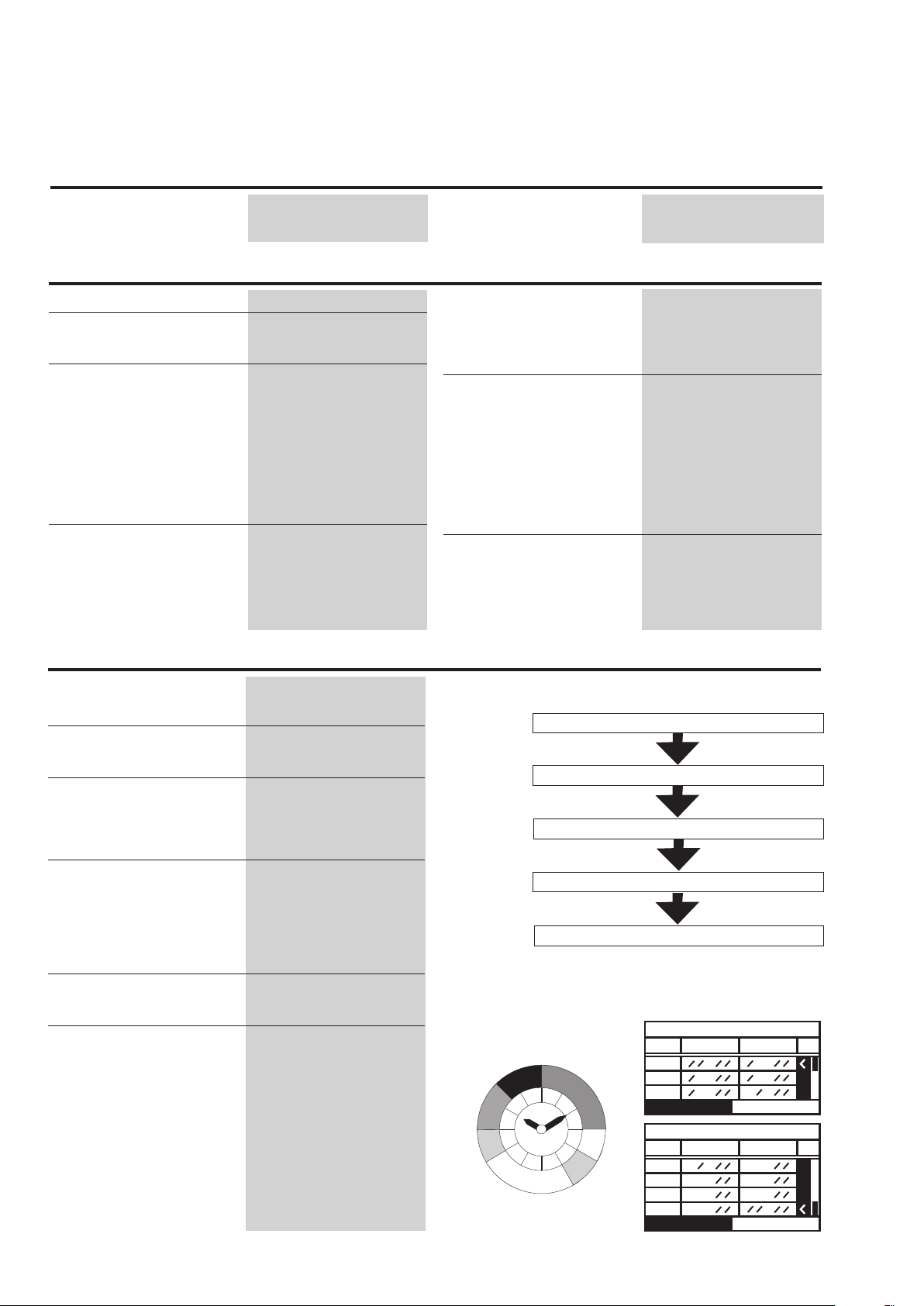
Management concept (multi-time)
(a)
+Wh, +varh (-Wh, -varh)*
max. 4
(b)
Time period (24 hours)
max. 3
(c)
Season (12 months)
Partial: up to 48 meters (a x b x c)
Total: up to 4 meters (“a” type)
* Only if measuring analogue inputs are present.
Example of multi-time energy metering
Page 7
WM4-96
Display pages
Display variables in three-phase systems, 4-wire connections
No 1st variable 2nd variable 3rd variable 4th variable Note
0
1 V L1 V L2 V L3 V L-N sys Sys = system =
2 V L1-2 V L2-3 V L3-1 V L-L sys Sys = system =
3
4 W L1 W L2 W L3 W sys Sys = system =
5
6 VA L1 VA L2 VA L3 VA sys Sys = system =
7 PF L1 PF L2 PF L3 PF sys
8 V L1 A L1 PF L1 W L1
9 V L2 A L2 PF L2 W L2
10 V L3 A L3 PF L3 W L3
11 V sys PF sys var sys W sys Sys = system =
12 An PF sys Hz W sys Sys = system =
13 W dmd var dmd PF avg VA dmd
14 (MAX1) (MAX2) (MAX3) (MAX4) The MAX value can be one of the
15 (MAX5) (MAX6) (MAX7) (MAX8)
16 (MAX9) (MAX10) (MAX11) (MAX12)
17 (MIN1) (MIN2) (MIN3) (MIN4) The MIN value can be one of the
18 (MIN5) (MIN6) (MIN7) (MIN8)
19 Hystogram FFT V1 (THD, THDo, THDe, Single harmonic) Only if analysis V1-A1 are activated
20 Hystogram FFT A1 (THD, THDo, THDe, Single harmonic) Only if analysis V1-A1 are activated
21 Hystogram FFT V2 (THD, THDo, THDe, Single harmonic) Only if analysis V2-A2 are activated
22 Hystogram FFT A2 (THD, THDo, THDe, Single harmonic) Only if analysis V2-A2 are activated
23 Hystogram FFT V3 (THD, THDo, THDe, Single harmonic) Only if analysis V3-A3 are activated
24 Hystogram FFT A3 (THD, THDo, THDe, Single harmonic) Only if analysis V3-A3 are activated
25 kWh + TOT kWh – TOT kvarh + TOT kvarh – TOT
26 kWh+ kWh– kvarh+ kvarh– Partial energy being measured
27 GAS m
Selectable Selectable Selectable Selectable
Σ
Σ
Σ
Σ
A L1 A L2 A L3 An A n = neutral current
ΣΣ
Σ
var L1 var L2 var L3 var sys Sys = system =
Σ
Σ
Σ
Σ
Σ
Σ
Σ
above mentioned (From No 0 to No 13)
above mentioned (From No 0 to No 13)
3
WATER m3 or GAS m3night tariff According to the setting
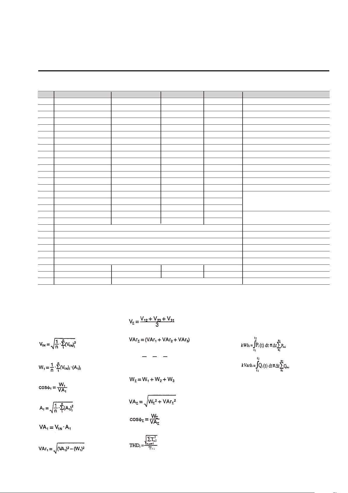
Used calculation formulas
Phase variables
Instantaneous effective voltage
Instantaneous active power
Instantaneous power factor
(TPF)
Instantaneous effective current
Instantaneous appar
ent power
Instantaneous reactive power
System variables
Equivalent three-phase voltage
Three-phase reactive power
Neutral curr
An = AL1+AL2+A
ent
L3
Three-phase active power
Three-phase apparent power
Three-phase power factor
(TPF)
Total harmonic distortion
Where:
i = considered phase (L1, L2 or L3)
T = considered variable (V or A)
n = harmonic order
Energy metering
Where:
i = considered phase (L1, L2 or L3)
= active power
P
Q = reactive power
, t2=starting and ending time points
t
1
of consumption recording
n = time unit
= time interval between two successive
t
∆
power consumptions
n
, n2= starting and ending discr
1
points of consumption recording
ete time
7
Page 8
M4-96
W
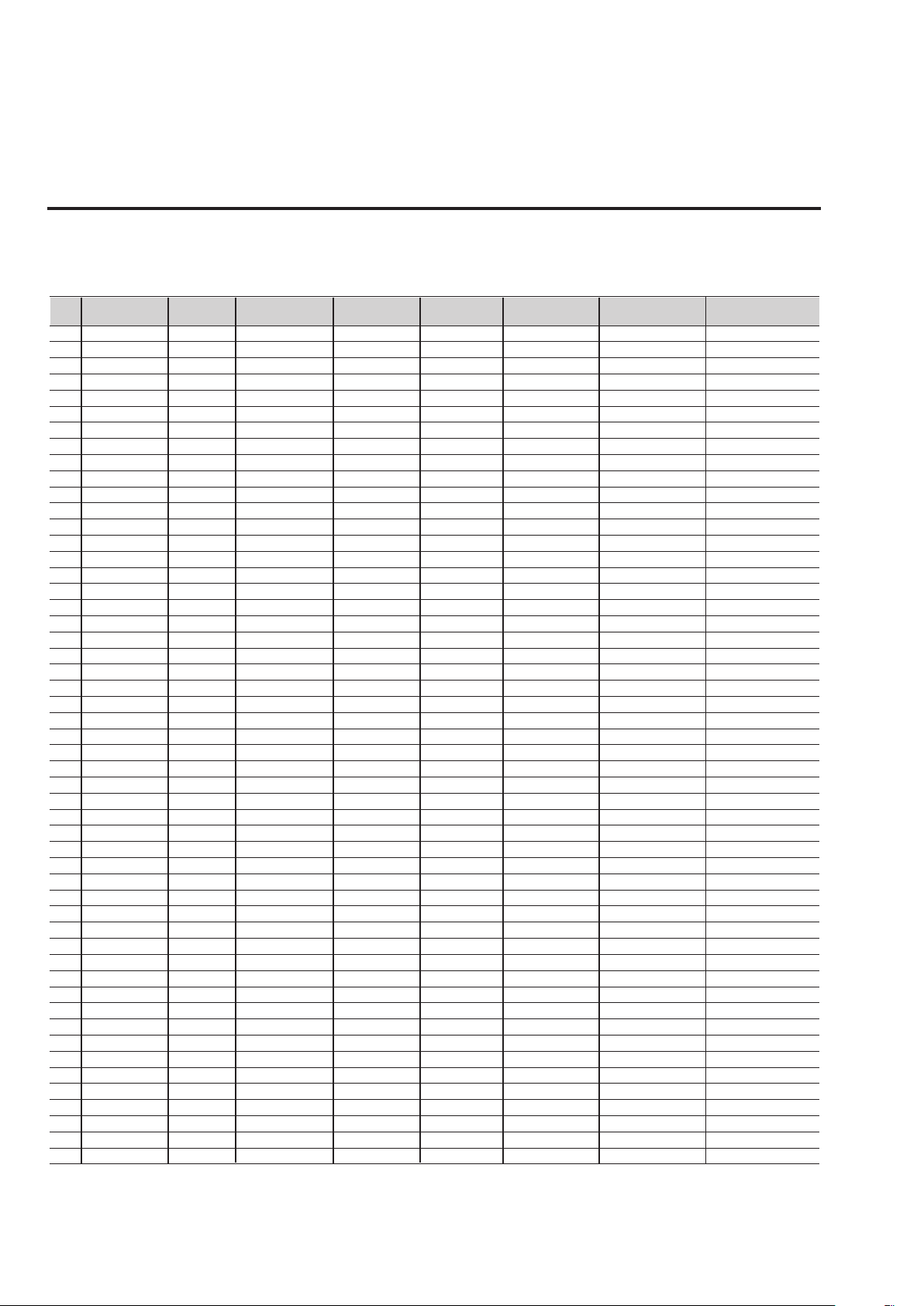
List of the variables that can be connected to:
ax./Min. variable detection
• M
• Alarm outputs
• Pulse outputs
o Variable 1-phase 3-ph. 4-wire 3-ph. 4-wire 3 ph. 3-wire 3 ph. 3-wire meas. module Notes
N
1 V L1 o x x o o o
2 V L2 o x x o o o
3 V L3 o x x o o o
4
5 V L1-2 o x x x x o
6 V L2-3 o x x x x o
7 V L3-1 o x x x x o
8 V L-L sys o x x x x o Sys = system =
9A L1xxxxx o
10
11 A L3 o x x x x o
12An oxxxx o
13
14 W L2 o x x o o o
15 W L3 o xxoo o
16 W sys o x x x x o Sys = system =
17 var L1 x x x o o o
18 var L2 o x x o o o
19 var L3 o x x o o o
20 var sys o x x x x o Sys = system =
21 VA L1 x x x o o o
22 VA L2 o x x o o o
23 VA L3 o x x o o o
24 VA sys o x x x x o Sys = system =
25 PF L1 x x x o o o
26 PF L2 o x x o o o
27 PF L3 o x x o o o
28 PF sys o x x x x o Sys = system =
29Hz xxxxx o
30 THD V1 x x x x x o FFT V1-A1 ON
31 THDo V1 x x x x x o FFT V1-A1 ON
32 THDe V1 x x x x x o FFT V1-A1 ON
33
34 THDo V2 o x x x x o FFT V2-A2 ON
35 THDe V2 o x x x x o FFT V2-A2 ON
36 THD V3 o x x x x o FFT V3-A3 ON
37
38 THDe V3 o x x x x o FFT V3-A3 ON
39
40
41 THDe A1 x x x x x o FFT V1-A1 ON
42 THD A2 o x x x x o FFT V2-A2 ON
43 THDo A2 o x x x x o FFT V2-A2 ON
44 THDe A2 o x x x x o FFT V2-A2 ON
45 THD A3 o x x x x o FFT V3-A3 ON
46
47 THDe A3 o x x x x o FFT V3-A3 ON
48 A dmd x x x x x o
49 VA dmd x x x x x x
50
51 W dmd x x x x x x ◆
52
(x) = available (o) = not available
(
◆) Notes: the alarm outputs can be connected to Wdmd total and/or Wdmd tariff1, Wdmd tariff2, Wdmd tariff3,
Wdmd tariff4.
V L-N sys o x x o o o Sys = system=
A L2 o x x x x o
W L1 x x x o o o
THD V2 o x x x x o FFT V2-A2 ON
THDo V3 o x x x x o FFT V3-A3 ON
THD A1 x x x x x o FFT V1-A1 ON
THDo A1
THDo A3
avg
PF
ASY
system balanced sys. unbal. sys. bal. sys. unbal. sys. not available
x
o
xxxxx x
o
x
x
xxxx o
x x x o FFT V1-A1 ON
x x x o FFT V3-A3 ON
Σ
Σ
Σ
Σ
Σ
Σ
Σ
Σ
Σ
Σ
Σ
Σ
8
Page 9
WM4-96
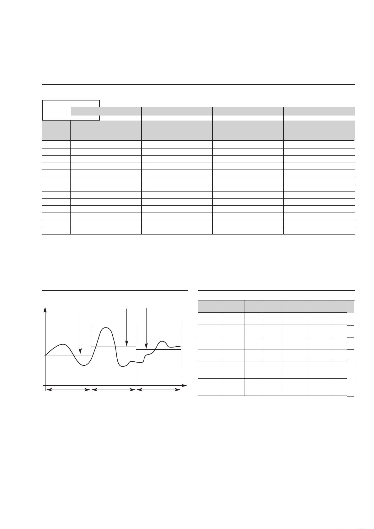
Historical data storing time table
Average
values
only
ime
T
nterval
i
(minutes)
1
5
10
15
20
25
30
35
40
45
50
55
60
2 Selected variables
ata storing time
D
D
AYS WEEK YEARS
22 17 -
1
610 87 1.7
- 174 3.4
- 262 5.0
- 349 6.7
436 8.4
-
- 523 10.1
- 610 11.7
- 697 13.4
- 785 15.1
- 872 16.8
- 959 18.4
- - 20.1
4 Selected variables
ata storing time
D
D
AYS WEEK YEARS
112 -
8
407 58 1.1
814 116 2.2
- 174 3.4
- 232 4.5
291 5.6
-
- 349 6.7
- 407 7.8
- 465 8.9
- 523 10.1
- 581 11.2
- 639 12.3
- 697 13.4
6 Selected variables
ata storing time
D
D
AYS WEEK YEARS
19 -
6
305 44 610 87 1.7
915 131 2.5
- 174 3.4
218 4.2
-
- 262 5
- 305 5.9
- 349 6.7
- 392 7.5
- 436 8.4
- 479 9.2
- 523 10.1
8 Selected variables
ata storing time
D
D
AYS WEEK YEARS
97 -
4
244 35 488 70 1.3
732 105 2
976 139 2.7
174 3.4
-
- 209 4
- 244 4.7
- 279 5.4
- 314 6
- 349 6.7
- 384 7.4
- 418 8
The working mode of data logging The Wm4Soft network potential
Average value of
“n” data sample
t
i
Average value of
“n+1” data sample
t
i
Average value of
“n+2” data sample
t
i
ti= time interval (programmable from 1 to 60 minutes)
Download data files from WM4-96 to PC
Type of
Network
Local
No. of
Network
1
No. of
WM4
1
Port
AR1041
Local
Accessory
None
PC
Accessory
None
(RS232)
Local
1
10
AR1041
None
SIU-PC
AR1034
Remote
Remote
Remote
Remote
100
100
100
100
10
10
1
1
AR1041
(RS232)
AR1041
(RS232)
AR1041
AR1034
(RS485)
AR1041
AR1034
(RS485)
Analogue
modem
GSM
modem
SIU-PC+
analogue
modem
SIU-PC+
GSM
modem
Analogue
modem
Analogue
modem
Analogue
modem
Analogue
modem
◆ Notes:
A- Only data download
B- Data download. Each AR1041 can be connected to a GSM
modem in or
der to manage the SMS messages.
C- The WM4-96 can be set to manage the data download or to
manage SMS messages.
User
PC
PC
PC
PC
PC
PC
◆
A
B
A
C
B
B
9
Page 10
M4-96
W
The available modules
Type N. of Order
hannels code
c
WM4-96 base AD1040
AV5.3 measuring inputs AQ1018
AV7.3 measuring inputs AQ1019
18-60VAC/DC power supply AP1021
90-260VAC/DC power supply AP1020
RS485 port (1) 1 AR1034
Relay output (*) 1 AO1058
Relay output (*) 2 AO1035
Open collector output (*) 1 AO1059
Open collector output (*) 2 AO1036
Open collector output (*) 4 AO1037
Digital inputs 3 AQ1038
Digital inputs + Aux 3 AQ1042
RS232 port + R
TC
+ 2Mb Data memory (1) 1 AR1041
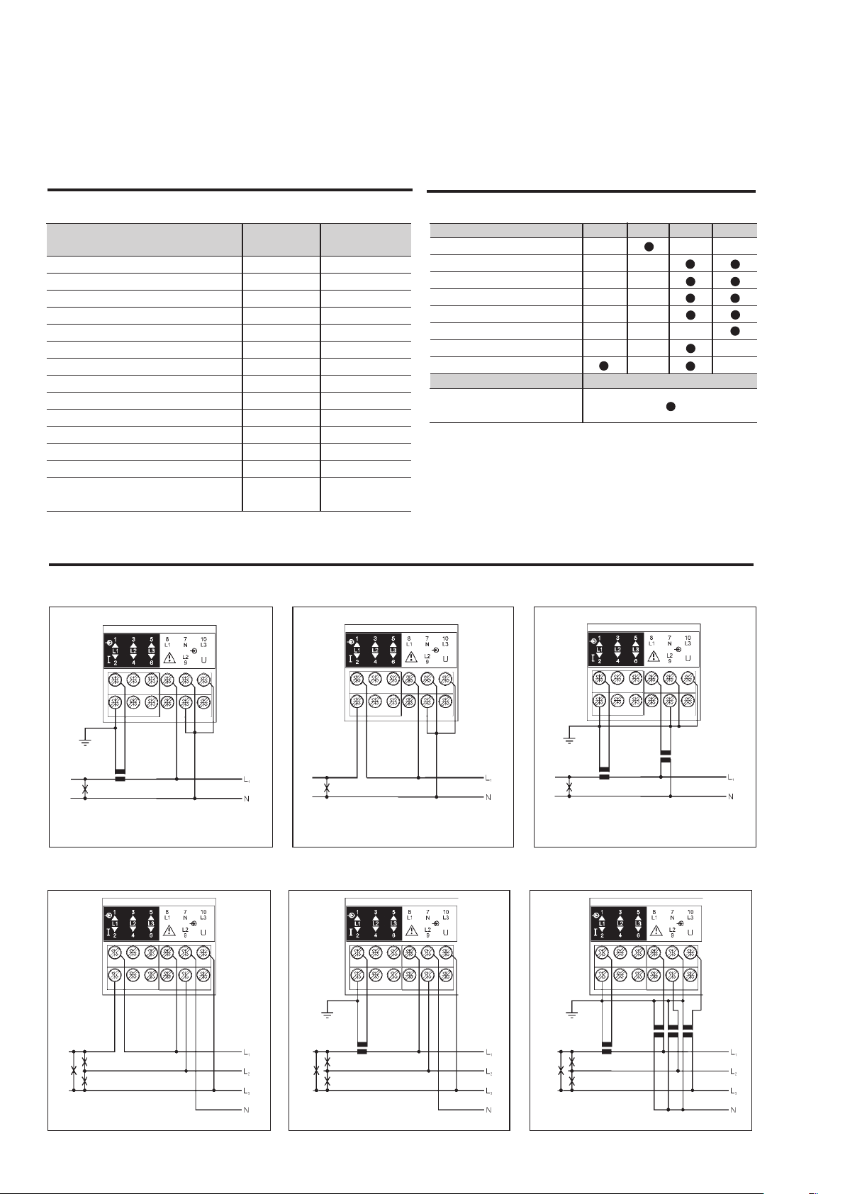
Wiring diagrams
Single phase input connections
The possible module combinations
asic unit Slot A Slot B Slot C Slot D
B
RS485 port
Single relay output (*)
Single open collect. output (*)
Dual relay output (*)
Dual open coll. output (*)
4 open coll. output (*)
3 digital inputs
3 digital inputs + Aux
Basic unit Slot E
RS232 port + RTC
+2 Mb Data memory
(*) Alarm or pulse
(1) The RS232 module works as alternative of the
RS485 module.
Fig. 1
CT connection Direct connection CT and VT connection
ee-phase three-wir
Thr
e input connections - Balanced load
Fig. 4
Fig. 2
Fig. 5
Fig. 3
Fig. 6
10
CT connection (3-wire system)Direct connection (3-wire system)
CT and VT connection (3-wir
e system)
Page 11
WM4-96
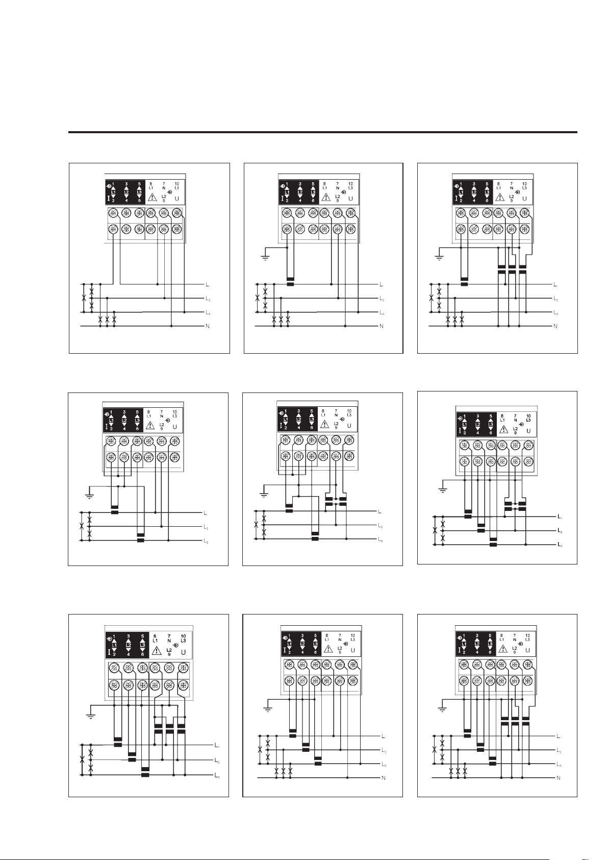
Wiring diagrams (cont.)
hree-phase, four-wire input connections - Balanced load
T
Fig. 7
Direct connection (4-wire system)
Three-phase, three-wire input connections - Unbalanced load
Fig. 10
CT connection (4-wire system)
Fig. 8
Fig. 11
F
CT and VT connection (4-wire system)
Fig. 12
ig. 9
CT connection (3-wire system) ARON
Three-phase, three and four wires input connections
Fig. 13
CT and VT connection (3-wire system) CT connection (4-wire system) CT and VT connection (4-wire system)
CT and VT connection (3-wire system) ARON
- Unbalanced load
Fig. 14
CT and VT connection (3-wire system)
Fig. 15
11
Page 12
M4-96
W
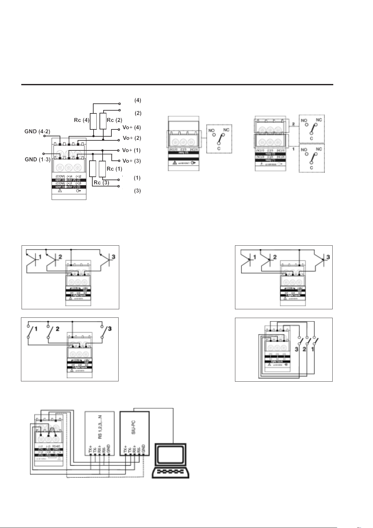
Wiring diagrams of optional modules
VDC
VDC
VDC
VDC
AO1037 4 open collector outputs: The load resistance (Rc) must be designed so that the closed contact current is lower than
100mA; the VDC voltage must be lower than or equal to 30V
VDC: power supply voltage output. Vo+: positive output contact (open collector transistor). GND: ground output contact (open
collector transistor).
AQ1042 digital
input module.
Connection by
means of NPN
transistor.
AQ1042 digital
input module.
Connection by
means of con
tacts.
AO1058 1 relay output
.
-
AQ1042 digital
input module.
Connection by
means of PNP
transistor.
AQ1038 digital
input module.
Connection by
means of con
tacts.
AO1035 2 relay outputs
-
12
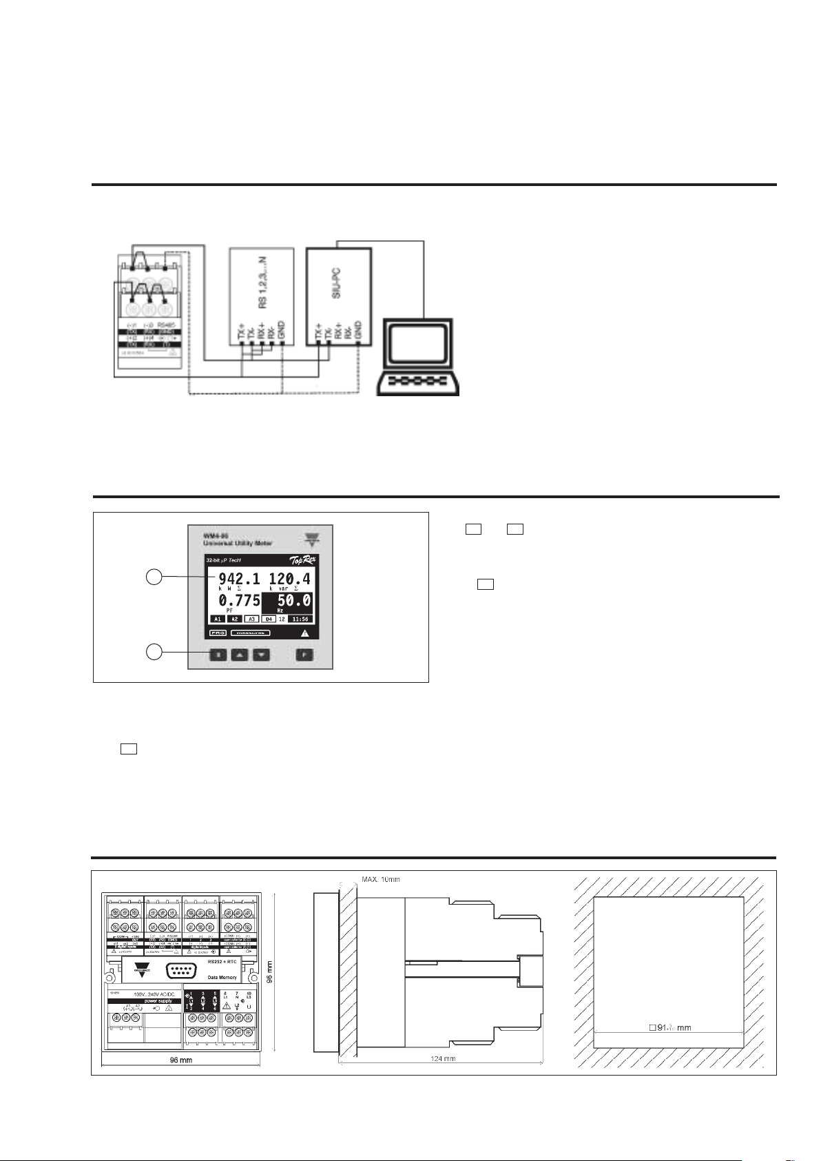
AR1034 RS422/485 4-wir
tional devices pr
RS 1, 2, 3...N) are connected in parallel.
The termination of the serial output is carried out
only on the last instrument of the network, by
means of a jumper between (Rx+) and (T).
ovided with RS422/485 (that is
es connection:
addi
-
Page 13
WM4-96
Wiring diagrams optional modules, cont.
AR1034 RS422/485 2-wires connection: additional devices provided with RS422/485 (that is
S 1, 2, 3...N) are connected in parallel.
R
The termination of the serial output is carried out
only on the last instrument of the network, by
means of a jumper between (Rx+) and (T).
ont panel description
Fr
2
1
1. Key-pad
Set-up, programming and display parameters are easily
controlled by the 4 push-buttons.
S
- to enter programming and to confirm password.
Dimensions
and
F
▼
▼
▲
▲
- to pr ogram values
- to select functions
- to scroll display pages
- for special functions
2. Display
Istantaneous measurements:
- 4 digits (max display 9999)
Energies, gas, water:
- 9 digits (max display 999999999).
Alphanumeric indications by means of LCD display for:
- Display of configuration parameters
- All measuring variables.
13
Page 14
M4-96
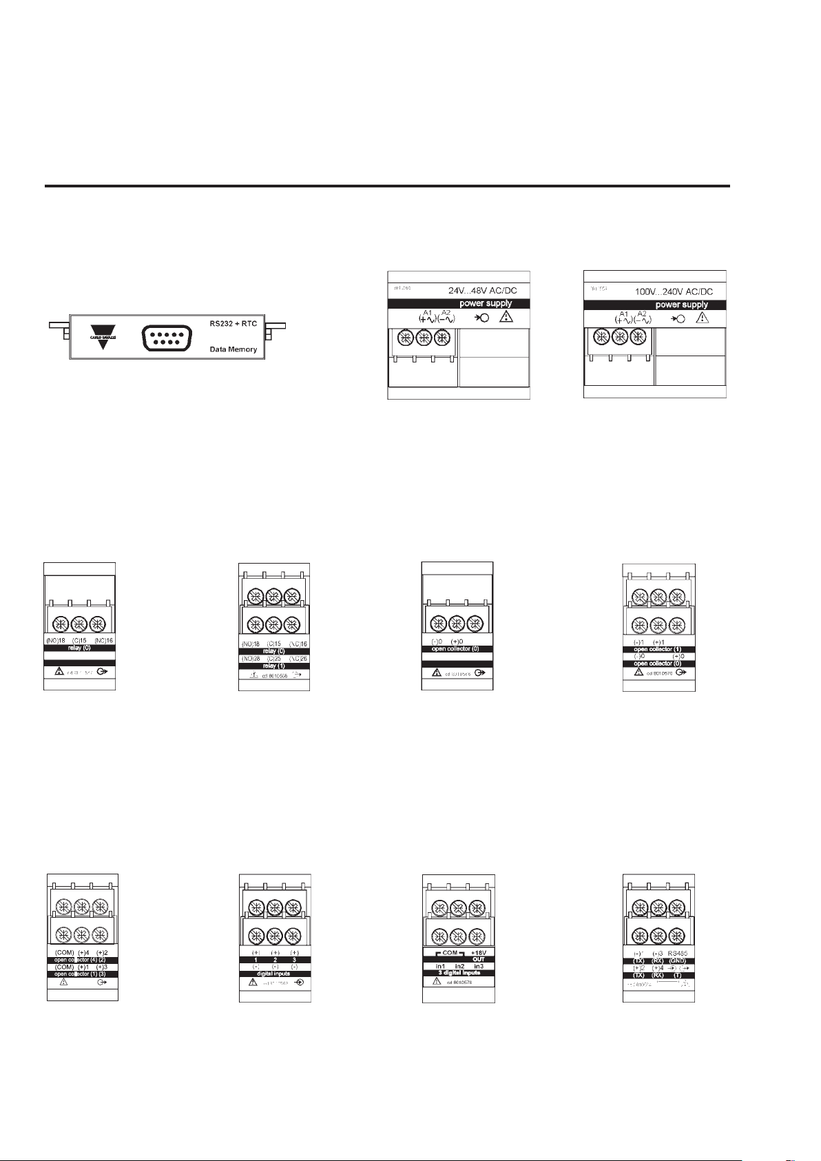
W
Modules
AR1041
RS232 Interface + RTC+ 2Mb
Data memory
Power supply modules
AP1021
Power supply 18-60VAC/DC
AP1020
Power supply 90-260 VAC/DC
Digital output modules
AO1058
Single relay output
Digital output modules
AO1035
Dual relay output
Other input/output modules
AO1059
Single open
collector output
AO1036
Dual open
collector output
AO1037
4 open collector
outputs
14
AQ1038
3 digital inputs
AQ1042
3 digital inputs + aux
AR1034
RS485 port
 Loading...