

Page 1
Energy Management
Power Analyzers
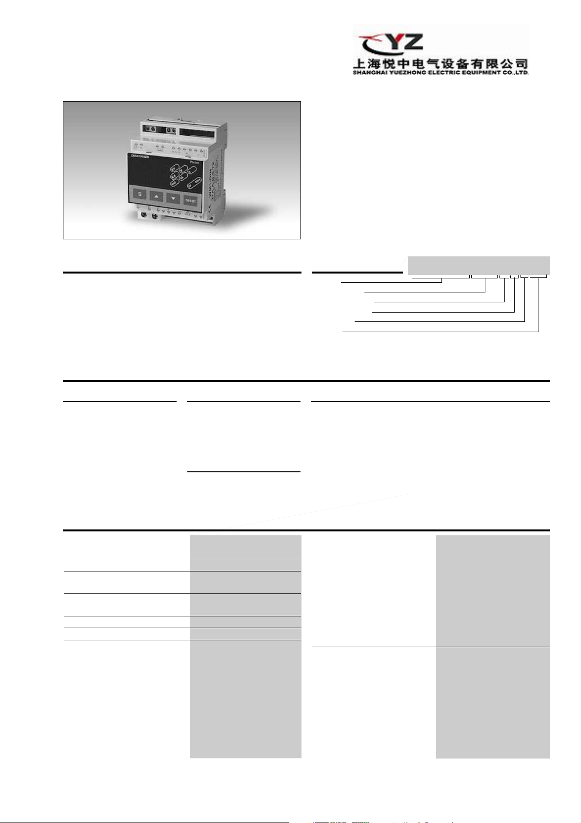
Type WM1-DIN
• 3-dgt multi-range µP-based meter
• Scrolling of power, energy,
power factor (cos ϕ), current and voltage
• Automatic selection of k (kilo) or M (mega) scale
• Automatic measurement of peak value
• Double measuring input: Up to 5 A or up to 27 A
• Degree of protection (front): IP 40
• Options: - Programable alarm setpoint output
- Pulse output for connection to remote
display or PLC
- Serial RS 485 output for connection to a
personal computer
Product Description
3-dgt µP-based meter for
measuring power, energy,
power factor (cos ϕ), current
and voltage with automatic
selection of scale. A programmable alarm setpoint
output is available on request.
The housing is easy to
mount on DIN-rail and offers
a degree of protection (front)
of IP 40.
Type Selection
Range code
27A: 5 AAC or 27 AAC
selectable
1)
on request
Power Supply
C: 115 VAC, -15% +10%,
50/60 Hz
D: 230 VAC, -15% +10%,
50/60 Hz (standard)
Set-points
0: no alarm
1: one alarm
1)
Input Specifications
Accuracy
(@ 25°C ± 5°C, R.H. ≤ 60%) ± 2 % f.s., ± 2 dgt
Temperature drift ± 250 ppm/°C,
Display 7-segment LED, h 14.2 mm,
Decimal point position Automatic selection and
Max. and min. indication Max.: 999, Min.: 0
Overflow indication “oF”
Input
Current 27 AAC permanent, direct
Voltage (48 to 62 Hz) 400 VAC (1-phase conn.)
3 digits
indication of ”k” or “M” range.
conn. max. 32 AAC for
2 minutes.
5 AAC permanent, CT conn.
max. 6 AAC for 2 minutes
500 VAC (3-phase conn.)
Ordering Key
Model
Range code
Measurement
Power supply
Setpoints
Option
Options
XX: None (1-phase/
3-phase system with
neutral, balanced load)
TX: Measurement on
3-phase system without neutral (balanced
load)
PX: Pulse output (available
only without alarm)
Input (cont.)
Type 1-phase/3-phase with neu-
Wave form Undistorted sine wave
Impedance
Voltmeter input: ≥ 1 MΩ
Ammeter input: 1 mΩ (27 A)
Key-pad enable input By means of external, volta-
WM1-DIN27A A D0XX
RX: RS 485 serial interface
(1-phase/3-phase
system, with neutral
and balanced load)
SX: RS 485 serial interface
(3-phase system, without neutral and with
balanced load)
tral, balanced load (standard)
3-phase without neutral,
balanced load (on request)
(form factor 1.11)
6 mΩ (5 A)
ge free NC contact. The input is not insulated from the
measuring inputs.
Can be used to avoid unwanted programming modifications, resets and totalized
energy.
1
Page 2
WM1-DIN
Input Specifications (cont.)
Measurements
Voltage, current,
, or V
instantaneous power V
L-N
, I, W, VA, VAR
L-L
(max. display: 999M-)
Peak value Accessible by means of the
key-pad in run mode.
Energy Wh, VAh VARh
(max. display: 999 M-)
Power factor - cos ϕ Accuracy: ± 4 dgt @ 25˚C,
voltage ≥ 3% f.s.
current ≥ 10% f.s.
Display: L.10/1.00/C.10;
In case of voltage and/or
current lower than 3% f.s.,
the display flashes “1.00”
Reset date updating Month and day of the last
reset manually programmed
by key-pad
Primary range Transformer ratio program-
mable from 1 to 999
(max. 5000/5A).
Output Specifications
General Specifications
Operating temperature 0° to 50°C (32° to 122°F)
(R.H. < 90% non-condensing)
Storage temperature -10° to 60°C (14° to 140°F)
Insulation reference voltage 300 V
Dielectric strength 4000 V
EMC EN 50081-1, EN 50082-1
Safety standards EN 61010-1, IEC 61010-1,
Connector Screw-type
Housing
Dimensions 89 x 71.5 x 58.5 mm
Material ABS,
Degree of protection IP 40 (front)
Weight Approx 320 g
Approvals CE
(R.H. < 90% non-condensing)
to ground
rms
rms
for 1 minute
VDE 0411
(4 DIN-modules)
self-extinguishing: UL 94 V-0
Alarms (on request)
Number of setpoints 0 standard (1 on request).
Setpoint adjustment From 0 to 999 MW/MVA/
MVAR/instantaneous power,
MWh/MVAh/MVARh
energy and from L/C. 10 to
1.00 cos ϕ key-pad program-
mable
Accuracy ± 2%
Hysteresis 0 to 100% f.s.
key-pad programable
Time delay adjustment 0 to 255 s
key-pad programable
Alarm type Low or high
key-pad programable
Output type Static by TRIAC. (24 VAC to
250 VAC/max. 50 mA).
Insulation 2 kV between alarm output
and all inputs and serial out -
put (if available)
Pulse output (on request)
Type
Insulated, open collector: V
= 0.6 VDC/max. 4 mA
ON
max. 20 VDC
V
OFF
Pulse: ON status 200 ms
OFF status 800 ms min.-
NPN output
Pulse number From 1 to 999 pulses for
kWh, kVAh or kVARh
Insulation 2 kV between output and
all inputs and serial output if
available
Serial output (on request)
Type One-way multidrop RS 485
(double direction: only for
standard static TRIAC output)
Addresses 256 adresses
key-pad selectable.
Data W, VA, VAR, Wh, VAh, VARh,
V, I, cos ϕ and setpoint status
where present
Data format 1 start bit - 7 data bit -
even parity - 1 stop bit.
1 start bit - 7 data bit odd parity - 1 stop bit.
1 start bit - 8 data bit no parity - 1 stop bit
Baud-rate 1200, 2400, 4800 and 9600
bauds, key-pad selectable
Connections 2 wires (max. length: 1200 m)
+ shield.
Bias and/or line termination
(selectable by DIP-switch).
Power supply Separate 5 VDC, power
consumption 70 mA (PSUDIN module).
Insulation By means of optocouplers,
2 kV between serial output
and measuring inputs.
2 kV between 5 VDC power
supply input and measuring
inputs.
2
Page 3
WM1-DIN
V
AR
V
A
M
/A
K/V
W
h
P
F
reset
S
cosϕ
71.5
89
49.5
58.5
45
46
72.5
Supply Specifications
AC supply 230 VAC, -15%+10%,
50/60 Hz (standard),
115 VAC, -15%+10%,
50/60 Hz (on request)
Insulation 4 kV between measuring
inputs and power supply
input
4 kV between enable input
and power supply input
Power consumption 2.5 VA
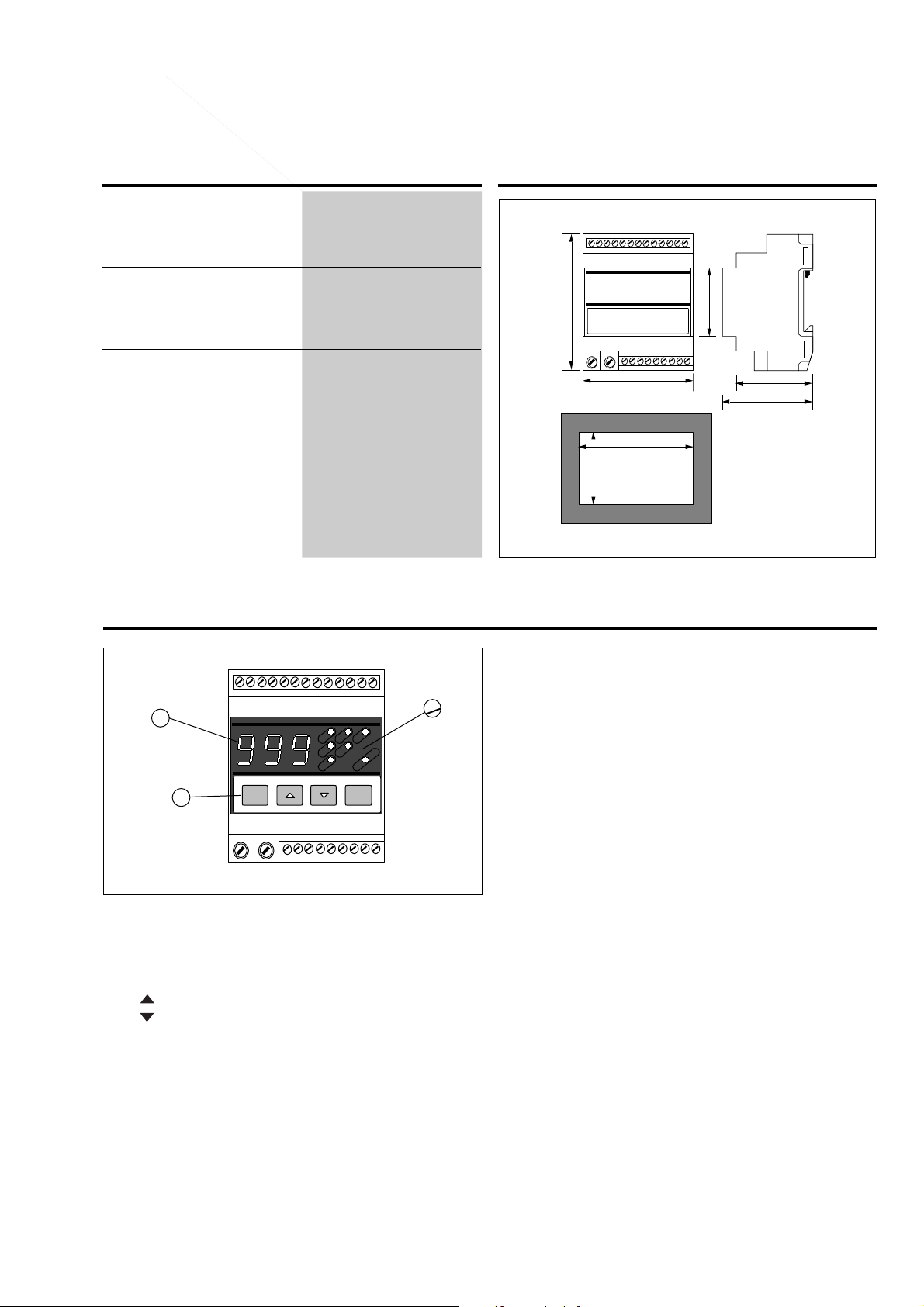
Front Panel Description
Dimensions (mm)
2
1
1. Key-pad
« S » Set/enter
« » Up
« » Down
« Reset » Special function
Set-up and programming procedures are easily controlled
by the 4 pushbuttons.
1. Key-pad (cont.)
“S”
- To enter programming.
3
“UP/DOWN” (into the programming procedure)
- To select: priority measurement, serial interface parameters or pulse output parameters (on request),
maximum power, energy or cos ϕ (on request).
“UP/DOWN” (during measurement)
- Scrolling all the available measurements
“Reset”
- Reset the displayed value (totalized energy or peak
value).
2. Display
3-digit (maximum read-out 999).
Alphanumeric indication by means of 7-segment display
for:
- Displaying of the measured value.
- Indication of programming parameters.
3. LED
To display the selected engineering unit (flashing LED to
notify an alarm activation).
3
Page 4
WM1-DIN
0
~
230V
115V
~
COM
IN 27A
11 12 13 14 15 16 17
18 19
10987654321
ENABLE
IN V
IN 5A
IN V
ALARM/
PULSE
OUTPUT
IN 5VDC RX TX
~
~
~
~
~
3
L (R/L1, S/L2, T/L3)
N
POWER
LOAD
(#)
(°) (*)
(◊)
POWER
0
~
230V
115V
~
COM
IN 27A
11 12 13 14 15 16 17
18 19
10987654321
ENABLE
IN V
IN 5A
IN V
ALARM/
PULSE
OUTPUT
IN 5VDC RX TX
~
~
~
~
~
3
L (R/L1, S/L2, T/L3)
N
LOAD
(#)
(°)
(*)
0
~
230V
115V
~
COM
IN 27A
11 12 13 14 15 16 17
18 19
10987654321
ENABLE
IN V
IN 5A
IN V
ALARM/
PULSE
OUTPUT
IN 5VDC RX TX
~
~
~
~
~
3
POWER
LOAD
(#)
(°)
(*)
R/L1
S/L2
T/L3
(◊)
0
~
230V
115V
~
COM
IN 27A
11 12 13 14 15 16 17
18 19
10987654321
ENABLE
IN V
IN 5A
IN V
ALARM/
PULSE
OUTPUT
IN 5VDC RX TX
~
~
~
~
~
3
POWER
LOAD
(#)
(°)
(*)
R/L1
S/L2
T/L3
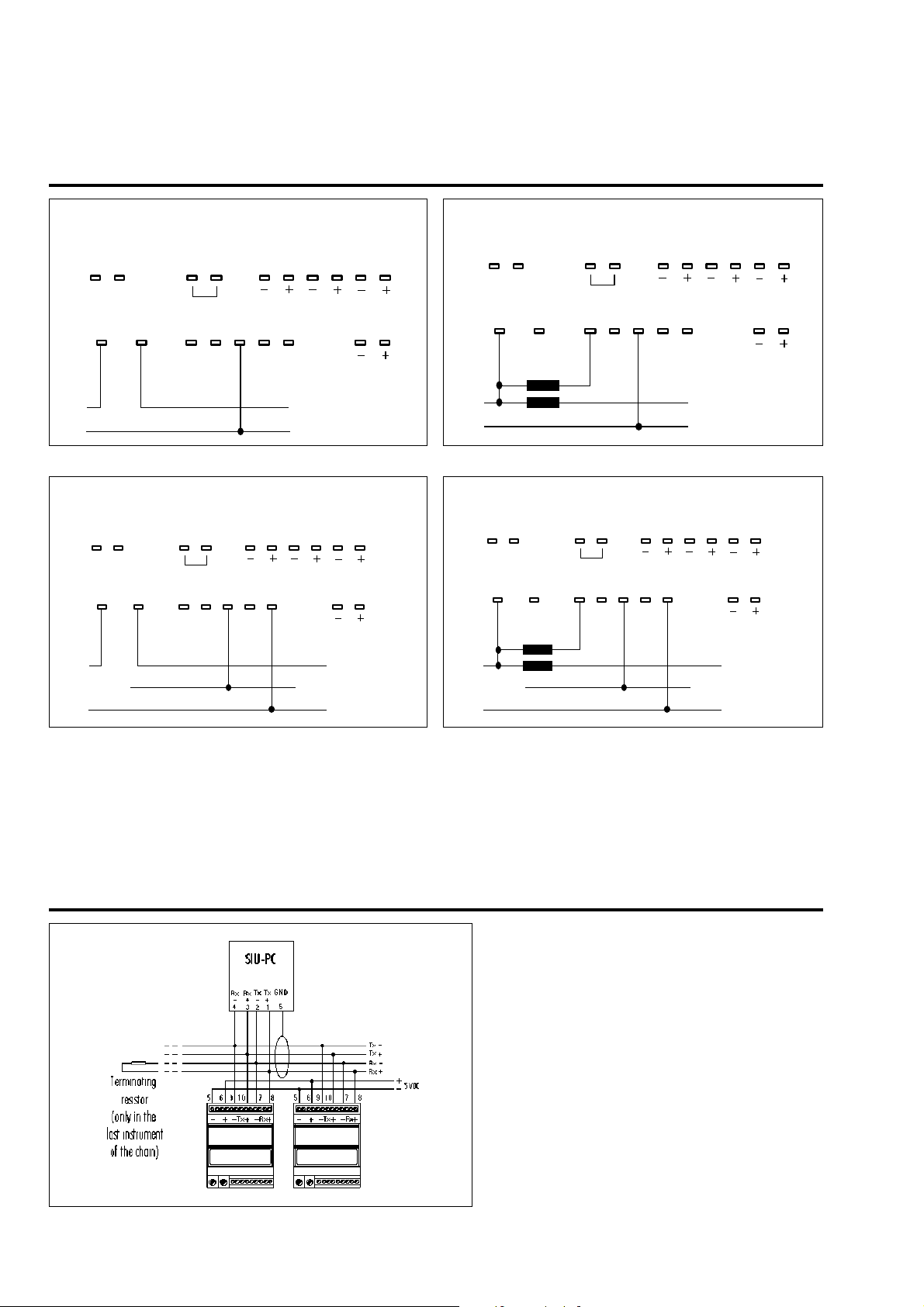
Wiring Diagrams
Direct connection on single phase or three-phase system
with neutral and balanced load
Direct connection on three-phase system without neutral
and with balanced load
CT connection on single phase or three-phase system with
neutral and balanced load
CT connection on three-phase system without neutral and
with balanced load
(*) An external 5 VDC power supply must be connected to
the RS485 serial interface output (see PSU-DIN module)
(◊) Attention: CT’s cannot be earthed
(•) Attention: The ENABLE input (KEY-PAD enabling) is not
insulated from the measuring inputs
(#) The static ALARM OUTPUT must be connected in series
to the load to be controlled, as if it were a simple contact
Network Connection
PC/WM1-DIN network connections
(RS485 interface)
4
From PSU-DIN module)
 Loading...