

Page 1
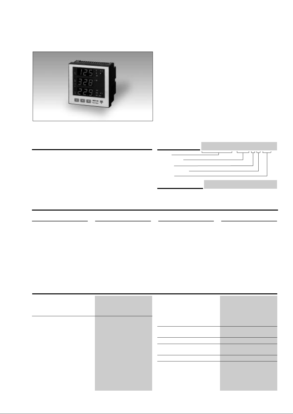
Power analyzers and Energy Meters
Power Analyzer
Type WM14-96 “Basic Version”
• Class 1 (active energy)
• Class 2 (reactive energy)
• Accuracy ±0.5 F.S. (current/voltage)
• Power analyzer
isplay of instantaneous variables: 3x3 digit
• D
• Display of energies: 8+1 digit
ystem variables and phase measurements: W, W
• S
ar, VA, VA
v
, A
• A
max
• Energy measurements: kWh and kvarh
• Hour counter (5+2 DGT)
• TRMS meas. of distorted sine waves (voltages/currents)
• Power supply: 24V, 48V, 115V, 230V, 50-60Hz; 18 to 60VDC
• Optional dual pulse output
• Alarms (visual only) VLN, An
• Optional galvanically insulated measuring inputs
• Protection degree (front): IP65
• Front dimensions: 96x96mm
• Optional RS422/485 serial port
dmd max
PF, V, A, An, A
,
dmd
, W
dmd max
dmd
indication
,
Hz
,
dmd
Product Description
3-phase power analyzer with
built-in programming keypad. Particularly recommended for displaying the
main electrical variables.
Housing for panel mounting,
(front) protection degree
IP65, and optional RS485
serial port or dual pulse output. Parameters programmable by means of
CptBSoft.
How to order
Model
Range code
System
Power supply
Option
How to order
CptBSoft (compatible only with S or SG options): software
to program the working parameters of the power analyzer
Type Selection
Range codes
AV5: 380/660V
VL-N: 185 V to 460 V
VL-L: 320 V to 800 V
AV6: 120/208V
VL-N: 45 V to 145 V
VL-L: 78 V to 250 V
Phase curr
Neutral current: 0.09 to 6A
ent: 0.03A to 6A
/5(6)AAC
-L
L
/5(6)AAC
L-L
System
3 : 1-2-3-phase,
balanced/unbalanced
load,with or without
neutral
and to read the energy and the instantaneous variables.
Power supply
A:
B: 48V
C: 115VAC
D: 230VAC
3: 18 to 60VDC (not
Input specifications
Rated inputs
Current “X-S options” 3 (non insulated each other)
Curren t “SG-PG options” 3 (insulated each other)
Voltage 4
Accuracy
(@25°C ±5°C, R.H. ≤60%) 1150W-VA-var, FS:230VLN,
Current 0.25 to 6A: ±(0.5% FS +1DGT)
Neutral curr
Phase-phase voltage
Phase-neutral voltage
Active and Appar
Reactive power 0.25 to 6A: ±(2% FS +1DGT);
(dis play, RS 4 85) with CT=1 and VT=1 AV5:
400VLL; AV6: 285W-VA-var,
FS:57VLN, 100VLL
ent
ent power
0.03A to 0.25A: ±(0.5%FS+7DGT)
0.25 to 6A:
0.09A to 0.25A:
±(1.5%
(0.5%
±
0.25 to 6A:
,
0.03A to 0.25A:
+5DGT)
(1.5% FS +1DGT)
±
FS +1 DGT)
FS
±(1% FS +1DGT);
+ 1
(0.5%
±
FS+7DGT)
)
DGT
±(1% FS
Additional errors
T
Sampling rate 1400 samples/s @ 50Hz
Display r
Display
WM14-96 AV5 3 D PGX
CptBSoft
Options
24VAC
-15+10%, 50-60Hz
AC
-15+10%, 50-60Hz
-15+10%, 50-60Hz
-15+10%, 50-60Hz
available in case of
SG or PG options)
Active ener
Reactive ener
Active energy “SG-PG opt.” Cl a s s 1 ( s t a r t u p “I”:3 0 m A )
Reactive energy “SG-PG opt.”
Frequency ±0.1Hz (48 to 62Hz)
Humidity
emperature drift
Type LED, 14mm
Read-out for instant. var. 3x3 DGT
Read-out for ener
gy “X-S option”
gy “X-S option” Class 3 (start up “I”: 30mA)
esh time
efr
gies
X:
None
S:
RS485 port
SG:
RS485+galvanic insulated measurig inputs
PG:
Dual pulse output +
galvanically insulated
measuring inputs.
0.03A to 0.25A: ±(2% FS +5DGT)
Class 2 (start up
Class 2 (start up “I”:
0.3% FS, 60% to 90% RH
≤
200ppm/
≤
1700 samples/s @ 60Hz
700ms
3+3+3 DGT (Max indication:
999 999 99.9)
C
°
“I”: 30mA)
30mA)
1
Page 2
WM14-96
Input specifications (cont.)
isplay (cont.)
D
ead-out for hour counter 1+3+3 D G T ( M a x. i n d i c a t i o n :
R
999 9.99)
9
Measurements Current, voltage, power,
power factor , fr equency,
energy , TRMS measur ement
of distorted waves.
Coupling type Direct
Crest factor < 3, max 10A peak
Input impedance (X-S options)
380/660V
(A V5) 1 MΩ ±5%
L-L
RS485 Serial Port Specifications
20/208V
1
V6) 453 K
(A
-L
L
Ω ±
5%
Current ≤ 0.02Ω
Input impedance (PG-SG options)
380/660V
120/208V
(A V5) 1 MΩ ±1%
-L
L
(A V6) 1 MΩ ±1%
L-L
Current ≤ 0.02Ω
Frequency 48 to 62 Hz
verload protection
O
ontinuos voltage/current 1.2 F.S.
C
For 500ms: voltge/current 2 Un/36A
RS422/RS485 (on request)
Type Multidrop
bidirectional (static and
dynamic variables)
Connections 2 or 4 wires, max. distance
1200m, termination directly
on the instrument
Data (bidirectional)
Dynamic (reading only) System, phase variables and
energies
Static (writing only) All configuration parameters
Data format 1 bit di start , 8 data bit,
no parity, 1 stop bit
Baud-rate 9600 bit/s
Addresses 1to 255, key-pad selectable
Protocol MODBUS/JBUS
CptBSoft software: parameter programming and reading data
CptBSoft Multi language software to
program the working
parameters of the power
analyzer and to read the
energies and the
instantaneous variables.
The program runs under
Windows 95/98/98SE/2000/
Working mode T wo dif ferent working
Data access By means of RS485
NT/XP.
modes can be selected:
- management of a local
RS485 network;
- management of
communication from a single
instrument to PC (RS232);
serial port.
Dual pulse output
Digital outputs (on request)
Pulse outputs
Number of outputs
Number of pulses
Output type
2
(one for kWh one for kvarh)
2
om 0.01 to 999 in
Fr
compliance with the
following formula:
[
Psys max (kW or
kvar)*pulses (pulses/kWh
or kvarh)]
<14400
Relay
ent: 0.05A@250V
min curr
max curr
ent: 5A@250V
AC/30VDC
AC/30VDC
Electrical life: min 2*10
6
Pulse duration
Mechanial life: 5*10
100ms <120ms (ON)
≥
100ms (OFF)
≥
According to EN622053-31
Insulation By means of relays,
4000 V
outputs to
RMS
measuring inputs,
4000 V
output to
RMS
supply input.
Insulation between the two
outputs: 1000V
RMS
5
cycles
cycles
Page 3
WM14-96
Software functions
assword
P
1st level Password “0”, no
2nd level Password from 1 to 999,
ystem selection
S
Transformer ratio
CT 1 to 999
VT 1.0 to 99.9
Filter
Operating range 0 to 100% of the input
Filtering coefficient 1 to 16
Filter action Measurements, alarms,
Displaying Up to 3 variables per page
3-phase system with neutral
umeric code of max. 3
N
digits; 2 protection levels
f the programming data
o
protection
all data are protected
-phase with/without n, unbal.
3
-phase balanced
3
-phase ARON, unbalanced
3
2-phase
Single phase
display scale
serial out. (fundamental var: V ,
A, W and their derived ones).
Page 1:
Page 2: V L12, V L23, V L31
Page 3:
Page 4:
V L1, V L2, V L3
A L1, A L2, A L3
A L1 dmd, A L2 dmd,
A L3 dmd
age 5: An, An Alarm
P
Page 6: W L1, W L2, W L3
age 7: PF L1, PF L2, PF L3
P
Page 8: var L1, var L2, var L3
Page 9: VA L1, V A L2, V A L3
Page 10: VA ∑, W ∑,var ∑
Page 11: VA dmd, W dmd, Hz
Page 12: W dmd max (*)
Page 13: Wh (*)
Page 14: varh (*)
Page 15: VL-L ∑, PF ∑,
Page 16: A max (*)
Page 17: A dmd max (*)
Page 18: hour counter
(*) = These variables are
stored in EEPROM when the
instrument is switched off
Alarms Programmable, for the VL∑and
An (neutral current).
Note: the alarm is only visual,
by means of LED on the front
of the instrument.
Reset Independent
alarm (VL∑,An)
max: A dmd, W dmd
all energies (Wh, varh) and
hour counter
VLN Alarm
(*)
Power Supply Specifications
Auxiliary power supply 230VAC
-15 +10%, 50-60Hz
115VAC
-15 +10%, 50-60Hz
48VAC
-15 +10%, 50-60Hz
General Specifications
Operating 0° to +50°C (32 to 122°F)
temperature
Storage -10° to +60°C (14 to 140°F)
temperature
Installation category Cat. III (IEC 60664, EN60664)
Insulation (for 1 minute) 4000
(RH < 90% non condensing)
(RH < 90% non condensing)
VAC, 500VDC
between mesuring
inputs and power supply.
500VAC/DC between
24VAC
-15 +10%, 50-60Hz
18 to 60VDC
Power consumption AC: 4.5 VA
DC: 4W
mesuring inputs and RS485.
4000VAC, 500VDC between
power supply and RS485
Dielectric strength 4000 V AC (for 1 min)
EMC
Emissions EN50084-1 (class A)
residential environment,
commerce and light industry
3
Page 4
WM14-96
General Specifications (cont.)
EMC (cont.)
Immunity EN61000-6-2 (class A)
industrial environment.
ulse voltage (1.2/50µs)
P
N61000-4-5
E
Safety standards IEC60664, EN60664
Approvals CE, (cURus, CSA only “X”
nd “S” options)
a
Connections 5(6) A Screw-type
Max cable cross sect. area 2.5 mm
2
ousing
H
Dimensions (WxHxD) 96 x 96 x 63 mm
Material ABS
self-extinguishing: UL 94 V-0
Mounting Panel
Protection degree Front: IP65 (standard),
NEMA4x, NEMA12
Connections: IP20
W
eight
ox. 400 g (pack. incl.)
Appr
Display pages
Display variables in 3-phase systems (in a 3-phase system with neutral)
No 1stvariable 2ndvariable 3rdvariable Note
1 V L1 V L2 V L3
2 V L12 V L23 V L31 Decimal point blinking on the right
of the display
3 A L1 A L2 A L3
4 A L1 dmd A L2 dmd A L3 dmd dmd = demand (integration time
5 An AL.n AL.n if neutral current alarm is
6 W L1 W L2 W L3 Decimal point blinking on the right
7 PF L1 PF L2 PF L3
8 var L1 var L2 var L3 Decimal point blinking on the right
9 VA L1 VA L2 VA L3
10 VA system W system var system
11 VA dmd W dmd Hz dmd = demand (integration time
(system) (system) (system) selectable from 1 to 30 minutes)
12 W dmd MAX Maximum sys power demand
13 Wh (MSD) Wh Wh (LSD) The total indication is given in
14 varh (MSD) varh varh (LSD) The total indication is given in
15 V LL system AL.U PF system AL.U= is activated only if one of
16 A MAX
17 A dmd max max. dmd current among the three phases
18 h hour counter
selectable from 1 to 30 minutes)
active
of the display if generated power
of the display if generated power
max 3 groups of 3 digits.
max 3 groups of 3 digits.
VLN is not within the set limits.
max. current among the three phases
MSD: most significant digit
LSD: least significant digit
V
L
1
L
2
h
L
3
k
M
A
VA
W
var
al
Hz
dmd
PF
4
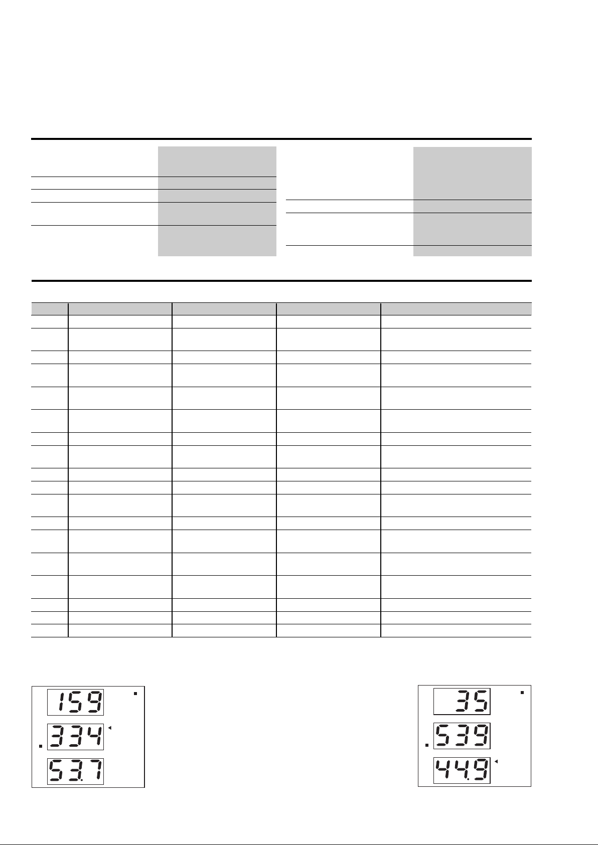
1) Example of kWh visualization:
This example is showing 15 933 453.7 kWh
2) Example of kvarh visualization:
This example is showing 3 553 944.9 kvarh
V
L
1
L
2
h
L
3
k
M
A
VA
W
var
al
Hz
dmd
PF
Page 5
WM14-96
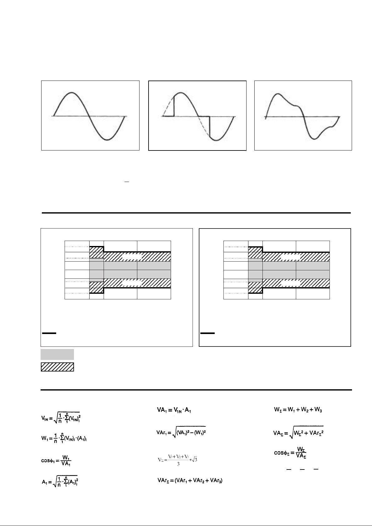
Waveform of the signals that can be measured
igure A
F
Sine wave, undistorted
Fundamental content 100%
Harmonic content 0%
A
= 1.1107 | A |
ms
r
Figure B
Sine wave, indented
Fundamental content 10...100%
Harmonic content 0...90%
Frequency spectrum: 3rd to 16th harmonic
Additional error: <1% FS
Accuracy
kWh, accuracy (RDG) depending on the current
PF=1 PF=L0.5
+2.5%
+2%
+1.5%
+1%
0%
+1%
+1.5%
+2%
+2.5%
PF=L0.5
or C0.8
Error
Class 2
Class 1
Class 2
PF=1
0.10A
(0.02In)
0.25A
(0.05In)
0.25A
(0.05In)
0.5A
(0.1In)
5A (In)
5A (In)
Class 2 accuracy limits (Active energy)
5(6A) Start-up current: 30mA
6A (Imax)
6A (Imax)
or C0.8
+1.5%
+ 1%
- 1%
-1.5%
Figure C
Sine wave, distorted
Fundamental content 70...90%
Harmonic content 10...30%
Frequency spectrum: 3rd to 16th harmonic
Additional error: <0.5% FS
kvarh, accuracy (RDG) depending on the current
Error
+4%
+3%
+2.5%
+2%
0%
+2%
+2.5%
+3%
+4%
sin
ϕ=0.5
sin
ϕ=1
0.1A
(0.02In)
0.25A
(0.05In)
0.25A
(0.05In)
0.5A
(0.1In)
Class 3
Class 2
Class 3
5A (In)
5A (In)
Class 3 accuracy limits (Reactive energy)
5(6A) Start-up current: 30mA
6A (Imax)
6A (Imax)
: this graph is only referred to instrument models with the “SG or PG” option.
: this graph is only referr
ed to instrument models with the “X or S” option.
Used calculation formulas
Phase variables
Instantaneous effective voltage
Instantaneous active power
Instantaneous power factor
Instantaneous effective current
Instantaneous apparent power
Instantaneous r
eactive power
System variables
Equivalent 3-phase voltage
3-phase reactive power
3-phase active power
3-phase apparent power
3-phase power factor
Neutral current
A
An =
A
A
+
+
L1
L2
L3
5
Page 6
WM14-96
Used calculation formulas (cont.)
nergy metering
E
Where:
= considered phase (L1, L2 or L3)
i
P = active power
Q = reactive power
t
t
starting and ending time points of consumption recording
,
=
1
2
n = time unit
∆t= time interval between two successive power consumptions
n
=starting and ending discrete time points of consumption recording
1,n2
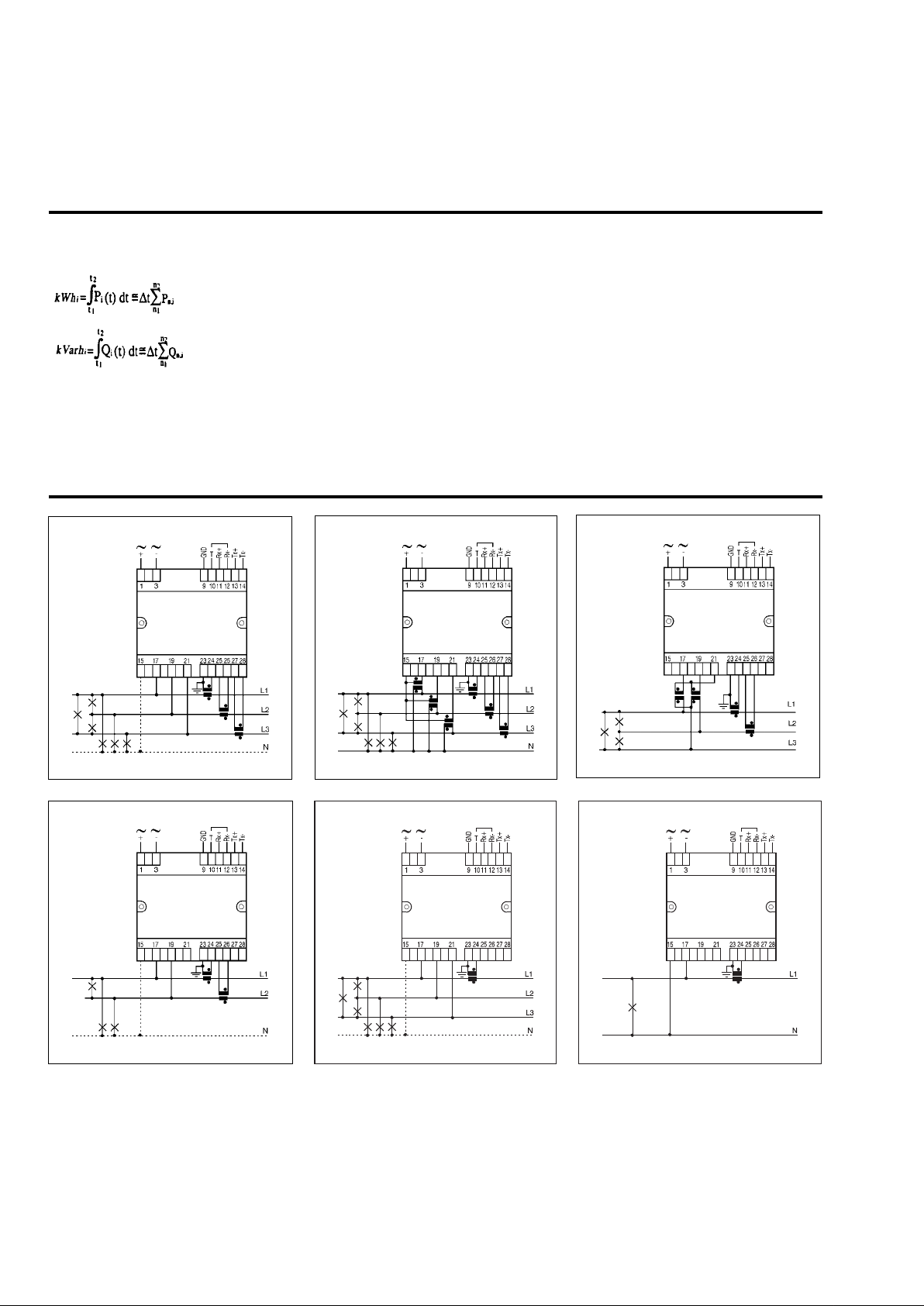
Wiring diagrams
Fig. 1
Fig. 4
Fig. 2
3CT and 3VT connectionCT connection
Fig. 5
ARON and VT connection
Fig. 3
Fig. 6
2-phase connection 3-phase load balanced connection
1-phase connection
NOTE: Only for “PG” and “SG” options: the current measuring inputs are galvanically insulated
and therefore they can be connected to ground singly.
NOTE: For all models except for “PG” or “SG” the current inputs can be connected to the lines
ONLY by means of current transformers. The direct connection is not allowed.
6
Page 7
WM14-96
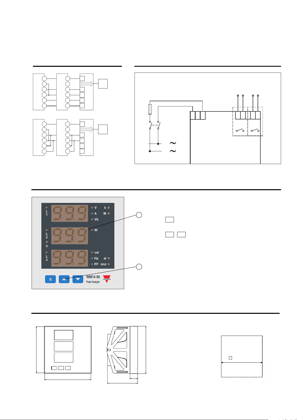
RS485 port connections
a] [b] [c]
[
ND
GND
T
10
11
RX+
12
RX-
1
X+
T
14
TX-
[a] [b] [c]
GND
T
10
11
X+
R
12
RX-
13
TX+
14
X-
T
GND
9
3
9
T
RX+
RX-
X+
T
TX-
GND
T
X+
R
RX-
TX+
X-
T
9
10
11
12
13
1
4
9
10
11
12
13
14
Fig. 7: a-Last instrument; b-1...n Instrument
c-RS485/232 serial converter
ont Panel Description
Fr
G
RS485RS232
TX+
X-
T
X+
R
X-
R
ND
G
RS485RS232
X+
T
TX-
RX+
RX-
PC
-wire
4
connection
PC
2-wire
connection
Dual pulse output connections
1 3 11 12 1314
3
1
N
1. Key-pad
2
+
L
-
To program the configuration parameters and the display of
the variables.
S
Key to enter programming and confirm selections;
▲▲
▲▲
Keys to:
- programme values;
- select functions;
- display measuring pages.
Fig. 8
Pulse1
6
7
Pulse2
8
9
Dimensions and Panel Cut-out
96mm
96mm
61.4mm
1
15.4mm
2. Display
LED-type with alphanumeric indications to:
- display configuration parameters;
- display all the measured variables.
96mm
91mm
7
 Loading...