

Page 1

W90210F
W90210F
PA-RISC Embedded Controller
1 Version 1.4, 10/8/97
The above information is the exclusive intellectual property of Winbond Electronics Corp. and shall not be disclosed, distributed or reproduced without permission from Winbond.
Page 2

W90210F
Table of Contents
TABLE OF CONTENTS 2
1. GENERAL DESCRIPTION 5
2. FEATURES 6
3. W90210F 208-PIN PQFP PIN CONFIGURATION 7
4. W90210F PIN DESCRIPTION 8
5. W90210F CPU CORE 12
5.1 Architecture 12
5.1.1 PA-RISC Rev. 1.1 third edition 12
5.1.2 Level 0 implementation 12
5.1.3 Multimedia Extension Instruction Set 12
5.2 CPU resources 12
5.2.1 General registers 12
5.2.2 Shadow registers 13
5.2.3 Processor Status Word (PSW) 13
5.2.4 Control registers 14
5.2.5 W90210F External Interrupt Request register (EIRR; CR23) 15
5.2.6 AIRs (Architecture Invisible Registers) 15
5.3 Implementation of the PA-RISC instructions 15
5.3.1 Implementation of Level 0 instructions 16
5.3.2 Implementation of cache-related instructions 16
5.3.3 PA-RISC multimedia extension instruction set 17
5.3.4 DIAG instruction 17
5.4. Debug Special Function Unit 19
5.5 Addressing and access control 20
5.5.1 Memory and I/O space 20
5.5.2 RESET addresses 20
5.5.3 Access control 20
5.6 Interruptions 21
6. PIPELINE ARCHITECTURE 22
2 Version 1.4, 10/8/97
The above information is the exclusive intellectual property of Winbond Electronics Corp. and shall not be disclosed, distributed or reproduced without permission from Winbond.
Page 3

W90210F
6.1 Branch prediction 22
6.2 Load use interlock 23
7. ON-CHIP CACHE MEMORIES 24
7.1 Instruction cache 24
7.2 Data cache 24
7.2.1 Write-through Cache Support 25
7.3 Non-cacheable address space 25
8. MEGACELLS DESCRIPTION 26
8.1 DRAM Controller & ROM Controller 26
8.1.1 DRAM controller 26
8.1.2 ROM controller 27
8.1.3 Memory controller registers 27
8.2 DMA Controller (DMAC) 30
8.2.1 Register Description: 30
8.3 Timer / Counter 32
8.4 Serial I/O 33
8.4.1 UART Register Definition 33
8.5 Parallel Port 36
8.5.1 ECP Register Description 36
9. TIMING DIAGRAM 39
9.1 Memory controller 39
9.1.1 DRAM AC Timimg 39
9.1.2 ROM AC Timimg 39
9.2 DMA Controller 41
9.2.1 DMA device register read timing 41
9.2.2 DMA device register write timing 42
9.2.3 DMA demand mode data read cycles 43
9.2.4 DMA demand mode data write cycles 44
9.2.5 DMA block mode data read cycles 45
9.2.6 DMA block mode data write cycles 46
APPENDIX A. PA-RISC MULTIMEDIA INSTRUCTION SET 48
APPENDIX B. DIAGNOSTIC INSTRUCTIONS 53
3 Version 1.4, 10/8/97
The above information is the exclusive intellectual property of Winbond Electronics Corp. and shall not be disclosed, distributed or reproduced without permission from Winbond.
Page 4

W90210F
4 Version 1.4, 10/8/97
The above information is the exclusive intellectual property of Winbond Electronics Corp. and shall not be disclosed, distributed or reproduced without permission from Winbond.
Page 5
W90210F
1. General Description
The W90210F Embedded Controller is part of Winbond′s W90K Embedded processor family. The processor
is a high-performance, highly integrated 32-bit processor intended for a wide range of embedded applications, such as
set-top box, web browser, X-terminal, and visual/data communication devices..
The W90210F CPU core is based on the HP PA-RISC architecture and is upward code compatible with the
W90K. The PA-RISC architecture incorporates traditional RISC elements, such as instruction pipelining, a register-toregister instruction set and a large, general-purpose register file. Separate on-chip instruction and data caches allow the
W90210F to fetch an instruction and access data in a single processor cycle.
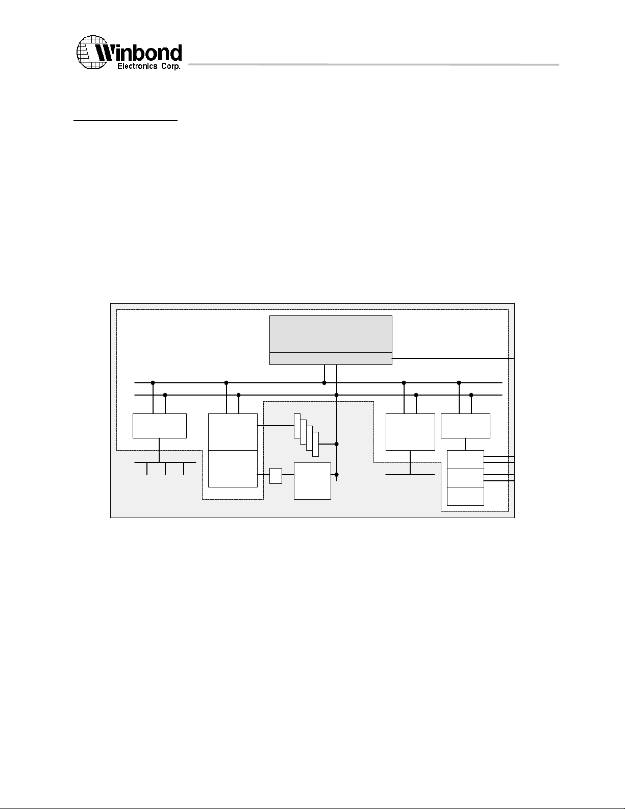
The W90210F includes several features that greatly increase performance, reduce system component count
and ease the overall system design task. In addition to its cache memories, the W90210F′s on-chip support features
include a DRAM controller, ROM/FLASH ROM interface, PCI bridge, DMA controller, two serial ports with FIFO, IEEE
1284 parallel port, timer/counters, and enhanced debug support- all features that are commonly required in embedded
applications.
Figure 1.1 shows the system diagram of W90210F.
W90K CPU core
internal bus
PCI Bridge
DRAM
Interface
ROM/
FLASH ROM
Interface
Bus Interface Unit
DRAM array
Memory
Data
Bus
8/16/32-bit
ROM
latch
Figure 1.1 W90210F System Diagram
CPU RST, CPU CLOCK
Address/Control Bus
2-Channel
DMA
Controller
8-bit DMA
I/O Bus
32-bit Data Bus
Peripheral
Bridge
Serial
Ports
ECP
Timer
5 Version 1.4, 10/8/97
The above information is the exclusive intellectual property of Winbond Electronics Corp. and shall not be disclosed, distributed or reproduced without permission from Winbond.
Page 6

W90210F
2. Features
Main features of the W90210F
• PA-RISC architecture
PA-RISC 1.1 third edition instruction set
PA-RISC level zero implementation
Support PA-RISC Multimedia Extension 1.0 instruction set
W90K binary compatible for user software
• High-performance implementation
Five-stage pipeline
Precise, efficient handling of pipeline stalls and exceptions
Delayed branch with static branch prediction
Forward: not taken
Backward: taken
One-cycle stall when prediction is wrong
HIT under miss
Both load and store can be queued when miss
Load/store single cycle execution after previous miss
• On-chip cache memory
Internal I-cache: Direct mapped, 4 KB cache (256 entries, four words/entry)
Wrap around fetching when cache miss
Cache freeze capability
Internal D-cache: 2-way set associative, 2 KB cache (2×64 entries, four words/entry)
Write-back cache with write buffer
Write-through option
New line send to CPU before dirty line write back
• Enhanced debug capability
Debug SFU supports both instruction breakpoints and data breakpoints
• High on-chip integration and simple I/O interface
486-like bus interface for CPU core
Memory controller to support four banks of DRAM and ROM/FLASH ROM
2-channel 8-bit DMA controller
PCI bridge
Two Serial ports with FIFO
Extended Capabilities Port (ECP)
Two 24-bit timer/counters
• Power Down mode
Provide power down mode for power saving operation
6 Version 1.4, 10/8/97
The above information is the exclusive intellectual property of Winbond Electronics Corp. and shall not be disclosed, distributed or reproduced without permission from Winbond.
Page 7
W90210F
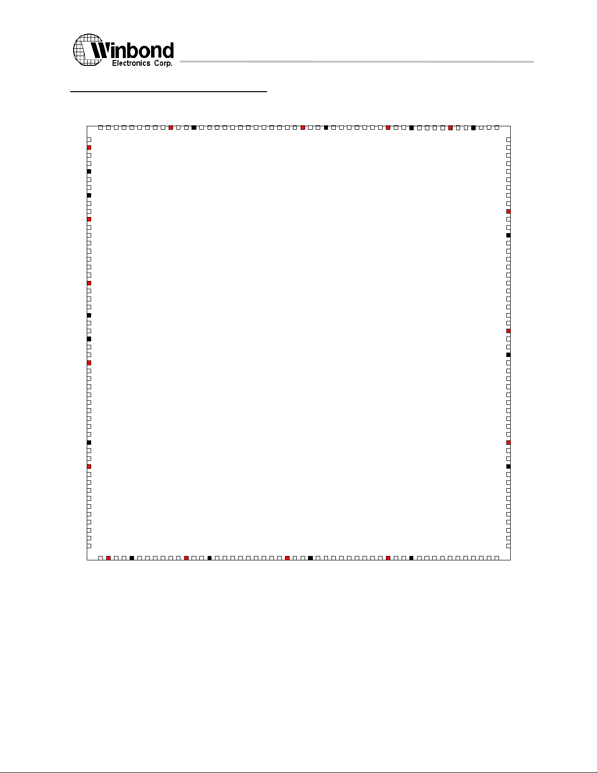
3. W90210F 208-Pin PQFP Pin Configuration
S
R
R
R
R
W
M
M
M
A
2
A
A
E
A
A
S
S
#
0
1
#
#
3
2
V
C
A
A
D
A
S
S
D
S
#
#
#
0
1
3
C
C
C
V
A
A
A
S
S
S
S
S
#
#
#
0
2
1
M
M
M
M
D
D
D
D
2
2
3
3
8
9
0
1
M
M
M
M
D
D
D
D
2
2
2
2
4
5
6
7
M
D
2
3
D
D
D
D
D
D
1
2
2
2
2
9
0
1
V
M
M
M
M
M
M
M
S
D
D
D
S
1
1
1
6
7
8
D
D
D
D
1
1
1
1
2
3
4
5
D
D
D
D
9
1
1
D
0
1
I
M
M
M
V
D
D
S
8
7
S
I
M
V
M
M
M
M
D
D
6
5
V
D
D
D
D
D
D
S
4
D
3
2
1
0
M
M
M
M
V
M
M
M
M
V
MA3
VDD
MA4
MA5
VSS
MA6
MA7
VSSI
MA8
MA9
VDDI
MA10
MA11
ROMEN
ROMRW#
ROMOE#
RCS#0
RCS#1
VDD
RCS#2
RCS#3
PCLK
VSS
RST
OSC
VSSI
RCIRST
PCICLK
VDDI
GNT0#
GNT1#
PREQ0#
PREQ1#
PDA31
PDA30
PDA29
PDA28
PDA27
VSS
PDA26
PDA25
VDD
PDA24
COMBE3
PDA23
PDA22
PDA21
PDA20
PDA19
PDA18
PDA17
PDA16
2
1
0
5
5
10
15
20
25
2
0
0
1
9
5
1
9
0
1
8
5
W90210F
1
8
0
1
7
5
1
7
0
1
6
5
208-pin PQFP
30
35
40
45
50
5
5
I
V
F
C
R
D
R
O
D
D
A
M
Y
M
B
#
E
E
#
2
6
0
T
D
V
S
P
R
E
S
T
L
D
V
S
O
O
Y
S
P
C
#
E
#
K
L
#
#
6
5
P
S
P
C
V
E
E
P
O
D
R
R
A
M
D
R
R
R
B
I
#
#
E
1
7
0
P
P
P
V
S
S
I
P
D
D
D
D
A
A
A
A
1
1
1
1
5
4
3
2
7
5
P
P
P
P
D
A
1
1
C
D
D
D
O
A
A
A
M
1
9
8
B
0
E
0
8
0
P
P
P
V
V
D
D
D
S
D
A
A
A
S
D
7
6
5
8
5
P
P
P
P
D
A
4
P
D
D
D
D
A
A
A
A
3
2
1
0
9
0
I
I
I
I
V
N
N
N
N
D
T
T
T
T
D
A
B
C
D
I
#
#
#
#
9
5
S
S
C
D
V
I
S
N
S
1
I
D
O
T
S
T
U
S
R
R
T
1
1
1
1
n
n
n
1
6
0
1
0
0
S
S
R
T
S
1
n
D
D
I
O
A
C
N
U
1
D
2
T
1
1
2
nStrobe
155
nAutoFd
nInit
nSelectIn
ED0
ED1
150
ED2
ED3
ED4
VDD
ED5
145
ED6
VSS
ED7
Select
PError
140
nACK
nFAULT
Busy
CS1
CS0
135
DACK1
DACK0
DREQ1
VDDI
DREQ0
130
DD0
VSSI
DD1
DD2
DD3
125
DD4
DD5
DD6
DD7
TC1
120
TC0
IOR
VDD
IOW
DMARDY
115
VSS
DA0
DA1
DA2
DA3
110
DA4
DA5
DA6
DA7
DA8
105
DA9
R
D
I
A
N
1
1
0
7 Version 1.4, 10/8/97
The above information is the exclusive intellectual property of Winbond Electronics Corp. and shall not be disclosed, distributed or reproduced without permission from Winbond.
Page 8

W90210F
4. W90210F Pin Description
RSTI24
CPU RESET input, high active
PCLK
I22CPU CLOCK input
OSCI25
14.318Mhz Oscillator input for Timer, UART
INTA#
INTB#
INTC#
INTD#
I87888991
PCI Interrupt input, level senstive, low active signal. Once the
INTx# signal is asserted, it remains asserted until the device driver
clear the pending request. When the request is cleared, the device
deasserts its INTx# signal.
PREQ0#
PREQ1#
I3233
PCI Request input, indicates to the PCI arbiter that this agent
desires use of the bus.
GNT0#
GNT1#
O3031
PCI Grant output, indicates to the agent that access to the bus
has been granted.
PLOCK#
I61PCI Lock signal, indicates an atomic operation that may require
multiple transactions to complete. When PLOCK# is asserted,
non-exclusive transactions may proceed to an address that is not
currently locked.
PCIRST#
O27PCI Reset output, is used to bring PCI-specific registers,
sequencers, and signals to a consistent state. Low active.
PCICLK
O28PCI Clock output, provides timing for all transactions on PCI and is
an input to every PCI device.
SERR#
I63PCI System Error is for reporting address parity errors, data parity
errors on the Special Cycle command, or any other system error
where the result will be catastrophic. The assertion of SERR# is
synchronous to the clock and meets the setup and hold times of
all bused signals.
PERR#
I/O62PCI Parity Error is only for the reporting of data parity errors during
all PCI transactions except a Special Cycle. The PERR# pin is
sustained tri-state and must be driven active by the agent receiving
data two clocks following the data when a data parity error is
detected. The minimum duration of PERR# is one clock for each
data phase that a data parity error is detected. An agent cannot
report a PERR# until it has claimed the access by asserting
DEVSEL# (for a target) and completed a data phase or is the
master of the current transaction.
PIN Name DIR PIN # DESCRIPTION
CPU Signal
PCI LOCAL BUS
for more detail description of the PCI signals please refer to the PCI LOCAL BUS
SPECIFICATION
The above information is the exclusive intellectual property of Winbond Electronics Corp. and shall not be disclosed, distributed or reproduced without permission from Winbond.
8 Version 1.4, 10/8/97
Page 9

W90210F
PDA[31:0]
tri-state
I/O
34-38, 40-41, 43,
45-52, 68-75, 78-
79, 81-86
PCI tri-state Address/Data bus, Address and Data are multiplexed
on the same PCI pins. A bus transaction consists of an address
phase followed by one or more data phases. PCI supports both
read and write bursts. The address phase is the clock cycle in
which FRAME# is asserted. During the address phase PDA[31:0]
contain a physical address. During data phases PDA[7:0] contain
the least significant byte (lsb) and PDA[31:24] contain the most
significant byte (msb). Write data is stable and valid when IRDY# is
asserted and read data is stable and valid when TRDY# is
asserted. Data is transferred during those clocks where both
IRDY# and TRDY# are asserted.
STOP#
I/O60PCI Stop indicates the current target is requesting the master to
stop the current transaction.
TRDY#
I/O58PCI Target Ready indicates the selected device’s ability to
complete the current data phase of the transaction. A data phase
is completed on any clock both TRDY# and IRDY# are sampled
asserted. During a read, TRDY# indicates that valid data is present
on PDA[31:0]. During a write, it indicates the target is prepared to
accept data. Wait cycles are inserted until both IRDY# and TRDY#
are asserted together.
DEVSEL#
I/O59PCI Device Select, when actively driven, indicates the driving
device has decoded its address as the target of the current
access. As an input, DEVSEL# indicates whether any device on
the bus has been selected.
C/BE[3:0]#
I/O
44,53,66,76
PCI Bus Command and Byte Enables are multiplexed on the
same PCI pins. During the address phase of a transaction,
C/BE[3:0]# define the bus command. During the data phase
C/BE[3:0]# are used as Byte Enables. The Byte Enables are valid
for the entire data phase and determine which byte lanes carry
meaningful data. C/BE[0]# applies to byte 0 (lsb) and C/BE[3]#
applies to byte 3 (msb).
FRAME#
I/O55PCI Cycle Frame is driven by the current master to indicate the
beginning and duration of an access. FRAME# is asserted to
indicate a bus transaction is beginning. While FRAME# is
asserted, data transfers continue. When FRAM# is deasserted,
the transaction is in the final data phase or has completed.
IRDY#
I/O56PCI Initiator Ready indicates the bus master’s ability to complete
the current data phase of the transaction. A data phase is
completed on any clock both IRDY# and TRDY# are sampled
asserted. During a write, IRDY# indicates that valid data is present
on PDA[31:0]. During a read, it indicates the master is prepared to
accept data. Wait cycles are inserted until both IRDY# and TRDY#
are asserted together.
PPAR
I/O65PCI Parity is even parity across PDA[31:0] and C/BE[3:0]#. PPAR
is stable and valid one clock after the address phase. For data
phases, PPAR is stable and valid one clock after either IRDY# is
asserted on a write transaction or TRDY# is asserted on a read
transaction. (PPAR has the same timing as PDA[31:0], but it is
delayed by one clock.) The mater drives PPAR for address and
write data phases; the target drives PPAR for read data phase.
DMA Interface
9 Version 1.4, 10/8/97
The above information is the exclusive intellectual property of Winbond Electronics Corp. and shall not be disclosed, distributed or reproduced without permission from Winbond.
Page 10

W90210F
DREQ0
DREQ1
I
131
133
DMA Request signals request an external transfer on DMA
channel 0 (DREQ0) or DMA channel 1 (DREQ1).
DACK0
DACK1
O
134
135
DMA Acknowledge signals acknowledge an external transfer on
DMA channel 0 (DREQ0) or DMA channel 1 (DREQ1).
DMARDY
I
116
DMA Device Ready signal is used to extend the length of DMA
bus cycles. If a device wants to extend the DMA bus cycles, it will
force the DMARDY signal low when it decodes its address and
receives a IOR or IOW command.
CS0
CS1O136
137
DMA Chip Select signals select the corresponding I/O devices for
programming or DMA transfers.
DA[0:11]
O
114-104,102
12-bit DMA I/O Address Bus, bit 0 is the most significant bit.
IORO119
DMA I/O read signal is used to indicate to the I/O device that the
present bus cycle is an I/O read cycle.
IOWO117
DMA I/O write signal is used to indicate to the I/O device that the
present bus cycle is an I/O write cycle.
TC0
TC1O120
121
Terminal count for DMA channels, the pin is driven active for one
clock when byte count reaches zero and after the last transfer for
a DAM has completed.
DD[0:7]
I/O
130,128-122
8-bit DMA I/O Data bus, bit 0 is the most significant bit.
ECP Interface
For more detail description of the ECP interface signals, please
refer to the
Busy
I
138
ECP busy input signal
nFault
I
139
ECP fault input
nAck
I
140
ECP acknowledge input
PError
I
141
ECP parity error
Select
I
142
ECP Select
nSelectIn
O
153
ECP select output
nInitO154
ECP initialization
nAutoFd
O
155
ECP Autofeed
nStrobe
O
156
ECP Strobe
ED[0:7]
I/O
152-148,146-
145,143
Bi-directional ECP Data bus, ED[0] is the most significant bit
(msb).
RAS#[0:3]
O
201-204
DRAM Row Address Strobe, Banks 0-3. These signals are used
to select the DRAM row address. A High-to-Low transition on one
of these signals causes a DRAM in the corresponding bank to
latch the row address and begin an access.
CAS#[0:3]
O
195,197-198,200
DRAM Column Address Strobes, Byte 0-3. These signals are
used to select the DRAM column address. A High-to-Low
transition on these signals causes the DRAM selected by
RAS#[0:3] to latch the column address and complete the access.
WE#
O
205
DRAM Write Enable signal is used to write the selected DRAM
bank.
RCS#[0:3]
O
17-18,20-21
ROM Chip Selects, Banks 0-3. A low level on one of these signals
selects the memory devices in the corresponding ROM bank.
ROMEN
O14ROM Address Latch, ROM address are divided into two portions,
higher address bits and lower address bits, the address will be put
out on the MA bus in two consecutive cycles. The ROMEN signal
is used to latch the higher address bits in the first ROM address
cycle.
Memory Controller Interface
IEEE P1284 Standard
The above information is the exclusive intellectual property of Winbond Electronics Corp. and shall not be disclosed, distributed or reproduced without permission from Winbond.
10 Version 1.4, 10/8/97
Page 11

W90210F
ROMRW#
O15FLASH ROM write enable. This signal is used to write data into
the mrmory in a ROM bank (such as Flash ROM).
ROMOE#
O16ROM output enable. This signal enables the selected ROM Bank
to drive the MD bus.
MA[0:11]
O
206-208,1,3-4,6-
7,9-10,12-13
Memory controller Memory Address bus. For DRAM access,
MA[0:11] is the DRAM row address and the DRAM column
address. For ROM/FLASH ROM access, MA[0:11] is the higher
portion ROM space address bits in the first ROM address cycle,
and the lower portion ROM space address bits after the first ROM
address cycle. MA[0] is the most significant bit (msb).
MD[0:31]
I/O
157-159,161-
162,164-167,169-
170,172-178,180-
181,183-194
Memory controller Data bus for both DRAM data and ROM space
data. Bit 0 is the most significant bit (msb).
COM1 Serial Port Signal
SIN1
I92COM1 serial data input from the communication link (modem or
peripheral device).
SOUT1
O94COM1 serial data output to the communication link (modem or
peripheral device).
CTS1n
I95COM1 clear to send signal
DSR1n
O96COM1 data set ready
DTR1n
I97COM1 data terminal ready
RTS1n
O98COM1 request to send
DCD1n
I
100
COM1 data carrier detect
RIN1n
O
103
COM1 ring indicator
SIN2
I99COM2 serial data input from the communication link (modem or
peripheral device).
SOUT2
O
101
COM2 serial data output to the communication link (modem or
peripheral device).
COM2 Serial Port Signal
The above information is the exclusive intellectual property of Winbond Electronics Corp. and shall not be disclosed, distributed or reproduced without permission from Winbond.
11 Version 1.4, 10/8/97
Page 12

W90210F
5. W90210F CPU Core
The key characteristics of the W90210F CPU core have been designed specifically to meet the requirements of
embedded control applications. The following subsections describe the essential features of the W90210F CPU core,
including its architecture, implementations, and registers.
5.1 Architecture
The W90210F CPU core is designed based on the powerful PA-RISC architecture. Since our target is highend embedded applications, a great deal of design effort has been devoted to taking full advantage of this powerful
architecture.
5.1.1 PA-RISC Rev. 1.1 third edition
The core of the W90210F is a processor unit that complies with PA-RISC architecture Rev. 1.1 third edition
specifications. There are three kinds of operations to be executed by the processor; branch, load/store, and data transform.
Most RISC architecture chooses to execute one of the three operations in an instruction. On the contrary, most PARISC instructions perform two operations listed above. For example, "ADD and BRANCH on the result of the ADD" can
be done with one PA-RISC instruction. W90210F CPU core implements these powerful instructions and executes them
in a single cycle. With such a powerful combined operation instruction set, the code size of W90210F can be much
smaller than other RISC system. With the single cycle execution capability of these instructions, W90210F deliver very
high throughput.
5.1.2 Level 0 implementation
In the PA-RISC architecture, a processor without an MMU is defined as the Level 0 implementation. All memory
and I/O accesses in a level 0 PA-RISC processor are in real mode. W90210F is a level 0 implementation of PA-RISC
architecture.
5.1.3 Multimedia Extension Instruction Set
The PA-RISC Multimedia extensions consists of a set of instructions which speed up the execution of common
operations found in multimedia applications. In a 32-bit integer datapath, each multimedia instruction allows generic
arithmetic operations to be executed in parallel on two pairs of 16-bit data. The PA-RISC multimedia extensions 1.0
instruction set is implemented by the W90210F CPU core.
5.2 CPU resources
The W90210F CPU core implements all the registers needed for a Level 0 processor as defined in the PARISC specifications. Some registers or register bits are not needed in a Level 0 processor and are defined as
nonexistent registers or register bits. The W90210F CPU implements three AIRs (Architecture Invisible Registers) that
can be accessed by executing DIAG instructions.
5.2.1 General registers
Thirty-two 32-bit general registers provide the central resource for all computation. They are numbered GR 0
through GR 31, and are available to all program at all privilege levels. GR 0, when referenced as source operand,
delivers zeros. When GR 0 is used as destination, the result is discarded. GR 1 is the target of the ADD IMMEDIATE
LEFT instruction. GR 31 is the instruction address offset link register for the base relative interspace procedure call
instruction. GR 1 and GR 31 can also be used as general register.
12 Version 1.4, 10/8/97
The above information is the exclusive intellectual property of Winbond Electronics Corp. and shall not be disclosed, distributed or reproduced without permission from Winbond.
Page 13
W90210F
0
31
GR 0
Permanent zero
GR 1
Target for ADDIL or General use
GR 2
General use
•
GR 30
General use
GR 31
Link register for BLE or General use
rv
Reserved bits.
Y
Data debug trap disable.
Z
Instruction debug trap disable.
E
Little endian mode enable. When 1, all instruction fetches and loads/stores are little endian. The E bit after
RESET is set according to the state of ENDIAN pin.
S
Secure Interval Timer. When 1, the Interval Timer is readable only by code executing at the most privileged
level. When 0, the Interval Timer is readable by code executing at any privilege level.
T
Taken branch enable. When 1, any taken branch is terminated with a taken branch trap.
H
Higher-privilege transfer trap enable.
L
Lower-privilege transfer trap enable.
N
Nullify. The current instruction is nullified when this bit is 1.
X
Non-existent register bit.
B
Taken branch. The B-bit is set to 1 by any taken branch instruction and set to 0 otherwise.
C
Non-existent register bit.
V
Divide step correction. The integer primitive instruction records intermediate status in this bit to provide a
non-restoring divide primitive.
M
High-priority machine check mask. When 1, High Priority Machine Checks (HPMCs) are masked. Normally
0, this bit is set to 1 after HPMC and set to 0 after all other interruptions.
C/B
Carry/borrow bits. These bits are updated by some instructions from the corresponding carry/borrow
outputs of the 4-bit digit of the ALU.
G
Debug trap enable.
F
Non-existent register bit.
•
•
Figure 5.1 General Registers
5.2.2 Shadow registers
W90210F CPU core provides seven registers called shadow registers as defined in the PA-RISC architecture.
The contents of GR1,8,9,16,17,24 and 25 are copied upon interruptions. Shadow registers reduce the state save and
restore time by eliminating the need for general register saves and restores in interruption handlers. The behavior of the
shadow registers is described below.
Before entering interrupt routine: Contents of seven general registers are copied into shadow registers in one cycle.
When executing RFIR: Contents of shadow registers are copied into general registers automatically in one cycle.
5.2.3 Processor Status Word (PSW)
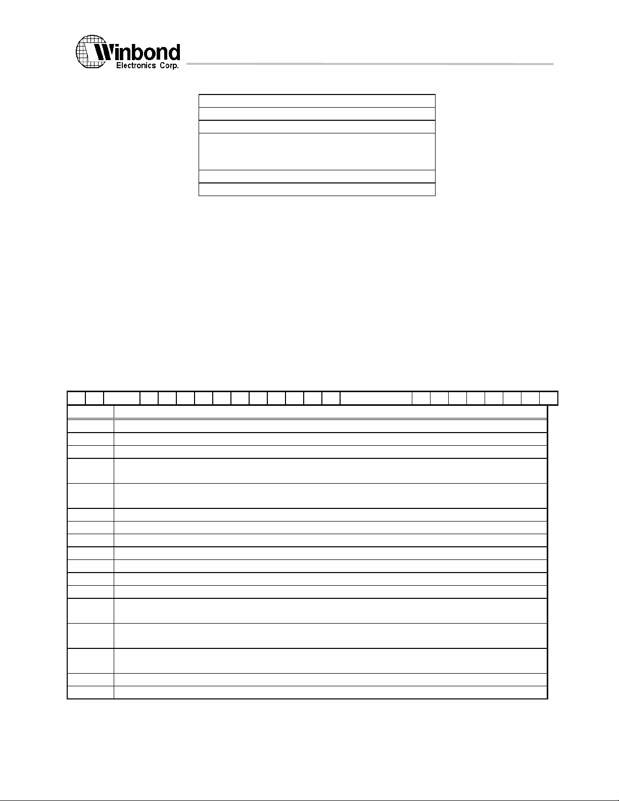
The processor state of W90K is encoded in a 32-bit register called the Processor Status Word (PSW). The
format of PSW is shown in figure 5.2. The old value of the PSW is saved in the Interrupt Processor Status Word (IPSW)
when interruption occurs. The PSW is set to the contents of the IPSW by the RFIR (RETURN FROM INTERRUPTION
and RESTORE) instruction.
1 1 1 1 1 1 1 2 2 2 2 2 2 2 3 3
0 1 2 ... 4 5 6 7 8 9 0 1 2 3 4 5 6 ... 3 4 5 6 7 8 9 0 1
Y Z rv E S T H L N X B C V M C/B rv G F R Q P D I
Field Description
13 Version 1.4, 10/8/97
The above information is the exclusive intellectual property of Winbond Electronics Corp. and shall not be disclosed, distributed or reproduced without permission from Winbond.
Page 14
W90210F
R
Recovery counter enable. When 1, recovery counter traps occur if bit 0 of the recovery counter is a 1. This
bit also enables decrementing of the recovery counter.
Q
Interrupt state collection enable. When 1, interruption state is collected.
P
Non-existent register bit.
D
Non-existent register bit.
I
External interruption, power failure interrupt, and low-priority machine check interruption unmask. When 1,
these interruptions are unmasked and can cause an interruption.
Figure 5.2 Processor Status Word
031CR 0
Recovery Counter
CR 1
reserved
CR 7
reserved
CR 8
Nonexistent registers
CR 9
Nonexistent registers
CR 10
reserved
SCR (8 bits)
CCR (8 bits)
CR 11
nonexistent
SAR (5)
CR 12
Nonexistent registers
CR 13
Nonexistent registers
CR 14
Interruption Vector Address
reserved
CR 15
External Interrupt Enable Masks
CR 16
Interval Timer
CR 17
Nonexistent registers
CR 18
Interruption Instruction Address Offset Queue
CR 19
Interruption Instruction Register
CR 20
Nonexistent registers
CR 21
Interruption Offset Register
CR 22
Interruption Processor Status Word
CR 23
External Interrupt Request Register
CR 24
Temporary Registers
CR 31
Temporary Registers
5.2.4 Control registers
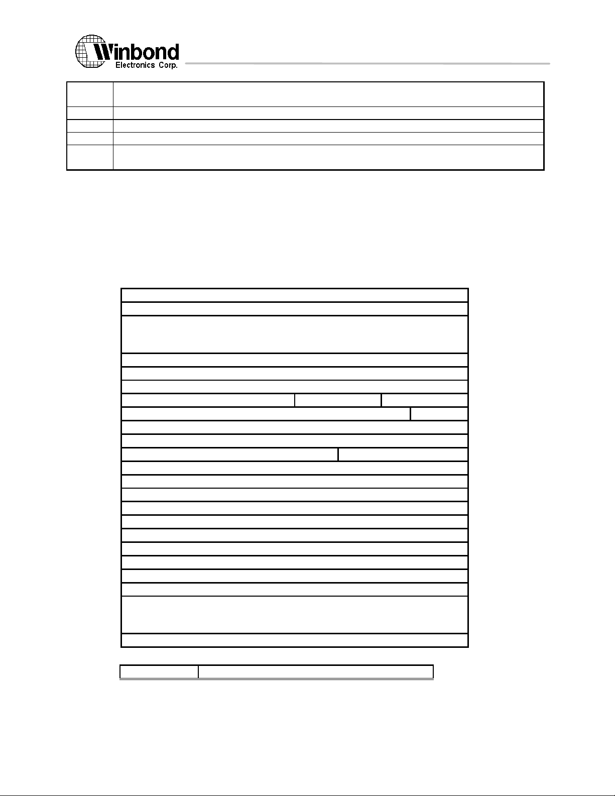
There are twenty-five control registers in W90210F, numbered CR0, and CR8 through CR31, which contain
system state information. Figure 5.3 shows the control registers. The access of CR 11, 16, 26, and 27 are described in
the following table (table 5.4). Those control registers not listed in table 5.4 are only accessible by code executing at the
most privileged level. Control registers 1 through 7 are reserved registers. The unused bits of the Coprocessor
Configuration Register are reserved bits. The unused bits of the Shift Amount Register are nonexistent bits. In Level
systems, CRs 8, 9, 12, 13, 17, and 20 are nonexistent registers.
•
•
•
•
•
•
Figure 5.3 Control registers
Privilege level for the access
14 Version 1.4, 10/8/97
The above information is the exclusive intellectual property of Winbond Electronics Corp. and shall not be disclosed, distributed or reproduced without permission from Winbond.
Page 15

W90210F
CR 11
read/write at any privilege level
CR 16
PSW 'S'=0: read/write by any privilege level
PSW 'S'=1: read/write by privileged software
CR 26, 27
readable at any privilege level
writable at the most privileged level
Others
Accessible only at most privileged level
Table 5.4 Access of control registers
AIR[0]
Internal configuration register
AIR[1]
PSW register
AIR[2]
TMR register
AIR[3]
Memory configuration register 1
AIR[4]
Memory configuration register 2
AIR[5]
Memory configuration register 3
AIR[6]
Memory configuration register 4
AIR[7]
PCO register (program counter)
5.2.5 W90210F External Interrupt Request register (EIRR; CR23)
Bit
Number
EI[0:4] External
Interrupt
Description
0 00000 Timer_Int Interval Timer (CR16) interrupt request
1 10000 2 01000 3 11000 Serial Serial port interrupt request from COM2
4 00100 INTA PCI bus INTA# interrupt request
5 10100 INTB PCI bus INTB# interrupt request
6 01100 INTC PCI bus INTC# interrupt request
7 11100 INTD PCI bus INTD# interrupt request
8 00010 Parallel_Int Parallel port interrupt request
9 10010 Serial_Int Serial port interrupt request from COM1
10 01010 DMA_Int DMA interrupt request
11 11010 TC_Int Timer/Counter interrupt request
12 - 31 - - Reserved
Table 5.5 External Interrupt Request Register
5.2.6 AIRs (Architecture Invisible Registers)
There are eight AIRs in the W90210F. AIR[0] controls the internal cache configuration, burst mode, and default
endian. AIR[0] is documented in this data sheet. AIR[1] and AIR[2] are reserved for chip testing by Winbond, and their
functions will not be disclosed to users. Attempting to access these two registers may cause programs to be executed
with unpredictable results. Memory configuration registers are used for programming the configuration of W90210F
memory space. AIR[7] is the PCO register, this AIR can only be accessed through the JTAG ICE interface.
Important: Enabling or disabling the internal I-cache with MTAIR[0] will invalidate all I-cache entries automatically.
Enabling the internal D-cache with MTAIR[0] will invalidate all cache entries without dirty data entries being written back.
Disabling the D-cache, however, will not invalidate cache entries.
Disabling the internal D-cache with MTAIR[0] will cause dirty data to be left in the D-Cache and not
automatically written into memory. When a program references the dirty data location, stale data in memory will be
returned. To prevent this, a cache invalidation routine should be performed before the internal D-cache is disabled. The
invalidation routine must flush all cache entries one by one. This will invalidate the cache and also write back any dirty
data.
AIR[1] and AIR[2] are reserved registers and should never be written to or read from them. Accessing these
registers will cause unpredictable result.
5.3 Implementation of the PA-RISC instructions
The above information is the exclusive intellectual property of Winbond Electronics Corp. and shall not be disclosed, distributed or reproduced without permission from Winbond.
Table 5.6 W90210F CPU core AIRs
15 Version 1.4, 10/8/97
Page 16
W90210F
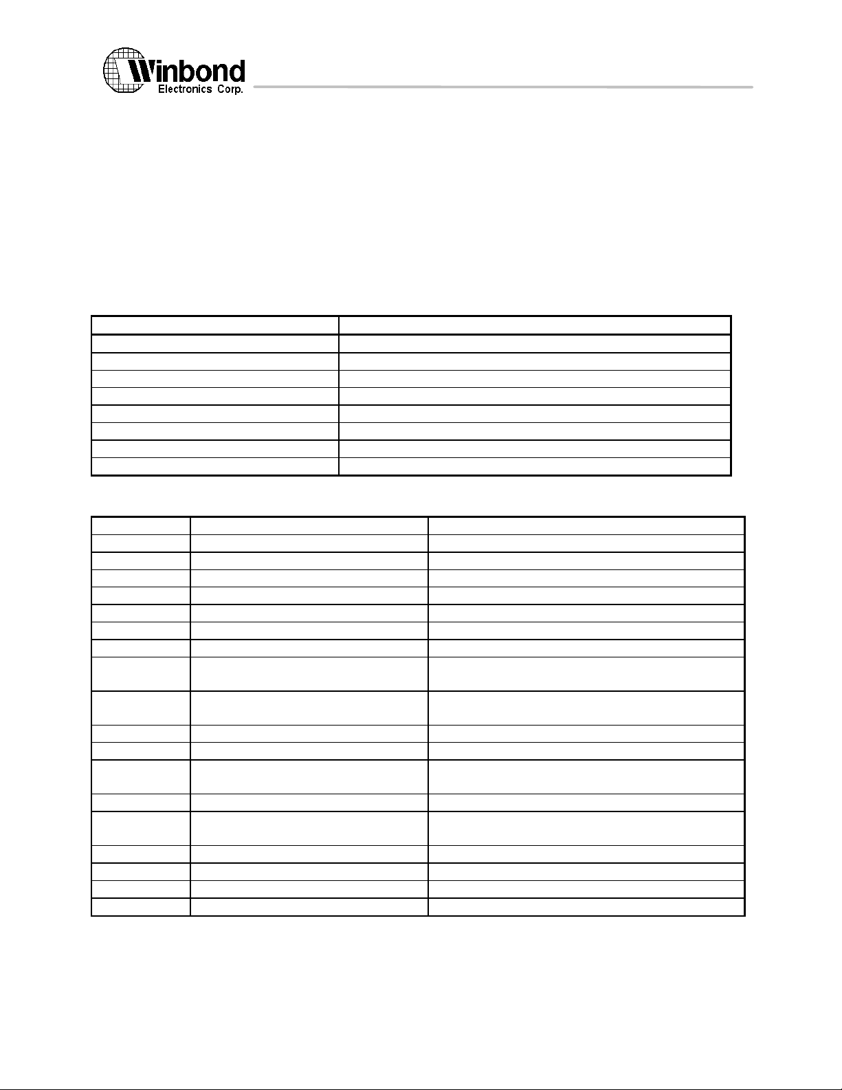
The W90210F CPU core implements all the instructions specified in the PA-RISC Rev. 1.1 third edition.
PDTLB
Purge data TLB
PITLB
Purge instruction TLB
PDTLBE
Purge data TLB entry
PITLBE
Purge instruction TLB entry
IDTLBA
Insert data TLB address
IITLBA
Insert instruction TLB address
IDTLBP
Insert data TLB protection
IITLBP
Insert instruction TLB protection
LPA
Load physical address
Undefined instruction
LCI
Load coherence index
Undefined instruction
LDWAX
Load word absolute index
Same as LDWX if priv=0
LDWAS
Load word absolute short
Same as LDWS if priv=0
STWAS
Store word absolute short
Same was STWS if priv=0
GATE
Gateway
Always promote priv to 0
BV
Branch vectored
Demote priv to any non zero value
BE
BLE
Branch external
Branch and link external
Demote priv to any non zero value, IASQ is nonexistent
RFI
RFIR
Return from interrupt
Return from interrupt and restore
IASQ is nonexistent
LDSID
Load space identifier
0 is written into specified GR
MTSP
Move to space register
Executed as null instruction
MTCTL
Move to control register
Executed as null instruction if target is 8,9,12,13,17 or
20
MFSP
Move from space register
is written into specified GR
MFCTL
Move from control register
0 is written into specified GR if source is 8,9,12,13,17 or
20
PROBER
Probe read access
Always set target GR to 1
PROBERI
Probe read access immediate
Always set target GR to 1
PROBEW
Probe write access
Always set target GR to 1
PROBEWI
Probe write access immediate
Always set target GR to 1
W90210F executes these instructions with results that comply to the PA-RISC architecture. MMU related instructions
are executed by W90210F as defined in the PA-RISC architecture for a Level 0 processor. PA-RISC multimedia
extension 1.0 instruction set is also supported by W90210F. To speed up multimedia operations in some applications,
three additional instructions are defined through the diagnostic instructions. In addition to that, debug SFU is provided to
enhance the debug capability. The chip also implements DIAG instructions defined by Winbond for chip testing,
diagnostics, and programming the internal AIR (architecture invisible register). These DIAG instructions comply with the
PA-RISC DIAG instructions.
5.3.1 Implementation of Level 0 instructions
In the Level 0 processor implementation, the S-fields of all instructions are ignored and have no effect on the
device functions. The following instructions for TLB handling are executed as null instructions, as specified in the
architecture reference manual:
Instruction Function
Table 5.7 Instructions executed as null instructions
Table 5.8 lists the differences in instruction execution results in a Level 0 processor.
Instruction Description Difference
5.3.2 Implementation of cache-related instructions
The above information is the exclusive intellectual property of Winbond Electronics Corp. and shall not be disclosed, distributed or reproduced without permission from Winbond.
Table 5.8 Summary of Level 0 instruction differences
16 Version 1.4, 10/8/97
Page 17
W90210F
It is assumed that in the W90210F application system all DMA transfers will be completed in order. The
SYNCDMA
Null
FDCE, FICE
See description above
FDC, FDCE, FIC, FICE, PDC
Affect internal cache only and are not broadcast to external bus.
HADD
Halfword parallel add
HSUB
Halfword parallel subtract
HAVE
Halfword parallel average
HSHRADD
Parallel halfword shift right and add
HSHLADD
Parallel halfword shift left and add
HALT
MTAIR
MFAIR
MTITAG
MFITAG
MTICAH
MFICAH
MTDTAG
MFDTAG
MTDCAH
MFDCAH
LDHU
HABSADD
instruction for DMA cache synchronization SYNCDMA will be executed as a null instruction. The W90210F CPU core
does not snoop the external bus to check the coherence of the cache. To ensure that the contents of the memory
remain consistent, devices outside the W90210F CPU can access only non-cacheable memory. FLUSH and purge
cache instructions will flush the internal cache only. The W90210F will not broadcast a flush or purge operation to the
secondary cache or other bus master (if any).
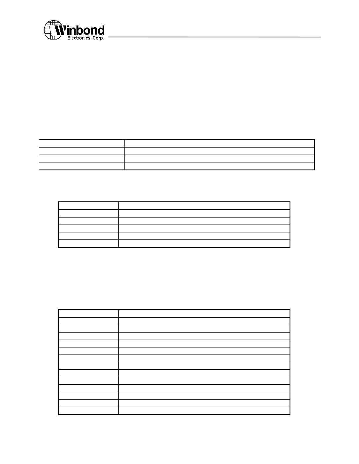
FICE and FDCE are implemented as described below.
• FICE will flush all instruction cache entries. All instruction entries become invalid after the execution of
FICE.
• FDCE is used to flush an individual cache entry. This instruction causes dirty data to be written back
to memory.
The data cache in the W90210F has 2 x 64 entries. To flush the entire data cache, a loop that execute a flush
to a single entry can be used to flush the entire data cache.
Instruction Execution result
Table 5.9 Cache-related instructions and execution results
5.3.3 PA-RISC multimedia extension instruction set
The PA-RISC Multimedia extensions consists of a set of instructions which speed up the execution of common
operations found in multimedia applications. Multimedia instructions perform multiple parallel operations in a single cycle.
Instruction Description
Table 5.10 PA-RISC multimedia instructions
5.3.4 DIAG instruction
DIAG instructions are a special instruction format defined by PA-RISC; the functions of these instructions
depend on the specific implementation. These instructions are used to program special control registers in the W90K
that are not visible in the PA-RISC architecture.
The DIAG instruction syntax is not supported by the assembler. A special macro file provided by Winbond must
be included in user programs. The macro converts DIAG assembly instructions into a format recognized by the
assembler. With the help of this file, users can employ the DIAG syntax described below for programming.
Instruction Description
Force W90210F CPU enter the HALT state
Copies value into a specified AIR from a general register
Copies value into a general register from AIR register
Copies value into a specified Instruction Tag from a general register
Copies value into a general register from a instruction tag
Copies value into a specified Instruction cache from a general register
Copies value into a general register from a instruction cache entry
Copies value into a specified data Tag from a general register
Copies value into a general register from a data tag
Copies value into a specified data cache from a general register
Copies value into a general register from a data cache entry
Load halfword and unpack
Halfword absolute and add
The above information is the exclusive intellectual property of Winbond Electronics Corp. and shall not be disclosed, distributed or reproduced without permission from Winbond.
17 Version 1.4, 10/8/97
Page 18

W90210F
Table 5.11 DIAG instructions
18 Version 1.4, 10/8/97
The above information is the exclusive intellectual property of Winbond Electronics Corp. and shall not be disclosed, distributed or reproduced without permission from Winbond.
Page 19
W90210F
5.4. Debug Special Function Unit
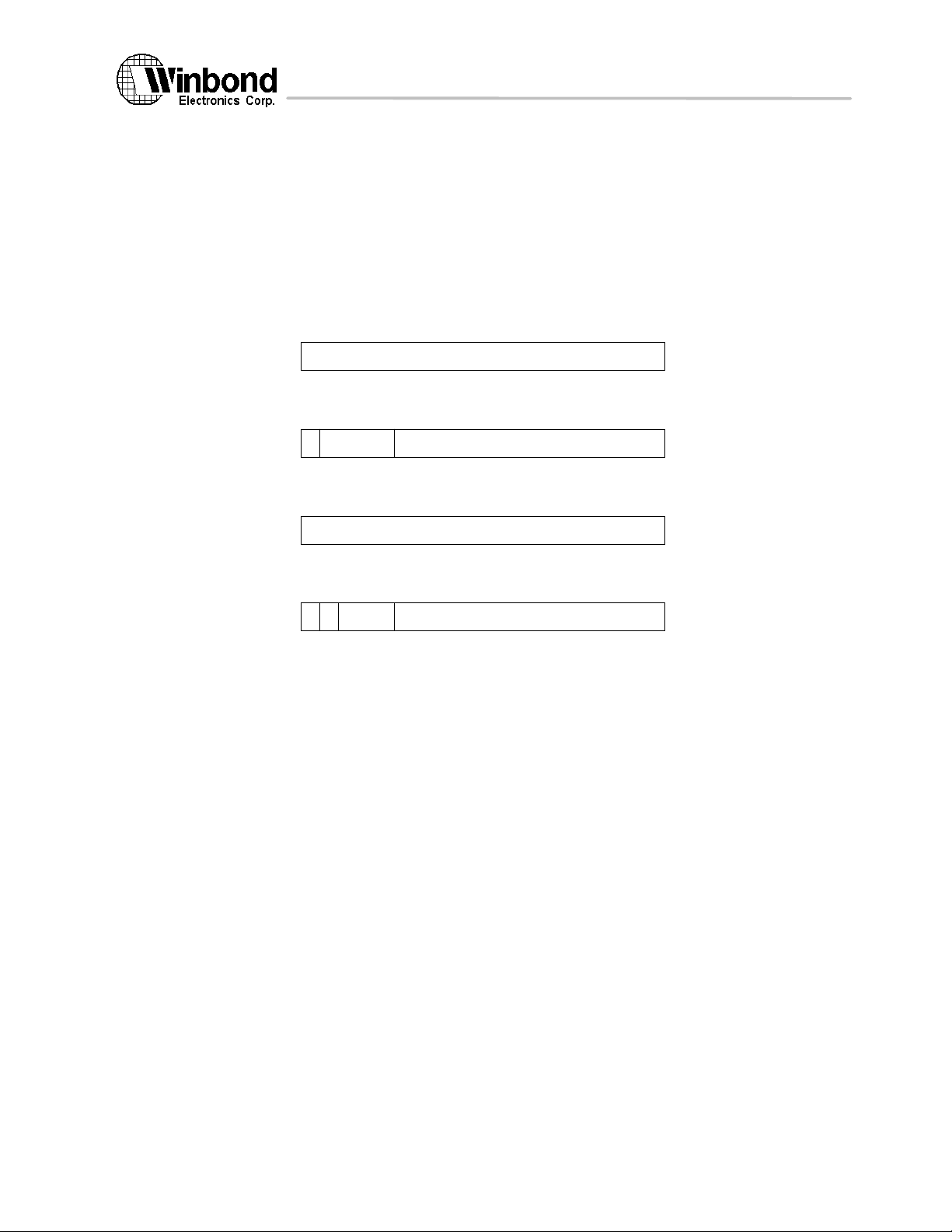
The debug special function unit is an optional, architected SFU which provides hardware assistance for
software debugging using breakpoints. The debug SFU is currently provided in the W90210F CPU core. The debug
SFU supports two sets of registers for both data breakpoints and instruction breakpoints.
For the instruction debug trap, the trapping address is stored in the interruption instruction address offset
queue (IIAOQ). For the data debug trap, the trapping address is stored in the interruption offset register (IOR).
The e bit in each IBAMR determines whether this instruction breakpoint is enabled. If the e bit is 1, any attempt
to execute an instruction (including nullified instructions) at an address matching the corresponding IBAOR will cause an
instruction debug trap. If the e bit is 0, that instruction breakpoint is disabled.
Instruction Breakpoint Address Offset Register (IBAOR0, IBAOR1):
0 31
address offset
IBAOR
Instruction Breakpoint Address Mask Register (IBAMR0, IBAMR1):
0 31
1 7 8
maskrve
IBAMR
Data Breakpoint Address Offset Register (DBAOR0, DBAOR1):
0 31
address offset
DBAOR
Data Breakpoint Address Mask Register (DBAMR0, DBAMR1):
0 31
1 2 7 8
r w rv
DBAMR
Figure 5.12 Debug SFU registers
mask
The r and w bits in each DBAMR determine the type of access this data breakpoint is enabled for. If the r bit is
1, any non-nullified load or semaphore instruction to an address matching the corresponding DBAOR will cause a data
debug trap. If the w bit is 1, any non-nullified store or semaphore instruction or cache purge operation to an address
matching the corresponding DBAOR will cause a data debug trap. If the r and w bits are both 0, the data breakpoint is
disabled.
For the control of the debug SFU, three bits are added to the PSW register.
Debug Trap Enable Bit (G): Bit 25 of the PSW is defined as the G-bit- the debug trap enable bit. When the G-bit is
1, the data debug trap and instruction debug trap are enabled; when 0, the traps are disabled. The G-bit is set to 0 on
interruptions.
Data Debug Trap disable Bit (Y): Bit 0 of the PSW is defined as the Y-bit. The Y-bit is set to 0 after the execution of
each instruction, except for RFI and RFIR instructions which may set it to 1. When 1, data debug traps are disabled.
Instruction Debug Trap disable Bit (Z): Bit 1 of the PSW is defined as the Z-bit. The Z-bit is set to 0 after the
execution of each instruction, except for RFI and RFIR instructions which may set it to 1. When 1, instruction debug
traps are disabled.
In addition, CCR bits 16- 23 are used as enable/disable bits for SFUs 0- 7. The debug SFU will use bit 17.
When bit 17 is enabled, the SFU #1 instructions will operate normally, but when disabled, all SFU #1 instructions will
take an assist emulation trap.
Two new exceptions are added to the architecture- one for instruction debugging and one for data debugging.
Instruction Debug Trap (30): Interruption #30 is now defined as the instruction debug trap. This trap belongs to
group 3.
Data Debug Trap (31): Interruption #31 is defined as the data debug trap. This trap belongs to group3.
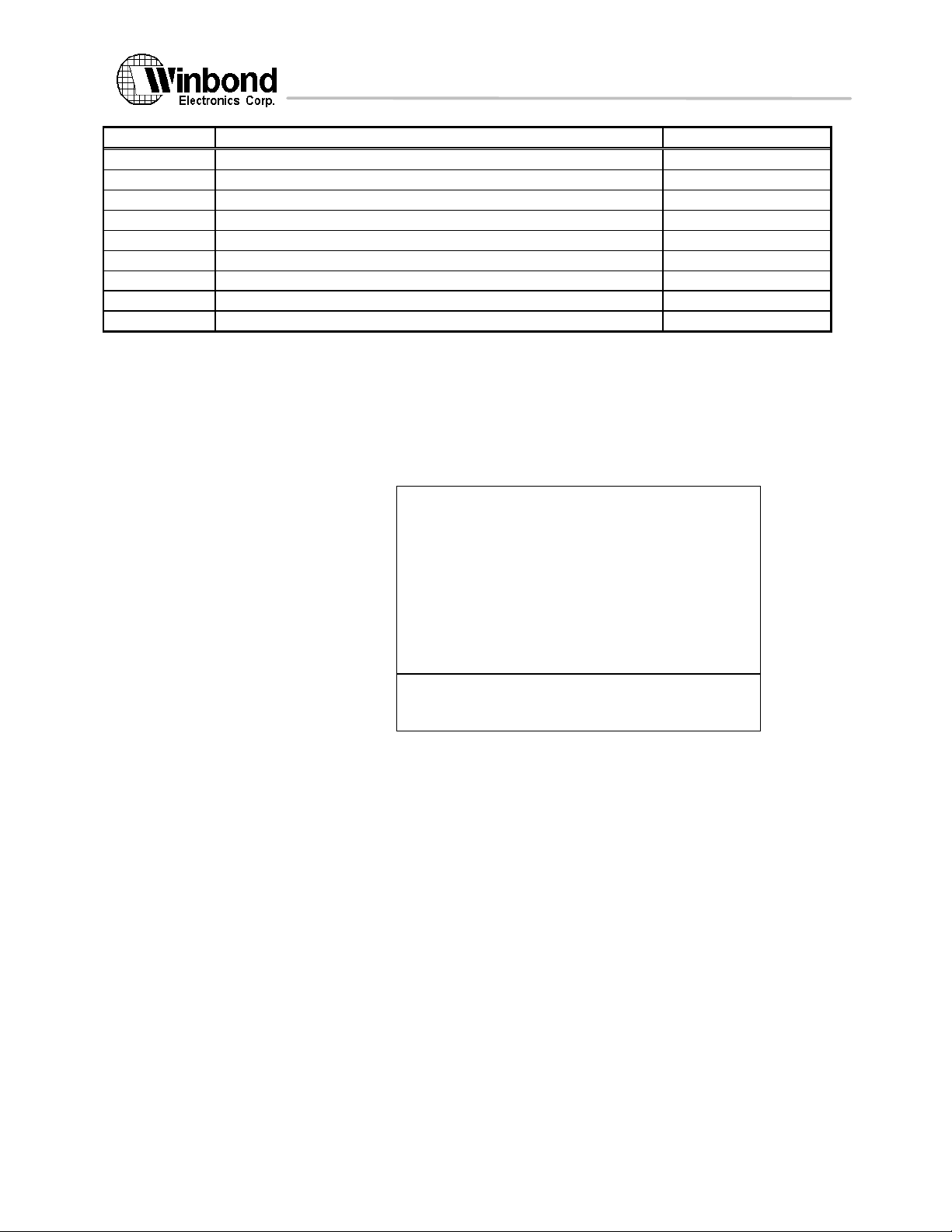
Following instructions are added for the debug SFU.
19 Version 1.4, 10/8/97
The above information is the exclusive intellectual property of Winbond Electronics Corp. and shall not be disclosed, distributed or reproduced without permission from Winbond.
Page 20
W90210F
Mnemonic
Description
Operation
MTDBAO
Move to data breakpoint address offset register
DBAOR[t]←GR[r]
MFDBAO
Move from data breakpoint address offset register
MTDBAM
Move to data breakpoint address mask register
MFDBAM
Move from data breakpoint address mask register
MTIBAO
Move to instruction breakpoint address offset register
MFIBAO
Move from instruction breakpoint address offset register
MTIBAM
Move to instruction breakpoint address mask register
MFIBAM
Move from instruction breakpoint address mask register
DEBUGID
Debug SFU identify
X'00000000
Memory Address Space
X'EFFFFFFF
X'F0000000
I/O Address Space
X'FFFFFFFF
GR[t]←DBAOR[r]
DBAMR[t]←GR[r]
GR[t]←DBAMR[r]
IBAOR[t]←GR[r]
GR[t]←IBAOR[r]
IBAMR[t]←GR[r]
GR[t]←IBAMR[r]
GR[t]←id number
Table 5.13 Debug SFU instructions
5.5 Addressing and access control
The W90210F implements real mode addressing. The total addressable space for the W90210F is 4 GB.
Objects in the memory and I/O system are addressed using 32-bit absolute addresses. An absolute pointer is a 32-bit
unsigned integer whose value is the address of the lowest addressed byte of the operand it designates. The address
mapping is same as that specified by the PA-RISC architecture.
5.5.1 Memory and I/O space
Figure 5.16 Memory and I/O addresses
Figure 5.16 shows the memory and I/O address space allocation.
Total memory address space available is (4 GB-256 MB). Total addressable I/O space is 256 MB.
Program address for I/O: Fxxxxxxx
W90210F CPU core output address: 0xxxxxxx
5.5.2 RESET addresses
The initial instruction address after a hardware reset is not defined in the PA-RISC architecture. Two reset
addresses are provided for W90210F CPU core. W90210F CPU core will sample the input pin "PA/486#" at the trailing
edge of RESET to determine the initial instruction address. When PA/486# pin is low, the initial address will be
000FFFF0; when PA/486# is high, it will be EFFFFFF0. This pointer ensures that the program starts execution from
ROM space when used in an X86-compatible board. W90210F CPU core has an internal pull down resistor that will set
W90210F CPU to generate X86-like initial address if the PA/486# is left unconnected.
For W90210F, the reset address is always EFFFFFF0.
5.5.3 Access control
Every instruction is fetched and executed at one of four privilege levels (numbered 0,1 2, 3) with 0 being the
most privileged. The privilege level is kept in the bits 30 and 31 of the current instruction's address. Base relative branch
instructions (BV, BE and BLE) will demote privilege level to any non zero value, if it changes it. GATEWAY instruction
promotes the privilege level to 0. Other branch instructions have word offset only and will not change privilege level.
20 Version 1.4, 10/8/97
The above information is the exclusive intellectual property of Winbond Electronics Corp. and shall not be disclosed, distributed or reproduced without permission from Winbond.
Page 21
W90210F
5.6 Interruptions
11High-priority machine check
2
Power failure interrupt
23Recovery counter trap
4
External interrupt
5
Low-priority machine check
30
Instruction debug trap
8
Illegal instruction trap
9
BREAK instruction trap
10
Privileged operation trap
311Privileged register trap
12
Overflow trap
13
Conditional trap
31
Data debug trap
22
Assist emulation trap
23
Higher-privilege transfer trap
424Lower-privilege transfer trap
25
Taken branch trap
Interruptions are anomalies that occur during instruction processing causing the flow control to be passed to an
interruption handling routine. The interruptions are categorized into four groups based on their priorities. Interruption
numbers in table 5.17 are the individual vector numbers that determine which interruption handler is invoked for each
interruption. The group numbers determine when the particular interruption will be processed during the course of
instruction execution. The order the interruptions are listed within each group determines the priority of simultaneous
interruptions(from highest to lowest).
Group interruption number Interruption
Table 5.17 Interruption number
Interruption handler routine begins execution at the address given by:
Interruption Vector Address + (32*interruption_number)
However, handler of HPMC will start at 'initial address + 4', where 'initial address is the first instruction address
issued by W90K after RESET. There are two initial address (determined by PA/486#) , X'000FFFF0 or X'EFFFFFF0.
HMPC handler will start from either X'000FFFF4 or X'EFFFFFF4. This arrangement is to ensure that HPMC handler will
start first at a ROM address that is more reliable than DRAM.
21 Version 1.4, 10/8/97
The above information is the exclusive intellectual property of Winbond Electronics Corp. and shall not be disclosed, distributed or reproduced without permission from Winbond.
Page 22
W90210F
6. Pipeline Architecture
The pipeline used in the W90210F CPU core is a typical five-stage pipeline. Most instructions are executed in
one single cycle except long instructions. Long instructions are FDC, FDCE, FIC, FICE, PDC, RFIR, and RFI. For
Branch instruction, one delay slot is needed.
The pipeline is shown below:
CLK CLK CLK CLK CLK CLK CLK
IA IF FR EX MM WB
IA IF FR EX MM WB
IA IF FR EX MM WB
IA: Instruction address calculation
IF: Instruction fetch
FR: Register fetch and decode
EX: Execution and data address calculation
MM: Memory reference for Load/Store instruction
WB: Write back to register file
Figure 6.1 W90K pipeline architecture
IA: The instruction address for the cycle is generated. The sources of the instruction address are n+1, branch
target, interrupt vector, IIAOQ, and reset pointer. The address is calculated and selected within half cycle.
IF: Instruction cache is fetched during this cycle. Instruction will be available before end of IF. IMISS (instruction
cache miss) will be available at the second half of IF.
FR: The instruction from IF stage is used to access the register file and decoded for execution. The bypass
control is also generated to select the correct bypass path. If the instruction is a cache miss, the pipeline will stall at this
stage.
EX: The instruction is executed in this stage. For branch instructions, a dedicated adder is used to calculate the
target address at the first half of EX (corresponding to the IA stage of the instruction after the delay slot). The condition
check is also performed in this stage for conditional branch instruction. Data address for memory reference instruction is
also calculated in this stage. For non-nullified MTCTL instruction, data will be written into CR at the end of the EX stage.
External traps (EI, HPMC, LPMC and PFW) will be sampled at the EX stage and piped to the WB stage for trap
handling.
MM: The data cache is referenced at this stage.
WB: The data from EX or MM stage will be written back to register file in the first half of the WB stage. The data
can be read out by the FR stage in the same cycle; otherwise one extra bypass will be needed. If the MM stage of this
instruction is a miss and a data dependence exists, the pipeline will stall at the WB stage; otherwise, the pipeline will
continue.
6.1 Branch prediction
Static branch prediction is used for conditional branch instructions in W90210F CPU core.
Forward branch: predict not taken
Backward branch:predict taken
22 Version 1.4, 10/8/97
The above information is the exclusive intellectual property of Winbond Electronics Corp. and shall not be disclosed, distributed or reproduced without permission from Winbond.
Page 23
W90210F
(1) Correct prediction
conditional branch
delay slot
predict address
conditional branch
delay slot
predict address (nullified)
correct address
Load r1
r1 used
CLK CLK CLK CLK CLK CLK CLK
IA IF FR EX MM WR
IA IF FR EX MM WR
IA IF FR EX MM WR
(2) Incorrect prediction
CLK CLK CLK CLK CLK CLK CLK CLK
IA IF FR EX MM WR
IA IF FR EX MM WR
IA IF FR EX MM WR
IA IF FR EX MM WR
Figure 6.2 Pipeline operation for branch prediction.
6.2 Load use interlock
Load use interlock: A one-cycle interlock will be forced by hardware when load use dependence occurs.
CLK CLK CLK CLK CLK CLK CLK CLK
IA IF FR EX MM WR
IA IF FR EX EX MM WR
IA IF FR FR EX MM WR
IA IF IA IF FR EX MM WR
Figure 6.3 Load-use interlock pipeline operation
23 Version 1.4, 10/8/97
The above information is the exclusive intellectual property of Winbond Electronics Corp. and shall not be disclosed, distributed or reproduced without permission from Winbond.
Page 24

W90210F
7. On-Chip Cache Memories
The W90210F contains a 4-Kbyte instruction cache and a 2-Kbyte data cache. Cache memories hold
instructions and data that are repetitively accessed by the CPU and thus reduce the number of references that must be
made to the slower main memory. The internal cache uses a Harvard architecture, so the bandwidth between the cache
and processor is 2 words/cycle. Separate address and data bus are provided for I-cache and D-cache (Harvard
architecture).
After reset, both internal caches are disabled and all memory accesses are forwarded to the external bus.
AIR[0] is used to enable and disable the internal caches. A DIAG instruction (MTAIR) is the only instruction that can
access AIR[0].
The instruction cache is a direct mapped cache and the data cache is a 2-way set associative cache. Common
features for both caches are:
•4 words per entry
•One valid bit per entry
•Wrap-around fill
The line size is four words with a single valid bit for all four words. The line size is the same as that of an i486
processor, since the W90210F CPU core is designed to use an 486-type bus. Four words per entry is an optimal value,
considering the relatively small internal cache and the external bus bandwidth available.
The cache controller will request the BIU (Bus Interface Unit) for missed addresses. A whole line will be filled
after a cache miss, since only one valid bit is available. The BIU will first return the word needed (not necessarily the first
word in the entry) for program execution, and the processor will continue once the first word is returned. The remaining
three words will be filled into the cache while the program is executed; this is the so-called wrap-around refill scheme.
Important: Attempting to enable an internal cache after it has been enabled and then disabled will lead to
unpredictable results, because the internal cache may contain stale data. Hence a cache invalidation routine that flushes
all cache entries one by one must be performed before an internal cache is disabled. This will invalidate the cache and
cause any dirty data to be written back to memory.
7.1 Instruction cache
Instruction cache is a 4-Kbyte direct mapped cache. The instruction cache is divided into four 1-Kbyte caches,
and each 1-Kbyte cache can be freezed individually by setting the corresponding cache freeze bit in the AIR[0].
The cache freeze function must be implemented by the pre-load method. User must fill the instruction cache
with the desired routines by MTITAG and MTICAH diagnostic instructions and then set the corresponding freeze bit to
freeze the particular routine in the instruction cache.
7.2 Data cache
The integrated Data cache has several features that are not shared by the I-cache. The features listed below
have been added to enhance the efficiency of the D-cache:
• Write-back cache with write-through option
• Hit under miss
• Separate byte write enable
The integrated D-cache is a write-back cache by default. This minimizes the number of bus cycles needed
between the CPU and the slow main memory system. Data are written back to main memory only when an entry with
dirty data is to be replaced by a new address.
The address range for write-through cache option is programmable. User can program the write-through base
register and the write-through region size register (memory configuration registers) by MTAIR instruction.
The "hit under miss" scheme is used in the W90210F. A cache hit data reference is completed in one cycle.
When data miss occurs the W90210F will continue execution as long as the data are not needed. The BIU will perform
data access for the miss cycle in parallel with the program execution. While the BIU is accessing the missed data, the
internal D-cache can still be accessed by following load/store instructions. The W90K will stall only when missed data are
24 Version 1.4, 10/8/97
The above information is the exclusive intellectual property of Winbond Electronics Corp. and shall not be disclosed, distributed or reproduced without permission from Winbond.
Page 25

W90210F
needed for the program execution (i.e., a data dependency is encountered) or when a second miss cycle occurs before
the first miss cycle is serviced. The "hit under miss" scheme helps to minimize the D-cache miss penalty.
Separate byte write enables are provided for store instructions. This feature enables the W90210F to execute
store byte(s) instructions without read-modify-write operation.
7.2.1 Write-through Cache Support
Normally, the data cache is a write-back cache. Range for the write-through cache address space can be
defined in the AIR.
Write-through base register[0:15]: This register defines the base address of the write-through address range.
Write-through region size register: This register defines the size of the write-through address range:
000: disable
001: 64K
010: 128K (base address must be multiple of 128K)
011: 256K (base address must be multiple of 256K)
100: 512K (base address must be multiple of 512K)
101: 1M (base address must be multiple of 1M)
110: 2M (base address must be multiple of 2M)
111: 4M (base address must be multiple of 4M)
Important: User must flush the data cache before setting up these two registers.
7.3 Non-cacheable address space
User can define two non-cacheable regions with sizes ranging from 64K to 4M Byte. BIU can use these two
ranges to decide whether current bus cycle is cacheable or not.
Non-cacheable base address register: This register defines the base address of the non-cacheable address
range.
Non-cacheable region size register: This register defines the size of the non-cacheable address range:
000: disable
001: 64K
010: 128K (base address must be multiple of 128K)
011: 256K (base address must be multiple of 256K)
100: 512K (base address must be multiple of 512K)
101: 1M (base address must be multiple of 1M)
110: 2M (base address must be multiple of 2M)
111: 4M (base address must be multiple of 4M)
The memory address space above 1MB, 2MB, 4MB, 8MB, 16MB, 64MB, 128MB or 256MB can also be turned
into a third non-cacheable region. This is defined by the system non-cacheable region register: 0000: all
cacheable
0001: above 1MB
0010: above 2MB
0011: above 4MB
0100: above 8MB
0101: above 16MB
0110: above 32MB
0111: above 64MB
1000: above 128MB
1001: above 256MB
25 Version 1.4, 10/8/97
The above information is the exclusive intellectual property of Winbond Electronics Corp. and shall not be disclosed, distributed or reproduced without permission from Winbond.
Page 26
W90210F
8. Megacells Description
8.1 DRAM Controller & ROM Controller
8.1.1 DRAM controller
The DRAM controller supports four separate banks of dynamic memory. Either X9 or X36 SIMMs are
supported. CAS#-before-RAS# refresh cycles are performed periodically, as determined by the refresh timer. The
DRAM controller must arbitrate between access requests and refresh requests. EDO fast page mode and parity check
are also supported.
CPU interface
Figure 8.1 DRAM controller block diagram
Bus
Interface
to
CPU core
Refresh Timer
DRAM Type Register
Bank Base Address
Registers
DRAM Configuration
Register
DRAM Timing
Register
RAS#[4]
CAS#[4]
MA[12]
MD[32]
WE#
For each bank of DRAM, there will be registers to specify the bank base address and the bank DRAM type:
Bank Base Address Register.
Bank Type Register.
DRAM Type Register is used to program the DRAM type of each bank.
DRAM Type
00 : 256K DRAM cell
01 : 1M DRAM cell
10 : 4M DRAM cell
11 : 16M DRAM cell
0 1 2 3 4 5 6 7
Bank
2
3
DRAM Type Register
Figure 8.2 DRAM Type register programming
0
1
Bank
Bank
Bank
DRAM Timing Register is used to program DRAM timing parameters:
2ah [6:7] Write cycle RAS# to CAS# delay.
[4:5] Read cycle RAS# to CAS# delay
[3] Write cycle CAS# pulse width.
[2] CAS# precharge time.
[0:1] RAS# precharge time.
2bh [6:7] Read cycle. CAS# pulse width.
[5] Refresh cycle. CAS# active to RAS# active delay.
[3:4] Refresh cycle. RAS# active to CAS# inactive delay.
[1:2] Refresh cycle. RAS# active pulse width.
[0] Parity check enable.
26 Version 1.4, 10/8/97
The above information is the exclusive intellectual property of Winbond Electronics Corp. and shall not be disclosed, distributed or reproduced without permission from Winbond.
Page 27
W90210F
DRAM configuration register is used to program the DRAM configuration:
Index
Bit No.
Description
00h
[0:7]
ROM bank 0 base address register[0:7]
01h
[0:7]
ROM bank 0 base address register[8:15]
02h
[0:7]
ROM bank 1 base address register[0:7]
[7] EDO fast page mode enable.
[6] Fast write mode enable
[5] Disable DRAM address range from A0000 to FFFFF
[4] Enable DRAM bank 0.
[3] Enable DRAM bank 1.
[2] Enable DRAM bank 2.
[1] Enable DRAM bank 3.
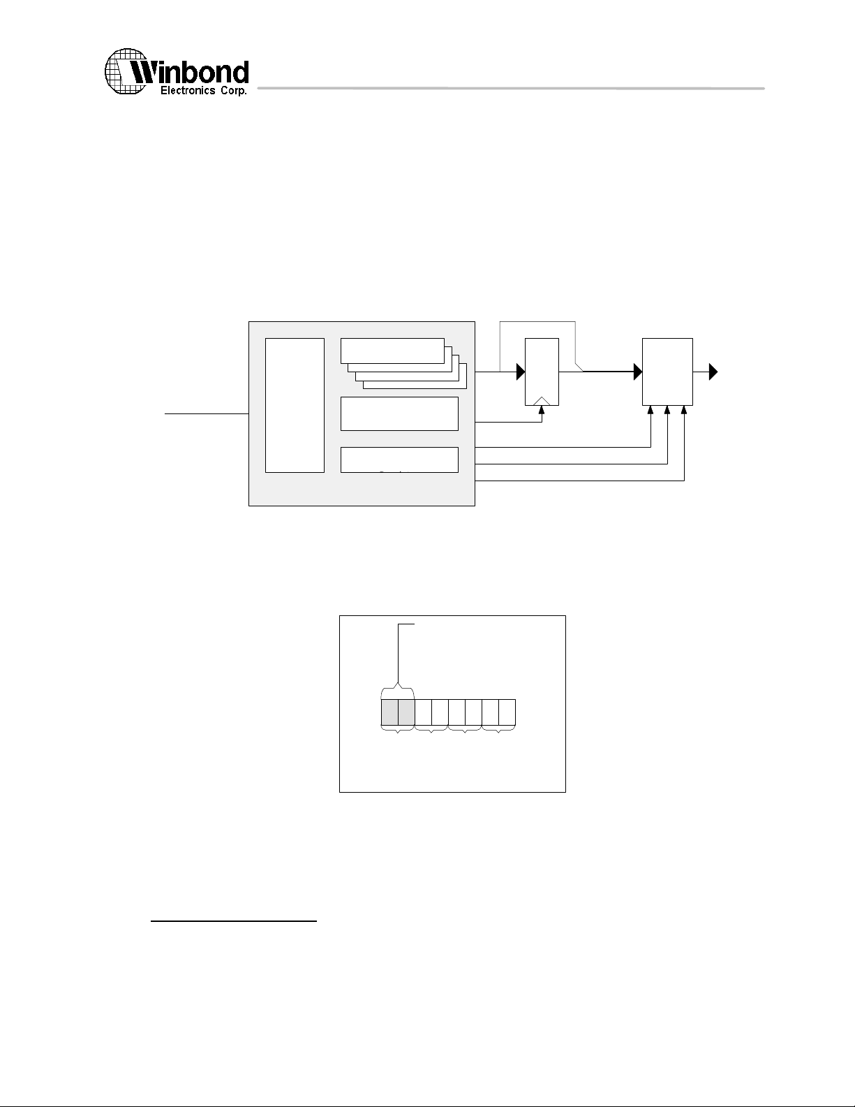
The refresh timer is a decrementing timers, which are clocked by a separated clock from the system clock.
When the refresh timer reaches zero, the refresh timer will generate a DRAM refresh request.
8.1.2 ROM controller
The ROM controller also supports upto four banks of ROM and the ROM can be 8-bit, 16-bit, or 32-bit.
Bank Base/Size
Registers
ROM AddressMA
CPU Interface
Bus
Interface
ROM and FLASH
Configure Register
ROM/FLASH Read
Wait State
Figure 8.3 ROM controller diagram
latch enable
cs#[4]
oe#
r/w#
For each bank of ROM, two registers are used to specify the bank address range:
ROM Bank Base Address Register.
ROM Bank Size Register.
ROM Configuration Register is used to program the ROM data bus size of each bank.
ROM Bus Size
00 : 8-bit ROM
01 : 16-bit ROM
10 : 32-bit ROM
11 : reserved
0 1 2 3 4 5 6 7
Bank
Bank
Bank
Bank
ROM Configuration Register
2
3
0
1
8-bit/
16-bit/
32-bit
ROM/
FLASH
Memory Data
ROM Wait State Register is used to program the number of wait states needed to access ROM.
8.1.3 Memory controller registers
In Memory Controller, two IO ports are used to access the entire register set: the index port is at address 22h
and the data port is at address 23h. To access a register, first write the index into the index port and then read or write
the data through the data port. The internal register for the memory controller is listed as follows:
ROM controller register :
The above information is the exclusive intellectual property of Winbond Electronics Corp. and shall not be disclosed, distributed or reproduced without permission from Winbond.
Figure 8.4 ROM configuration register programming
27 Version 1.4, 10/8/97
Page 28

W90210F
03h
[0:7]
ROM bank 1 base address register[8:15]
04h
[0:7]
ROM bank 2 base address register[0:7]
05h
[0:7]
ROM bank 2 base address register[8:15]
06h
[0:7]
ROM bank 3 base address register[0:7]
07h
[0:7]
ROM bank 3 base address register[8:15]
The register 0~7 has no default value.
08h
[0:7]
[0:3] ROM bank 0 size.
[4:7] ROM bank 1 size.
09h
[0:7]
[0:3] ROM bank 2 size.
[4:7] ROM bank 3 size.
0XXX → disable.
The default value is 0.
0ah
[0:7]
The default width of bank 0~3 is set by memory data bus bit 30 and 31.
0bh
[0:7]
[0:2] ROM access wait state.
The default wait state is 8.
[3] access ROM bank0 only. Default bank0 only.
[4] LA mode. Default LA mode.
Index Bit No. Description
20h [0:7] DRAM bank 0 base address register[0:7]
21h [0:7] DRAM bank 0 base address register[8:11]
22h [0:7] DRAM bank 1 base address register[0:7]
23h [0:7] DRAM bank 1 base address register[8:11]
24h [0:7] DRAM bank 2 base address register[0:7]
25h [0:7] DRAM bank 2 base address register[8:11]
26h [0:7] DRAM bank 3 base address register[0:7]
27h [0:7] DRAM bank 3 base address register[8:11]
The registers 20~27 has no default value.
Default 256K type.
29h [0:7] [0] Parity check enable. (default 0)
[1] Enable DRAM bank 3.(default 0)
[2] Enable DRAM bank 2.(default 0)
[3] Enable DRAM bank 1.(default 0)
[4] Enable DRAM bank 0.(default 0)
[5] Disable DRAM address range from A0000 to FFFFF.(default 0)
[6] Fast write mode enable.(default 0)
[7] EDO fast page mode enable.(default 0)
1000 → 64K, 1001 → 128K, 1010 → 256K, 1011→ 512K,
1100 → 1M, 1101 → 2M, 1110 → 4M, 1111 → 16M.
[0:1] bank 3 band width: 00→ 8_bit, 01→ 16_bit, 10→ 32_bit, 11→ reserved
[2:3] bank 2 band width: 00→ 8_bit, 01→ 16_bit, 10→ 32_bit, 11→ reserved
[4:5] bank 1 band width: 00→ 8_bit, 01→ 16_bit, 10→ 32_bit, 11→ reserved
[6:7] bank 0 band width: 00→ 8_bit, 01→ 16_bit, 10→ 32_bit, 11→ reserved
000 → wait 2 state. 001 → wait 3 state.
010 → wait 4 state. 011 → wait 5 state.
100 → wait 6 state. 101 → wait 7 state.
110 → wait 8 state. 111 → wait 9 state.
DRAM Controller Register
28h [0:7] [0:1] DRAM bank 3 type : 00 → 256K, 01 → 1M, 10 → 4M, 11 → 16M,
[2:3] DRAM bank 2 type : 00 → 256K, 01 → 1M, 10 → 4M, 11 → 16M,
[4:5] DRAM bank 1 type : 00 → 256K, 01 → 1M, 10 → 4M, 11 → 16M,
[6:7] DRAM bank 0 type : 00 → 256K, 01 → 1M, 10 → 4M, 11 → 16M,
28 Version 1.4, 10/8/97
The above information is the exclusive intellectual property of Winbond Electronics Corp. and shall not be disclosed, distributed or reproduced without permission from Winbond.
Page 29

W90210F
2ah [0:7] [0:1] RAS# precharge time.(default 0)
[2] CAS# precharge time.(default 0)
[3] Write cycle CAS# pulse width.(default 1)
[4:5] Read cycle RAS# to CAS# delay.(default 'b01)
[6:7] Write cycle RAS# to CAS# delay.(default 'b01)
2bh [0:7] [0:1] Refresh period.
00 : → 15us. (default).
[2] Refresh cycle. RAS# active pulse width after CAS# disactive.
[3:4] Refresh cycle. RAS# active to CAS# inactive delay.(default 'b01)
[5] Refresh cycle. CAS# active to RAS# active delay.(default 0)
[6:7] Read cycle CAS# pulse width.(default 'b01)
01 : → 30us.
10 : → 60us.
11 : → disable refresh (for test only).
The above information is the exclusive intellectual property of Winbond Electronics Corp. and shall not be disclosed, distributed or reproduced without permission from Winbond.
29 Version 1.4, 10/8/97
Page 30
W90210F
8.2 DMA Controller (DMAC)
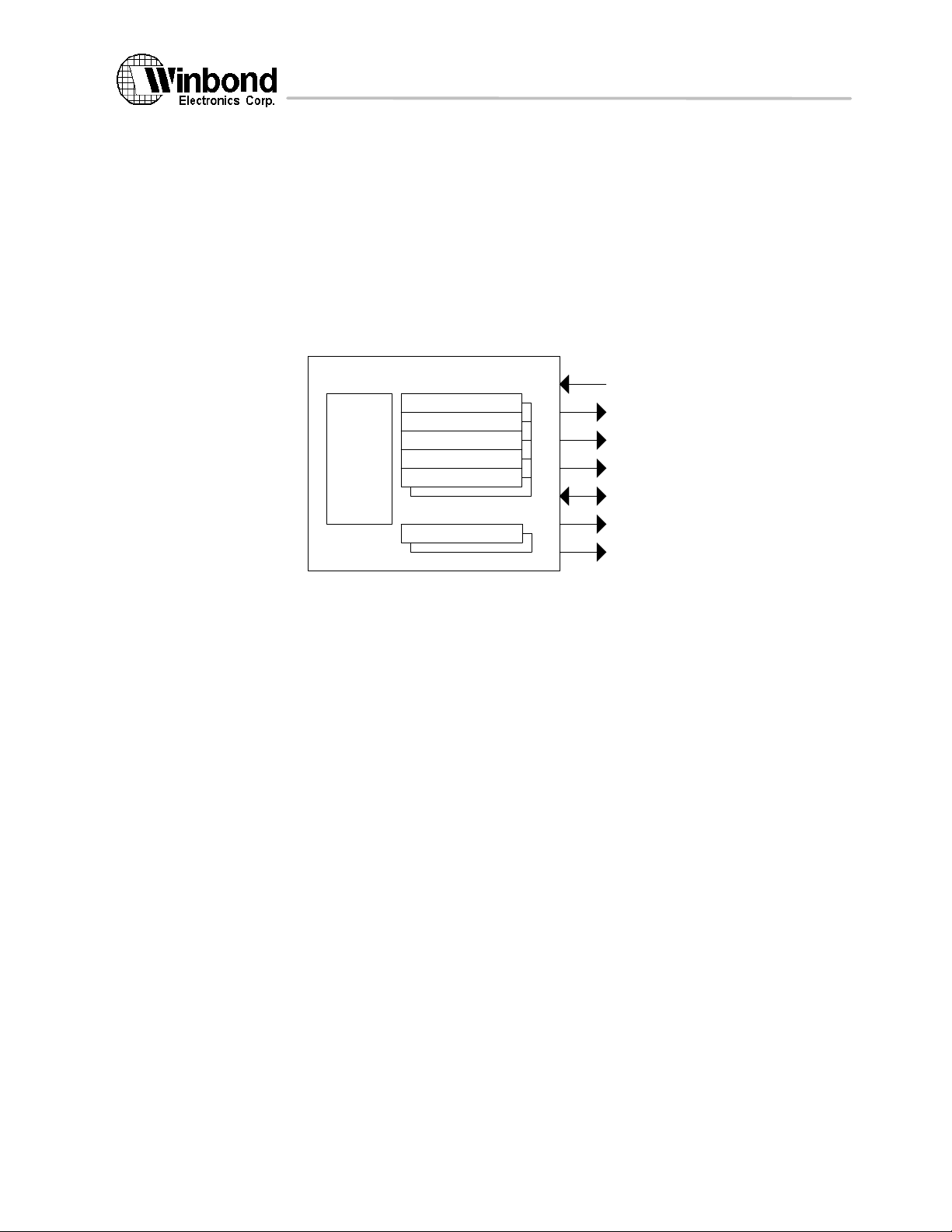
The DMAC megacell provides two DMA channels to support DMA transfers between 8-bit I/O devices and main
memory. The DMA mechanism will provide two different methods for performing DMA transfers: demand-mode
transfers and block-mode transfers. The DMAC hardware is responsible for synchronizing transfers with memory or
external devices.
When the DMAC is configured for demand mode, an external device requests a DMA transfer with a request
input (DREQ1:0#). The DMAC acknowledges the requesting device with an acknowledge signal (DACK1:0#) when
the requesting device is accessed.
In block mode, DMA transfers are not requested by an external device. The DMA operation is initiated by software
and continued until terminated or suspended. The DMA operation is started when the enable bit in the Configuration
Register is set.
DMAC megacell
Bus
Interface
SSAR
TSAR
LETH
MODE
TXCOUNT
DEV address
Figure 8.5 DMA controller
DREQ#[2]
DACK#[2]
IOR
IOW
IODATA[8]
DA[12]
CS[2]
In programming the megacell registers, the register address is defined by the BASE register plus the offset value.
8.2.1 Register Description:
Source Starting Address Register (SSAR0=080, SSAR1=084): SSAR is a read/write 32-bit register that contains
the starting address of the DMA transfer source.
Target Starting Address Register (TSAR0=081, TSAR1=085): TSAR is a read/write 32-bit register that contains the
starting address of the DMA transfer target.
Length/Count Register (LETH0=082, LETH1=086): LETH is a read/write 32-bit register that records the counts of
current DMA transfer.
30 Version 1.4, 10/8/97
The above information is the exclusive intellectual property of Winbond Electronics Corp. and shall not be disclosed, distributed or reproduced without permission from Winbond.
Page 31
W90210F
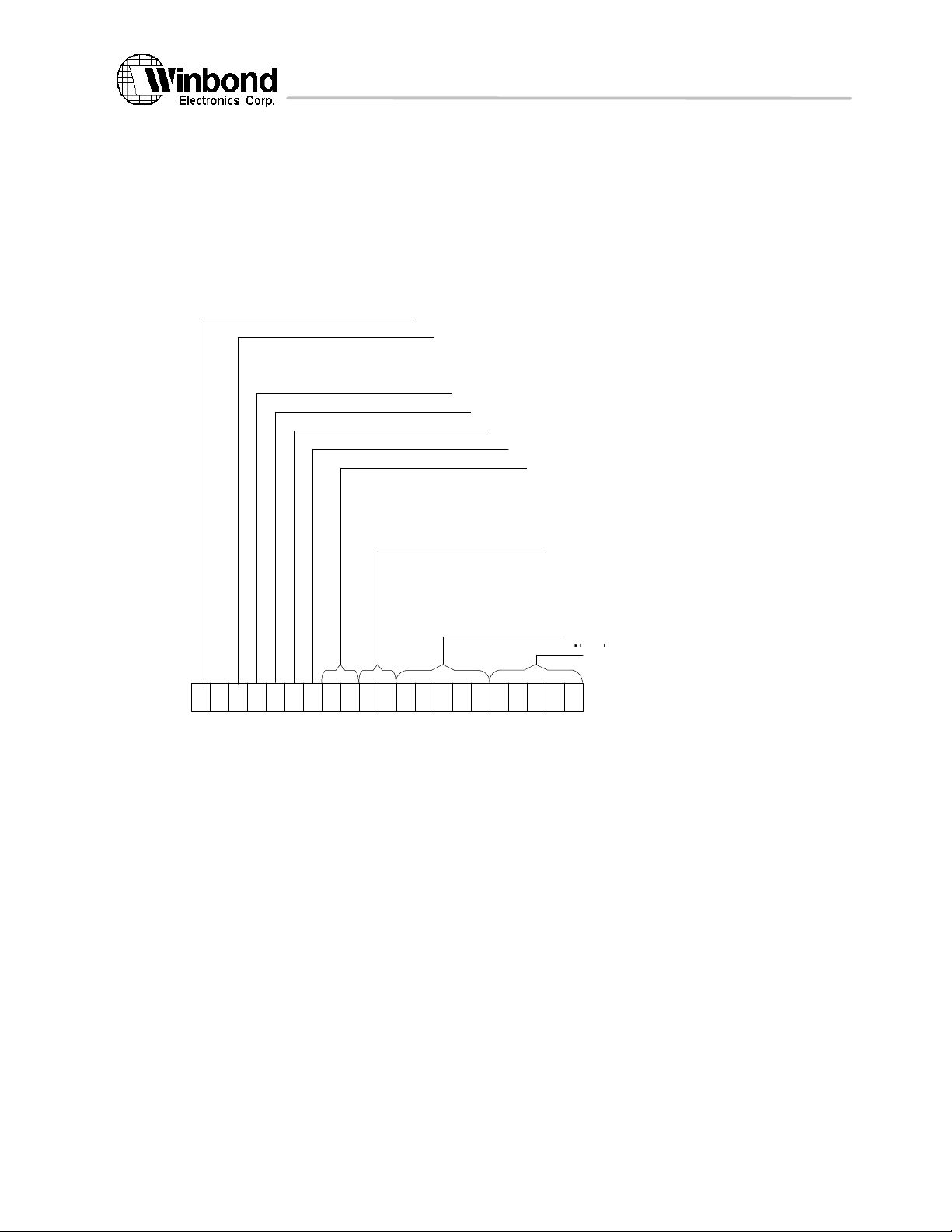
DMA Channel Mode Register (MODE0=20c, MODE1=21c): The MODE register specifies the operation mode of
each channel.
The Wait State Number specifies the number of wait state needed for the particular DMA channel.
The Recovery State Number specifies the number of wait state needed for the recovery of the DMA
channel.
The channel terminal count flags indicate that a DMA operation has stopped.
The DMA channel enable bits enable or suspend a DMA operation after a channel is set up. If a enable bit
for a channel is cleared when a channel is active, the DMA will be suspended after pending requests for the
channel are serviced. The DMA operation will resume normally when the bit is reset.
DMA Channel Enable Bit
Terminal Indicator
0: Polling
1: Interrupt
DMA is used by Parallel Port (ECP)
Terminal Count Flag
Transfer Start (only for memory-to-memory)
Transfer Type: Block (0) or Demand(1)
DMA I/O Type
00: 8-bit
01: 16-bit
10: 32-bit
11: reserved
DMA Transfer Type
00: memory to memory
01: memory to I/O
10: I/O to memory
11: reserved
Recovery State
Wait State
0 16 201511109876
1 2 3 4 5
MODE
Figure 8.6 Programming DMA controller MODE register
31 Version 1.4, 10/8/97
The above information is the exclusive intellectual property of Winbond Electronics Corp. and shall not be disclosed, distributed or reproduced without permission from Winbond.
Page 32
W90210F
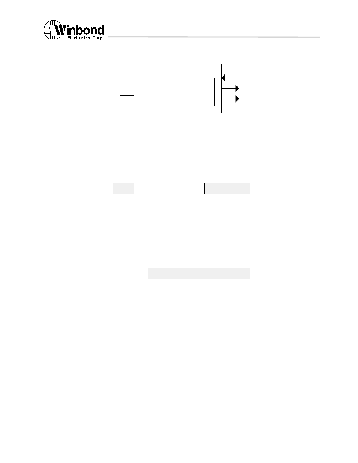
8.3 Timer / Counter
Timer/Counter megacell
TCR1
TICR1
TCR2
TICR2
0
31
TCR
24234
123
0
31
7
8
TICR
TCLK
Peripheral
Interface
Figure 8.7 Timer/Counter Megacell
Two 24-bit decrementing timers will be implemented. When the timer's interrupt enable bit is set to one and
the counter decrements to zero, the timer will assert the associated interrupt signal. The interrupt signal will assert one
of the 32 external interrupts defined by the EI bits in the control register. When a timer reaches zero, the timer
hardware reloads the counter with the value from the timer initial count register and continues decrementing.
Each timer is controlled and initialized by two registers: a timer control register and an timer initial count
register. These registers are all memory mapped I/O registers.
Timer Control register:
IECETI
Pre-Scalar (PS): A pre-scalar value can be used to divide the input clock.
Interrupt Enable bit (IE): When IE is set to one and the counter decrements to zero, the timer asserts its
interrupt signal to interrupt the CPU.
Counter Enable bit (CE): Setting the CE bit to one causes the timer to begin decrementing. Setting the
CE bit to zero stops the timer.
Timer Interrupt bit (TI): The timer sets this bit to one to indicate that it has decrement to zero. This bit
remain one until software sets it to zero.
reserved
pre-scalar
TINT1
TINT2
Timer Initial Count Register:
reserved
A 24-bit read/write register for the initial counter value.
The above information is the exclusive intellectual property of Winbond Electronics Corp. and shall not be disclosed, distributed or reproduced without permission from Winbond.
Timer Initial Count
32 Version 1.4, 10/8/97
Page 33
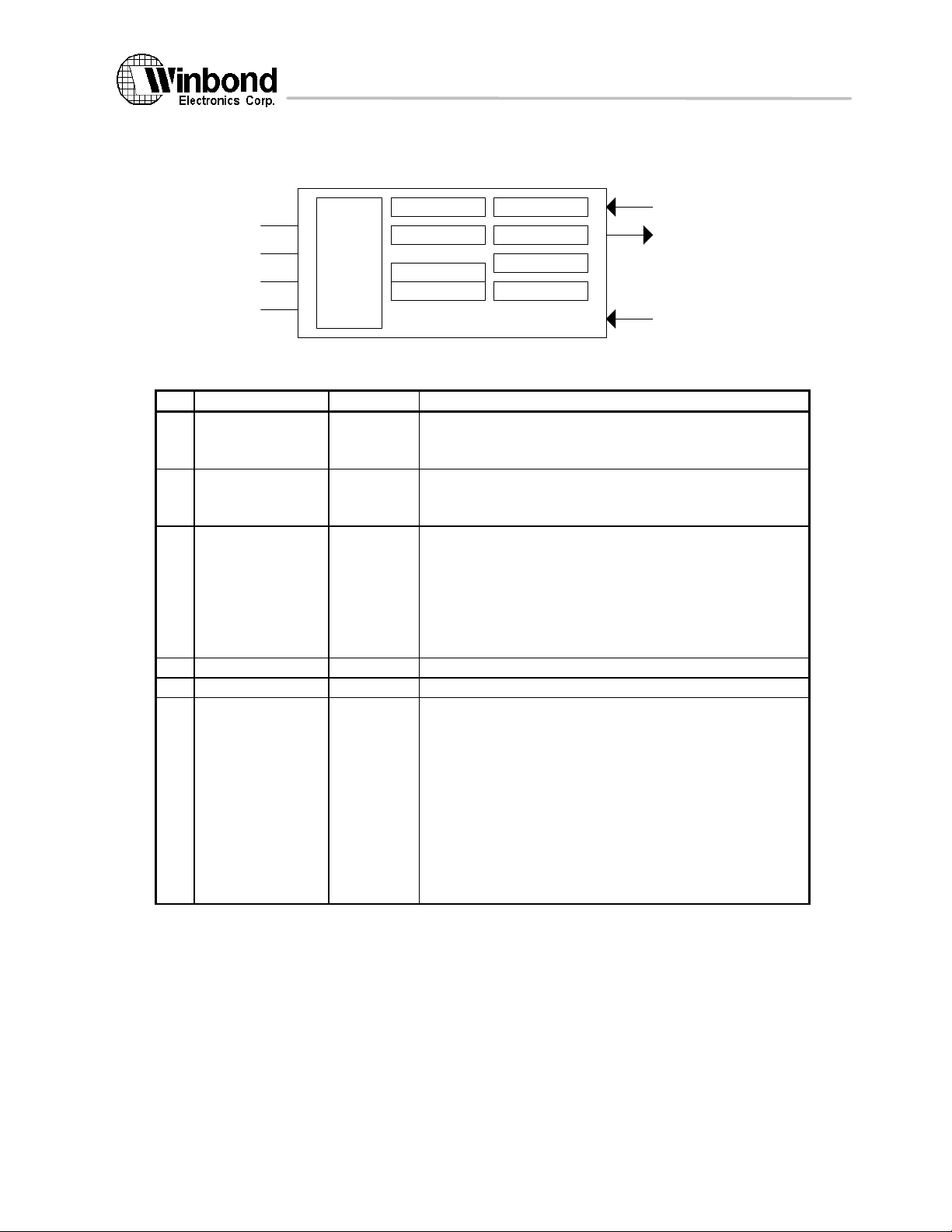
W90210F
8.4 Serial I/O
The serial I/O megacell implements a full-duplex, bi-directional UART with FIFO.
Input Shift Reg.
Output Shift
Control Logic
Timing generator
8.4.1 UART Register Definition
Peripheral
Interface
Input Buffer.
Output Buffer
Control Register
Status Register
Serial I/O megacell
Figure 8.8 Serial I/O with FIFO
Description
0 3F8, DLAB = 0 RBR[0:7] - Receiver Buffer Register.
- Read only.
- bit 7 is LSB.
0 3F8, DLAB = 0 THR[0:7] - Transmitter Holding Register.
- Write only.
- bit 7 is LSB.
1 3F9, DLAB = 0 IER[3:7] - Interrupt Enable Register.
* bit 7: Irpt_RDA enable (1/0- Enable/Disable).
* bit 6: Irpt_THRE enable (1/0- Enable/Disable).
* bit 5: Irpt_RLS enable (1/0- Enable/Disable).
* bit 4: Irpt_MOS enable (1/0- Enable/Disable).
- bit 3: Loop-back enable (1/0- Enable/Disable).
0 3F8, DLAB = 1 DLL[0:7] * Divisor Latch Register (LS).
1 3F9, DLAB = 1 DLM[0:7] * Divisor Latch Register (MS).
2 3FA IIR[0:7] - Interrupt Ident. Register.
- Read only.
SIN
SOUT
OSC
* bit 7: No Irpt pending (1/0- True/False).
* bit 6: Irpt ID bit (2).
* bit 5: Irpt ID bit (1).
* bit 4: Irpt ID bit (0).
- bit 3: DMA mode select (1/0- Mode 1/Mode 0).
- bit 2: RCVR trigger (LSB).
- bit 1: RCVR trigger (MSB).
- bit 0: FIFO mode enable (1/0- Enable/Disable).
33 Version 1.4, 10/8/97
The above information is the exclusive intellectual property of Winbond Electronics Corp. and shall not be disclosed, distributed or reproduced without permission from Winbond.
Page 34

W90210F
2 3FA FCR[0:7] - FIFO Control Register.
- Write only.
* bit 7: FIFO mode enable (1/0- Enable/Disable).
- bit 6: Reset RCVR FIFO. (self_clearing bit)
- bit 5: Reset XMIT FIFO. (self_clearing bit)
- bit 4: DMA mode select (1/0- Mode 1/Mode 0).
- bit 3: (Reserve).
- bit 2: (Reserve).
* bit 1: RCVR trigger (LSB).
* bit 0: RCVR trigger (MSB).
3 3FB LCR[0:7] - Line Control Register.
* bit 7: Word length select (LSB).
* bit 6: Word length select (MSB).
- bit 5: Number of stop bit.
- bit 4: Parity enable. (1/0- Enable/Disable)
- bit 3: Even parity select. (1/0- Even/Odd parity)
- bit 2: Stick parity enable. (1/0- Enable/Disable)
- bit 1: Set break.
- bit 0: Divisor Latch Access Bit (DLAB).
4 3FC TOR[0:7] - Time Out Register.
- bit 7 ~ 1: Time out bit-count.
- bit 0: Irpt_TOUT enable. (1/0- Enable/Disable)
5 3FD LSR[0:7] - Line Status Register.
- Read only.
- Write: Null operation.
- bit 7: Data Ready (DR).
- bit 6: Overrun Error (OE).
- bit 5: Parity Error (PE).
- bit 4: Framing Error (FE).
- bit 3: Break Interrupt (BI).
- bit 2: THR Empty (THRE).
- bit 1: Transmitter Empty (TEMT).
- bit 0: Error in RCVR FIFO (Err_RCVR).
6 3FE MOS[0:7]
7 3FF SCR[0:7] - Scratchpad Register.
- MODEM Status Register: non-exist
- Write: Null operation.
- Read: Get 8'b0
- Read/Write-able
Note: 1. Irpt_RDA: Received Data Available interrupt.
Irpt_THRE: Transmitter Holding Register Empty interrupt.
Irpt_RLS: Receiver Line Status Interrupt.
Irpt_MOS: MODEM Status Interrupt.
Irpt_TOUT: Receiver Time OUT Interrupt.
2. Baud rate = Frequency input / (16 * ({DLM, DLL} + 2))
34 Version 1.4, 10/8/97
The above information is the exclusive intellectual property of Winbond Electronics Corp. and shall not be disclosed, distributed or reproduced without permission from Winbond.
Page 35
W90210F
3. Interrupt Identification:
IIR[4] IIR[5] IIR[6] IIR[7]
- - - 1 - None
0 0 0 0 4th Irpt_MOS
0 0 1 0 3rd Irpt_THRE
0 1 0 0 2nd Irpt_RDA
1 1 0 0 2nd Irpt_TOUT
0 1 1 0 1st Irpt_RLS
* Irpt_RLS- caused by: Overrun Error or Parity Error or Framing Error or Break Interrupt.
- reset by: Reading LSR.
* Irpt_RDA- caused by: Received data >= RCVR trigger level.
- reset by: Reading RBR or RCVR FIFO drops below the trigger level.
* Irpt_TOUT- caused by: RCVR FIFO is non-empty and have not been accessed (Read/write) for the
time >= TOUR[1:7].
- reset by: Reading RBR.
* Irpt_THRE- caused by: THRE has been set.
- reset by: Reading IIR (if source of INTR is Irpt_THRE) or writing THR.
* Irpt_MOS- MODEM Status interrupt: Non-implemented.
4. RCVR Interrupt trigger level programing:
FCR[0] FCR[1]
0 0 1 bytes
0 1 4 bytes
1 0 8 bytes
1 1 14 bytes
Trigger level
Priority Irpt type
5. FCR[7] is always 1. Write FCR[7] to 0 has no effect.
6. Transmitter/Receiver Character length programing:
LCR[6] LCR[7]
0 0 5 bits
0 1 6 bits
1 0 7 bits
1 1 8 bits
The above information is the exclusive intellectual property of Winbond Electronics Corp. and shall not be disclosed, distributed or reproduced without permission from Winbond.
Character length
35 Version 1.4, 10/8/97
Page 36
W90210F
8.5 Parallel Port
The parallel port megacell implements the IEEE 1284 parallel port. The IEEE 1284 standard provides for high
speed bi-directional communication between the PC and an external peripheral.
The parallel port defines 5 modes of data transfer. Each mode provides a method of transfering data in either
the forward direction, reverse direction, or bi-directional data transfer. The defined modes are:
• Standard parallel port mode
• PS/2 parallel port mode
• Parallel port FIFO mode
• ECP parallel port mode
• Centronix Peripheral mode (Vendor specified mode)
Other modes defined in the IEEE 1284 standard like test mode and configuration mode are also supported.
8.5.1 ECP Register Description
1. Data Register (offset 378) R/W
0 7
This is the standard parallel port data register. Writing to this register in Standard mode shall drive data to the
parallel port data lines. In all other modes the drivers may be tri-stated by setting the direction bit in the dcr
register. Read to this register return the value on the data lines.
Standard mode:
write data_reg: cpu_data[0:7] → data_reg[0:7] → PAD_ED[0:7]
read data_reg: data_reg[0:7] → cpu_data
PS/2 mode, forward:
write data_reg: cpu_data → data_reg → PAD_ED
read data_reg: data_reg → cpu_data
PS/2 mode, reverse:
write data_reg: cpu_data → data_reg
read data_reg: PAD_ED → cpu_data
Centronix Peripheral mode:
read data_reg: PAD_ED → cpu_data
Other mode:
write data_reg: cpu_data[0:7] → data_reg[0:7]
read data_reg: undefined
2. DSR register (offset 379) Read only
This read-only register reflects the inputs on the parallel port interface.
Bit [0]- nBusy: inverted parallel port Busy signal
Bit [1]- nAck: parallel port nAck signal
Bit [2]- PError: parallel port PError signal
Bit [3]- Select: parallel port Select signal
Bit [4]- nFault: parallel port nFault signal
Bit [5:7]- reserved
3. DCR register (offset 37a) R/W
This register directly controls several output signals as well as enabling some functions. The drivers for nStrobe,
nAutoFd, nInit, and nSelectIn are open-collector in standard mode.
Bit [0:1]- reserved
Bit [2]- Direction
0 7
0 7
0: forward (default)
Drivers are enabled.
1: reserved
36 Version 1.4, 10/8/97
The above information is the exclusive intellectual property of Winbond Electronics Corp. and shall not be disclosed, distributed or reproduced without permission from Winbond.
Page 37

W90210F
In Standard mode or Parallel FIFO mode, this bit is forced to 0. The drivers are enabled, i.e. the
data pins of the parallel port are always outputs. Otherwise, this bit tri-states the data output
drivers, so that data will be read from the peripheral.
Bit [3]- ackIntEn
1: Enable an interrupt on the rising edge of nAck.
0: Disable the nAck interrupt (default)
Bit [4]- SelectIn; is inverted and then driven as parallel prot nSelectIn (default 1).
Bit [5]- nInit; is driven as parallel port nInit (default 1).
Bit [6]- autofd; is inverted and then driven as parallel port nAutoFd (default 0).
In centronic peripheral mode, when the nAck is active, the bit will be cleared by hardware.
Bit [7]- strobe; is inverted and then driven as parallel port nStrobe (default 0).
4. ECR register (offset 243) (R/W)
0 7
Bit[0:2]- mode (R/W)
000: Standard parallel port mode (default).
In this mode, FIFO is reset and common collector drivers are used on the control lines (nStrobe,
nAutoFd, nInit, and nSelectIn). Direction bit is cleared to "0".
001: PS/2 parallel port mode
The direction could be forward or reverse. In reverse direction, reading the data register returns the
value on the data lines not the value in the data register.
010: Parallel port FIFO mode
This is the same as Standard parallel port mode except that Pwords are written or DMAed to the
FIFO. FIFO data is automatically transmitted using the standard parallel port protocol. Note that
this mode is only useful when the direction bit is 0.
011: ECP parallel port mode
In the forward direction, Pwords is placed into the FIFO and transmitted automatically to the
peripheral using ECP protocol. In the reverse direction, bytes are moved from the ECP data port
and packed into Pwords in the FIFO. All drivers have active pull-ups.
100: Centronic peripheral mode
In this mode, the parallel port acts as a reverse port in centronics mode and the direction bit is
forced to 1. The nAutofd bit (DCR bit 6) is cleared, nAck is active until nAutofd bit (DCR bit 6) is
set to 1 by software. And the parallel port data will be latched in the data register.
101: Reserved
110: Test mode
In this mode, the FIFO may be read or written, but the data will not be transmitted on the parallel
port. Using this mode to test the depth of the FIFO, the write-threshold, and the read-threshold.
111: Configuration mode
In this mode, the CNFGA and CNFGB registers are accessible at addresses 244 and 246
Bit[3]- nErrIntrEn (R/W, Valid only in ECP mode)
1: Disable the interrupt generated on the asserting edge of nFault (default).
0: Enables an interrupt pulse on the high to low edge of nFault.
Note that an interrupt pulse will be generated if nFault is asserted and this bit is written from a "1" to a
"0". This prevents interrupts from being lost in the time between the read of the ecr and the wrtie of the
ecr.
Bit[4]- dmaEn (R/W)
1: Enables DMA, DMA starts when serviceIntr (bit 5) is 0.
0: Disables DMA unconditionally (default).
Bit[5]- serviceIntr (R/W)
1: Disables DMA and all of the service interrupts (default).
0: Enables one of the following 3 cases of interrupts. Once one of the 3 service interrupts has
occurred, serviceIntr bit shall be set to a "1" by the hardware. Writing this bit to a "1" will not cause
an interrupt.
case 1: dmaEn = 1
During DMA (this bit is set to a 1 when terminal count is reached)
case 2: dmaEn = 0, direction = 0
This bit shall be set to 1 whenever there are writeIntrThreshold or more Pwords free in the
FIFO.
case 3: dmaEn = 0, direction = 1
37 Version 1.4, 10/8/97
The above information is the exclusive intellectual property of Winbond Electronics Corp. and shall not be disclosed, distributed or reproduced without permission from Winbond.
Page 38
W90210F
This bit shall be set to 1 whenever there are readIntrThreshold or more valid Pwords to be read
from FIFO.
Bit[6]- Full (Read only)
1: direction = 0 The FIFO cannot accept another Pword.
1: direction = 1 The FIFO is completely full.
0: direction = 0 The FIFO has at least 1 free Pword
0: direction = 1 The FIFO has at least 1 free byte.
Bit[7]- empty (Read only)
1: direction = 0 The FIFO is completely empty
1: direction = 1 The FIFO contains less than 1 Pword of data
0: direction = 0 The FIFO contains at least 1 byte of data
0: direction = 0 The FIFO contains at least 1 Pword of data
5. CONFIGA register (offset 244) (R/W only in configuration mode)
0 7
Bit [0]- Indicates if interrupts are pulsed or level (Read only)
0: pulse
1: level
Bit [1:3 ]- Pword size (R/W)
001: Pword size = 1 byte
010: Pword size = 4 byte
000 and 011 ~ 111: reserved
Bit [4]- reserved
Bit [5]- nByteInTransceiver (Read only)
0: When transmiting (at host recovery), there is one byte in the transceiver waiting to be transmitted
that does not affect the FIFO full bit.
Bit [6:7]- Snapshot of the Pword
This field is not used for Pword size of 1 byte.
For host recovery situations these bits indicate what fraction of a Pword was not transmitted so that
software can re-transmit the unsent bytes. If the Pword size is 4 bytes the value of these two bits is a
snapshot of the last Pword being transmitted in mode 011 event 35 when the FIFO was reset (port
was transitioned from mode 011 to mode 000 or 001)
00- the Pword at the head of the FIFO contained a complete Pword
01- the Pword at the head of the FIFO contained only 1 valid bytes.
10- the Pword at the head of the FIFO containeed 2 valid bytes.
11- the Pword at the head of the FIFO contained 3 valid bytes.
6. Reverse address register (offset 245) (Read only)
0 7
Bit [0:1]- Reserved
Bit [2]- Tag_all
Bit [3:6]- Tag0, Tag1, Tag2, Tag3
Bit [7]- Tag
1: To indicate the unread bytes of the FIFO storing the reverse data/ command that has at least
one address bytes.
0: There is no address byte in the FIFO
to check if there is one byte of the following read Pword = 4 bytes is the reverse address. Tag0,
Tag1, Tag2 and Tag3 are individually for the byte0, byte1, byte2 and byte3 of the Pword
to check if the byte of the following read Pword (1 byte) is the reverse address.
38 Version 1.4, 10/8/97
The above information is the exclusive intellectual property of Winbond Electronics Corp. and shall not be disclosed, distributed or reproduced without permission from Winbond.
Page 39
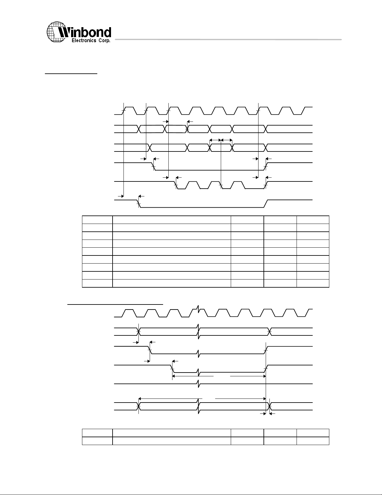
W90210F
9. Timing Diagram
PCLKRCS0# -
MA19 - MA
0
ROMRW
#
MD31 - MD0ROMOE
#
9.1 Memory controller
9.1.1 DRAM AC Timimg
MA11 - MA0
PCLK
t
av
tdst
dh
MD31 - MD0
t
rv1
RAS3# - RAS0#
CAS3# - CAS0#
t
wv
WE#
Symbol Parameter Min Max Unit
t
t
t
t
t
t
t
t
9.1.2 ROM AC Timimg
RAS# valid delay ref. to PCLK rising ns
RAS# valid delay ref. to PCLK rising ns
CAS# valid delay ref. to PCLK rising ns
RAS# valid delay ref. to PCLK rising ns
WE# valid delay ref. to PCLK rising ns
Memory data setup time ns
Memory data hold time ns
Memory address valid delay ns
9.1.2.1 Flash ROM Write Timimg
t
cv1
t
t
rv2
cv2
t
as
t
cs
t
wp
t
ds
t
dh
Symbol Parameter Min Max Unit
t
The above information is the exclusive intellectual property of Winbond Electronics Corp. and shall not be disclosed, distributed or reproduced without permission from Winbond.
Address setup time ns
39 Version 1.4, 10/8/97
Page 40
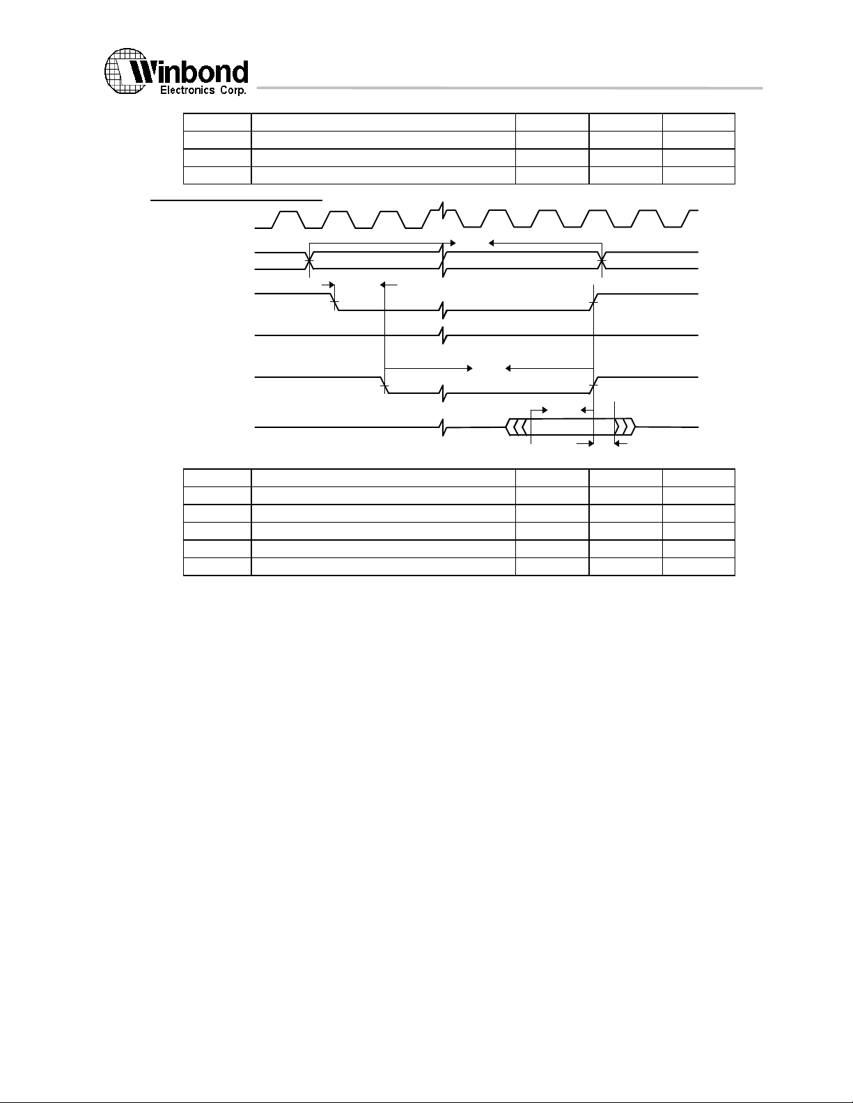
W90210F
t
PCLKRCS0# -
MA19 - MA
0
ROMRW
#
MD31 - MD0ROMOE
#
t
t
t
Chip select setup time ns
Data setup time ns
Data hold time ns
Flash ROM write pulse width 7 PCLK
9.1.2.2 ROM Read Timimg
Symbol Parameter Min Max Unit
t
t
t
t
t
Access time 3 PCLK
Chip select setup tome ns
Output enable pulse ns
Data setup tome ns
Data hold time ns
t
ac
t
cs
t
op
t
ds
t
dh
40 Version 1.4, 10/8/97
The above information is the exclusive intellectual property of Winbond Electronics Corp. and shall not be disclosed, distributed or reproduced without permission from Winbond.
Page 41
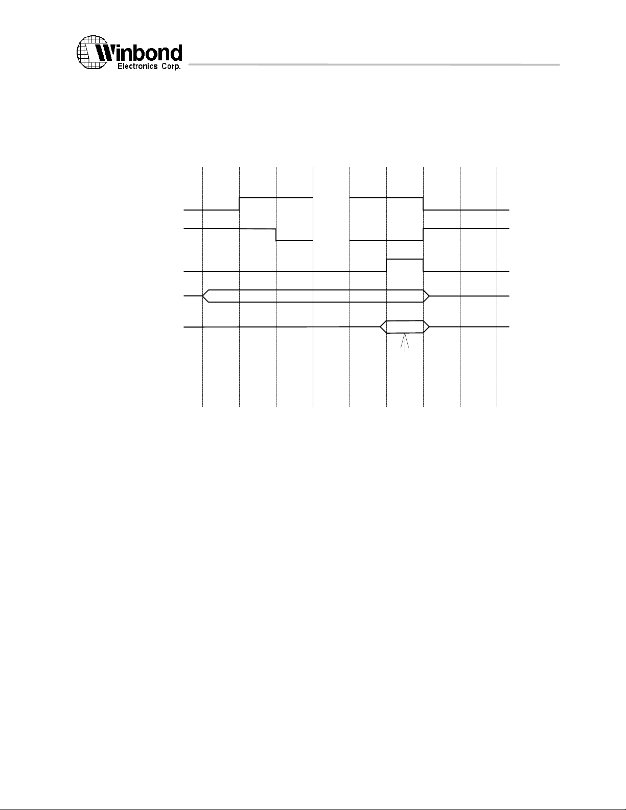
W90210F
9.2 DMA Controller
9.2.1 DMA device register read timing
DMA device register read timing
CS
IOR
DMARDY
DA<0:11>
DD<0:7>
~~
~~
~~
~~
Address
valid data
41 Version 1.4, 10/8/97
The above information is the exclusive intellectual property of Winbond Electronics Corp. and shall not be disclosed, distributed or reproduced without permission from Winbond.
Page 42
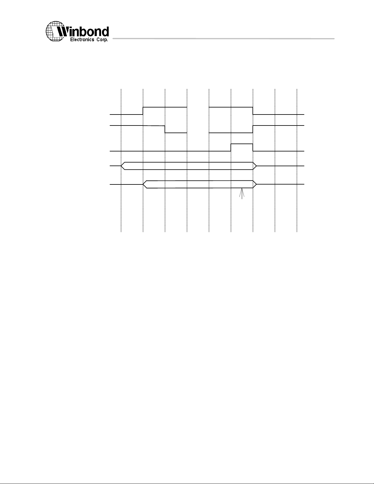
W90210F
9.2.2 DMA device register write timing
DMA device register write timing
CS
IOW
DMARDY
DA<0:11>
DD<0:7>
~~
~~
~~
~~
Address
valid data
42 Version 1.4, 10/8/97
The above information is the exclusive intellectual property of Winbond Electronics Corp. and shall not be disclosed, distributed or reproduced without permission from Winbond.
Page 43
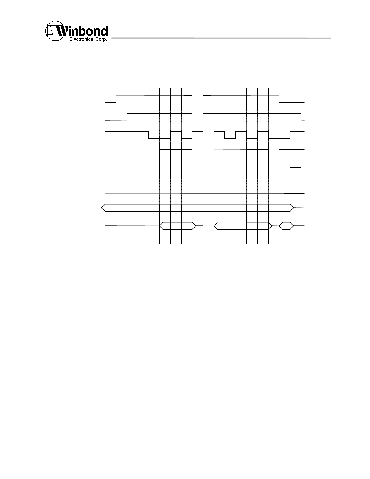
W90210F
9.2.3 DMA demand mode data read cycles
DMA cycle -- data read timing (demand mode)
~
DREQ
DACK
~
~
~
IOR
DMARDY
TC
CS
DA<0:11>
DD<0:7>
~
~
~
~
Do'nt care
~
~
43 Version 1.4, 10/8/97
The above information is the exclusive intellectual property of Winbond Electronics Corp. and shall not be disclosed, distributed or reproduced without permission from Winbond.
Page 44
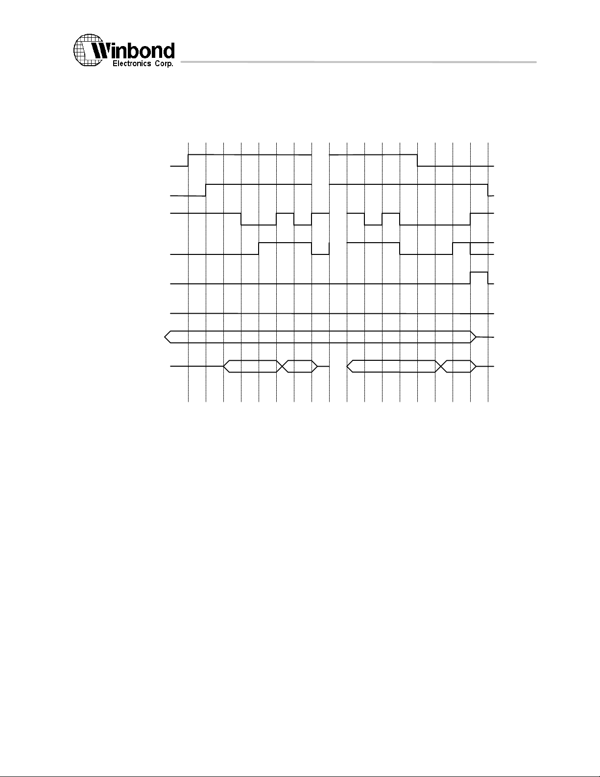
W90210F
9.2.4 DMA demand mode data write cycles
DMA cycle -- data write timing (demand mode)
~
DREQ
DACK
~
~
~
IOW
DMARDY
TC
CS
DA<0:11>
DD<0:7>
~
~
~
~
Do'nt care
~
~
44 Version 1.4, 10/8/97
The above information is the exclusive intellectual property of Winbond Electronics Corp. and shall not be disclosed, distributed or reproduced without permission from Winbond.
Page 45
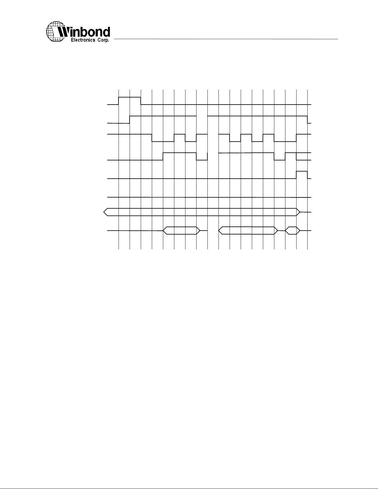
W90210F
9.2.5 DMA block mode data read cycles
DMA cycle -- data read timing (block mode)
DREQ
~
DACK
~
IOR
DMARDY
TC
CS
DA<0:11>
DD<0:7>
~
~
~
~
Do'nt care
~
~
45 Version 1.4, 10/8/97
The above information is the exclusive intellectual property of Winbond Electronics Corp. and shall not be disclosed, distributed or reproduced without permission from Winbond.
Page 46
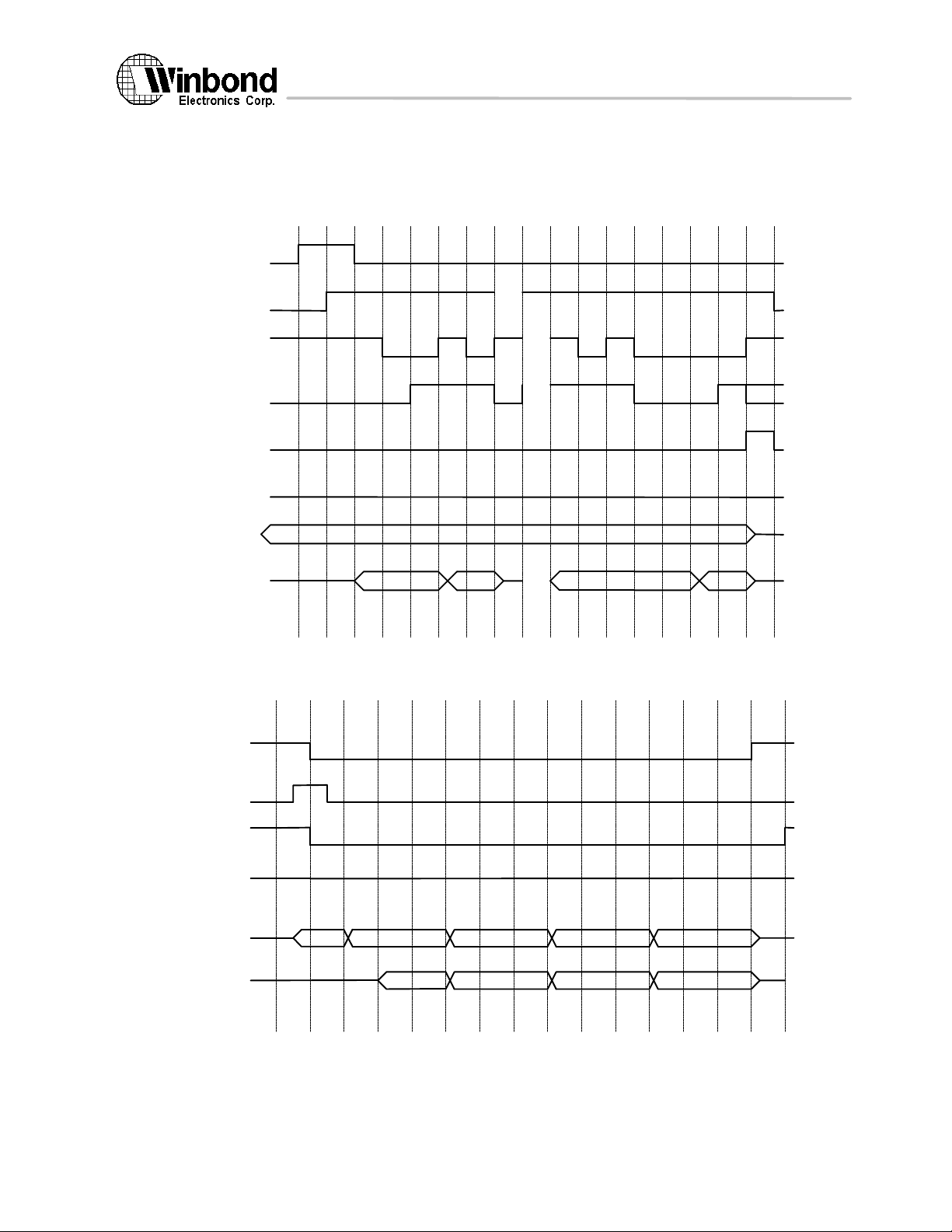
W90210F
9.2.6 DMA block mode data write cycles
DMA cycle -- data write timing (block mode)
DREQ
~
DACK
~
IOW
DMARDY
TC
CS
DA<0:11>
DD<0:7>
ROM/FLASH Read timing
RCS_
~
~
~
~
Do'nt care
~
~
MADDR<0:11>
ROMEN
ROM_OE_
ROM_RW_
MD<0:31>
or
MD<0:15>
or
MD<0:7>
46 Version 1.4, 10/8/97
The above information is the exclusive intellectual property of Winbond Electronics Corp. and shall not be disclosed, distributed or reproduced without permission from Winbond.
Page 47
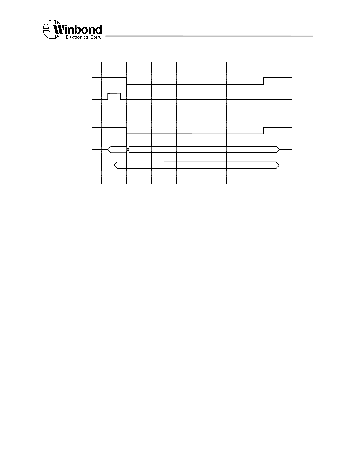
W90210F
FLASH Write timing
RCS_
ROMEN
ROM_OE_
ROM_RW_
MADDR<0:11>
MD<0:31>
or
MD<0:15>
or
MD<0:7>
47 Version 1.4, 10/8/97
The above information is the exclusive intellectual property of Winbond Electronics Corp. and shall not be disclosed, distributed or reproduced without permission from Winbond.
Page 48

W90210F
Appendix A. PA-RISC Multimedia Instruction Set
Halfword parallel add HADD
Format: HADD, cmplt r1,r2,t
0:5 5:10 11:15 27:3126
02
r2 r1 t
6 5 5 3 4 2 1 5
00
1
Purpose: To add multiple pairs of halfwords in parallel with optional saturation.
Description:The corresponding halfwords of GR r1 and GR r2 are added together in parallel. Optional
saturation is performed, which forces each halfword result to either the maximum or the
minimum value, if the result would have been out of the range of the target format. The
halfword results are placed in GR t.
The completer, cmplt, determines whether modular, signed-saturation, or unsignedsaturation arithmetic is performed. When no completer is specified (sat=3) modular
arithmetic is performed. The completer "ss" (sat=1) designates signed saturation. The
completer "us" (sat=0) indicates unsigned saturation. For signed saturation, all operands are
treated as signed numbers, and the results are signed numbers. For unsigned saturation, the
first operands, from GR r1, are treated as unsigned numbers, the second operands, from GR
r2, are treated as signed numbers, and the results are unsigned numbers.
Operation: GR[t]{0..15} ← GR[r1]{0..15} + GR[r2]{0..15};
GR[t]{16..31} ← GR[r1]{16..31} + GR[r2]{16..31};
switch (cmplt) {
case ss: if (max_signed_sat_L) /* sat=1 */
case ss: if (max_unsigned_sat_L) /* sat=0 */
default: /* sat=3 */
}
Exceptions: None.
sat
03
GR[t]{0..15} ← 0x7FFF;
else if (min_signed_sat_L)
GR[t]{0..15} ← 0x8000;
if (max_signed_sat_R)
GR[t]{16..31} ← 0x7FFF;
else if (min_signed_sat_R)
GR[t]{16..31} ← 0x8000;
break;
GR[t]{0..15} ← 0xFFFF;
else if (min_unsigned_sat_L)
GR[t]{0..15} ← 0x0000;
if (max_unsigned_sat_R)
GR[t]{16..31} ← 0xFFFF;
else if (min_unsigned_sat_R)
GR[t]{16..31} ← 0x0000;
break;
break;
48 Version 1.4, 10/8/97
The above information is the exclusive intellectual property of Winbond Electronics Corp. and shall not be disclosed, distributed or reproduced without permission from Winbond.
Page 49

W90210F
Halfword parallel subtract HSUB
Format: HSUB,cmplt r1,r2,t
0:5 5:10 11:15 27:3126
02
r2 r1 t
6 5 5 3 4 2 1 5
00
1
Purpose: To subtract multiple pairs of halfwords in parallel with optional saturation.
Description:The corresponding halfwords of GR r2 are subtracted from the halfwords of GR r1 in
parallel. Optional saturation is performed, which forces each halfword result to either the
maximum or the minimum value, if the result would have been out of the range of the target
format. The halfword results are placed in GR t.
The completer, cmplt, determines whether modular, signed-saturation, or unsignedsaturation arithmetic is performed. When no completer is specified (sat=3) modular
arithmetic is performed. The completer "ss" (sat=1) designates signed saturation. The
completer "us" (sat=0) indicates unsigned saturation. For signed saturation, all operands are
treated as signed numbers, and the results are signed numbers. For unsigned saturation, the
first operands, from GR r1, are treated as unsigned numbers, the second operands, from GR
r2, are treated as signed numbers, and the results are unsigned numbers.
Operation: GR[t]{0..15} ← (GR[r1]{0..15} + − GR[r2]{0..15} + 1);
GR[t]{16..31} ← (GR[r1]{16..31} + − GR[r2]{16..31} + 1);
switch (cmplt) {
case ss: if (max_signed_sat_L) /* sat=1 */
case ss: if (max_unsigned_sat_L) /* sat=0 */
default: /* sat=3 */
}
Exceptions: None.
sat
01
GR[t]{0..15} ← 0x7FFF;
else if (min_signed_sat_L)
GR[t]{0..15} ← 0x8000;
if (max_signed_sat_R)
GR[t]{16..31} ← 0x7FFF;
else if (min_signed_sat_R)
GR[t]{16..31} ← 0x8000;
break;
GR[t]{0..15} ← 0xFFFF;
else if (min_unsigned_sat_L)
GR[t]{0..15} ← 0x0000;
if (max_unsigned_sat_R)
GR[t]{16..31} ← 0xFFFF;
else if (min_unsigned_sat_R)
GR[t]{16..31} ← 0x0000;
break;
break;
49 Version 1.4, 10/8/97
The above information is the exclusive intellectual property of Winbond Electronics Corp. and shall not be disclosed, distributed or reproduced without permission from Winbond.
Page 50

W90210F
Halfword parallel average HAVE
Format: HAVE r1,r2,t
0:5 5:10 11:15 27:3126
02
r2 r1 t
6 5 5 3 6 1 5
00
1
Purpose: To average multiple pairs of halfwords in parallel.
Description:The corresponding halfwords of GR r1 and GR r2 are averaged in parallel. Both operands
are unsigned. The average is obtained by adding the corresponding halfwords, and shifting
the result right by one bit, to perform a divide by 2, with the halfword carry bit from the
addition shifted back into the leftmost position of each result. The halfword results are
placed in GR t.
Unbiased rounding is performed on the result of summation, to reduce the accumulation of
rounding errors with cascaded operations.
Operation:
cat(carry_L, sum{0..15}) ← GR[r1]{0..15} + GR[r2]{0..15}
cat(carry_R, sum{16..31}) ← GR[r1]{16..31} + GR[r2]{16..31}
new_lsb_L ← sum{14} | sum{15}; /* unbiased rounding */
new_lsb_R ← sum{30} | sum{31}; /* unbiased rounding */
GR[t]{0..15} ← cat(carry_L,sum{0..13}, new_lsb_L);
GR[t]{16..31} ← cat(carry_L,sum{16..29}, new_lsb_R);
Exceptions: None.
00b
50 Version 1.4, 10/8/97
The above information is the exclusive intellectual property of Winbond Electronics Corp. and shall not be disclosed, distributed or reproduced without permission from Winbond.
Page 51

W90210F
Halfword parallel shift left and add HSHLADD
Format: HSHLADD r1,k,r2,t or HSL1ADD r1,r2,t
HSL2ADD r1,r2,t
HSL3ADD r1,r2,t
0:5 5:10 11:15 27:3126
02
r2 r1 t
6 5 5 3 4 2 1 5
00
1
Purpose: To perform multiple pairs of halfword shift left and add operations in parallel with
saturation.
Description:Each halfword of GR r1 is shifted left by k bits, and then added to the corresponding
halfword of GR r2. Signed saturation is performed on the addition, which forces each
halfword result to either the maximum or the minimum value, if the result would have been
out of range. The halfword results are placed in GR t. The shift amount is either 1, 2, or 3,
and is encoded in the k field of the instruction.
All operands are treated as signed numbers, and the results are signed numbers. Signed
saturation is performed.
For this instruction, signed saturation is based both on the shift operation and the add
operation. That is, if the result of the shift operation is not representable in 16 bits, signed
saturation occurs. If GR r1 was positive, maximum saturation occurs. If GR r1 was negative,
minimum saturation occurs. If the result of the shift operation is representable in 16 bits,
then saturation is determined by the add operation in the normal fashion.
Operation: GR[t]{0..15} ← lshift(GR[r1]{0..15},k) + GR[r2]{0..15};
GR[t]{16..31} ← lshift(GR[r1]{16..31},k) + GR[r2]{16..31};
if (max_signed_sat_L)
GR[t]{0..15} ← 0x7FFF;
else if (min_signed_sat_L)
GR[t]{0..15} ← 0x8000;
if (max_signed_sat_R)
GR[t]{16..31} ← 0x7FFF;
else if (min_signed_sat_R)
GR[t]{16..31} ← 0x8000;
Exceptions: None.
07
k
51 Version 1.4, 10/8/97
The above information is the exclusive intellectual property of Winbond Electronics Corp. and shall not be disclosed, distributed or reproduced without permission from Winbond.
Page 52

W90210F
Halfword parallel shift right and add HSHRADD
Format: HSHRADD r1,k,r2,t or HSR1ADD r1,r2,t
HSR2ADD r1,r2,t
HSR3ADD r1,r2,t
0:5 5:10 11:15 27:3126
02
r2 r1 t
6 5 5 3 4 2 1 5
00
1
Purpose: To perform multiple pairs of halfword shift right and add operations in parallel with
saturation.
Description:Each halfword of GR r1 is shifted right by k bits, and then added to the corresponding
halfword of GR r2. The bits shifted into each halfword, from the left, are the same as the
sign bit for each halfword. Signed saturation is performed on the addition, which forces each
halfword result to either the maximum or the minimum value, if the result would have been
out of range. The halfword results are placed in GR t. The shift amount is either 1, 2, or 3,
and is encoded in the k field of the instruction.
All operands are treated as signed numbers, and the results are signed numbers. Signed
saturation is performed.
Operation: GR[t]{0..15} ← arshift(GR[r1]{0..15},k) + GR[r2]{0..15};
GR[t]{16..31} ← arshift(GR[r1]{16..31},k) + GR[r2]{16..31};
if (max_signed_sat_L)
GR[t]{0..15} ← 0x7FFF;
else if (min_signed_sat_L)
GR[t]{0..15} ← 0x8000;
if (max_signed_sat_R)
GR[t]{16..31} ← 0x7FFF;
else if (min_signed_sat_R)
GR[t]{16..31} ← 0x8000;
Exceptions: None.
05
k
52 Version 1.4, 10/8/97
The above information is the exclusive intellectual property of Winbond Electronics Corp. and shall not be disclosed, distributed or reproduced without permission from Winbond.
Page 53

W90210F
Appendix B. Diagnostic Instructions
HALT
Format: HALT
0:5 5:10 11:15 27:312621:25
05
6 5 5 52 3 1 5
Purpose: To halt instruction pipeline and entry ICE single-step mode.
Description: The HALT instruction clears instruction pipeline. Any unfinished bus cycle and internal I/D-
Operation: Enforce CPU clear pipeline and entry single-step mode;
Note: This instruction can be executed by code running at any privileged level. (different from other
- - -
- -
cache operation will be cleared before CPU entering single-step mode.
diagnostic instr.)
10
-
53 Version 1.4, 10/8/97
The above information is the exclusive intellectual property of Winbond Electronics Corp. and shall not be disclosed, distributed or reproduced without permission from Winbond.
Page 54

W90210F
Move to AIR MTAIR
Format: MTAIR r,t
0:5 5:10 11:15 27:312621:25
05
t r -
- -
6 5 5 52 3 1 5
Purpose: To copy value into a specified AIR from a general register.
Description: If the AIR[t] is existed, the contents of GR[r] is copied into AIR[t]. If AIR[t] has n bits where
n<=32, the least significant n bits of GR[r] are moved into AIR[t].
Operation: if(t > 6)
else if(priv != 0)
else
Exception: Privilege instruction trap.
Restriction: This instruction can be executed only by code running at the most privileged level.
Notes: AIR[0]: Internal configuration register
AIR[1]: PSW register (default: 32'h0)
AIR[2]: TMR (timer register)
AIR[3]: Non-cacheable Offset register
AIR[4]: Non-cacheable Mask register
AIR[5]: Write-Through Offset register
AIR[6]: Write-Through Mask register
AIR[7]: PCO register (program counter)
00
-
undefined operation;
privilege instruction trap;
AIR[t] <-- GR[r];
- bit31: Internal I-Cache enable (0/1- disable/enable)
- bit30: Internal D-Cache enable (0/1- disable/enable)
- bit29: Burst write enable (0/1- disable/enable)
- bit28: Default endian bit (0/1- big/little endian)
- bit27: Trap step mode enable (0/1- disable/enable)
- bit26: reserved
- bit25: reserved
- bit24: Enter Sleep state
- bit23: Multiplier wait state (0/1- 0/1 wait state)
- bit22: Freeze 1st 1K of I-Cache (0/1- disable/enable)
- bit21: Freeze 2nd 1K of I-Cache (0/1- disable/enable)
- bit20: Freeze 3rd 1K of I-Cache (0/1- disable/enable)
- bit19: Freeze 4th 1K of I-Cache (0/1- disable/enable)
(default: 13'b0)
54 Version 1.4, 10/8/97
The above information is the exclusive intellectual property of Winbond Electronics Corp. and shall not be disclosed, distributed or reproduced without permission from Winbond.
Page 55

W90210F
Move from AIR MFAIR
Format: MFAIR r,t
0:5 5:10 11:15 27:312621:25
05
r - t
- -
6 5 5 52 3 1 5
Purpose: To copy value into a general register from AIR register.
Description: If the AIR[r] is existed, the contents of AIR[r] is copied into GR[t]. If AIR[r] has only n bits
where n<=32, the least significant n bits of AIR[r] are moved into GR[t] and the others are
zero.
Operation: if(t > 6)
else if(priv != 0)
else
Exception: Privilege instruction trap.
Restriction: This instruction can be executed only by code running at the most privileged level.
Notes: AIR[0]: Internal configuration register
AIR[1]: PSW register
AIR[2]: TCP (timer comparator register)
AIR[3]: Non-cacheable Offset register
AIR[4]: Non-cacheable Mask register
AIR[5]: Write-Through Offset register
AIR[6]: Write-Through Mask register
AIR[7]: PCO register (program counter)
01
-
undefined operation;
privilege instruction trap;
GR[t] <-- AIR[r];
55 Version 1.4, 10/8/97
The above information is the exclusive intellectual property of Winbond Electronics Corp. and shall not be disclosed, distributed or reproduced without permission from Winbond.
Page 56

W90210F
Move to Itag MTITAG
Format: MTITAGb
0:5 5:10 11:15 27:312621:25
05
b - -
- -
08
-
6 5 5 52 3 1 5
Purpose: To copy a value into Itag from a general register.
Description: GR r is copied into a specified entry of Itag.
Operation: entry <-- GR[b][24:31];
Itag[entry][0:20] <-- GR[b][0:20];
Exception: Privilege instruction trap.
Restriction: This instruction can be executed only by code running at the most privileged level.
Note: Itag[entry][0:19]: tag field.
Itag[entry][20]: valid bit.
Move from Itag
Format: MFITAGb,t
0:5 5:10 11:15 27:312621:25
05
b - t
- -
6 5 5 52 3 1 5
Purpose: To copy a value into general register from Itag.
Description: The content of a specified Itag_entry is copied into GR t.
Operation: way <-- AIR[0][26];
entry <-- {way, GR[b][25:31]};
GR[t][0:21] <-- Itag[entry][0:21]
Exception: Privilege instruction trap.
Restriction: This instruction can be executed only by code running at the most privileged level.
09
-
56 Version 1.4, 10/8/97
The above information is the exclusive intellectual property of Winbond Electronics Corp. and shall not be disclosed, distributed or reproduced without permission from Winbond.
Page 57

W90210F
Move to I-Cache MTICAH
Format: MTICAHr,b
0:5 5:10 11:15 27:312621:25
05
b r -
- -
6 5 5 52 3 1 5
Purpose: To copy a value into I-Cache from a general register.
Description: GR r is copied into specified I-Cache entry.
Operation: entry <-- GR[b][21:27];
word <-- GR[b][28:29];
way <-- AIR[0][26];
I-Cache[way, entry, word] <-- GR[r];
Exception: Privilege instruction trap.
Restriction: This instruction can be executed only by code running at the most privileged level.
0A
-
57 Version 1.4, 10/8/97
The above information is the exclusive intellectual property of Winbond Electronics Corp. and shall not be disclosed, distributed or reproduced without permission from Winbond.
Page 58

W90210F
Move from I-Cache MFICAH
Format: MFICAHb,t
0:5 5:10 11:15 27:312621:25
05
b - t
- -
6 5 5 52 3 1 5
Purpose: To copy a value into general register from I-Cache.
Description: A word of specified I-Cache entry is copied into GR t.
Operation: entry <-- GR[b][21:27];
word <-- GR[b][28:29];
way <-- AIR[0][26];
GR[t] <-- I-Cache[way, entry, word];
Exception: Privilege instruction trap.
Restriction: This instruction can be executed only by code running at the most privileged level.
0B
-
58 Version 1.4, 10/8/97
The above information is the exclusive intellectual property of Winbond Electronics Corp. and shall not be disclosed, distributed or reproduced without permission from Winbond.
Page 59

W90210F
Move to Dtag MTDTAG
Format: MTDTAG b
0:5 5:10 11:15 27:312621:25
05
b - -
- -
6 5 5 52 3 1 5
Purpose: To copy a value into Dtag from a general register.
Description: GR r is copied into a specified entry of Dtag.
Operation: entry <-- GR[b][25:31];
Itag[entry][0:22] <-- GR[b][0:22];
Exception: Privilege instruction trap.
Restriction: This instruction can be executed only by code running at the most privileged level.
Note: Itag[entry][0:21]: tag field.
Itag[entry][22]: valid bit.
Itag[entry][23]: dirty bit.
0C
-
59 Version 1.4, 10/8/97
The above information is the exclusive intellectual property of Winbond Electronics Corp. and shall not be disclosed, distributed or reproduced without permission from Winbond.
Page 60

W90210F
Move from Dtag MFDTAG
Format: MFDTAG b,t
0:5 5:10 11:15 27:312621:25
05
b - t
- -
6 5 5 52 3 1 5
Purpose: To copy a value into general register from Dtag.
Description: The content of a specified Dtag_entry is copied into GR t.
Operation: entry <-- GR[b][25:31];
GR[t][0:22] <-- Itag[entry][0:22]
Exception: Privilege instruction trap.
Restriction: This instruction can be executed only by code running at the most privileged level.
0D
-
60 Version 1.4, 10/8/97
The above information is the exclusive intellectual property of Winbond Electronics Corp. and shall not be disclosed, distributed or reproduced without permission from Winbond.
Page 61

W90210F
Move to D-Cache MTDTAG
Format: MTDCAH r,b
0:5 5:10 11:15 27:312621:25
05
b r -
- -
6 5 5 52 3 1 5
Purpose: To copy a value into D-Cache from a general register.
Description: GR r is copied into specified D-Cache entry.
Operation: entry <-- GR[b][21:27];
word <-- GR[b][28:29];
I-Cache[entry, word] <-- GR[r];
Exception: Privilege instruction trap.
Restriction: This instruction can be executed only by code running at the most privileged level.
0E
-
61 Version 1.4, 10/8/97
The above information is the exclusive intellectual property of Winbond Electronics Corp. and shall not be disclosed, distributed or reproduced without permission from Winbond.
Page 62

W90210F
Move from D-Cache MFDCAH
Format: MFDCAH b,t
0:5 5:10 11:15 27:312621:25
05
b - t
- -
6 5 5 52 3 1 5
Purpose: To copy a value into general register from D-Cache.
Description: A word of specified D-Cache entry is copied into GR t.
Operation: entry <-- GR[b][21:27];
word <-- GR[b][28:29];
GR[t] <-- I-Cache[entry, word];
Exception: Privilege instruction trap.
Restriction: This instruction can be executed only by code running at the most privileged level.
0F
-
62 Version 1.4, 10/8/97
The above information is the exclusive intellectual property of Winbond Electronics Corp. and shall not be disclosed, distributed or reproduced without permission from Winbond.
Page 63

W90210F
Halfword Parallel Multiply HPMPY
Format: HPMPY,cmplt r1,r2,t
0:5 6:10 11:15 27:312621:25
05
r2 r1 t
6 5 5 52 2 1 5
Purpose: To multiply multiple pairs of halfwords in parallel with optional saturation.
Description:The corresponding halfwords of GR r1 and GR r2 are multiplied together in parallel. Optional
saturation is performed, which forces each halfword result to either the maximum or the
minimum value, if the result would have been out of the range of the target format. The halfword
results are placed in GR t.
The completer, cmplt, determines whether modular, signed-saturation, or unsigned-saturation
multiplication is performed. When no completer is specified modular arithmetic is performed.
The completer "ss" designates signed saturation. The completer "us" indicates unsigned
saturation. For signed saturation, all operands are treated as signed numbers, and the results are
signed numbers. For unsigned saturation, the first operands, from GR r1, are treated as unsigned
numbers, the second operands, from GR r2, are treated as signed numbers, and the results are
unsigned numbers.
Operation:
switch(cmplt) {
case u(g=0, sat=00, unsigned multiplication) {
case s(g=1, sat=00, signed multiplication) {
case us(g=0, sat=01, unsigned multiplication with saturation) {
: if (unsigned_sat_L) GR[t]{0..15} ← 0xFFFF;
case ss(g=1, sat=01, signed multiplication with saturation) {
: if (pos_signed_sat_L) GR[t]{0..15} ← 0x7FFF;
default:
}
sat
12
-
g
1
0
GR[t]{0..15} ← zero_ext(GR[r1]{0..15}) × zero_ext(GR[r2]{0..15})
GR[t]{16..31} ← zero_ext(GR[r1]{16..31}) × zero_ext(GR[r2]{16..31})
}
GR[t]{0..15} ← sign_ext(GR[r1]{0..15}) × sign_ext(GR[r2]{0..15})
GR[t]{16..31} ← sign_ext(GR[r1]{16..31}) × sign_ext(GR[r2]{16..31})
}
GR[t]{0..15} ← zero_ext(GR[r1]{0..15}) × zero_ext(GR[r2]{0..15})
GR[t]{16..31} ← zero_ext(GR[r1]{16..31}) × zero_ext(GR[r2]{16..31})
if (unsigned_sat_R) GR[t]{16..31} ← 0xFFFF;
break;
}
GR[t]{0..15} ← sign_ext(GR[r1]{0..15}) × sign_ext(GR[r2]{0..15})
GR[t]{16..31} ← sign_ext(GR[r1]{16..31}) × sign_ext(GR[r2]{16..31})
else if (neg_signed_sat_L) GR[t]{0..15} ← 0x8000;
if (pos_signed_sat_R) GR[t]{16..31} ← 0x7FFF;
else if (neg_signed_sat_R) GR[t]{16..31} ← 0x8000;
break;
}
break;
Exception: None
Restriction: Winbond defined instruction for W90210F.
63 Version 1.4, 10/8/97
The above information is the exclusive intellectual property of Winbond Electronics Corp. and shall not be disclosed, distributed or reproduced without permission from Winbond.
Page 64

W90210F
Halfword Multiply HMPY
Format: HMPY, cmplt r1,r2,t
0:5 6:10 11:15 27:312621:25
05
r2 r1 t
6 5 5 52 1 5
c
2
Purpose: To multiply corresponding halfwords of two registers.
Description:The corresponding 16-bit halfwords of GR r1 and GR r2 are interpreted as signed or unsigned
16-bit integers and are arithmetically multiplied together. The 32-bit result is placed in GR t.
The cmplt completer is specified by the g and the c bits in the instruction.
Operation:
switch(cmplt) {
case uhh (g=0, c=00, unsigned multiplication) {
GR[t]{0..31} ← zero_ext(GR[r1]{0..15}) × zero_ext(GR[r2]{0..15})
break;
}
case shh (g=1, c=00, signed multiplication) {
GR[t]{0..31} ← sign_ext(GR[r1]{0..15}) × sign_ext(GR[r2]{0..15})
break;
}
case uhl (g=0, c=01, unsigned multiplication) {
GR[t]{0..31} ← zero_ext(GR[r1]{0..15}) × zero_ext(GR[r2]{16:31})
break;
}
case shl (g=1, c=01, signed multiplication) {
GR[t]{0..31} ← sign_ext(GR[r1]{0..15}) × sign_ext(GR[r2]{16:31}
break;
}
case ulh (g=0, c=10, unsigned multiplication) {
GR[t]{0..31} ← zero_ext(GR[r1]{16:31}) × zero_ext(GR[r2]{0..15})
break;
}
case slh (g=1, c=10, signed multiplication) {
GR[t]{0..31} ← sign_ext(GR[r1]{16:31}) × sign_ext(GR[r2]{0..15})
break;
}
case ull (g=0, c=11, unsigned multiplication) {
GR[t]{0..31} ← zero_ext(GR[r1]{16:31}) × zero_ext(GR[r2]{16:31})
break;
}
case sll (g=1, c=11, signed multiplication) {
GR[t]{0..31} ← sign_ext(GR[r1]{16:31}) × sign_ext(GR[r2]{16:31})
break;
}
}
12
-
g
1
1
Exception: None
Restriction: Winbond defined instruction for W90210F.
64 Version 1.4, 10/8/97
The above information is the exclusive intellectual property of Winbond Electronics Corp. and shall not be disclosed, distributed or reproduced without permission from Winbond.
Page 65

W90210F
Halfword Absolute and Add HABSADD
Format: HABSADD, cmplt r1, r2,t
0:5 6:10 11:15 27:312621:25
05
r2 r1 t
6 5 5 53 1 5
Purpose: To add multiple pairs of halfwords in parallel with absolute and optional saturation.
Description:The corresponding halfwords of GR r1 are added with the halfwords of absoluted GR r2 in
parallel. Optional saturation is performed, which forces each halfword result to either the
maximum or the minimum value, if the result would have been out of the range of the target
format. The halfword results are placed in GR t.
The completer, cmplt, determines whether modular, signed-saturation, or unsigned-saturation
arithmetic is performed. When no completer is specified (sat=3) modular arithmetic is
performed. The completer "ss" (sat=1) designates signed saturation. The completer "us" (sat=0)
indicates unsigned saturation. For signed saturation, all operands are treated as signed numbers,
and the results are signed numbers. For unsigned saturation, the first operands, from GR r1, are
treated as unsigned numbers, the second operands, from GR r2, are treated as signed numbers,
and the results are unsigned numbers.
Operation:
if (GR[r2]{0} == 1) GR[t]{0..15} ← GR[r1]{0..15} + (~GR[r2]{0..15} + 1);
else GR[t]{0..15} ← GR[r1]{0..15} + GR[r2]{0..15} ;
if(GR[r2]{16} == 1) GR[t]{16..31} ← GR[r1]{16:31} + (~GR[r2]{16..31} + 1);
else GR[t]{16..31} ← GR[r1]{16:31} + GR[r2]{16..31};
switch (cmplt) {
16:17 18:20
13
sat
2
-
-
case ss: if(max_signed_sat_L) /* sat=1*/
GR[t]{0:15} ← 0x7FFF;
else if (min_signed_sat_L)
GR[t]{0:15} ← 0x8000;
if(max_signed_sat_R)
GR[t]{16:31} ← 0x7FFF;
else if (min_signed_sat_R)
GR[t]{16:31} ← 0x8000;
break;
case us: if(max_unsigned_sat_L) /*sat=0*/
GR[t]{0:15} ← 0xFFFF;
else if (min_unsigned_sat_L)
GR[t]{0:15} ← 0x0000;
if(max_unsigned_sat_R)
GR[t]{16:31} ← 0xFFFF;
else if (min_unsigned_sat_R)
GR[t]{16:31} ← 0x0000;
break;
default: /*sat=3*/
break;
}
Exceptions: None
Restriction: Winbond defined instruction for W90210F.
65 Version 1.4, 10/8/97
The above information is the exclusive intellectual property of Winbond Electronics Corp. and shall not be disclosed, distributed or reproduced without permission from Winbond.
Page 66

W90210F
Load Halfword Unpacked LDHU
Format: LDHU, cmplt d(s,b),t
0:5 5:10 11:15 27:312621:25
05
6 5 5 52 3 1 5
b im5 t
Purpose: To load a halfword and unpack into a general register.
Description: The aligned halfword at the effective address is uppacked into two bytes, zero-extended to
Operation: switch (cmplt) {
GR[t] ← cat(zero_ext(mem_load(offset,0,7),16), zero_ext(mem_load(offset,8,15),16))
Exception: None.
Restriction: Winbond defined instruction for W90210F.
s
-14a
1
m
two halfwords and loaded into GR t. The completer, cmplt, determines if the offset is the
base register, b, or the base register plus the short displacement, d. The displacement is
encoded in the im5 field. The completer, encoded in the a and m fields of the instruction,
also specifies base register modification. If base register modification is specified and b=t,
the value loaded is the unpacked halfwords at the effective address.
case MB: offset ← GR[b] + low_sign_ext(im5,5); /* a=1,m=1 */
GR[b] ← GR[b] + low_sign_ext(im5,5);
break;
case MA: offset ← GR[b]; /* a=0,m=1 */
GR[b] ← GR[b] + low_sign_ext(im5,5);
break;
default: offset ← GR[b] + low_sign_ext(im5,5); /* m=0 */
break;
}
66 Version 1.4, 10/8/97
The above information is the exclusive intellectual property of Winbond Electronics Corp. and shall not be disclosed, distributed or reproduced without permission from Winbond.
Page 67

W90210F
CORPORATE HEADQUARTERS: INFORMATION CONTACTS:
NO. 4, Creation Rd. III Rongken Yang
Science-Based Industrial Park Special Product Design Dept. I
Hsinchu, Taiwan, R.O.C. TEL: 886-35-792632
TEL: 886-35-770066 E-mail: [email protected]
FAX: 886-35-792647
Note: All data and specifications are subject to change without notice.
67 Version 1.4, 10/8/97
The above information is the exclusive intellectual property of Winbond Electronics Corp. and shall not be disclosed, distributed or reproduced without permission from Winbond.
 Loading...