

Page 1

W83194R-39/-39A
100MHZ 3-DIMM CLOCK
1.0 GENERAL DESCRIPTION
The W83194R-39/-39A is a Clock Synthesizer which provides all clocks required for high-speed RISC
or CISC microprocessor such as Intel Pentium II. W83194R-39 provides eight different frequency of
CPU and PCI clocks and W83194R-39A provides sixteen CPU/PCI frequencies which are externally
selectable with smooth transitions. W83194R-39/-39A also provides 13 SDRAM clocks controlled by
the none-delay buffer_in pin.
The W83194R-39/-39A accepts a 14.318 MHz reference crystal as its input and runs on a 3.3V
supply. Spread spectrum built in at ¡Ó0.5% or ¡Ó0.25% to reduce EMI. Programmable stopping
individual clock outputs and frequency selection through I2C interface. The device meets the
Pentium power-up stabilization, which requires CPU and PCI clocks be stable within 2 ms after
power-up. It is not recommend to use the dual function pin for the slots(ISA, PCI, CPU, DIMM). The
add on cards may have a pull up or pull down.
High drive six PCI and thirteen SDRAM CLOCK outputs typically provide greater than 1 V /ns slew
rate into 30 pF loads. Two CPU CLOCK outputs typically provide better than 1 V /ns slew rate into 20
pF loads as maintaining 50¡Ó 5% duty cycle. The fixed frequency outputs as REF, 24MHz, and 48
MHz provide better than 0.5V /ns slew rate.
2.0 PRODUCT FEATURES
• Supports Pentium II CPU with I2C.
• 2 CPU clocks (one free-running CPU clock)
• 13 SDRAM clocks for 3 DIMs
• 6 PCI synchronous clocks
• One IOAPIC clock for multiprocessor support
• Optional single or mixed supply:
(Vddq1=Vddq2 = Vddq3 = Vddq4 = VddL1 =VddL2= 3.3V) or (Vddq1= Vddq2 = Vddq3=Vddq4 =
3.3V, VddL1 = VdqL2 = 2.5V)
• < 250ps skew among CPU and SDRAM clocks
• < 250ps skew among PCI clocks
• < 5ns propagation delay SDRAM from buffer input
• Skew from CPU(earlier) to PCI clock -1 to 4ns, center 2.6ns.
• Smooth frequency switch with selections from 50 MHz to 133 MHz CPU
• I2C 2-Wire serial interface and I2C read back
Publication Release Date: May 1998
- 1 - Revision 0.20
Page 2
W83194R-39/-39A
W83194R-39
W83194R-39A
• ¡Ó0.25% or ¡Ó0.5% spread spectrum function to reduce EMI
• Programmable registers to enable/stop each output and select modes
(mode as Tri-state or Normal )
• 2ms power up clock stable time
• MODE pin for power Management
• One 48 MHz for USB & one 24 MHz for super I/O
• 48-pin SSOP package
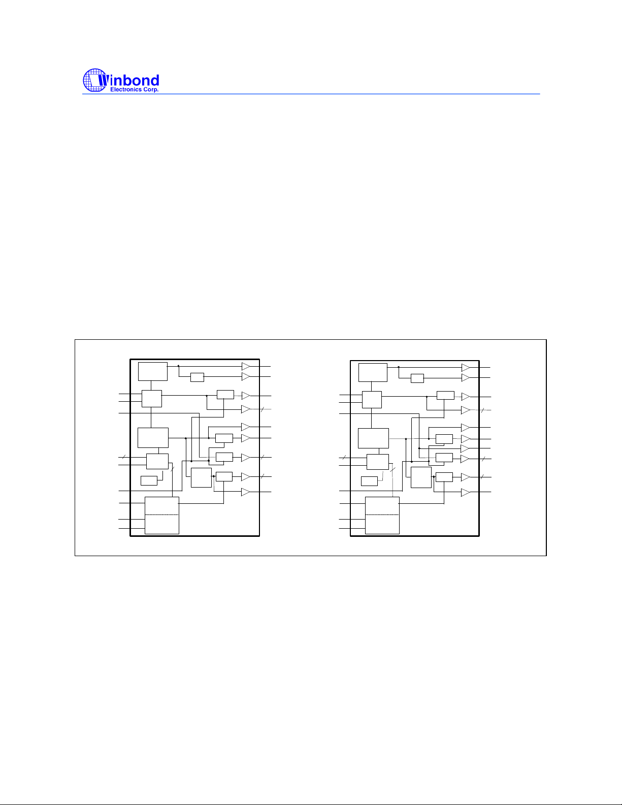
3.0 BLOCK DIAGRAM
PRELIMINARY
BUFFER IN
CPU_STOP#
PCI_STOP#
Xin
Xout
FS(0:2)*
MODE*
SDATA*
SDCLK*
PLL2
~
XTAL
OSC
6
PLL1
Spread
Spectrum
3
LATCH
~
POR
Control
Logic
Config.
Reg.
1/2
STOP
STOP
STOP
4
PCI
STOP
Clock
Divider
48MHz
24MHz
IOAPIC
REF(0:1)
2
CPUCLK_F
CPUCLK1
SDRAM(0:12)
13
PCICLK(0:4)
5
PCICLK_F
Xin
Xout
BUFFER IN
FS(0:3)*
MODE*
CPU_STOP#
PCI_STOP#
SDATA*
SDCLK*
PLL2
~
XTAL
OSC
6
PLL1
Spread
Spectrum
4
LATCH
~
POR
Control
Logic
Config.
Reg.
1/2
STOP
STOP
STOP
4
PCI
STOP
Clock
Divider
48MHz
24MHz
IOAPIC
REF(0:1)
2
CPUCLK_F
CPUCLK1
SDRAM12
SDRAM(0:11)
12
PCICLK(0:4)
5
PCICLK_F
Publication Release Date: May 1998
- 2 - Revision 0.20
Page 3
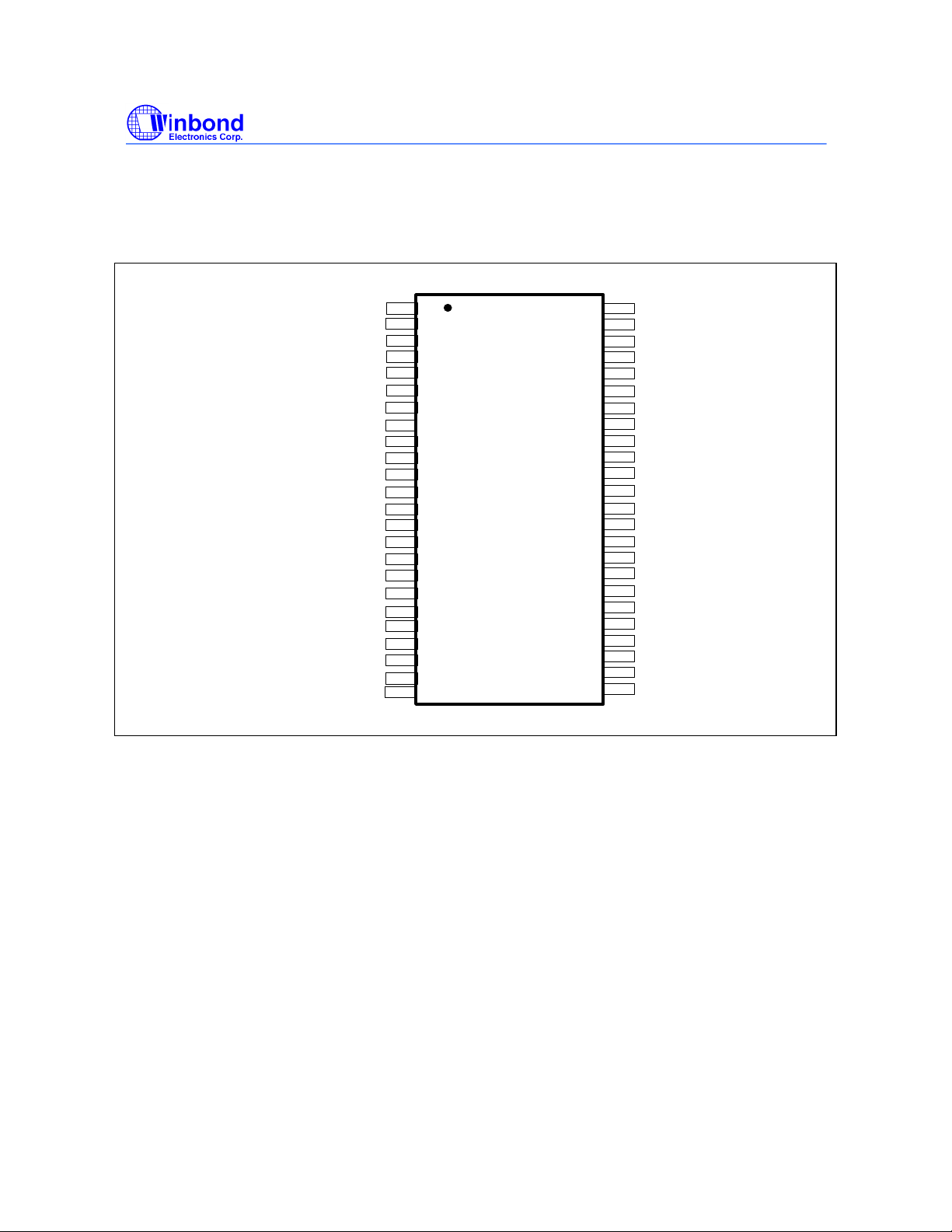
4.0 PIN CONFIGURATION
W83194R-39/-39A
PRELIMINARY
(W83194R-39A )
Vddq1
PCI_STOP#/REF0
Vss
Xin
Xout
Vddq2
PCICLK_F/MODE*
PCICLK0/FS3*
Vss
PCICLK1
PCICLK2
PCICLK3
PCICLK4
Vddq2
BUFFER IN
Vss
SDRAM11
SDRAM10
Vddq3
SDRAM 9
SDRAM 8
Vss
SDATA
SDCLK
1
2
3
4
5
6
7
8
9
10
11
12
13
14
15
16
17
18
19
20
21
22
23
24
48
47
46
45
44
43
42
41
40
39
38
37
36
35
34
33
32
31
30
29
28
27
26
25
VddL1
IOAPIC
REF1/FS2*
Vss
CPUCLK_F
CPUCLK1
VddL2
CPU_STOP#
SDRAM12
Vss
SDRAM 0
SDRAM 1
Vddq3
SDRAM 2
SDRAM 3
Vss
SDRAM 4
SDRAM 5
Vddq3
SDRAM 6
SDRAM 7
Vddq4
48MHz/FS0*
24MHz/FS1*
5.0 PIN DESCRIPTION
IN - Input
OUT - Output
I/O - Bi-directional Pin
# - Active Low
* - Internal 250kΩ pull-up
Publication Release Date: May 1998
- 3 - Revision 0.20
Page 4
W83194R-39/-39A
PRELIMINARY
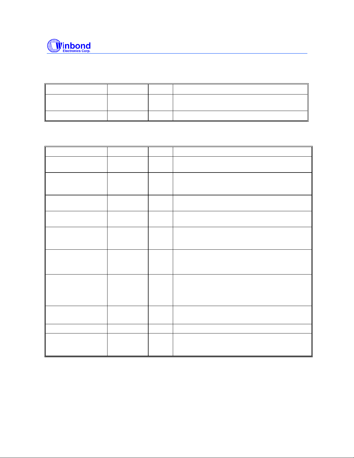
5.1 Crystal I/O
SYMBOL PIN I/O FUNCTION
Xin 4 IN Crystal input with internal loading capacitors and
feedback resistors.
Xout 5 OUT Crystal output at 14.318MHz nominally.
5.2 CPU, SDRAM, PCI, IOAPIC Clock Outputs
SYMBOL PIN I/O FUNCTION
CPUCLK_F 44 OUT Free running CPU clock. Not affected by
CPU_STOP#
CPUCLK1 43 OUT Low skew (< 250ps) clock outputs for host
frequencies such as CPU, Chipset and Cache.
Powered by VddL2. Low if CPU_STOP# is low.
CPU_STOP# 41 IN This asynchronous input halts CPUCLK1,IOAPIC &
SDRAM(0:12) at logic
IOAPIC 47 OUT High drive buffered output of the crystal, and is
powered by VddL1.
SDRAM [ 0:12] 17,18,20,21,28
,29,31,32,34,
35,37,38,40
PCICLK_F/
*MODE
PCICLK0/*FS3
(W83194R-39A)
PCICLK [ 0:4 ]
(W83194R-39)
BUFFER IN 15 IN Inputs to fanout for SDRAM outputs.
SDRAM [ 0: 11 ] 17,18,20,21,
7 I/O Free running PCI clock during normal operation.
8 I/O Low skew (< 250ps) PCI clock outputs.
8,10,11,12,13 OUT Low skew (< 250ps) PCI clock outputs. Synchronous
28,29,31,32,
34,35,37,38
OUT SDRAM clock outputs. Fanout buffer outputs from
BUFFER IN pin.(Controlled by chipset)
Latched Input. Mode=1, Pin 2 is REF0; Mode=0,
Pin2 is PCI_STOP#
Latched input for FS3 at initial power up for H/W
selecting the output frequency of CPU, SDRAM and
PCI clocks.
to CPU clocks with 1-48ns skew(CPU early).
O Synchronous DRAM DIMs clocks which have the
same frequency as CPU clocks
“0”
level when driven low.
Publication Release Date: May 1998
- 4 - Revision 0.20
Page 5
W83194R-39/-39A
PRELIMINARY
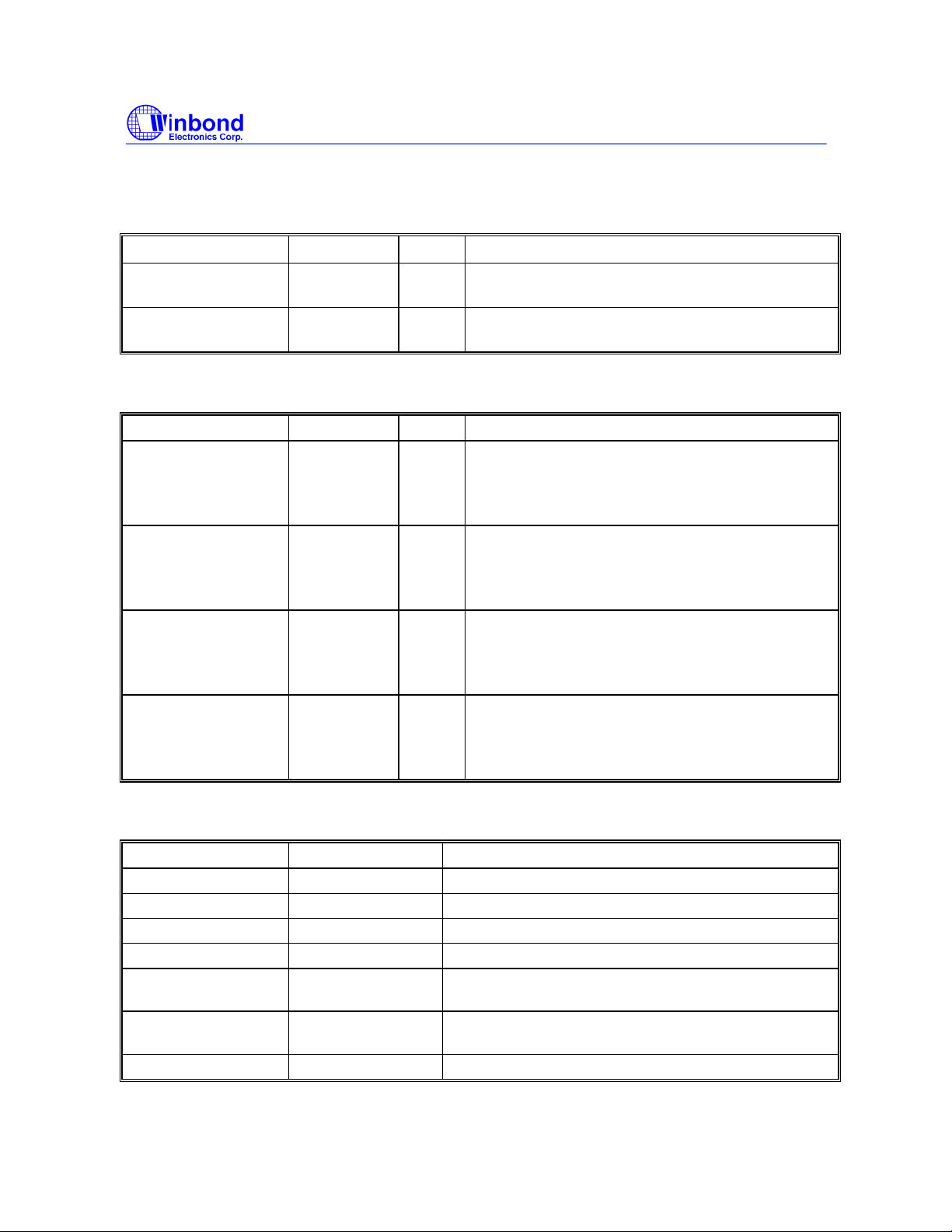
5.3 I2C Control Interface
SYMBOL PIN I/O FUNCTION
SDATA 23 I/O Serial data of I2C 2-wire control interface with internal
pull-up resistor.
SDCLK 24 IN Serial clock of I2C 2-wire control interface with
internal pull-up resistor.
5.4 Fixed Frequency Outputs
SYMBOL PIN I/O FUNCTION
REF0 / PCI_STOP# 2 I/O 14.318MHz reference clock. This REF output is the
stronger buffer for ISA bus loads.
Halt PCICLK(0:4) clocks at logic 0 level, when input
low (In mobile mode. MODE=0)
REF1 / *FS2 46 I/O 14.318MHz reference clock.
Latched input for FS2 at initial power up for H/W
selecting the output frequency of CPU, SDRAM and
PCI clocks.
24MHz / *FS1 25 I/O 24MHz output clock.
Latched input for FS1 at initial power up for H/W
selecting the output frequency of CPU, SDRAM and
PCI clocks.
48MHz / *FS0 26 I/O 48MHz output for USB during normal operation.
Latched input for FS0 at initial power up for H/W
selecting the output frequency of CPU, SDRAM and
PCI clocks.
5.5 Power Pins
SYMBOL PIN FUNCTION
Vddq1 1 Power supply for Ref [0:1] crystal and core logic.
VddL1 48 Power supply for IOAPIC output, either 2.5V or 3.3V.
VddL2 42 Power supply for CPUCLK[0:3], either 2.5V or 3.3V.
Vddq2 6, 14 Power supply for PCICLK_F, PCICLK[0:4], 3.3V.
Vddq3 19, 30, 36 Power supply for SDRAM[0:12], and CPU PLL core,
nominal 3.3V.
Vddq4 27 Power for 24 & 48MHz output buffers and fixed PLL
core.
Vss 3,9,16,22,33,39,45 Circuit Ground.
Publication Release Date: May 1998
- 5 - Revision 0.20
Page 6
W83194R-39/-39A
PRELIMINARY
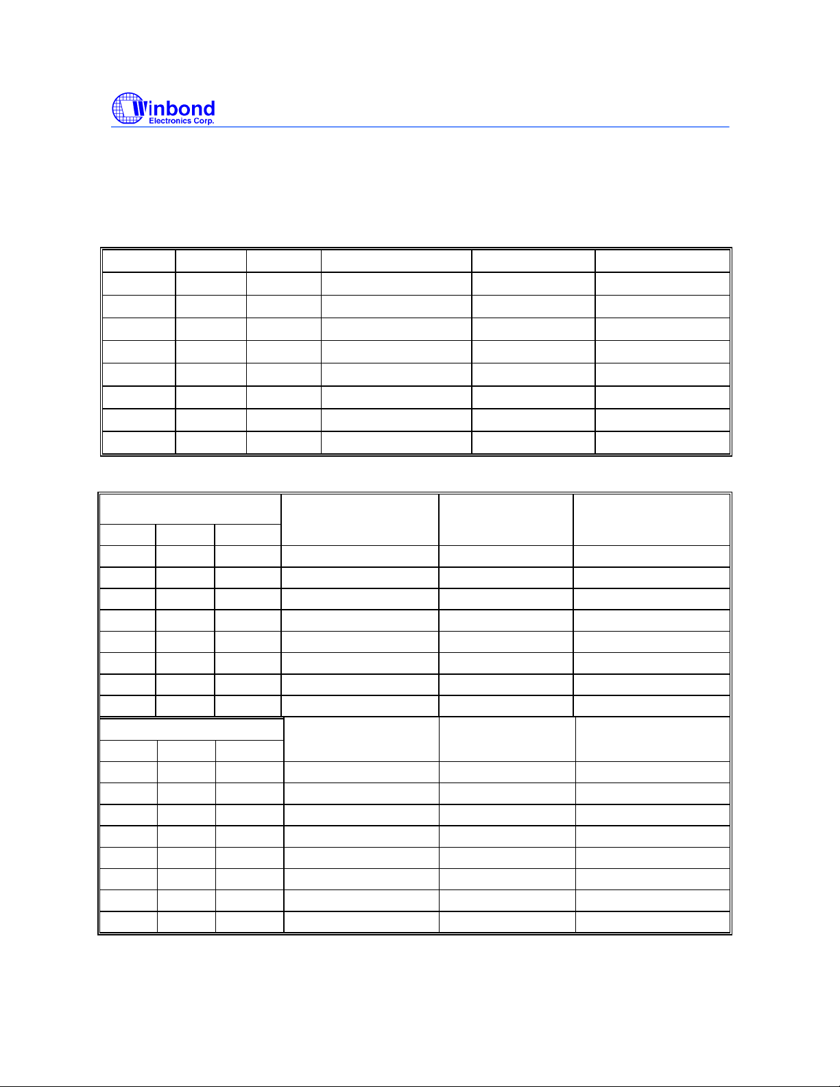
6.0 FREQUENCY SELECTION
6.1 Frequency table of W83194R-39
FS2 FS1 FS0 CPU,SDRAM (MHz) PCI (MHz) REF,IOAPIC (MHz)
0 0 0 50 25(CPU/2) 14.318
0 0 1 75 37.5(CPU/2) 14.318
0 1 0 83.3 41.65(CPU/2) 14.318
0 1 1 66.8 33.4(CPU/2) 14.318
1 0 0 103 34.3(CPU/3) 14.318
1 0 1 112 37.33(CPU/3) 14.318
1 1 0 133 33.25(CPU/4) 14.318
1 1 1 100.2 33.3(CPU/3) 14.318
6.2 Frequency table of W83194R-39A
FS3=0 CPU,SDRAM (MHz) PCI (MHz) REF,IOAPIC
FS2 FS1 FS0 (MHz)
0 0 0 124 41.33(CPU/3) 14.318
0 0 1 75 37.5(CPU/2) 14.318
0 1 0 83.3 41.65(CPU/2) 14.318
0 1 1 66.8 33.4(CPU/2) 14.318
1 0 0 103 34.3(CPU/3) 14.318
1 0 1 112 37.33(CPU/3) 14.318
1 1 0 133 44.33(CPU/3) 14.318
1 1 1 100.3 33.3(CPU/3) 14.318
FS3=1 CPU,SDRAM (MHz) PCI (MHz) REF,IOAPIC
FS2 FS1 FS0 (MHz)
0 0 0 120 40.00(CPU/3) 14.318
0 0 1 115 38.33(CPU/3) 14.318
0 1 0 110 36.67(CPU/3) 14.318
0 1 1 105 35.00(CPU/3) 14.318
1 0 0 140 35.00(CPU/4) 14.318
1 0 1 150 37.50(CPU/4) 14.318
1 1 0 124 31.00(CPU/4) 14.318
1 1 1 133 33.25(CPU/4) 14.318
Publication Release Date: May 1998
- 6 - Revision 0.20
Page 7
W83194R-39/-39A
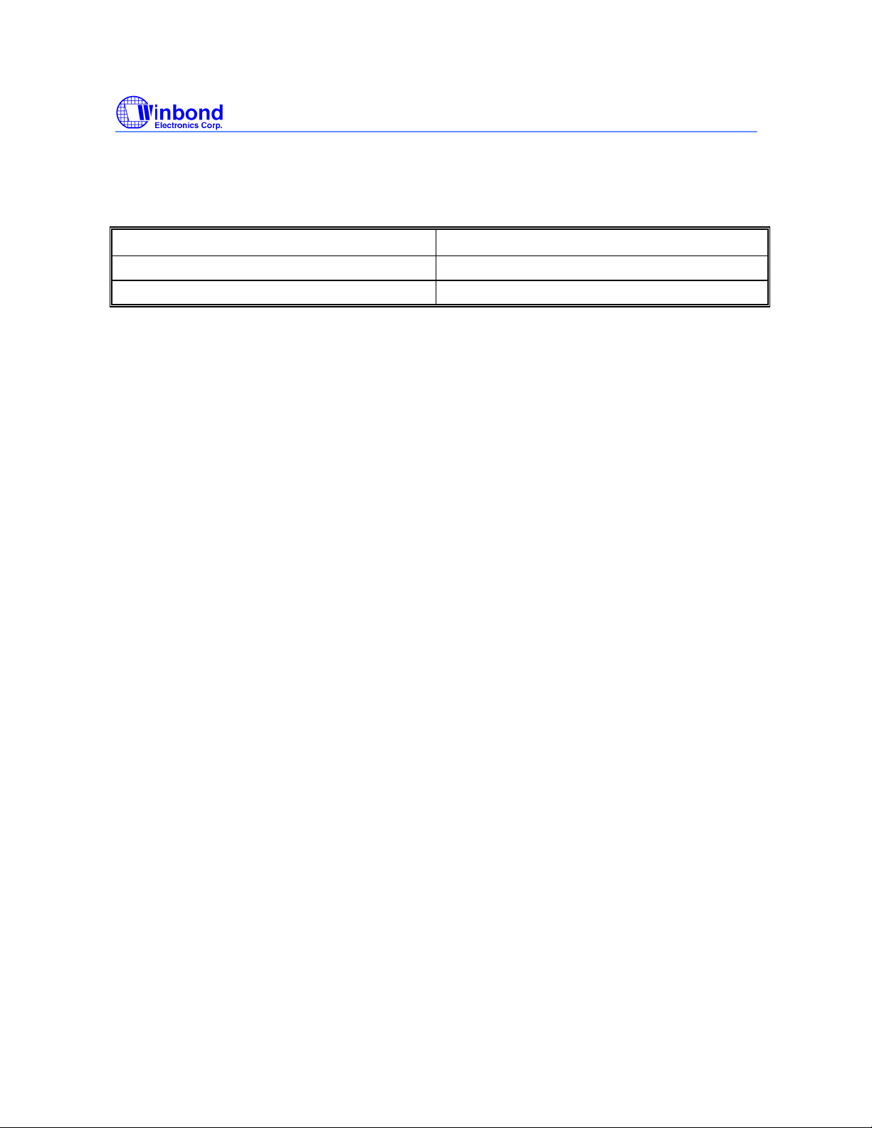
7.0 MODE PIN -POWER MANAGEMENT INPUT CONTROL
MODE, Pin7 (Latched Input) PIN 2
0 PCI_STOP# (Input)
1 REF0 (Output)
PRELIMINARY
Publication Release Date: May 1998
- 7 - Revision 0.20
Page 8
W83194R-39/-39A
PRELIMINARY
8.0 FUNTION DESCRIPTION
8.1 POWER MANAGEMENT FUNCTIONS
All clocks can be individually enabled or disabled via the 2-wire control interface. On power up,
external circuitry should allow 3 ms for the VCO’s to stabilize prior to enabling clock outputs to
assure correct pulse widths. When MODE=0, pins 15 and 46 are inputs (PCI_STOP#),
(CPU_STOP#), when MODE=1, these functions are not available. A particular clock could be
enabled as both the 2-wire serial control interface and one of these pins indicate that it should be
enable.
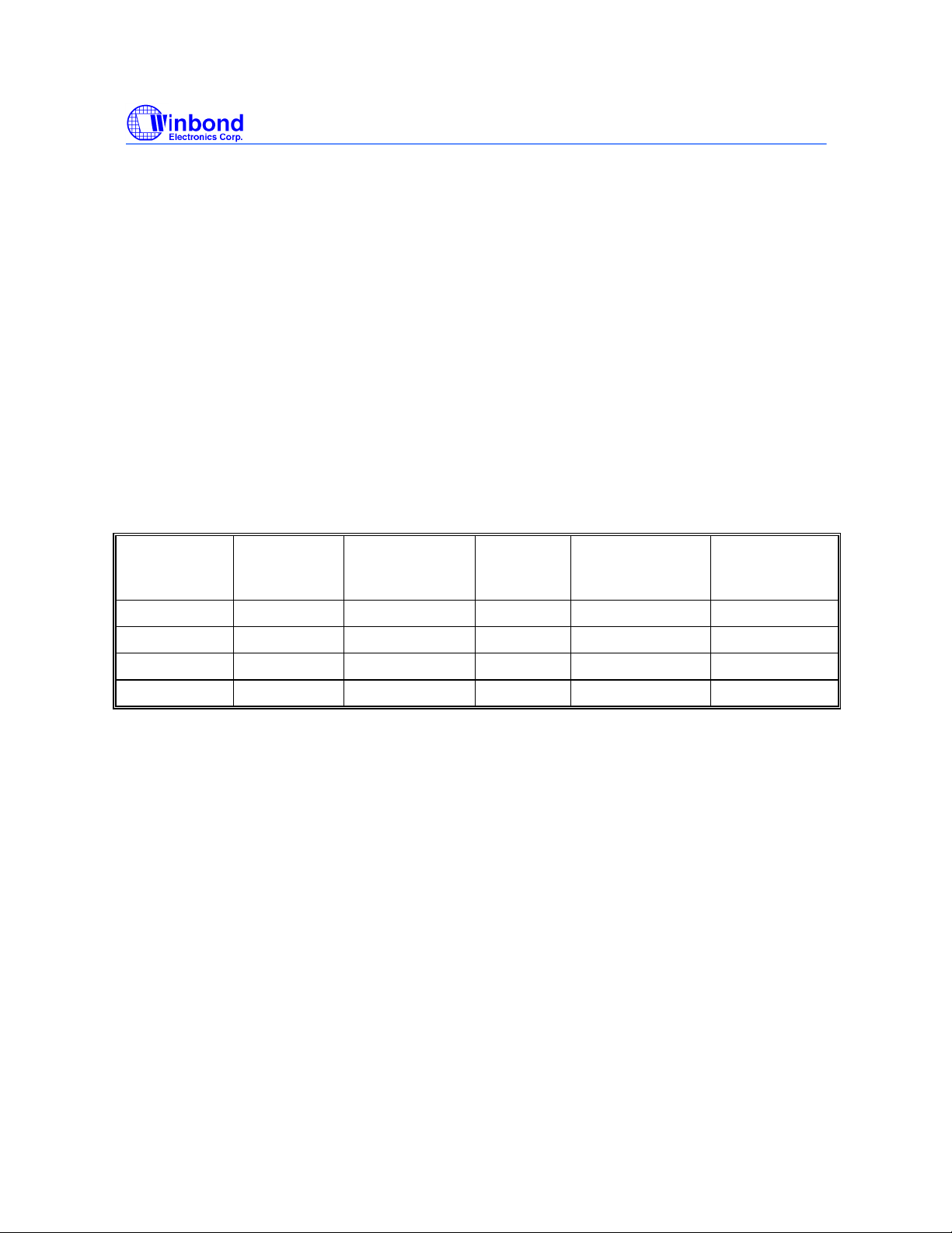
The W83194R-39/-39Amay be disabled in the low state according to the following table in order to
reduce power consumption. All clocks are stopped in the low state, but maintain a valid high period
on transitions from running to stop. The CPU and PCI clocks transform between running and stop by
waiting for one positive edge on PCICLK_F followed by negative edge on the clock of interest, after
which high levels of the output are either enabled or disabled.
CPU_STOP# PCI_STOP# CPUCLK1,
IOAPIC &
SDRAM 0:12
0 0 LOW LOW RUNNING RUNNING
0 1 LOW RUNNING RUNNING RUNNING
1 0 RUNNING LOW RUNNING RUNNING
1 1 RUNNING RUNNING RUNNING RUNNING
PCI OTHER CLKs XTAL & VCOs
8.2 2-WIRE I2C CONTROL INTERFACE
The clock generator is a slave I2C component which can be “read back” the data stored in the
latches for verification. All proceeding bytes must be sent to change one of the control bytes. The 2wire control interface allows each clock output individually enabled or disabled. On power up, the
W83194R-39/-39Ainitializes with default register settings, and then it’s optional to use the 2-wire
control interface.
The SDATA signal only changes when the SDCLK signal is low, and is stable when SDCLK is high
during normal data transfer. There are only two exceptions. One is a high-to-low transition on
SDATA while SDCLK is high used to indicate the beginning of a data transfer cycle. The other is a
low-to-high transition on SDATA while SDCLK is high used to indicate the end of a data transfer
cycle. Data is always sent as complete 8-bit bytes followed by an acknowledge generated.
Byte writing starts with a “start” condition followed by 7-bit slave address and a write command bit
[1101 0010], command code checking [0000 0000], and byte count checking. After successful
reception of each byte, an “acknowledge“ (low) on the SDATA wire will be generated by the clock
chip. Controller can start to write to internal I2C registers after the string of data. The sequence
order is as follows:
Publication Release Date: May 1998
- 8 - Revision 0.20
Page 9
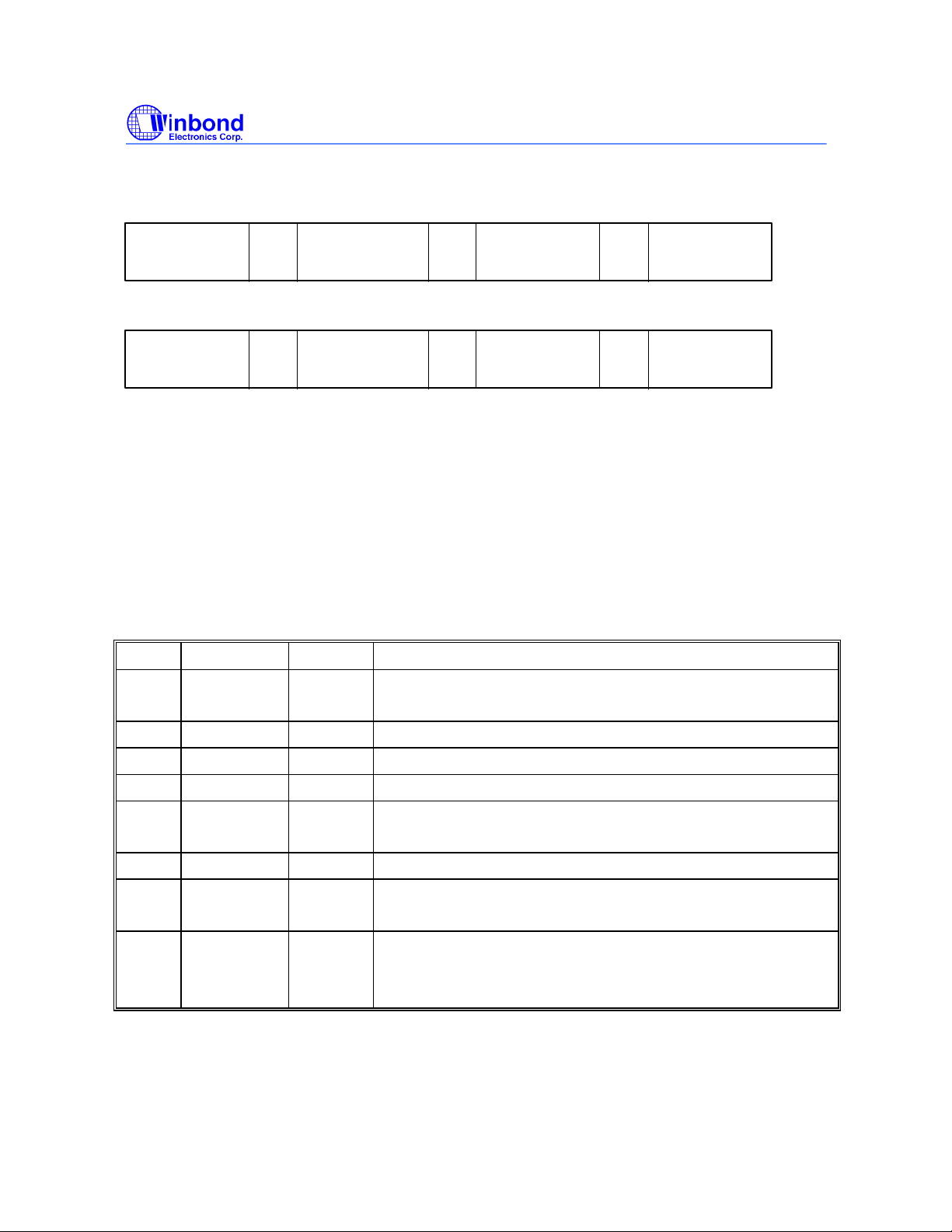
Bytes sequence order for I2C controller :
W83194R-39/-39A
PRELIMINARY
Clock Address
A(6:0) & R/W
Ack
8 bits dummy
Command code
Ack
8 bits dummy
Byte count
Ack
Byte0,1,2...
until Stop
Set R/W to 1 when “read back”, the data sequence is as follows :
Clock Address
A(6:0) & R/W
Ack
Byte 0 Ack
Byte 1
Ack
Byte2, 3, 4...
until Stop
8.3 SERIAL CONTROL REGISTERS
The Pin column lists the affected pin number and the @PowerUp column gives the default state at
true power up. "Command Code" byte and "Byte Count" byte must be sent following the
acknowledge of the Address Byte. Although the data (bits) in these two bytes are considered "don't
care", they must be sent and will be acknowledge. After that, the below described sequence
(Register 0, Register 1, Register 2, ....) will be valid and acknowledged.
8.3.1 Register 0: CPU Frequency Select Register (default = 0)
Bit @PowerUp Pin Description
7 0 - 0 = ¡Ó0.25% Spread Spectrum Modulation
1 = ¡Ó0.5% Spread Spectrum Modulation
6 0 - SSEL2 (for frequency table selection by software via I2C)
5 0 - SSEL1 (for frequency table selection by software via I2C)
4 0 - SSEL0 (for frequency table selection by software via I2C)
3 0 - 0 = Selection by hardware
1 = Selection by software I2C - Bit 6:4
2 0 - SSEL3 (for frequency table selection by software via I2C)
1 0 - 0 = Normal
1 = Spread Spectrum enabled
0 0 - 0 = Running
1 = Tristate all outputs
Note : The frequency table selected by software via I2C is the same as the hardware setting
frequency table.
Publication Release Date: May 1998
- 9 - Revision 0.20
Page 10
W83194R-39/-39A
PRELIMINARY
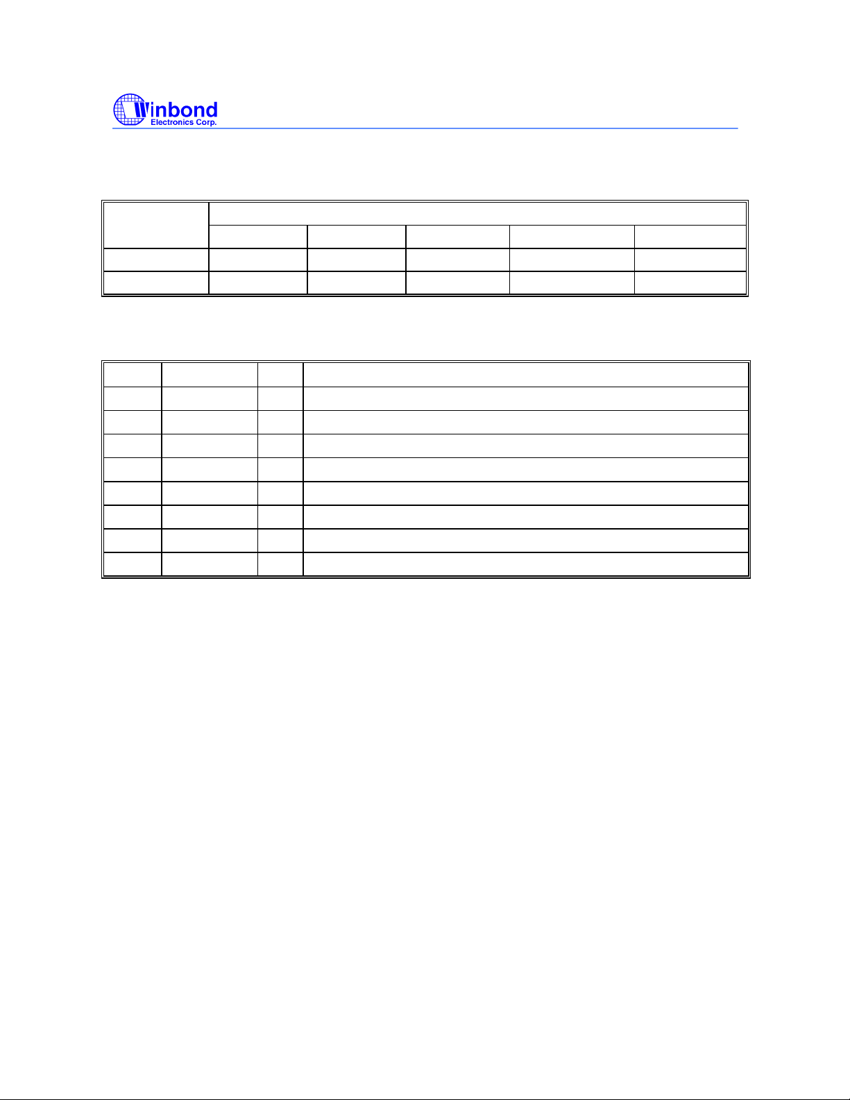
Function Table
Function Outputs
Description CPU PCI SDRAM REF IOAPIC
Tri-State Hi-Z Hi-Z Hi-Z Hi-Z Hi-Z
Normal see table see table CPU 14.318 14.318
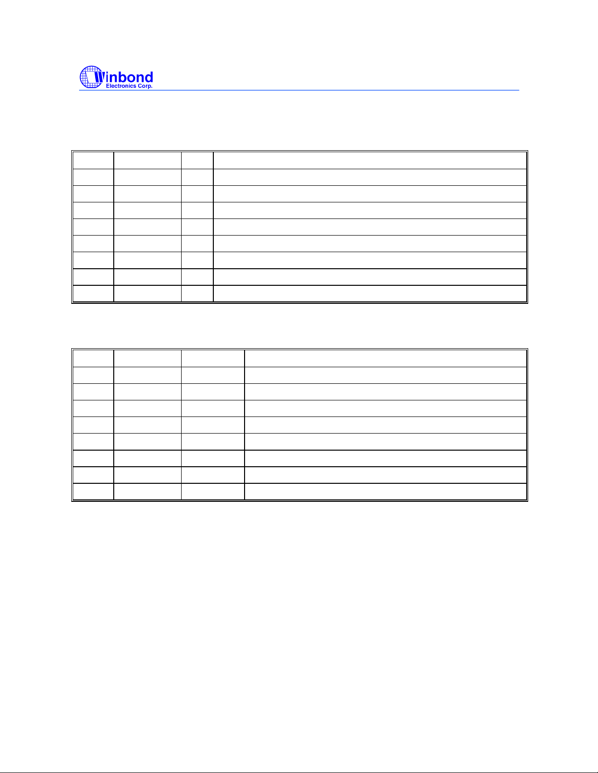
8.3.2 Register 1 : CPU , 48/24 MHz Clock Register (1 = enable, 0 = Stopped)
Bit @PowerUp Pin Description
7 1 - Latched FS2#
6 1 - Reserved
5 1 - Reserved
4 1 - Reserved
3 1 40 SDRAM12 (Active / Inactive)
2 1 - Reserved
1 1 43 CPUCLK1 (Active / Inactive)
0 1 44 CPUCLK_F (Active / Inactive)
Publication Release Date: May 1998
- 10 - Revision 0.20
Page 11
W83194R-39/-39A
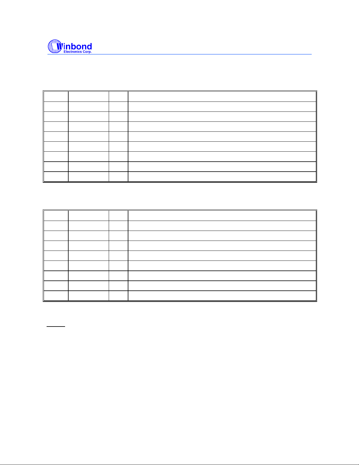
8.3.3 Register 2: PCI Clock Register (1 = enable, 0 = Stopped)
Bit @PowerUp Pin Description
7 1 - Reserved
6 1 7 PCICLK_F (Active / Inactive)
5 1 - Reserved
4 1 14 PCICLK4 (Active / Inactive)
3 1 12 PCICLK3 (Active / Inactive)
2 1 11 PCICLK2 (Active / Inactive)
1 1 10 PCICLk1 (Active / Inactive)
0 1 8 PCICLK0 (Active / Inactive)
8.3.4 Register 3: SDRAM Clock Register ( 1 = enable, 0 = Stopped )
PRELIMINARY
Bit @PowerUp Pin Description
7 1 - Reserved
6 1 - Reserved
5 1 26 48MHz (Active / Inactive)
4 1 25 24MHz (Active / Inactive)
3 1 - Reserved
2 1 21,20,18,17 SDRAM(8:11) (Active / Inactive)
1 1 32,31,29,28 SDRAM(4:7) (Active / Inactive)
0 1 38,37,35,34 SDRAM(0:3) (Active / Inactive)
Publication Release Date: May 1998
- 11 - Revision 0.20
Page 12
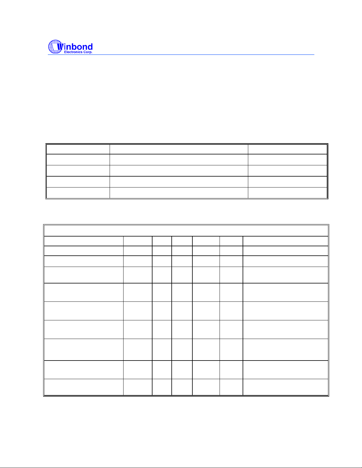
8.3.5 Register 4: Reserved Register (1 = enable, 0 = Stopped)
Bit @PowerUp Pin Description
7 1 - Reserved
6 1 - Reserved
5 1 - Reserved
4 1 - Reserved
3 1 - Latched FS1#
2 1 - Reserved
1 1 - Reserved
0 1 - Reserved
8.3.6 Register 5: Peripheral Control (1 = enable, 0 = Stopped)
W83194R-39/-39A
PRELIMINARY
Bit @PowerUp Pin Description
7 1 - Reserved
6 1 - Reserved
5 1 - Reserved
4 1 47 IOAPIC (Active / Inactive)
3 1 - Reserved
2 1 - Reserved
1 1 46 REF1 (Active / Inactive)
0 1 2 REF0 (Active / Inactive)
NOTE:
1. Inactive means outputs are held LOW and are disabled from switching.
2. Latched Frequency Selects(FS#) will be inverted logic load of the input frequency select pin
conditions.
Publication Release Date: May 1998
- 12 - Revision 0.20
Page 13
W83194R-39/-39A
PRELIMINARY
9.0 SPECIFICATIONS
9.1 ABSOLUTE MAXIMUM RATINGS
Stresses greater than those listed in this table may cause permanent damage to the device.
Precautions should be taken to avoid application of any voltage higher than the maximum rated
voltages to this circuit. Maximum conditions for extended periods may affect reliability. Unused
inputs must always be tied to an appropriate logic voltage level (Ground or Vdd).
Symbol Parameter Rating
Vdd , V
T
STG
T
B
T
A
IN
Voltage on any pin with respect to GND - 0.5 V to + 7.0 V
Storage Temperature
Ambient Temperature
Operating Temperature
- 65°C to + 150°C
- 55°C to + 125°C
0°C to + 70°C
9.2 AC CHARACTERISTICS
Vdd = Vddq3 = 3.3V ± 5 %, Vddq2 = VddL1=VddL2 = 2.375V~2.9V , TA = 0°C to +70°C
Parameter Symbol Min Typ Max Units Test Conditions
Output Duty Cycle 45 50 55 % Measured at 1.5V
CPU/SDRAM to PCI Offset
Skew (CPU-CPU), (PCIPCI), (SDRAM-SDRAM)
CPU/SDRAM
t
OFF
t
SKEW
t
CCJ
Cycle to Cycle Jitter
CPU/SDRAM
t
JA
Absolute Jitter
Jitter Spectrum 20 dB
BWJ 500 KHz
Bandwidth from Center
Output Rise (0.4V ~ 2.0V)
& Fall (2.0V ~0.4V) Time
Overshoot/Undershoot
t
TLH
t
THL
Vover 0.7 1.5 V
Beyond Power Rails
Ring Back Exclusion VRBE 0.7 2.1 V Ring Back must not enter this
1 4 ns 15 pF Load Measured at 1.5V
250 ps 15 pF Load Measured at 1.5V
¡Ó
250 ps
500 ps
0.4 1.6 ns 15 pF Load on CPU and PCI
outputs
22 Ω at source of 8 inch PCB
run to 15 pF load
range.
Publication Release Date: May 1998
- 13 - Revision 0.20
Page 14
W83194R-39/-39A
PRELIMINARY
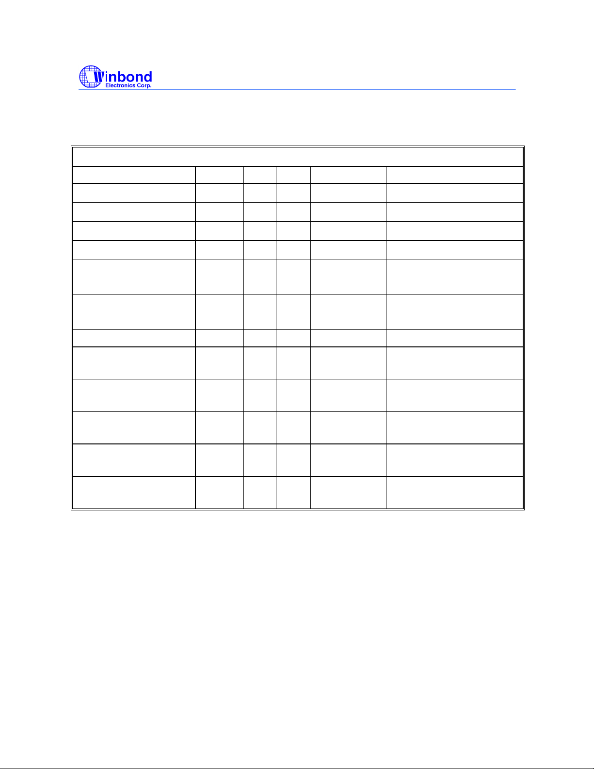
9.3 DC CHARACTERISTICS
Vdd = Vddq3 = 3.3V ± 5 %, Vddq2 = VddL1=VddL2 = 2.375V~2.9V , TA = 0°C to +70°C
Parameter Symbol Min Typ Max Units Test Conditions
Input Low Voltage
Input High Voltage
Input Low Current
Input High Current
Output Low Voltage
I
= 4 mA
OL
Output High Voltage
V
IL
V
IH
I
IL
I
IH
V
OL
V
OH
2.0
2.4
0.8
-66
5
0.4
IOH = 4mA
Tri-State leakage Current Ioz 10
Dynamic Supply Current
I
dd3
for Vdd + Vddq3
Dynamic Supply Current
I
dd2
for Vddq2 + Vddq2b
CPU Stop Current
I
CPUS3
for Vdd + Vddq3
CPU Stop Current
I
CPUS2
for Vddq2 + Vddq2b
V
dc
V
dc
µA
µA
V
V
All outputs
dc
All outputs using 3.3V power
dc
µA
mA CPU = 66.6 MHz
PCI = 33.3 Mhz with load
mA Same as above
mA Same as above
mA Same as above
PCI Stop Current
for Vdd + Vddq3
I
PD3
mA
Publication Release Date: May 1998
- 14 - Revision 0.20
Page 15
9.4 BUFFER CHARACTERISTICS
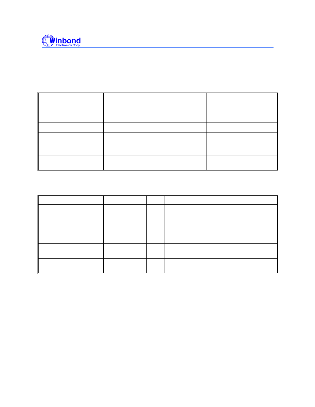
9.4.1 TYPE 1 BUFFER FOR CPU CLOCK
Parameter Symbol Min Typ Max Units Test Conditions
W83194R-39/-39A
PRELIMINARY
Pull-Up Current Min
Pull-Up Current Max
Pull-Down Current Min
Pull-Down Current Max I
Rise/Fall Time Min
Between 0.4 V and 2.0 V
Rise/Fall Time Max
Between 0.4 V and 2.0 V
I
OH(min)
I
OH(max)
I
OL(min)
OL(max)
T
RF(min)
T
RF(max)
-27 mA Vout = 1.0 V
0.4 ns 10pF Load
9.4.2 TYPE 2 BUFFER FOR IOAPIC
Parameter Symbol Min Typ Max Units Test Conditions
Pull-Up Current Min
Pull-Up Current Max
Pull-Down Current Min
Pull-Down Current Max I
Rise/Fall Time Min
Between 0.7 V and 1.7 V
I
OH(min)
I
OH(max)
I
OL(min)
OL(max)
T
RF(min)
0.4 ns 10pF Load
-27 mA Vout = 2.0V
mA Vout = 1.2 V
27 mA Vout = 0.3 V
1.6 ns 20pF Load
mA Vout = 1.4 V
-29 mA Vout = 2.7 V
mA Vout = 1.0 V
28 mA Vout = 0.2 V
Rise/Fall Time Max
Between 0.7 V and 1.7 V
T
RF(max)
1.8 ns 20pF Load
Publication Release Date: May 1998
- 15 - Revision 0.20
Page 16
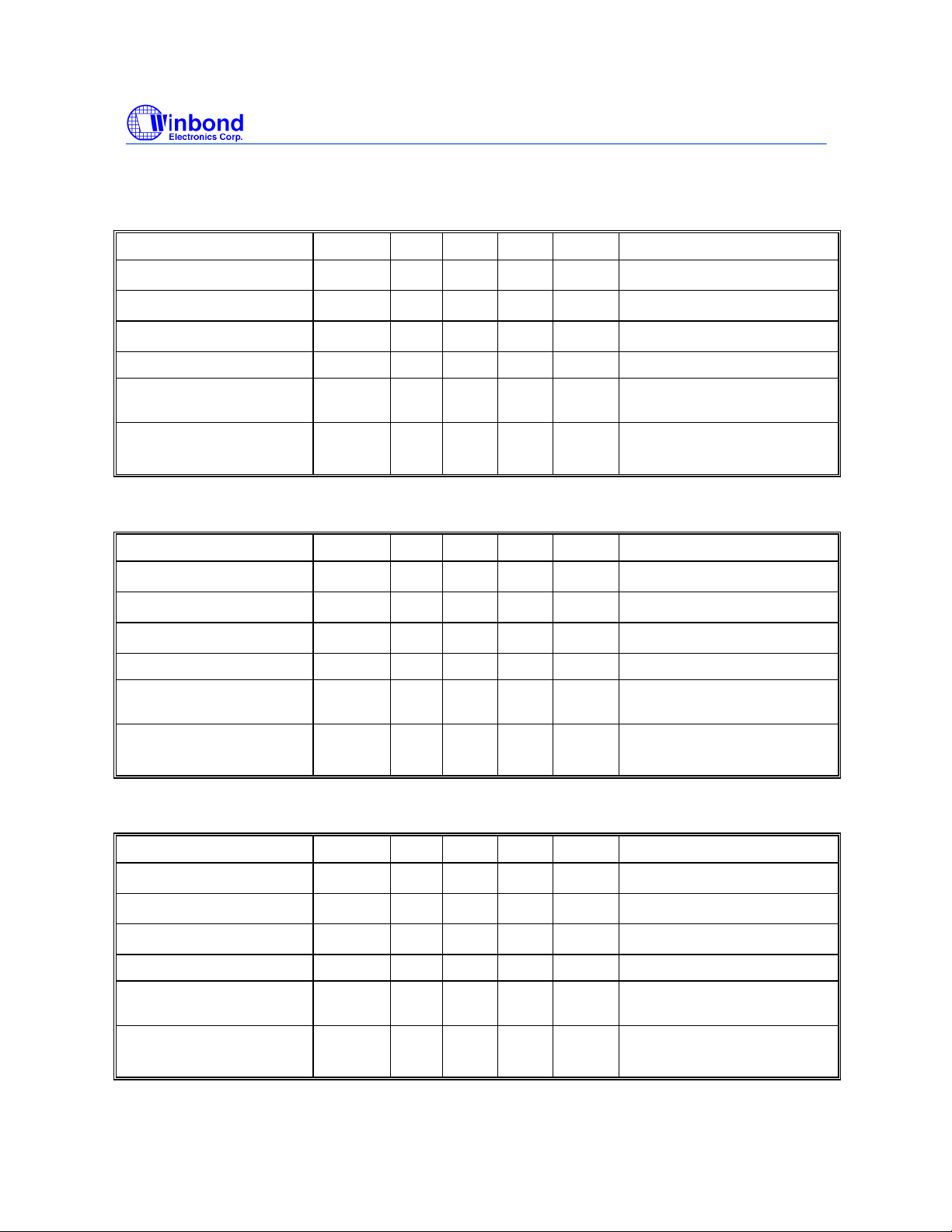
9.4.3 TYPE 3 BUFFER FOR REF1, 24MHZ, 48MHZ
Parameter Symbol Min Typ Max Units Test Conditions
W83194R-39/-39A
PRELIMINARY
Pull-Up Current Min
Pull-Up Current Max
Pull-Down Current Min
Pull-Down Current Max I
Rise/Fall Time Min
Between 0.8 V and 2.0 V
Rise/Fall Time Max
I
OH(min)
I
OH(max)
I
OL(min)
OL(max)
T
RF(min)
T
RF(max)
-29 mA Vout = 1.0 V
29 mA Vout = 1.95 V
1.0 ns 10pF Load
Between 0.8 V and 2.0 V
9.4.4 TYPE 4 BUFFER FOR SDRAM (0:12)
Parameter Symbol Min Typ Max Units Test Conditions
Pull-Up Current Min
Pull-Up Current Max
Pull-Down Current Min
Pull-Down Current Max I
Rise/Fall Time Min
Between 0.8 V and 2.0 V
I
OH(min)
I
OH(max)
I
OL(min)
OL(max)
T
RF(min)
0.5 ns 20pF Load
-23 mA Vout = 3.135V
mA Vout = 0.4 V
4.0 ns 20pF Load
mA Vout = 1.65 V
-46 mA Vout = 3.135 V
mA Vout = 1.65 V
53 mA Vout = 0.4 V
Rise/Fall Time Max
T
RF(max)
Between 0.8 V and 2.0 V
9.4.5 TYPE 5 BUFFER FOR PCICLK(0:4,F)
Parameter Symbol Min Typ Max Units Test Conditions
Pull-Up Current Min
Pull-Up Current Max
Pull-Down Current Min
Pull-Down Current Max I
Rise/Fall Time Min
Between 0.8 V and 2.0 V
Rise/Fall Time Max
Between 0.8 V and 2.0 V
I
OH(min)
I
OH(max)
I
OL(min)
OL(max)
T
RF(min)
T
RF(max)
-33 mA Vout = 1.0 V
30 mA Vout = 1.95 V
0.5 ns 15pF Load
- 16 - Revision 0.20
1.3 ns 30pF Load
-33 mA Vout = 3.135 V
38 mA Vout = 0.4 V
2.0 ns 30pF Load
Publication Release Date: May 1998
Page 17
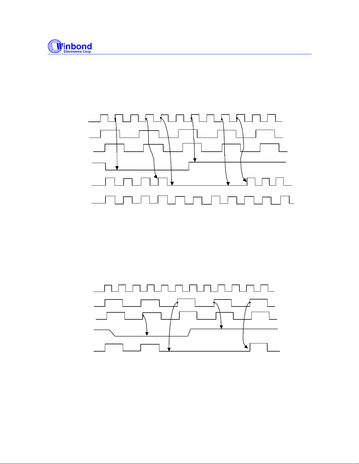
10.0 POWER MANAGEMENT TIMING
10.1 CPU_STOP# Timing Diagram
W83194R-39/-39A
PRELIMINARY
CPUCLK
(Internal)
PCICLK
(Internal)
PCICLK_F
CPU_STOP#
CPUCLK[0:3]
SDRAM
1 2 3 4 1 2
4
3
For synchronous Chipset, CPU_STOP# pin is an asynchronous “ active low ” input pin used to stop
the CPU clocks for low power operation. This pin is asserted synchronously by the external control
logic at the rising edge of free running PCI clock(PCICLK_F). All other clocks will continue to run
while the CPU clocks are stopped. The CPU clocks will always be stopped in a low state and resume
output with full pulse width. In this case, CPU “clocks on latency“ is less than 4 CPU clocks and
“c
locks off latency” is less then 4 CPU clocks.
10.2 PCI_STOP# Timing Diagram
CPUCLK
(Internal)
PCICLK
(Internal)
PCICLK_F
PCI_STOP#
PCICLK[0:5]
1
2
1
2
For synchronous Chipset, PCI_STOP# pin is an asynchronous “active low” input pin used to stop
the PCICLK [0:4] for low power operation. This pin is asserted synchronously by the external control
logic at the rising edge of free running PCI clock(PCICLK_F). All other clocks will continue to run
while the PCI clocks are stopped. The PCI clocks will always be stopped in a low state and resume
output with full pulse width. In this case, PCI “clocks on latency“ is less than 2 PCI clocks and
“c
locks off latency” is less then 2 PCI clocks.
Publication Release Date: May 1998
- 17 - Revision 0.20
Page 18
W83194R-39/-39A
PRELIMINARY
11.0 OPERATION OF DUAL FUCTION PINS
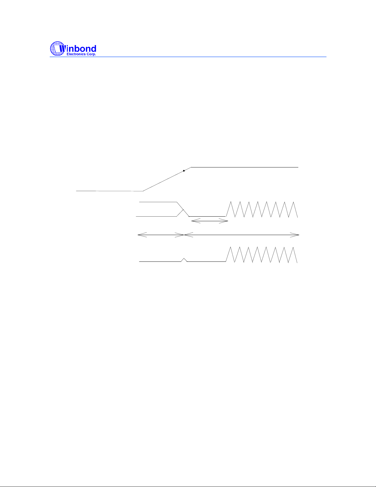
Pins 2, 7, 8, 25, and 26 are dual function pins and are used for selecting different functions in this
device (see Pin description). During power up, these pins are in input mode (see Fig1), therefore,
and are considered input select pins. When Vdd reaches 2.5V, the logic level that is present on these
pins are latched into their appropriate internal registers. Once the correct information are properly
latched, these pins will change into output pins and will be pulled low by default. At the end of the
power up timer (within 3 ms) outputs starts to toggle at the specified frequency.
2.5V
Vdd
#7 PCICLK_F/MODE
#46 REF1/FS2
#25 24/FS1
#26 48/FS0
All other clocks
Output tri-state
Input
Output tri-state
Output pull-low
Within 3ms
Output
Output pull-low
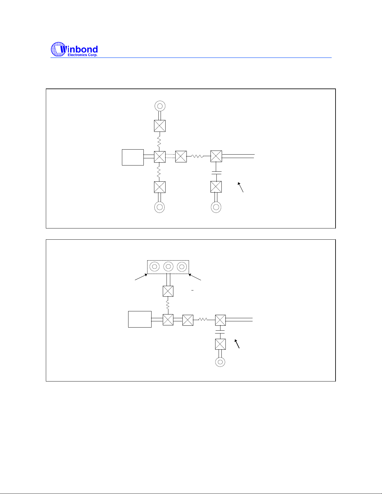
Each of these pins are a large pull-up resistor ( 250 kΩ @3.3V ) inside. The default state will be logic
1, but the internal pull-up resistor may be too large when long traces or heavy load appear on these
dual function pins. Under these conditions, an external 10 kΩ resistor is recommended to be
connected to Vdd if logic 1 is expected. Otherwise, the direct connection to ground if a logic 0 is
desired. The 10 kΩ resistor should be place before the serious terminating resistor. Note that these
logic will only be latched at initial power on.
If optional EMI reducing capacitor are needed, they should be placed as close to the series
terminating resistor as possible and after the series terminating resistor. These capacitor has typical
values ranging from 4.7pF to 22pF.
Publication Release Date: May 1998
- 18 - Revision 0.20
Page 19
Vdd
W83194R-39/-39A
PRELIMINARY
Device
Pin
Programming Header
Vdd Pad
10k
Device
Pin
10k
10kΩΩ
Ground Ground
Ω
Series
Terminating
Resistor
Ground Pad
Series
Terminating
Resistor
Clock
Trace
EMI
Reducing
Cap
Optional
Clock
Trace
EMI
Reducing
Cap
Optional
Ground
Publication Release Date: May 1998
- 19 - Revision 0.20
Page 20
13.0 ORDERING INFORMATION
Part Number Package Type Production Flow
W83194R-39/-39A
PRELIMINARY
W83194R-39/-39A 48 PIN SSOP
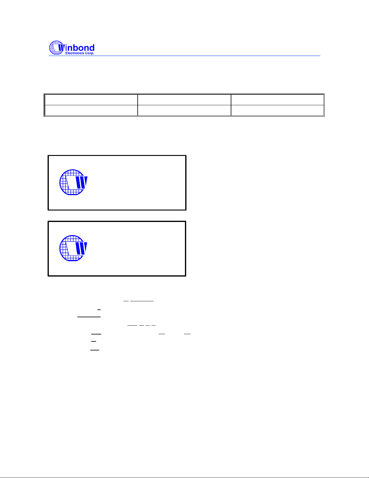
14.0 HOW TO READ THE TOP MARKING
W83194R-39
28051234
814GBB
W83194R-39A
28051234
814GBB
Commercial, 0°C to +70°C
1st line: Winbond logo and the type number: W83194R-39/-39A
2nd line: Tracking code 2 8051234
2: wafers manufactured in Winbond FAB 2
8051234: wafer production series lot number
3rd line: Tracking code 814 G B B
814: packages made in '98, week 14
G: assembly house ID; A means ASE, S means SPIL, G means GR
BB: IC revision
All the trade marks of products and companies mentioned in this data sheet belong to
their respective owners.
Publication Release Date: May 1998
- 20 - Revision 0.20
Page 21
15.0 PACKAGE DRAWING AND DIMENSIONS
W83194R-39/-39A
PRELIMINARY
Headquarters
No. 4, Creation Rd. III
Science-Based Industrial Park
Hsinchu, Taiwan
TEL: 886-35-770066
FAX: 886-35-789467
www: http://www.winbond.com.tw/
Taipei Office
11F, No. 115, Sec. 3, Min-Sheng East Rd.
Taipei, Taiwan
TEL: 886-2-7190505
FAX: 886-2-7197502
TLX: 16485 WINTPE
Winbond Electronics (H.K.) Ltd.
Rm. 803, World Trade Square, Tower II
123 Hoi Bun Rd., Kwun Tong
Kowloon, Hong Kong
TEL: 852-27516023-7
FAX: 852-27552064
Winbond Electronics
(North America) Corp.
2730 Orchard Parkway
San Jose, CA 95134 U.S.A.
TEL: 1-408-9436666
FAX: 1-408-9436668
Please note that all data and specifications are subject to change without notice. All the
trade marks of products and companies mentioned in this data sheet belong to their
respective owners.
These products are not designed for use in life support appliances, devices, or systems
where malfunction of these products can reasonably be expected to result in personal
injury. Winbond customers using or selling these products for use in such applications
do so at their own risk and agree to fully indemnify Winbond for any damages resulting
from such improper use or sale.
Publication Release Date: May 1998
- 21 - Revision 0.20
 Loading...