

Page 1

www.DataSheet4U.com
查询W78E058B供应商查询W78E058B供应商
W78E58B/W78E058B Data Sheet
8-BIT MICROCONTROLLER
Table of Contents-
1. GENERAL DESCRIPTION ............................................................................................................... 3
2. FEATURES....................................................................................................................................... 3
3. PIN CONFIGURATIONS .................................................................................................................. 4
4. PIN DESCRIPTION .......................................................................................................................... 5
5. FUNCTIONAL DESCRIPTION ......................................................................................................... 6
5.1 RAM ....................................................................................................................................... 6
5.2 Timers 0, 1 and 2................................................................................................................... 6
5.3 Clock ...................................................................................................................................... 7
5.4 Crystal Oscillator.................................................................................................................... 7
5.5 External Clock........................................................................................................................ 7
5.6 Power Management............................................................................................................... 7
5.7 Reduce EMI Emission ........................................................................................................... 7
5.8 Reset...................................................................................................................................... 7
5.9 Port 4 ..................................................................................................................................... 9
5.10 INT2 / NT3I ............................................................................................................................ 9
5.11 Port 4 Base Address Registers ........................................................................................... 11
5.12 In-System Programming (ISP) Mode................................................................................... 13
5.13 In-System Programming Control Register (CHPCON) ....................................................... 15
5.14 F04KBOOT Mode (Boot From LDROM) ............................................................................. 15
6. SECURITY...................................................................................................................................... 19
6.1 Lock Bit ................................................................................................................................ 19
6.2 MOVC Inhibit ....................................................................................................................... 19
6.3 Encryption............................................................................................................................ 20
6.4 Oscillator Control ................................................................................................................. 20
7. ELECTRICAL CHARACTERISTICS............................................................................................... 21
7.1 Absolute Maximum Ratings................................................................................................. 21
7.2 D.C. Characteristics............................................................................................................. 21
7.3 A.C. Characteristics ............................................................................................................. 23
7.3.1 Clock Input Waveform...........................................................................................................23
7.3.2 Program Fetch Cycle ............................................................................................................23
7.3.3 Data Read Cycle...................................................................................................................24
7.3.4 Data Write Cycle...................................................................................................................24
7.3.5 Port Access Cycle.................................................................................................................24
Publication Release Date: December 4, 2006
- 1 - Revision A8
Page 2

W78E58B/W78E058B
TIMING WAVEFORMS................................................................................................................... 25
8.
8.1 Program Fetch Cycle ........................................................................................................... 25
8.2 Data Read Cycle.................................................................................................................. 25
8.3 Data Write Cycle.................................................................................................................. 26
8.4 Port Access Cycle................................................................................................................ 26
9. TYPICAL APPLICATION CIRCUITS .............................................................................................. 27
9.1 Expanded External Program Memory and Crystal .............................................................. 27
9.2 Expanded External Data Memory and Oscillator ................................................................ 28
10. PACKAGE DIMENSIONS............................................................................................................... 29
10.1 40-pin DIP............................................................................................................................ 29
10.2 44-pin PLCC ........................................................................................................................ 29
10.3 44-pin PQFP ........................................................................................................................ 30
11. APPLICATION NOTES................................................................................................................... 31
11.1 In-system Programming Software Examples ...................................................................... 31
12. REVISION HISTORY...................................................................................................................... 36
- 2 -
Page 3

W78E58B/W78E058B
1. GENERAL DESCRIPTION
The W78E058B is an 8-bit microcontroller which has an in-system programmable Flash EPROM for
firmware updating. The instruction set of the W78E058B is fully compatible with the standard 8052.
The W78E058B contains a 32K bytes of main ROM and a 4K bytes of auxiliary ROM which allows the
contents of the 32KB main ROM to be updated by the loader program located at the 4KB auxiliary
ROM; 512 bytes of on-chip RAM; four 8-bit bi-directional and bit-addressable I/O ports; an additional
4-bit port P4; three 16-bit timer/counters; a serial port. These peripherals are supported by a eight
sources two-level interrupt capability. To facilitate programming and verification, the ROM inside the
W78E058B allows the program memory to be programmed and read electronically. Once the code is
confirmed, the user can protect the code for security.
The W78E058B microcontroller has two power reduction modes, idle mode and power-down mode,
both of which are software selectable. The idle mode turns off the processor clock but allows for
continued peripheral operation. The power-down mode stops the crystal oscillator for minimum power
consumption. The external clock can be stopped at any time and in any state without affecting the
processor.
2. FEATURES
y Fully static design 8-bit CMOS microcontroller
y 32K bytes of in-system programmable Flash EPROM for Application Program (APROM)
y 4K bytes of auxiliary ROM for Loader Program (LDROM)
y 512 bytes of on-chip RAM (including 256 bytes of AUX-RAM, software selectable)
y 64K bytes program memory address space and 64K bytes data memory address space
y Four 8-bit bi-directional ports
y One 4-bit multipurpose programmable port
y Three 16-bit timer/counters
y One full duplex serial port
y Eight-sources, two-level interrupt capability
y Built-in power management
y Code protection
y Packaged in
− Lead Free (RoHS) DIP 40: W78E058B40DL
− Lead Free (RoHS) PLCC 44: W78E058B40PL
− Lead Free (RoHS) PQFP 44: W78E058B40FL
Publication Release Date: December 4, 2006
- 3 - Revision A8
Page 4

3. PIN CONFIGURATIONS
40-Pin DIP
T2, P1.0
T2EX, P1.1
P1.2
P1.3
P1.4
P1.5
P1.6
P1.7
RST
RXD, P3.0
TXD, P3.1
INT0, P3.2
INT1, P3.3
T0, P3.4
T1, P3.5
WR, P3.6
RD, P3.7
XTAL2
XTAL1
VSS
W78E58B/W78E058B
VDD1
2
3
4
5
6
7
8
9
10
11
12
13
14
15
16
17
18
19
20
40
39
P0.0, AD0
38
P0.1, AD1
P0.2, AD2
37
P0.3, AD3
36
35
P0.4, AD4
34
P0.5, AD5
33
P0.6, AD6
32
P0.7, AD7
31
EA
ALE
30
29
PSEN
P2.7, A15
28
P2.6, A14
27
P2.5, A13
26
P2.4, A12
25
P2.3, A11
24
P2.2, A10
23
P2.1, A9
22
P2.0, A8
21
P1.5
P1.6
P1.7
RST
RXD, P3.0
INT2, P4.3
TXD, P3.1
INT0, P3.2
INT1, P3.3
T0, P3.4
T1, P3.5
44-Pin PLCC
P
P
P
1
1
1
.
.
.
3
4
2
6543
7
8
9
10
11
12
13
14
15
16
17
X
P
P
T
3
3
A
.
.
L
7
6
,
,
2
/
/
R
W
D
R
/
T
I
2
N
E
T
T
X
2
3
,
,
,
P
P
P
1
1
4
.
.
.
1
0
2
2 1 44 43 42
V
X
P
S
T
4
A
S
.
L
0
1
44-Pin QFP
/
T
I
2
N
T
E
A
A
A
A
D
D
D
D
3
1
2
0
,
,
,
,
P
P
P
P
0
0
V
0
0
.
.
.
D
.
3
1
D
2
0
40
41
39
P0.4, AD4
38
P0.5, AD5
37
P0.6, AD6
36
P0.7, AD7
35
EA
34
P4.1
33
ALE
32
PSEN
31
P2.7, A15
30
P2.6, A14
29
P2.5, A13
2827262524232221201918
P
P
P
P
P
2
2
2
2
2
.
.
.
.
.
3
4
1
0
2
,
,
,
,
,
A
A
A
A
A
8
1
1
9
1
1
2
0
P1.5
P1.6
P1.7
RST
RXD, P3.0
INT2, P4.3
TXD, P3.1
INT0, P3.2
INT1, P3.3
T0, P3.4
T1, P3.5
P
P
1
1
.
.
3
4
43 42 41
44
1
2
3
4
5
6
7
8
9
10
11
12
P
P
3
3
.
.
7
6
,
,
/
/
R
W
D
R
2
X
,
,
P
P
P
1
1
1
.
.
.
0
1
2
40 39 38 37 36 35
X
V
X
S
T
T
S
A
A
L
L
1
2
T
3
,
P
V
4
D
.
D
2
P
P
2
4
.
.
0
0
,
A
8
A
A
A
A
D
D
D
D
3
2
1
0
,
,
,
,
P
P
P
P
0
0
0
0
.
.
.
.
3
2
1
0
34
33
P0.4, AD4
32
P0.5, AD5
31
P0.6, AD6
30
P0.7, AD7
29
EA
28
P4.1
27
ALE
26
PSEN
25
P2.7, A15
24
P2.6, A14
23
P2.5, A13
22212019181716151413
P
P
P
P
2
2
2
2
.
.
.
.
4
3
1
2
,
,
,
,
A
A
A
A
1
1
9
1
1
2
0
- 4 -
Page 5

W78E58B/W78E058B
A
f
A
A
4. PIN DESCRIPTION
SYMBOL TYPE DESCRIPTIONS
EXTERNAL ACCESS ENABLE: This pin forces the processor to execute the
external ROM. The ROM address and data will not be presented on the bus i
E
I
E
the
pin is high.
PROGRAM STORE ENABLE:
PSEN
ALE O H
RST I L
XTAL1 I
XTAL2 O CRYSTAL 2: This is the crystal oscillator output. It is the inversion of XTAL1.
VSS I GROUND: Ground potential.
VDD I POWER SUPPLY: Supply voltage for operation.
P0.0 − P0.7
P1.0 − P1.7
P2.0 − P2.7
P3.0 − P3.7
P4.0 − P4.3
* Note: TYPE I: input, O: output, I/O: bi-directional, H: pull-high, L: pull-low, D: open drain
O H
I/O D PORT 0: Function is the same as that of standard 8052.
I/O H PORT 1: Function is the same as that of standard 8052.
I/O H
I/O H PORT 3: Function is the same as that of the standard 8052.
I/O H PORT 4: A bi-directional I/O. See details below.
Port 0 address/data bus. When internal ROM access is performed, no
strobe signal outputs originate from this pin.
ADDRESS L
separates the address from the data on Port 0. ALE runs at 1/6th of the
oscillator frequency.
RESET: A high on this pin for two machine cycles while the oscillator is
running resets the device.
CRYSTAL 1: This is the crystal oscillator input. This pin may be driven by an
external clock.
PORT 2: Port 2 is a bi-directional I/O port with internal pull-ups. This port also
provides the upper address bits for accesses to external memory.
TCH ENABLE: ALE is used to enable the address latch that
PSEN enables the external ROM data in the
PSEN
Publication Release Date: December 4, 2006
- 5 - Revision A8
Page 6

W78E58B/W78E058B
5. FUNCTIONAL DESCRIPTION
The W78E058B architecture consists of a core controller surrounded by various registers, four general
purpose I/O ports, one special purpose programmable 4-bits I/O port, 512 bytes of RAM, three
timer/counters, a serial port. The processor supports 111 different opcodes and references both a 64K
program address space and a 64K data storage space.
5.1 RAM
The internal data RAM in the W78E058B is 512 bytes. It is divided into two banks: 256 bytes of
scratchpad RAM and 256 bytes of AUX-RAM. These RAMs are addressed by different ways.
y RAM 0H − 7FH can be addressed directly and indirectly as the same as in 8051. Address pointers
are R0 and R1 of the selected register bank.
y RAM 80H − FFH can only be addressed indirectly as the same as in 8051. Address pointers are
R0, R1 of the selected registers bank.
y AUX-RAM 0H − FFH is addressed indirectly as the same way to access external data memory
with the MOVX instruction. Address pointer are R0 and R1 of the selected register bank and
DPTR register. An access to external data memory locations higher than FFH will be performed
with the MOVX instruction in the same way as in the 8051. The AUX-RAM is disable after a reset.
Setting the bit 4 in CHPCON register will enable the access to AUX-RAM. When AUX-RAM is
enabled the instructions of "MOVX @Ri" will always access to on-chip AUX-RAM. When executing
from internal program memory, an access to AUX-RAM will not affect the Ports P0, P2,
RD .
WR and
Example,
CHPENR REG F6H
CHPCON REG BFH
MOV CHPENR, #87H
MOV CHPENR, #59H
ORL CHPCON, #00010000B ; enable AUX-RAM
MOV CHPENR, #00H
MOV R0, #12H
MOV A, #34H
MOVX @R0, A ; Write 34h data to 12h address.
5.2 Timers 0, 1 and 2
Timers 0, 1, and 2 each consist of two 8-bit data registers. These are called TL0 and TH0 for Timer 0,
TL1 and TH1 for Timer 1, and TL2 and TH2 for Timer 2. The TCON and TMOD registers provide
control functions for timers 0, 1. The T2CON register provides control functions for Timer 2. RCAP2H
and RCAP2L are used as reload/capture registers for Timer 2. The operations of Timer 0 and Timer 1
are the same as in the W78C51. Timer 2 is a 16-bit timer/counter that is configured and controlled by
the T2CON register. Like Timers 0 and 1, Timer 2 can operate as either an external event counter or
as an internal timer, depending on the setting of bit C/T2 in T2CON. Timer 2 has three operating
modes: capture, auto-reload, and baud rate generator. The clock speed at capture or auto-reload
mode is the same as that of Timers 0 and 1.
- 6 -
Page 7

W78E58B/W78E058B
5.3 Clock
The W78E058B is designed with either a crystal oscillator or an external clock. Internally, the clock is
divided by two before it is used by default. This makes the W78E058B relatively insensitive to duty
cycle variations in the clock.
5.4 Crystal Oscillator
The W78E058B incorporates a built-in crystal oscillator. To make the oscillator work, a crystal must be
connected across pins XTAL1 and XTAL2. In addition, a load capacitor must be connected from each
pin to ground.
5.5 External Clock
An external clock should be connected to pin XTAL1. Pin XTAL2 should be left unconnected. The
XTAL1 input is a CMOS-type input, as required by the crystal oscillator.
5.6 Power Management
Idle Mode
Setting the IDL bit in the PCON register enters the idle mode. In the idle mode, the internal clock to
the processor is stopped. The peripherals and the interrupt logic continue to be clocked. The
processor will exit idle mode when either an interrupt or a reset occurs.
Power-down Mode
When the PD bit in the PCON register is set, the processor enters the power-down mode. In this
mode all of the clocks are stopped, including the oscillator. To exit from power-down mode is by a
hardware reset or external interrupts
INT0 to INT1 when enabled and set to level triggered.
5.7 Reduce EMI Emission
The W78E058B allows user to diminish the gain of on-chip oscillator amplifier by using programmer to
clear the B7 bit of security register. Once B7 is set to 0, a half of gain will be decreased. Care must be
taken if user attempts to diminish the gain of oscillator amplifier, reducing a half of gain may affect the
external crystal operating improperly at high frequency. The value of C1 and C2 may need some
adjustment while running at lower gain.
5.8 Reset
The external RESET signal is sampled at S5P2. To take effect, it must be held high for at least two
machine cycles while the oscillator is running. An internal trigger circuit in the reset line is used to
deglitch the reset line when the W78E058B is used with an external RC network. The reset logic also
has a special glitch removal circuit that ignores glitches on the reset line. During reset, the ports are
initialized to FFH, the stack pointer to 07H, PCON (with the exception of bit 4) to 00H, and all of the
other SFR registers except SBUF to 00H. SBUF is not reset.
Publication Release Date: December 4, 2006
- 7 - Revision A8
Page 8

W78E58B/W78E058B
W78E058B Special Function Registers (SFRs) and Reset Values
F8
F0
E8
E0
D8
D0
C8
C0
B8
B0
A8
A0
98
90
88
80
Notes:
1.The SFRs marked with a plus sign(+) are both byte- and bit-addressable.
2. The text of SFR with bold type characters are extension function registers.
+B
00000000
+ACC
00000000
+P4
xxxx1111
+PSW
00000000
+T2CON
00000000
XICON
00000000
+IP
00000000
+P3
00000000
+IE
00000000
+P2
11111111
+SCON
00000000
+P1
11111111
+TCON
00000000
+P0
11111111
RCAP2L
00000000
P4CONA
00000000
RCAP2H
00000000
P4CONB
00000000
TL2
00000000
SFRAL
00000000
00000000
SFRAH
00000000
A7
SBUF
xxxxxxxx
TMOD
00000000
SP
00000111
TL0
00000000
DPL
00000000
TL1
00000000
DPH
00000000
P43AL
00000000
P42AL
00000000
P41AL
00000000
TH0
00000000
P40AL
00000000
00000000
00000000
00000000
00000000
00000000
TH2
P43AH
P42AH
P41AH
TH1
P40AH
CHPENR
00000000
SFRFD
00000000
SFRCN
00000000
CHPCON
0xx00000
P2ECON
0000xx00
97
8F
AF
PCON
00110000
FF
F7
EF
E7
DF
D7
CF
C7
BF
B7
9F
87
- 8 -
Page 9

W78E58B/W78E058B
5.9 Port 4
Port 4, address D8H, is a 4-bit multipurpose programmable I/O port. Each bit can be configured
individually by software. The Port 4 has four different operation modes.
Mode 0: P4.0 − P4.3 is a bi-directional I/O port which is same as port 1. P4.2 and P4.3 also serve as
external interrupt
INT3 and NT2I if enabled.
Mode 1: P4.0 − P4.3 are read strobe signals that are synchronized with
addresses. These signals can be used as chip-select signals for external peripherals.
Mode 2: P4.0 − P4.3 are write strobe signals that are synchronized with
addresses. These signals can be used as chip-select signals for external peripherals.
Mode 3: P4.0 − P4.3 are read/write strobe signals that are synchronized with
specified addresses. These signals can be used as chip-select signals for external
peripherals.
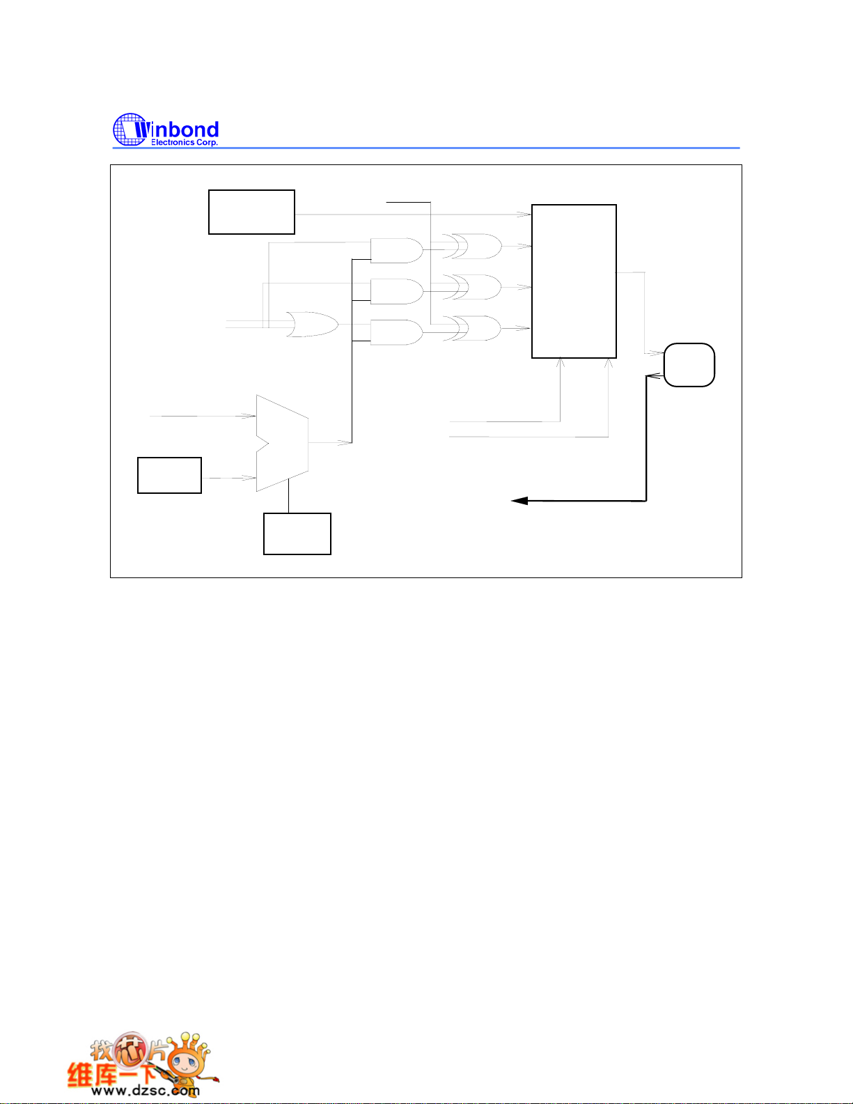
When Port 4 is configured with the feature of chip-select signals, the chip-select signal address range
depends on the contents of the SFR P4xAH, P4xAL, P4CONA and P4CONB. The registers P4xAH
and P4xAL contain the 16-bit base address of P4.x. The registers P4CONA and P4CONB contain the
control bits to configure the Port 4 operation mode.
RD signal at specified
WR signal at specified
RD or WR signal at
5.10 INT2 / NT3I
Two additional external interrupts,
interrupt 0 and 1 in the standard 80C52. The functions/status of these interrupts are
determined/shown by the bits in the XICON (External Interrupt Control) register. The XICON register is
bit-addressable but is not a standard register in the standard 80C52. Its address is at 0C0H. To
set/clear bits in the XICON register, one can use the "SETB (
"SETB 0C2H" sets the EX2 bit of XICON.
INT2
and INT3 , whose functions are similar to those of external
CLR ) bit" instruction. For example,
XICON - external interrupt control (C0H)
PX3 EX3 IE3 IT3 PX2 EX2 IE2 IT2
PX3: External interrupt 3 priority high if set
EX3: External interrupt 3 enable if set
IE3: If IT3 = 1, IE3 is set/cleared automatically by hardware when interrupt is detected/serviced
IT3: External interrupt 3 is falling-edge/low-level triggered when this bit is set/cleared by software
PX2: External interrupt 2 priority high if set
EX2: External interrupt 2 enable if set
IE2: If IT2 = 1, IE2 is set/cleared automatically by hardware when interrupt is detected/serviced
IT2: External interrupt 2 is falling-edge/low-level triggered when this bit is set/cleared by software
Publication Release Date: December 4, 2006
- 9 - Revision A8
Page 10

Eight-source interrupt information
A
W78E58B/W78E058B
INTERRUPT
SOURCE
External Interrupt 0 03H 0 (highest) IE.0 TCON.0
Timer/Counter 0 0BH 1 IE.1 -
External Interrupt 1 13H 2 IE.2 TCON.2
Timer/Counter 1 1BH 3 IE.3 -
Serial Port 23H 4 IE.4 -
Timer/Counter 2 2BH 5 IE.5 -
External Interrupt 2 33H 6 XICON.2 XICON.0
External Interrupt 3 3BH 7 (lowest) XICON.6 XICON.3
VECTOR
ADDRESS
POLLING
SEQUENCE WITHIN
PRIORITY LEVEL
ENABLE
REQUIRED
SETTINGS
INTERRUPT
TYPE
EDGE/LEVEL
P4CONB (C3H)
BIT NAME FUNCTION
00: Mode 0. P4.3 is a general purpose I/O port which is the same as Port1.
01: Mode 1. P4.3 is a Read Strobe signal for chip select purpose. The address
range depends on the SFR P43AH, P43AL, P43CMP1 and P43CMP0.
7, 6
P43FUN1
P43FUN0
10: Mode 2. P4.3 is a Write Strobe signal for chip select purpose. The address
range depends on the SFR P43AH, P43AL, P43CMP1 and P43CMP0.
11: Mode 3. P4.3 is a Read/Write Strobe signal for chip select purpose. The
address range depends on the SFR P43AH, P43AL, P43CMP1, and
P43CMP0.
5, 4
3, 2
1, 0
P43CMP1
P43CMP0
P42FUN1
P42FUN0
P42CMP1
P42CMP0
Chip-select signals address comparison:
00: Compare the full address (16 bits length) with the base address register
P43AH, P43AL.
01: Compare the 15 high bits (A15
register P43AH, P43AL.
10: Compare the 14 high bits (A15
register P43AH, P43AL.
11: Compare the 8 high bits (A15
register P43AH, P43AL.
The P4.2 function control bits which are the similar definition as P43FUN1,
P43FUN0.
The P4.2 address comparator length control bits which are the similar definition
as P43CMP1, P43CMP0.
- 10 -
− A1) of address bus with the base address
−
2) of address bus with the base address
− A8) of address bus with the base address
Page 11

W78E58B/W78E058B
P4CONA (C2H)
BIT NAME FUNCTION
7, 6
P41FUN1
P41FUN0
P41CMP1
5, 4
P41CMP0
P40FUN1
3, 2
P40FUN0
P40CMP1
1, 0
P40CMP0
The P4.1 function control bits which are the similar definition as P43FUN1,
P43FUN0.
The P4.1 address comparator length control bits which are the similar definition
as P43CMP1, P43CMP0.
The P4.0 function control bits which are the similar definition as P43FUN1,
P43FUN0.
The P4.0 address comparator length control bits which are the similar definition
as P43CMP1, P43CMP0.
P2ECON (AEH)
BIT NAME FUNCTION
The active polarity of P4.3 when pin P4.3 is defined as read and/or write strobe
signal.
7 P43CSINV
6 P42CSINV The similarity definition as P43SINV.
5 P41CSINV The similarity definition as P43SINV.
1: P4.3 is active high when pin P4.3 is defined as read and/or write strobe
signal.
0: P4.3 is active low when pin P4.3 is defined as read and/or write strobe
signal.
4 P40CSINV The similarity definition as P43SINV.
3 - Reserve
2 - Reserve
1 - 0
0 - 0
5.11 Port 4 Base Address Registers
P40AH, P40AL
The Base address register for comparator of P4.0. P40AH contains the high-order byte of address,
P40AL contains the low-order byte of address.
P41AH, P41AL
The Base address register for comparator of P4.1. P41AH contains the high-order byte of address,
P41AL contains the low-order byte of address.
Publication Release Date: December 4, 2006
- 11 - Revision A8
Page 12
W78E58B/W78E058B
P42AH, P42AL
The Base address register for comparator of P4.2. P42AH contains the high-order byte of address,
P42AL contains the low-order byte of address.
P43AH, P43AL
The Base address register for comparator of P4.3. P43AH contains the high-order byte of address,
P43AL contains the low-order byte of address.
P4 (D8H)
BIT NAME FUNCTION
7 - Reserve
6 - Reserve
5 - Reserve
4 - Reserve
3 P43 Port 4 Data bit which outputs to pin P4.3 at mode 0.
2 P42 Port 4 Data bit. which outputs to pin P4.2 at mode 0.
1 P41 Port 4 Data bit. which outputs to pin P4.1at mode 0.
0 P40 Port 4 Data bit which outputs to pin P4.0 at mode 0.
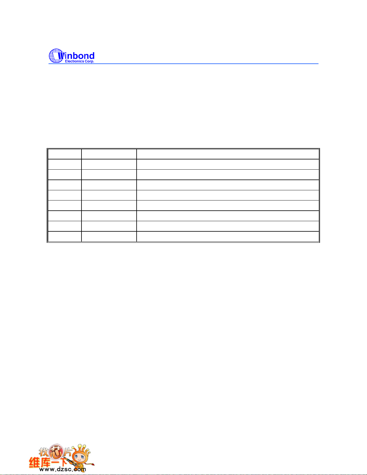
Here is an example to program the P4.0 as a write strobe signal at the I/O port address 1234H
−1237H and positive polarity, and P4.1 − P4.3 are used as general I/O ports.
MOV P40AH, #12H
MOV P40AL, #34H ; Base I/O address 1234H for P4.0
MOV P4CONA, #00001010B ; P4.0 a write strobe signal and address line A0 and A1 are masked.
MOV P4CONB, #00H ; P4.1
MOV P2ECON, #10H ; Write the P40SINV = 1 to inverse the P4.0 write strobe polarity
; default is negative.
Then any instruction MOVX @DPTR, A (with DPTR = 1234H
polarity write strobe signal at pin P4.0. And the instruction MOV P4, #XX will output the bit3 to bit1 of
data #XX to pin P4.3
− P4.1.
− P4.3 as general I/O port which are the same as PORT1
− 1237H) will generate the positive
- 12 -
Page 13
W78E58B/W78E058B
READ
WRITE
ADDRESS BUS
REGISTER
P4xAL
P4xAH
P4 REGISTER
P4.x
REGISTER
P4xCMP0
P4xCMP1
EQUAL
Bit Length
Selectable
comparator
P4xCSINV
DATA I/O
RD_CS
MUX 4->1
WR_CS
RD/WR_CS
PIN
P4.x
P4xFUN0
P4xFUN1
P4.x INPUT DATA BUS
5.12 In-System Programming (ISP) Mode
The W78E058B equips one 32K byte of main ROM bank for application program (called APROM) and
one 4K byte of auxiliary ROM bank for loader program (called LDROM). In the normal operation, the
microcontroller executes the code in the APROM. If the content of APROM needs to be modified, the
W78E058B allows user to activate the In-System Programming (ISP) mode by setting the CHPCON
register. The CHPCON is read-only by default, software must write two specific values 87H,
then 59H sequentially to the CHPENR register to enable the CHPCON write attribute. Writing
CHPENR register with the values except 87H and 59H will close CHPCON register write
attribute. The W78E058B achieves all in-system programming operations including enter/exit ISP
Mode, program, erase, read ... etc, during device in the idle mode. Setting the bit CHPCON.0 the
device will enter in-system programming mode after a wake-up from idle mode. Because device
needs proper time to complete the ISP operations before awaken from idle mode, software may use
timer interrupt to control the duration for device wake-up from idle mode. To perform ISP operation for
revising contents of APROM, software located at APROM setting the CHPCON register then enter idle
mode, after awaken from idle mode the device executes the corresponding interrupt service routine in
LDROM. Because the device will clear the program counter while switching from APROM to LDROM,
the first execution of RETI instruction in interrupt service routine will jump to 00H at LDROM area. The
device offers a software reset for switching back to APROM while the content of APROM has been
updated completely. Setting CHPCON register bit 0, 1 and 7 to logic-1 will result a software reset
to reset the CPU. The software reset serves as a external reset. This in-system programming feature
makes the job easy and efficient in which the application needs to update firmware frequently. In some
Publication Release Date: December 4, 2006
- 13 - Revision A8
Page 14
W78E58B/W78E058B
applications, the in-system programming feature make it possible to easily update the system
firmware without opening the chassis.
SFRAH, SFRAL:
SFRFD:
SFRCN:
SFRCN (C7)
The programming data for on-chip ROM in programming mode.
The control byte of on-chip ROM programming mode.
BIT NAME FUNCTION
7 - Reserve.
6 WFWIN
5 OEN ROM output enable.
4 CEN ROM chip enable.
3, 2, 1, 0 CTRL [3:0] The flash control signals
The objective address of on-chip ROM in the in-system programming mode.
SFRAH contains the high-order byte of address, SFRAL contains the low-order
byte of address.
On-chip ROM bank select for in-system programming.
0: 32K bytes ROM bank is selected as destination for re-programming.
1: 4K bytes ROM bank is selected as destination for re-programming.
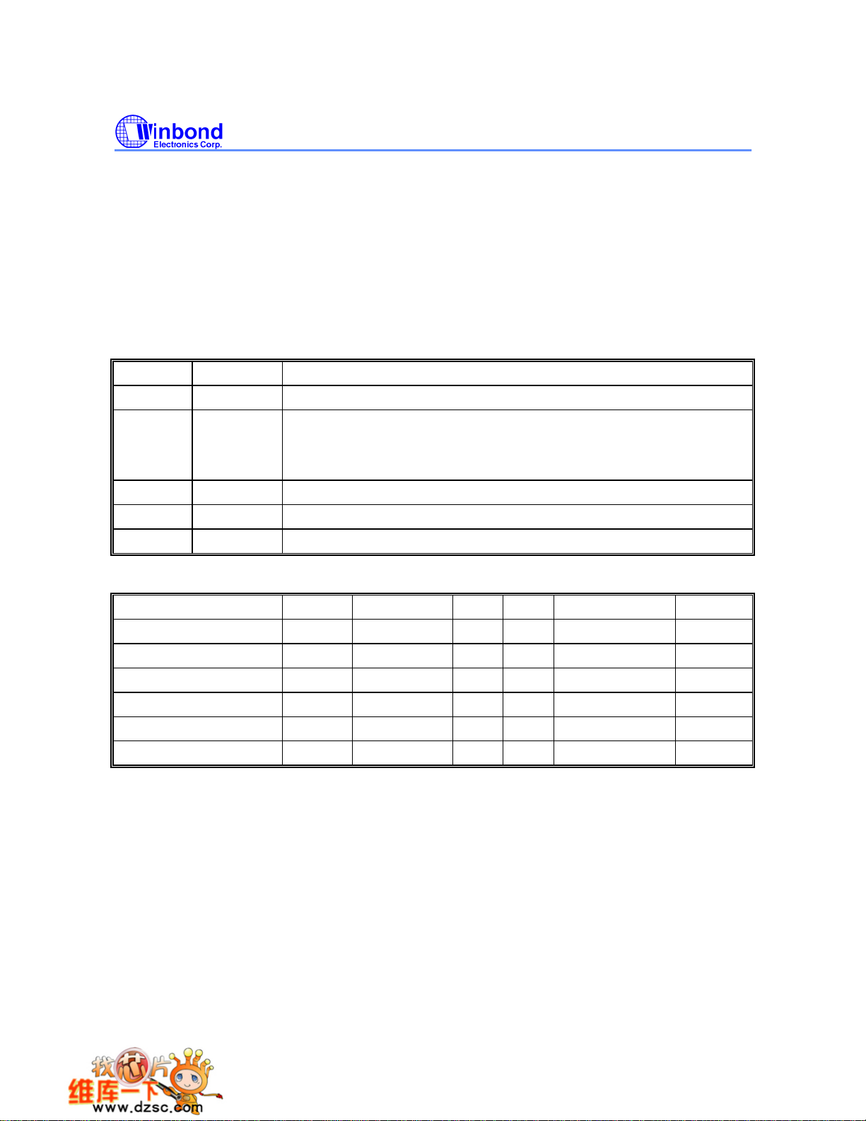
MODE WFWIN CTRL<3:0> OEN CEN SFRAH, SFRAL SFRFD
Erase 32KB APROM 0 0010 1 0 X X
Program 32KB APROM 0 0001 1 0 Address in Data in
Read 32KB APROM 0 0000 0 0 Address in Data out
Erase 4KB LDROM 1 0010 1 0 X X
Program 4KB LDROM 1 0001 1 0 Address in Data in
Read 4KB LDROM 1 0000 0 0 Address in Data out
- 14 -
Page 15

W78E58B/W78E058B
5.13 In-System Programming Control Register (CHPCON)
CHPCON (BFH)
BIT NAME FUNCTION
When this bit is set to 1, and both FBOOTSL and FPROGEN are set to 1. It will
SWRESET
7
(F04KMODE)
6 - Reserve.
5 - Reserve.
enforce microcontroller reset to initial condition just like power on reset. This
action will re-boot the microcontroller and start to normal operation. To read this
bit in logic-1 can determine that the F04KBOOT mode is running.
ENAUXRAM
4
3 0 Must set to 0.
2 0 Must set to 0.
1 FBOOTSL
0 FPROGEN
1: Enable on-chip AUX-RAM.
0: Disable the on-chip AUX-RAM
The Program Location Select.
0: The Loader Program locates at the 32 KB APROM. 4KB LDROM is
destination for re-programming.
1: The Loader Program locates at the 4 KB memory bank. 32KB APROM is
destination for re-programming.
ROM Programming Enable.
1: enable. The microcontroller enter the in-system programming mode after
entering the idle mode and wake-up from interrupt. During in-system
programming mode, the operation of erase, program and read are achieve
when device enters idle mode.
0: disable. The on-chip flash memory is read-only. In-system programmability
is disabled.
5.14 F04KBOOT Mode (Boot From LDROM)
By default, the W78E058B boots from APROM program after a power on reset. On some occasions,
user can force the W78E058B to boot from the LDROM program via following settings. The possible
situation that you need to enter F04KBOOT mode when the APROM program can not run properly
and device can not jump back to LDROM to execute in-system programming function. Then you can
use this F04KBOOT mode to force the W78E058B jumps to LDROM and executes in-system
programming procedure. When you design your system, you may reserve the pins P2.6, P2.7 to
switches or jumpers. For example in a CD-ROM system, you can connect the P2.6 and P2.7 to PLAY
and EJECT buttons on the panel. When the APROM program fails to execute the normal application
program. User can press both two buttons at the same time and then turn on the power of the
personal computer to force the W78E058B to enter the F04KBOOT mode. After power on of personal
computer, you can release both buttons and finish the in-system programming procedure to update
the APROM code.
PSEN pin value at reset to prevent from accidentally activating the programming mode or F04KBOOT
mode.
In application system design, user must take care of the P2, P3, ALE,
EA
and
Publication Release Date: December 4, 2006
- 15 - Revision A8
Page 16

W78E58B/W78E058B
F04KBOOT Mode
P4.3 P2.7 P2.6 MODE
X L L FO4KBOOT
L X X FO4KBOOT
The Reset Timing For Entering
F04KBOOT Mode
P2.7
P2.6
RST
Hi-Z
Hi-Z
30 mS
10 mS
- 16 -
Page 17
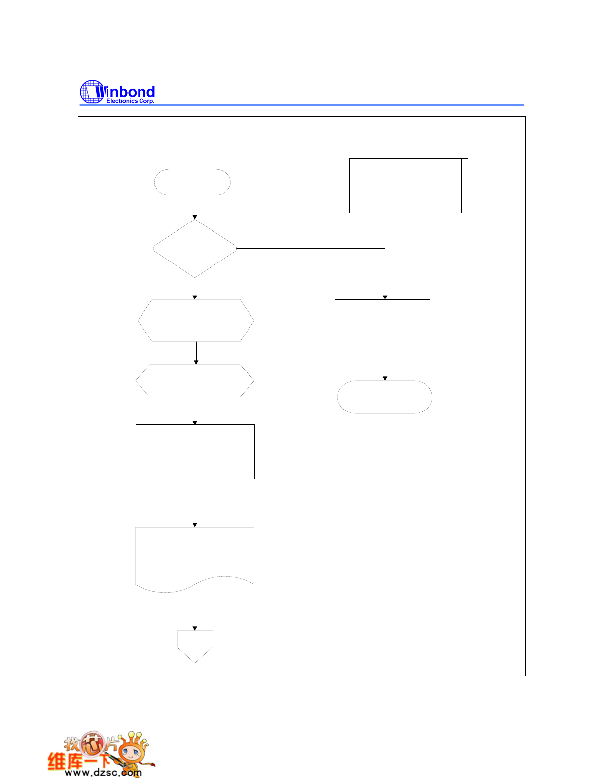
The Algorithm of In-System Programmin
g
START
W78E58B/W78E058B
Part 1:32KB APROM
procedure of entering
In-System Programming Mode
Enter In-System
Programming Mode ?
(conditions depend on
user's application)
Yes
Setting control registers
MOV CHPENR,#87H
MOV CHPENR,#59H
MOV CHPCON,#03H
Setting Timer (about 1.5 us)
and enable timer interrupt
Start Timer and enter idle Mode.
(CPU will be wakened from idle mode
by timer interrupt, then enter In-System
Programming mode)
No
Execute the normal application
program
END
CPU will be wakened by interrupt and
re-boot from 4KB LDROM to execute
the loader program.
Go
Publication Release Date: December 4, 2006
- 17 - Revision A8
Page 18
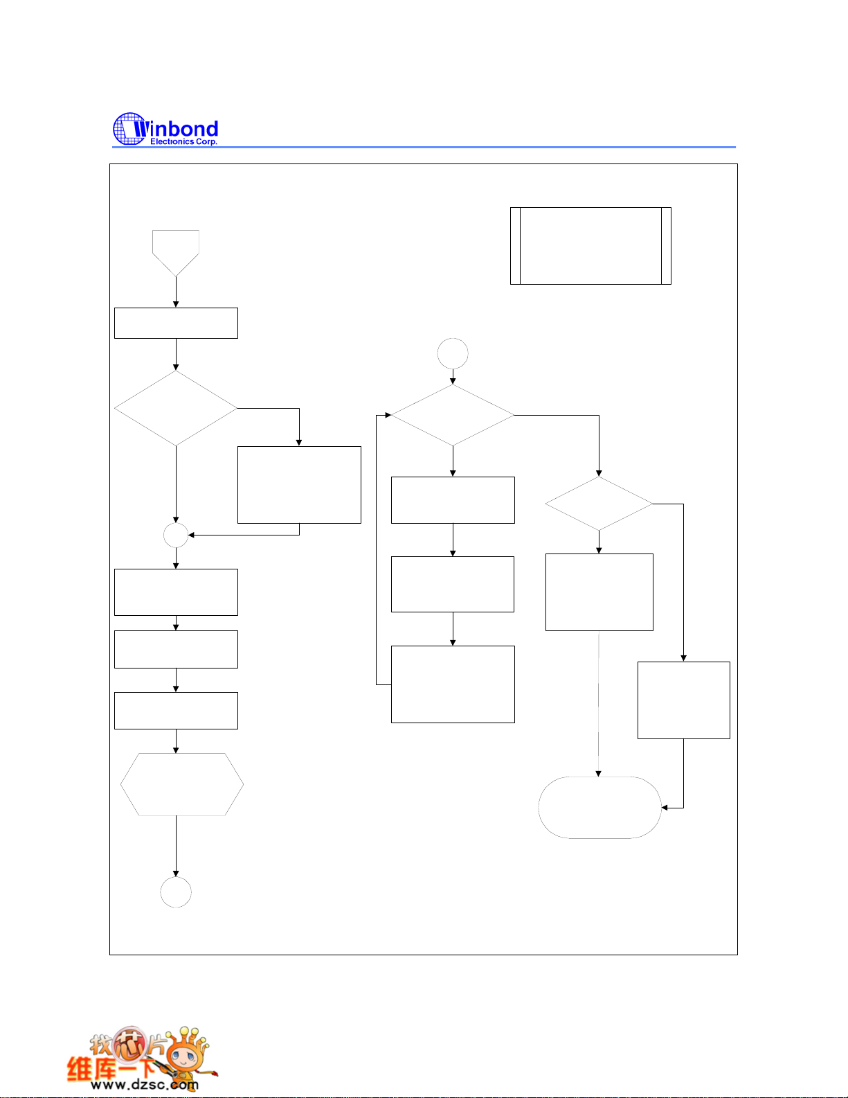
Go
Timer Interrupt Service Routine:
Stop Timer & disable interrupt
W78E58B/W78E058B
Part 2: 4KB LDROM
Procedure of Updating
the 32KB APROM
PGM
Is F04KBOOT Mode?
(CHPCON.7=1)
No
Setting Timer and enable Timer
interrupt for wake-up .
(15 ms for erasing operation)
Setting erase operation mode:
MOV SFRCN,#22H
(Erase 32KB APROM)
Start Timer and enter IDLE
Mode.
(Erasing...)
End of erase
operation. CPU will
be wakened by Timer
interrupt.
Yes
Reset the CHPCON Register:
MOV CHPENR,#87H
MOV CHPENR,#59H
MOV CHPCON,#03H
End of Programming ?
No
Setting Timer and enable Timer
interrupt for wake-up .
(50us for program operation)
Get the parameters of new code
(Address and data bytes)
through I/O ports, UART or
other interfaces.
Setting control registers for
programming:
MOV SFRAH,#ADDRESS_H
MOV SFRAL,#ADDRESS_L
MOV SFRFD,#DATA
MOV SFRCN,#21H
Yes
Is currently in the
F04KBOOT Mode ?
Software reset CPU and
re-boot from the 32KB
APROM.
MOV CHPENR,#87H
MOV CHPENR,#59H
MOV CHPCON,#83H
Executing new code
from address
00H in the 32KB APROM.
END
Yes
No
Hardware Reset
to re-boot from
new 32 KB APROM.
invalid in F04KBOOT
(S/W reset is
Mode)
PGM
- 18 -
Page 19

W78E58B/W78E058B
6. SECURITY
During the on-chip ROM programming mode, the ROM can be programmed and verified repeatedly.
Until the code inside the ROM is confirmed OK, the code can be protected. The protection of ROM
and those operations on it are described below.
The W78E058B has a Security Register that can be accessed in programming mode. Those bits of
the Security Registers can not be changed once they have been programmed from high to low. They
can only be reset through erase-all operation. The Security Register is located at the 0FFFFH of the
LDROM space.
0000h
0FFFh
7FFFh
FFFFh
32KB On-chip ROM
Program Memory
APROM
B0B1
Reserved
B7
B0: Lock bit, logic 0: active
B1: MOVC inhibit,
logic 0: the MOVC instruction in external memory
cannot access the code in internal memory.
logic 1: no restriction.
B2: Encryption
logic 0: the encryption logic enable
logic 1: the encryption logic disable
B07: Osillator Control
logic 0: 1/2 gain
logic 1: Full gain
Default 1 for all security bits.
Reserved bits must be kept in logic 1.
B2
Security Bits
Special Setting Register
4KB On-chip ROM
Program Memory
LDROM
Reserved
Reserved
Security Register
6.1 Lock Bit
This bit is used to protect the customer's program code in the W78E058B. It may be set after the
programmer finishes the programming and verifies sequence. Once this bit is set to logic 0, both the
ROM data and Security Register can not be accessed again.
6.2 MOVC Inhibit
This bit is used to restrict the accessible region of the MOVC instruction. It can prevent the MOVC
instruction in external program memory from reading the internal program code. When this bit is set to
logic 0, a MOVC instruction in external program memory space will be able to access code only in the
external memory, not in the internal memory. A MOVC instruction in internal program memory space
will always be able to access the ROM data in both internal and external memory. If this bit is logic 1,
there are no restrictions on the MOVC instruction.
Publication Release Date: December 4, 2006
- 19 - Revision A8
Page 20

W78E58B/W78E058B
6.3 Encryption
This bit is used to enable/disable the encryption logic for code protection. Once encryption feature is
enabled, the data presented on port 0 will be encoded via encryption logic. Only whole chip erase will
reset this bit.
6.4 Oscillator Control
W78E058B/E516 allow user to diminish the gain of on-chip oscillator amplifier by using programmer to
set the bit B7 of security register. Once B7 is set to 0, a half of gain will be decreased. Care must be
taken if user attempts to diminish the gain of oscillator amplifier, reducing a half of gain may
improperly affect the external crystal operation at high frequency above 24 MHz. The value of R and
C1, C2 may need some adjustment while running at lower gain.
- 20 -
Page 21
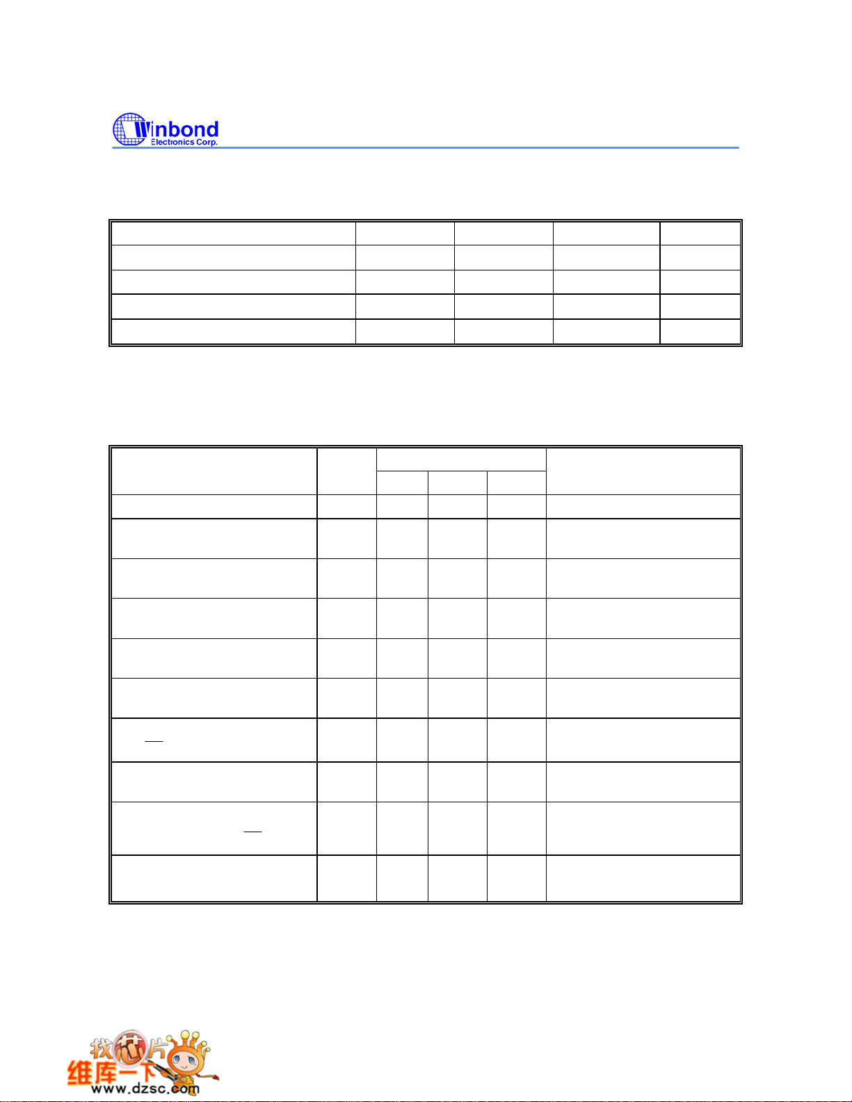
7. ELECTRICAL CHARACTERISTICS
A
7.1 Absolute Maximum Ratings
PARAMETER SYMBOL MIN. MAX. UNIT
W78E58B/W78E058B
DC Power Supply
VDD − VSS
-0.3 +6.0 V
Input Voltage VIN VSS -0.3 VDD +0.3 V
Operating Temperature TA 0 70
Storage Temperature TST -55 +150
Note: Exposure to conditions beyond those listed under Absolute Maximum Ratings may adversely affect the life and reliability
of the device.
°C
°C
7.2 D.C. Characteristics
(VDD−VSS = 5V ±10%, TA = 25° C, Fosc = 20 MHz, unless otherwise specified.)
PARAMETER SYM.
Operating Voltage VDD 4.5 5.5 V RST = 1, P0 = VDD
Operating Current IDD - 20 mA
Idle Current IIDLE - 6 mA
Power Down Current IPWDN - 50
Input Current
P1, P2, P3, P4
IN1 -50 +10
I
SPECIFICATION
MIN. MAX. UNIT
µA
µA
TEST CONDITIONS
No load
DD
= 5.5V
V
Idle mode
DD = 5.5V
V
Power-down mode
V
DD = 5.5V
V
DD = 5.5V
IN = 0V or VDD
V
Input Current
RST
Input Leakage Current
EA
P0,
Logic 1 to 0 Transition Current
P1, P2, P3, P4
Input Low Voltage
E
P0, P1, P2, P3, P4,
Input Low Voltage
RST
V
IN2 -10 +300
I
LK -10 +10
I
[*4]
TL
-500 -
I
µA
µA
µA
DD = 5.5V
0V < V
DD = 5.5V
V
0V < V
V
DD = 5.5V
IN = 2.0V
V
IN < VDD
IN < VDD
VIL1 0 0.8 V VDD = 4.5V
V IL2 0 0.8 V VDD = 4.5V
Publication Release Date: December 4, 2006
- 21 - Revision A8
Page 22

D.C. Characteristics, continued
W78E58B/W78E058B
PARAMETER SYM.
Input Low Voltage
[*4]
XTAL1
Input High Voltage
P0, P1, P2,
P3, P4, EA
Input High Voltage
RST
Input High Voltage
[*4]
XTAL1
Output Low Voltage
P1, P2, P3, P4
Output Low Voltage
P0, ALE,
PSEN
[*3]
Sink current
P1, P3, P4
Sink current
P0, P2, ALE,
PSEN
SPECIFICATION
TEST CONDITIONS
MIN. MAX. UNIT
IL3 0 0.8 V VDD = 4.5V
V
IH1 2.4 VDD +0.2 V VDD = 5.5V
V
IH2 3.5 VDD +0.2 V VDD = 5.5V
V
IH3 3.5 VDD +0.2 V VDD = 5.5V
V
DD = 4.5V
OL1 - 0.45 V
V
V
OL2 - 0.45 V
V
OL = +2 mA
I
DD = 4.5V
V
OL = +4 mA
I
DD = 4.5V
V
Isk1 4 12 mA
IN = 0.45V
V
V
DD = 4.5V
Isk2 10 20 mA
IN = 0.45V
V
V
Output High Voltage
P1, P2, P3, P4
Output High Voltage
P0, ALE,
PSEN
[*3]
Source Current
P1, P2, P3, P4
Source Current
OH1 2.4 - V
V
V
OH2 2.4 - V
Isr1 -120 -250
µA
DD = 4.5V
OH = -100 µA
I
DD = 4.5V
V
OH = -400 µA
I
V
DD = 4.5V
IN = 2.4V
V
DD = 4.5V
V
Isr2 -8 -20 mA
IN = 2.4V
P0, P2, ALE,
Notes:
*1. RST pin is a Schmitt trigger input.
*2. P0, ALE and
*3. XTAL1 is a CMOS input.
*4. Pins of P1, P2, P3, P4 can source a transition current when they are being externally driven from 1 to 0.
PSEN
PSEN are tested in the external access mode.
V
- 22 -
Page 23

W78E58B/W78E058B
7.3 A.C. Characteristics
The AC specifications are a function of the particular process used to manufacture the part, the
ratings of the I/O buffers, the capacitive load, and the internal routing capacitance. Most of the
specifications can be expressed in terms of multiple input clock periods (T
usually experience less than a
±20 nS variation. The numbers below represent the performance
expected from a 0.6 micron CMOS process when using 2 and 4 mA output buffers.
7.3.1 Clock Input Waveform
CP), and actual parts will
XTAL1
T
CH
F
OP,
T
CL
T
CP
PARAMETER SYMBOL MIN. TYP. MAX. UNIT NOTES
Operating Speed FOP 0 - 40 MHz 1
Clock Period TCP 25 - - nS 2
Clock High TCH 10 - - nS 3
Clock Low TCL 10 - - nS 3
Notes:
1. The clock may be stopped indefinitely in either state.
2. The T
3. There are no duty cycle requirements on the XTAL1 input.
CP specification is used as a reference in other specifications.
7.3.2 Program Fetch Cycle
PARAMETER SYMBOL MIN. TYP. MAX. UNIT NOTES
Address Valid to ALE Low TAAS
Address Hold from ALE Low TAAH
APL
ALE Low to PSEN Low
PSEN Low to Data Valid
Data Hold after PSEN High
Data Float after PSEN High
T
PDA - - 2 TCP nS 2
T
T
PDH 0 - 1 TCP nS 3
T
PDZ 0 - 1 TCP nS
ALE Pulse Width TALW
T
PSEN Pulse Width
Notes:
1. P0.0 − P0.7, P2.0 − P2.7 remain stable throughout entire memory cycle.
2. Memory access time is 3 T
3. Data have been latched internally prior to
4. "
∆" (due to buffer driving delay and wire loading) is 20 nS.
CP.
PSW
PSEN going high.
CP-∆
1 T
1 TCP-∆
1 T
CP-∆
CP-∆
2 T
3 T
CP-∆
- - nS 4
- - nS 1, 4
- - nS 4
2 T
CP - nS 4
CP - nS 4
3 T
Publication Release Date: December 4, 2006
- 23 - Revision A8
Page 24
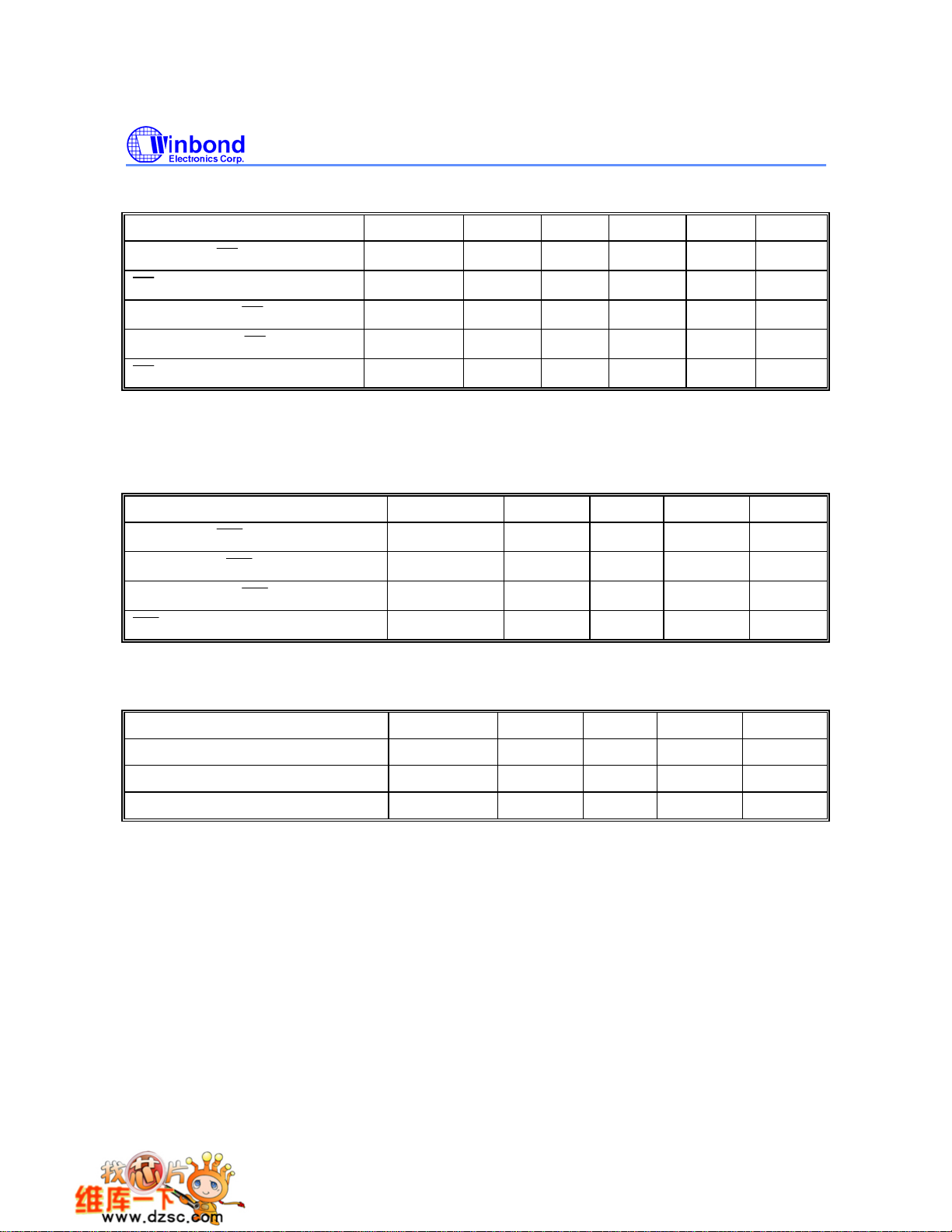
7.3.3 Data Read Cycle
PARAMETER SYMBOL MIN. TYP. MAX. UNIT NOTES
ALE Low to RD Low
RD Low to Data Valid
Data Hold from RD High
Data Float from RD High
RD Pulse Width
Notes:
1. Data memory access time is 8 TCP.
2. "
∆" (due to buffer driving delay and wire loading) is 20 nS.
7.3.4 Data Write Cycle
PARAMETER SYMBOL MIN. TYP. MAX. UNIT
ALE Low to WR Low
W78E58B/W78E058B
T
DAR
T
DDA - - 4 TCP nS 1
T
DDH 0 - 2 TCP nS
T
DDZ 0 - 2 TCP nS
T
DRD
T
DAW
3 T
6 T
CP-∆
CP-∆
3 T
-
3 T
CP+∆
nS 1, 2
6 TCP - nS 2
CP-∆
-
3 TCP+∆
nS
T
T
DWD
T
DWR
DAD
Data Valid to WR Low
Data Hold from WR High
WR Pulse Width
Note: "∆" (due to buffer driving delay and wire loading) is 20 nS.
1 T
1 T
6 T
CP-∆
CP-∆
CP-∆
- - nS
- - nS
CP - nS
6 T
7.3.5 Port Access Cycle
PARAMETER SYMBOL MIN. TYP. MAX. UNIT
Port Input Setup to ALE Low TPDS 1 TCP - - nS
Port Input Hold from ALE Low TPDH 0 - - nS
Port Output to ALE TPDA 1 TCP - - nS
Note: Ports are read during S5P2, and output data becomes available at the end of S6P2. The timing data are referenced to
ALE, since it provides a convenient reference.
- 24 -
Page 25

8. TIMING WAVEFORMS
8.1 Program Fetch Cycle
S1
S2 S3 S4 S5 S6 S1 S2 S3 S4 S5 S6
XTAL1
ALE
PSEN
T
PORT 2
T
AAH
PORT 0
Code
A0-A7
AAS
T
T
APL
T
PDA
PSW
Data
T
ALW
T
PDH,TPDZ
A0-A7
Code
W78E58B/W78E058B
A0-A7
Data
A0-A7
8.2 Data Read Cycle
XTAL1
ALE
PSEN
PORT 2
PORT 0
RD
A0-A7
T
DAR
A8-A15
T
DDA
T
DRD
DATA
T
DDH,TDDZ
S2 S3S5 S6 S1S2 S3 S4S5 S6 S1S4
Publication Release Date: December 4, 2006
- 25 - Revision A8
Page 26
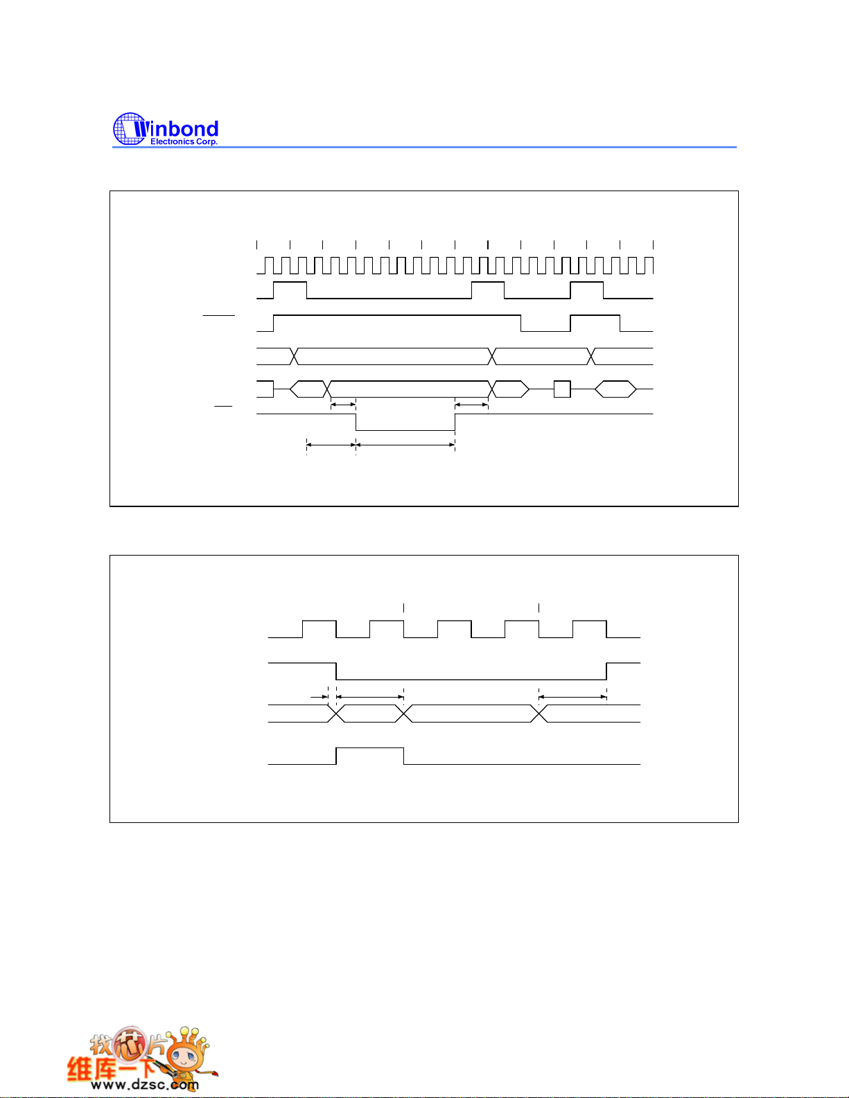
8.3 Data Write Cycle
XTAL1
ALE
PSEN
W78E58B/W78E058B
S2 S3S5 S6 S1S2 S3 S4S1S5 S6S4
PORT 2
PORT 0
WR
8.4 Port Access Cycle
XTAL1
ALE
PORT
INPUT
SAMPLE
A0-A7
T
A8-A15
DATA OUT
T
T
DAD
T
DAW
S5 S6 S1
T
DWR
T
PDHPDS
DWD
T
PDA
DATA OUT
- 26 -
Page 27
W78E58B/W78E058B
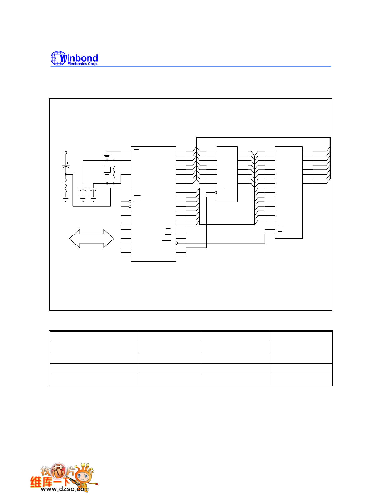
9. TYPICAL APPLICATION CIRCUITS
9.1 Expanded External Program Memory and Crystal
V
8.2 K
DD
10 u
C1
CRYSTAL
C2
31
EA
19
XTAL1
R
18
XTAL2
9
RST
INT0
12
13
INT1
14
T0
15
T1
P1.0 1
P1.1
2
P1.2
3
P1.3
4
P1.4
5
P1.5
6
P1.6
7
P1.7
8
W78E58B/W78E058B
P0.0
P0.1
P0.2
P0.3
P0.4
P0.5
P0.6
P0.7
P2.0
P2.1
P2.2
P2.3
P2.4
P2.5
P2.6
P2.7
WR
PSEN
ALE
TXD
RXD
RD
AD0
39
AD1
38
AD2
37
AD3
36
AD4
35
AD5
34
AD6
33
32
AD7
21
A8
22
A9
23
A10
24
A11
25
A12
26
A13
27
A14
28
A15
17
16
29
30
11
10
AD0
AD1
AD2
AD3
AD4
AD5
AD6
AD7
GND
3
4
7
8
13
14
17
18
1
11
D0
Q0
D1
Q1
D2
Q2
D3
Q3
D4
Q4
D5
Q5
D6
Q6
D7
Q7
OC
G
74LS373
11
A0
A1
A2
A3
A4
A5
A6
A7
A0
A1
A2
A3
A4
A5
A6
A7
A8
A9
A10
A11
A12
A13
A14
A15
GND
10
9
8
7
6
5
4
3
25
24
21
23
2
26
27
1
20
22
A0
A1
A2
A3
A4
A5
A6
A7
A8
A9
A10
A11
A12
A13
A14
A15
CE
OE
27512
O0
O1
O2
O3
O4
O5
O6
O7
2
5
6
9
12
15
16
19
AD0
12
AD1
13
AD2
15
AD3
16
AD4
17
AD5
18
AD6
19
AD7
Figure A
CRYSTAL C1 C2 R
6 MHz 47P 47P -
16 MHz 30P 30P -
24 MHz 15P 10P -
40MHz 5P 5P 6.8K
Above table shows the reference values for crystal applications.
Notes:
1. C1, C2, R components refer to Figure A
2. Crystal layout must get close to XTAL1 and XTAL2 pins on user's application board.
Publication Release Date: December 4, 2006
- 27 - Revision A8
Page 28
W78E58B/W78E058B
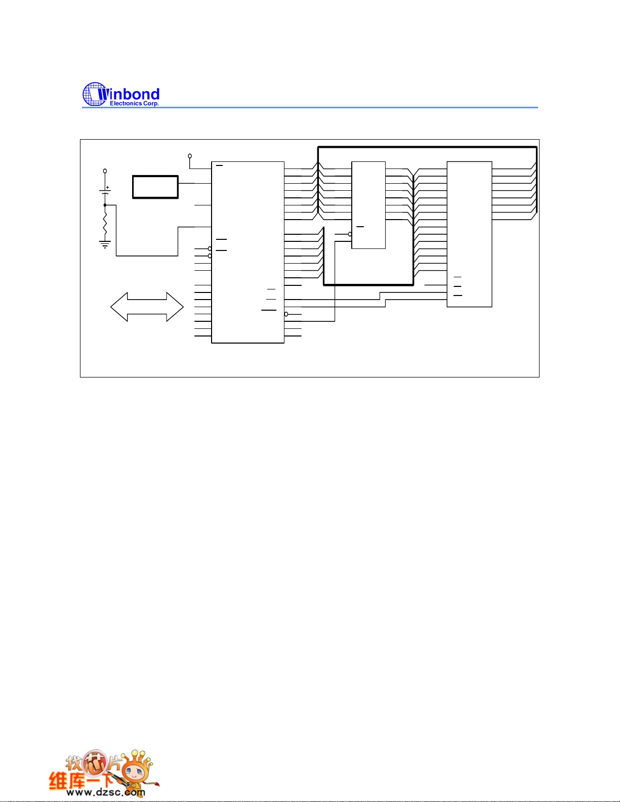
9.2 Expanded External Data Memory and Oscillator
V
DD
V
8.2 K
DD
10 u
OSCILLATOR
31
EA
19
XTAL1
18
XTAL2
9
RST
INT0
12
13
INT1
14
T0
15
T1
1
P1.0
2
P1.1
3
P1.2
4
P1.3
5
P1.4
6
P1.5
7
P1.6
8
P1.7
W78E58B/W78E058B
P0.0
P0.1
P0.2
P0.3
P0.4
P0.5
P0.6
P0.7
P2.0
P2.1
P2.2
P2.3
P2.4
P2.5
P2.6
P2.7
RD
WR
PSEN
ALE
TXD
RXD
AD0
AD1
AD2
AD3
AD4
AD5
AD6
AD7
A8
A9
A10
A11
A12
A13
A14
AD0
AD1
AD2
AD3
AD4
AD5
AD6
AD7
GND
3
4
7
8
13
14
17
18
11
1
D0
D1
D2
D3
D4
D5
D6
D7
OC
G
74LS373
39
38
37
36
35
34
33
32
21
22
23
24
25
26
27
28
17
16
29
30
11
10
Q0
Q1
Q2
Q3
Q4
Q5
Q6
Q7
A0
A1
A2
A3
A4
A5
A6
A7
A8
A9
A10
A11
A12
A13
A14
GND
10
A0
A1
A2
A3
A4
A5
A6
A7
A8
A9
A10
A11
A12
A13
A14
CE
OE
WR
D0
D1
D2
D3
D4
D5
D6
D7
9
8
7
6
5
4
3
25
24
21
23
2
26
1
20
22
27
20256
A0
2
5
A1
A2
6
9
A3
12
A4
15
A5
16
A6
19
A7
AD0
11
AD1
12
AD2
13
15
AD3
AD4
16
AD5
17
AD6
18
AD7
19
Figure B
- 28 -
Page 29

10. PACKAGE DIMENSIONS
10.1 40-pin DIP
40
1
E
1
S
A
2
A
L
D
B
e
1
B
1
W78E58B/W78E058B
Dimension in inchDimension in mm
Symbol
A
1
A
2
A
B
1
B
c
21
D
E
E
1
e
1
L
a
A
e
20
E
Base Plane
1
A
Seating Plane
e
a
A
S
Notes:
1. Dimension D Max. & S include mold flash or
tie bar burrs.
c
2. Dimension E1 does not include interlead flash.
3. Dimension D & E1 include mold mismatch and
are determined at the mold parting line.
4. Dimension B1 does not include dambar
protrusion/intrusion.
5. Controlling dimension: Inches.
6. General appearance spec. should be based on
final visual inspection spec.
Nom.
Min.
0.010
0.150
0.016
0.008
0.540
0.120
015
0.630 16.00
Max. Max.
Min.
0.210
0.160
0.022
0.0540.048
0.014
0.610
0.550
0.110
0.140
0.670
0.090
.
0.254
3.81
0.406
0.203
14.986
13.72
2.286 2.54 2.7940.090 0.100
3.048
0.155
0.018
0.050 1.27
0.010
2.055 2.070
0.6000.590
0.545
0.130
0.650
Nom.
3.937
0.457
0.254
52.20
15.24
13.84
3.302
16.51
5.334
4.064
0.559
1.3721.219
0.356
52.58
15.494
13.97
3.556
150
17.01
2.286
10.2 44-pin PLCC
H
61
7
17
L
θ
Seating Plane
D
e
G
D
44 40
b
b
1
D
Dimension in inch
Symbol
39
H
E
E
G
E
A
A
1
A
2
b
1
b
c
D
E
e
29
2818
c
G
D
G
E
D
H
E
H
L
Min.
0.020
0.145
0.026
0.016
0.008
0.648
0.648
0.590
0.590
0.680
0.680
0.090
Nom.
0.150
0.028
0.018
0.010
0.653
0.653
0.050
0.610
0.690
0.690
0.100
y
2A
A
1
A
y
Notes:
1. Dimension D & E do not include interlead
flash.
2. Dimension b1 does not include dambar
protrusion/intrusion.
3. Controlling dimension: Inches
4. General appearance spec. should be based
on final visual inspection spec.
Dimension in mm
Min.
0.508
3.683
0.66
0.406
0.203
16.46
16.46
14.99
17.27
17.27
2.296
Nom.
3.81
0.711
0.457
0.254
16.59
16.59
1.27
15.49
15.4914.99
17.53
2.54
Max. Max.
0.185
0.155
0.032
0.022
0.014
0.658
0.658
BSC
0.630
0.6300.610
0.700
0.700
0.110
0.004
4.699
3.937
0.813
0.559
0.356
16.71
16.71
BSC
16.00
16.00
17.78
17.7817.53
2.794
0.10
Publication Release Date: December 4, 2006
- 29 - Revision A8
Page 30
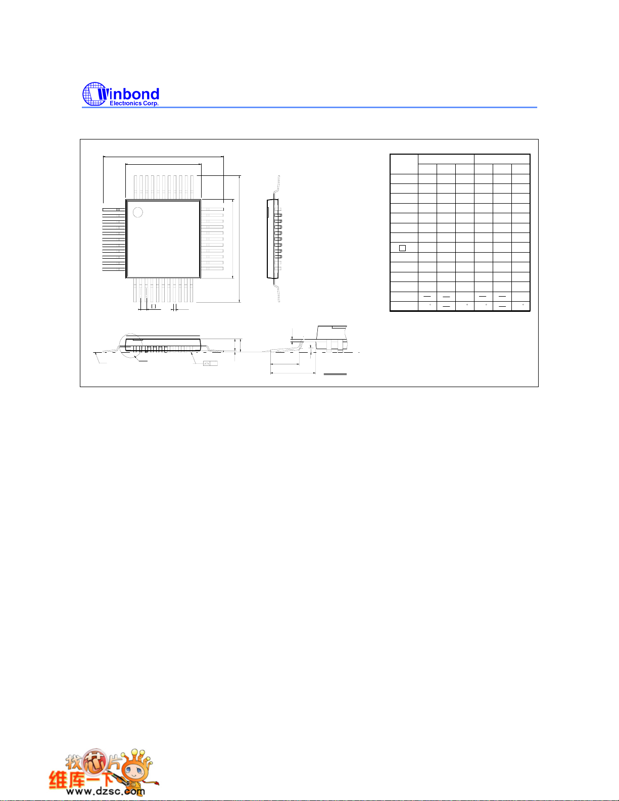
10.3 44-pin PQFP
H
D
D
44
1
11
12
e
Seating Plane
See Detail F
W78E58B/W78E058B
Dimension in inch
34
Symbol
A
1
A
A
33
2
b
c
D
E
EH
E
e
D
H
E
H
L
1
L
22
b
y
θ
Nom.
Min.
--- ---
---
0.01 0.02 0.25
0.002
0.081
0.075
0.01
0.014
0.006 0.152
0.394
0.390
0.390
0.025
0.031
0.510 13.45
0.520
0.520
0.510
0.025
0.031
0.063
0.051
0
Notes:
c
A
A
2
A
1
y
θ
L
L
1
Detail F
1. Dimension D & E do not include interlead
flash.
2. Dimension b does not include dambar
protrusion/intrusion.
3. Controlling dimension: Millimeter
4. General appearance spec. should be based
on final visual inspection spec.
Dimension in mm
Min.
---
0.05
1.90
0.25
9.9
9.9
0.635
12.95
12.95
0.65
0
Nom.
2.05
0.35
10.00
10.00
0.80
13.2
13.2
0.8
1.6
---
0.5
2.20
0.45
0.2540.101
10.1
10.1
0.952
13.45
0.95
1.905
0.08
Max. Max.
---
0.087
0.018
0.0100.004
0.398
0.3980.394
0.036
0.530
0.530
0.037
0.075 1.295
0.003
7
7
- 30 -
Page 31

W78E58B/W78E058B
11. APPLICATION NOTES
11.1 In-system Programming Software Examples
This application note illustrates the in-system programmability of the Winbond W78E058B ROM
microcontroller. In this example, microcontroller will boot from 32KB APROM bank and waiting for a
key to enter in-system programming mode for re-programming the contents of 32KB APROM. While
entering in-system programming mode, microcontroller executes the loader program in 4KB LDROM
bank. The loader program erases the 32KB APROM then reads the new code data from external
SRAM buffer (or through other interfaces) to update the 32KB APROM.
EXAMPLE 1:
;*******************************************************************************************************************
;* Example of 32K APROM program: Program will scan the P1.0. if P1.0 = 0, enters in-system
;* programming mode for updating the content of APROM code else executes the current ROM code.
;* XTAL = 16 MHz
;*******************************************************************************************************************
.chip 8052
.RAMCHK OFF
.symbols
CHPCON EQU BFH
CHPENR EQU F6H
SFRAL EQU C4H
SFRAH EQU C5H
SFRFD EQU C6H
SFRCN EQU C7H
ORG 0H
LJMP 100H ; JUMP TO MAIN PROGRAM
;************************************************************************
;* TIMER0 SERVICE VECTOR ORG = 000BH
;************************************************************************
ORG 00BH
CLR TR0 ; TR0 = 0, STOP TIMER0
MOV TL0, R6
MOV TH0, R7
RETI
;************************************************************************
;* 32K APROM MAIN PROGRAM
;************************************************************************
ORG 100H
MAIN_32K:
MOV A, P1 ; SCAN P1.0
ANL A, #01H
CJNE A, #01H, PROGRAM_32K; IF P1.0 = 0, ENTER IN-SYSTEM PROGRAMMING MODE
JMP NORMAL_MODE
PROGRAM_32K:
MOV CHPENR, #87H ; CHPENR = 87H, CHPCON REGISTER WRTE ENABLE
MOV CHPENR, #59H ; CHPENR = 59H, CHPCON REGISTER WRITE ENABLE
MOV CHPCON, #03H ; CHPCON = 03H, ENTER IN-SYSTEM PROGRAMMING MODE
Publication Release Date: December 4, 2006
- 31 - Revision A8
Page 32

W78E58B/W78E058B
MOV TCON, #00H ; TR = 0 TIMER0 STOP
MOV IP, #00H ; IP = 00H
MOV IE, #82H ; TIMER0 INTERRUPT ENABLE FOR WAKE-UP FROM IDLE MODE
MOV R6, #F0H ; TL0 = F0H
MOV R7, #FFH ; TH0 = FFH
MOV TL0, R6
MOV TH0, R7
MOV TMOD, #01H ; TMOD = 01H, SET TIMER0 A 16-BIT TIMER
MOV TCON, #10H ; TCON = 10H, TR0 = 1, GO
MOV PCON, #01H ; ENTER IDLE MODE FOR LAUNCHING THE IN-SYSTEM
; PROGRAMMING
;********************************************************************************
;* Normal mode 32KB APROM program: depending user's application
;********************************************************************************
NORMAL_MODE:
. ; User's application program
.
.
.
EXAMPLE 2:
;******************************************************************************************************************************
Example of 4 KB LDROM program: This loader program will erase the 32KB APROM first, then reads the new ;*
code from external SRAM and program them into 32 KB APROM bank. XTAL = 16 MHz
;*****************************************************************************************************************************
.chip 8052
.RAMCHK OFF
.symbols
CHPCON EQU BFH
CHPENR EQU F6H
SFRAL EQU C4H
SFRAH EQU C5H
SFRFD EQU C6H
SFRCN EQU C7H
ORG 000H
LJMP 100H ; JUMP TO MAIN PROGRAM
;************************************************************************
;* 1. TIMER0 SERVICE VECTOR ORG = 0BH
;************************************************************************
ORG 000BH
CLR TR0 ; TR0 = 0, STOP TIMER0
MOV TL0, R6
MOV TH0, R7
RETI
;************************************************************************
;* 4KB LDROM MAIN PROGRAM
;************************************************************************
ORG 100H
- 32 -
Page 33

W78E58B/W78E058B
MAIN_4K:
MOV SP, #C0H
MOV CHPENR, #87H ; CHPENR = 87H, CHPCON WRITE ENABLE.
MOV CHPENR, #59H ; CHPENR = 59H, CHPCON WRITE ENABLE.
MOV A, CHPCON
ANL A, #80H
CJNE A, #80H, UPDATE_32K ; CHECK F04KBOOT MODE ?
MOV CHPCON, #03H ; CHPCON = 03H, ENABLE IN-SYSTEM PROGRAMMING.
MOV CHPENR, #00H ; DISABLE CHPCON WRITE ATTRIBUTE
MOV TCON, #00H ; TCON = 00H, TR = 0 TIMER0 STOP
MOV TMOD, #01H ; TMOD = 01H, SET TIMER0 A 16BIT TIMER
MOV IP, #00H ; IP = 00H
MOV IE, #82H ; IE = 82H, TIMER0 INTERRUPT ENABLED
MOV R6, #F0H
MOV R7, #FFH
MOV TL0, R6
MOV TH0, R7
MOV TCON, #10H ; TCON = 10H, TR0 = 1, GO
MOV PCON, #01H ; ENTER IDLE MODE
UPDATE_32K:
MOV CHPENR, #00H ; DISABLE CHPCON WRITE-ATTRIBUTE
MOV TCON, #00H ; TCON = 00H , TR = 0 TIM0 STOP
MOV IP, #00H ; IP = 00H
MOV IE, #82H ; IE = 82H, TIMER0 INTERRUPT ENABLED
MOV TMOD, #01H ; TMOD = 01H, MODE1
MOV R6, #E0H ; SET WAKE-UP TIME FOR ERASE OPERATION, ABOUT 15 mS. DEPENDING
; ON USER'S SYSTEM CLOCK RATE.
MOV R7, #B1H
MOV TL0, R6
MOV TH0, R7
ERASE_P_4K:
MOV SFRCN, #22H ; SFRCN(C7H) = 22H ERASE 32K
MOV TCON, #10H ; TCON = 10H, TR0 = 1,GO
MOV PCON, #01H ; ENTER IDLE MODE (FOR ERASE OPERATION)
;*********************************************************************
;* BLANK CHECK
;*********************************************************************
MOV SFRCN, #0H ; READ 32KB APROM MODE
MOV SFRAH, #0H ; START ADDRESS = 0H
MOV SFRAL, #0H
MOV R6, #FEH ; SET TIMER FOR READ OPERATION, ABOUT 1.5 µS.
MOV R7, #FFH
MOV TL0, R6
MOV TH0, R7
BLANK_CHECK_LOOP:
SETB TR0 ; ENABLE TIMER 0
MOV PCON, #01H ; ENTER IDLE MODE
MOV A, SFRFD ; READ ONE BYTE
CJNE A, #FFH, BLANK_CHECK_ERROR
Publication Release Date: December 4, 2006
- 33 - Revision A8
Page 34

W78E58B/W78E058B
INC SFRAL ; NEXT ADDRESS
MOV A, SFRAL
JNZ BLANK_CHECK_LOOP
INC SFRAH
MOV A, SFRAH
CJNE A, #80H, BLANK_CHECK_LOOP ; END ADDRESS = 7FFFH
JMP PROGRAM_32KROM
BLANK_CHECK_ERROR:
MOV P1, #F0H
MOV P3, #F0H
JMP $
;*******************************************************************************
;* RE-PROGRAMMING 32KB APROM BANK
;*******************************************************************************
PROGRAM_32KROM:
MOV DPTR, #0H ; THE ADDRESS OF NEW ROM CODE
MOV R2, #00H ; TARGET LOW BYTE ADDRESS
MOV R1, #00H ; TARGET HIGH BYTE ADDRESS
MOV DPTR, #0H ; EXTERNAL SRAM BUFFER ADDRESS
MOV SFRAH, R1 ; SFRAH, TARGET HIGH ADDRESS
MOV SFRCN, #21H ; SFRCN(C7H) = 21 (PROGRAM 32K)
MOV R6, #BEH ; SET TIMER FOR PROGRAMMING, ABOUT 50 µS.
MOV R7, #FFH
MOV TL0, R6
MOV TH0, R7
PROG_D_32K:
MOV SFRAL, R2 ; SFRAL(C4H) = LOW BYTE ADDRESS
MOVX A, @DPTR ; READ DATA FROM EXTERNAL SRAM BUFFER. BY ACCORDING USER?
; CIRCUIT, USER MUST MODIFY THIS INSTRUCTION TO FETCH CODE
MOV SFRFD, A ; SFRFD(C6H) = DATA IN
MOV TCON, #10H ; TCON = 10H, TR0 = 1,GO
MOV PCON, #01H ; ENTER IDLE MODE (PRORGAMMING)
INC DPTR
INC R2
CJNE R2, #0H, PROG_D_32K
INC R1
MOV SFRAH, R1
CJNE R1, #80H, PROG_D_32K
;*****************************************************************************
; * VERIFY 32KB APROM BANK
;*****************************************************************************
MOV R4, #03H ; ERROR COUNTER
MOV R6, #FEH ; SET TIMER FOR READ VERIFY, ABOUT 1.5 µS.
MOV R7, #FFH
MOV TL0, R6
MOV TH0, R7
MOV DPTR, #0H ; The start address of sample code
MOV R2, #0H ; Target low byte address
MOV R1, #0H ; Target high byte address
MOV SFRAH, R1 ; SFRAH, Target high address
MOV SFRCN, #00H ; SFRCN = 00 (Read ROM CODE)
- 34 -
Page 35

W78E58B/W78E058B
READ_VERIFY_32K:
MOV SFRAL, R2 ; SFRAL(C4H) = LOW ADDRESS
MOV TCON, #10H ; TCON = 10H, TR0 = 1,GO
MOV PCON, #01H
INC R2
MOVX A, @DPTR
INC DPTR
CJNE A, SFRFD, ERROR_32K
CJNE R2, #0H, READ_VERIFY_32K
INC R1
MOV SFRAH, R1
CJNE R1, #80H, READ_VERIFY_32K
;******************************************************************************
;* PROGRAMMING COMPLETLY, SOFTWARE RESET CPU
;******************************************************************************
MOV CHPENR, #87H ; CHPENR = 87H
MOV CHPENR, #59H ; CHPENR = 59H
MOV CHPCON, #83H ; CHPCON = 83H, SOFTWARE RESET.
ERROR_32K:
DJNZ R4, UPDATE_32K ; IF ERROR OCCURS, REPEAT 3 TIMES.
. ; IN-SYSTEM PROGRAMMING FAIL, USER'S PROCESS TO DEAL WITH IT.
.
.
.
Publication Release Date: December 4, 2006
- 35 - Revision A8
Page 36
W78E58B/W78E058B
12. REVISION HISTORY
VERSION DATE PAGE DESCRIPTION
A3 March, 2002 - Formerly issued
A4 June, 2004 2 Revise part number in the item of packages
A5 April 20, 2005 34 Add Important Notice
A6 June 7, 2005 3 Add Lead Free (RoHS) parts
A7 October 3, 2006 Remove block diagram
A8 December 4, 2006 3 Remove all Leaded package parts
Important Notice
Winbond products are not designed, intended, authorized or warranted for use as components
in systems or equipment intended for surgical implantation, atomic energy control
instruments, airplane or spaceship instruments, transportation instruments, traffic signal
instruments, combustion control instruments, or for other applications intended to support or
sustain life. Further more, Winbond products are not intended for applications wherein failure
of Winbond products could result or lead to a situation wherein personal injury, death or
severe property or environmental damage could occur.
Winbond customers using or selling these products for use in such applications do so at their
own risk and agree to fully indemnify Winbond for any damages resulting from such improper
use or sales.
Headquarters
No. 4, Creation Rd. III,
Science-Based Industrial Park,
Hsinchu, Taiwan
TEL: 886-3-5770066
FAX: 886-3-5665577
http://www.winbond.com.tw/
Taipei Office
9F, No.480, Rueiguang Rd.,
Neihu District, Taipei, 114,
Taiwan, R.O.C.
TEL: 886-2-8177-7168
FAX: 886-2-8751-3579
Please note that all data and specifications are subject to change without notice.
All the trademarks of products and companies mentioned in this datasheet belong to their respective owners.
Winbond Electronics Corporation America
2727 North First Street, San Jose,
CA 95134, U.S.A.
TEL: 1-408-9436666
FAX: 1-408-5441798
Winbond Electronics Corporation Japan
7F Daini-ueno BLDG, 3-7-18
Shinyokohama Kohoku-ku,
Yokohama, 222-0033
TEL: 81-45-4781881
FAX: 81-45-4781800
Winbond Electronics (Shanghai) Ltd.
27F, 2299 Yan An W. Rd. Shanghai,
200336 China
TEL: 86-21-62365999
FAX: 86-21-62365998
Winbond Electronics (H.K.) Ltd.
Unit 9-15, 22F, Millennium City,
No. 378 Kwun Tong Rd.,
Kowloon, Hong Kong
TEL: 852-27513100
FAX: 852-27552064
- 36 -
 Loading...