

Datasheet W78C54M-24, W78C54M-16, W78C54F-40, W78C54F-24, W78C54F-16 Datasheet (Winbond Electronics)
...Page 1

W78C54
8-BIT MICROCONTROLLER
GENERAL DESCRIPTION
The W78C54 is a derivative of the W78C52 microcontroller family that provides extended internal
ROM. The chip has 16K bytes of mask ROM and 256 bytes of RAM.
This device provides an enhanced architecture that makes it more powerful and suitable for a variety
of applications for general control systems. It provides on-chip 16KB mask ROM to accommodate
large program codes, 256-bytes of non-volatile on-chip RAM, four 8-bit I/O ports, one 4-bit I/O port,
three 16-bit timer/counters, eight sources with two-level interrupt structures, and on-chip oscillator
clock circuits.
FEATURES
• DC to 40 MHz extensive operating frequency
• 256-byte on-chip scratch pad RAM
• 16K-byte on-chip mask ROM
• 64K-byte address space for external Program Memory
• 64K-byte address space for external Data Memory
• Three 16-bit timer/counters
• Four 8-bit bit-addressable I/O ports
• One extra 4-bit bit-addressable I/O port, additional INT2/ INT3
(Available on 44-pin PLCC/QFP package)
• Eight-source, two priority-level interrupts
• Low EMI emission mode
• Built-in programmable power-saving modes - Idle mode & Power-down mode
• Packages:
− DIP 40: W78C54-16/24/40
− PLCC 44: W78C54P-16/24/40
− QFP 44: W78C54F-16/24/40
− TQFP 44: W78C54M-16/24/40
Publication Release Date: December 1997
- 1 - Revision A2
Page 2

PIN CONFIGURATIONS
40-Pin DIP (W78C54)
T2, P1.0
T2EX, P1.1
P1.2
P1.3
P1.4
P1.5
P1.6
P1.7
RST
RXD, P3.0
TXD, P3.1
INT0, P3.2
INT1, P3.3
T0, P3.4
T1, P3.5
WR, P3.6
RD, P3.7
XTAL2
XTAL1
VSS
W78C54
VCC1
2
3
4
5
6
7
8
9
10
11
12
13
14
15
16
17
18
19
20
40
39
P0.0, AD0
38
P0.1, AD1
37
P0.2, AD2
P0.3, AD3
36
35
P0.4, AD4
34
P0.5, AD5
P0.6, AD6
33
32
P0.7, AD7
31
EA
ALE
30
29
PSEN
28
P2.7, A15
P2.6, A14
27
26
P2.5, A13
25
P2.4, A12
24
P2.3, A11
23
P2.2, A10
P2.1, A9
22
21
P2.0, A8
44-Pin PLCC (W78C54P)
T
2
E
X
,
P
P
P
P
1
1
1
1
.
.
.
.
1
2
3
4
6 5 4 3
7
P1.5
8
P1.6
9
P1.7
10
RST
RXD, P3.
INT2, P4.3
TXD, P3.1
INT0, P3.2
INT1, P3.3
T0, P3.4
T1, P3.5
11
12
13
14
15
16
17
X
X
P
P
T
T
3
3
A
A
.
.
L
L
7
6
1
2
,
,
/
/
R
W
D
R
/
I
A
N
T
D
T
2
0
3
,
,
,
P
P
P
1
V
0
4
.
C
.
.
0
C
0
2
2 1 44 43 42
V
P
P
P
S
2
2
4
S
.
.
.
1
0
0
,
,
A
A
9
8
44-Pin QFP/TQFP (W78C54F/W78C54M)
/
T
I
2
A
A
A
D
D
D
3
2
1
,
,
,
P
P
P
0
0
0
.
.
.
3
2
1
40
41
P
P
2
2
.
.
3
2
,
,
A
A
1
1
1
0
P0.4, AD4
39
38
P0.5, AD5
37
P0.6, AD6
36
P0.7, AD7
35
EA
34
P4.1
33
ALE
32
PSEN
31
P2.7, A15
30
P2.6, A14
29
P2.5, A13
2827262524232221201918
P
2
.
4
,
A
1
2
P1.5
P1.6
P1.7
RST
RXD, P3.0
INT2, P4.3
TXD, P3.1
INT0, P3.2
INT1, P3.3
T0, P3.4
T1, P3.5
1
2
3
4
5
6
7
8
9
10
11
P
1
.
4
P
3
.
6
,
/
W
R
P
1
.
3
43 42 41
P
3
.
7
,
/
R
D
E
X
,
P
P
1
1
.
.
2
1
X
X
T
T
A
A
L
L
1
2
N
T
T
2
3
,
,
P
P
1
V
4
.
C
.
0
C
2
40 39 38 37 36
V
P
P
S
2
4
S
.
.
0
0
,
A
8
A
A
A
A
D
D
D
D
3
1
2
0
,
,
,
,
P
P
P
P
0
0
0
0
.
.
.
.
3
1
2
0
34
3544
P
P
P
2
2
2
.
.
.
3
1
2
,
,
,
A
A
A
1
1
9
1
0
P0.4, AD4
33
32
P0.5, AD5
31
P0.6, AD6
30
P0.7, AD7
29
EA
28
P4.1
27
ALE
26
PSEN
25
P2.7, A15
24
P2.6, A14
23
P2.5, A13
2221201918171615141312
P
2
.
4
,
A
1
2
- 2 -
Page 3

W78C54
PIN DESCRIPTION
SYMBOL TYPE DESCRIPTIONS
EA I EXTERNAL ACCESS ENABLE: This pin forces the processor to execute out
of external ROM. The ROM address and data will not be present on the bus if
the EA pin is high and the program counter is within the 16 KB area.
Otherwise they will be present on the bus.
PSEN O H
ALE O H ADDRESS LATCH ENABLE: ALE is used to enable the address latch that
RST I L RESET: A high on this pin for two machine cycles while the oscillator is
XTAL1 I CRYSTAL 1: This is the crystal oscillator input. This pin may be driven by an
XTAL2 O CRYSTAL 2: This is the crystal oscillator output. It is the inversion of XTAL1.
VSS I GROUND: ground potential.
VDD I POWER SUPPLY: Supply voltage for operation.
P0.0−P0.7
P1.0−P1.7
P2.0−P2.7
P3.0−P3.7
I/O D PORT 0: Function is the same as that of the standard 8052.
I/O H PORT 1: Function is the same as that of the standard 8052.
I/O H PORT 2: Function is the same as that of the standard 8052.
I/O H PORT 3: Function is the same as that of the standard 8052.
PROGRAM STORE ENABLE: PSEN enables the external ROM data in the
Port 0 address/data bus.
When internal ROM access is performed, no PSEN strobe signal outputs
originate from this pin.
separates the address from the data on Port 0. ALE runs at 1/6th of the
oscillator frequency. An ALE pulse is omitted during external data memory
accesses.
running resets the device.
external clock.
P4.0−P4.3
INT2 (P4.3) I H External interrupt 2: An extra interrupt input source. It cascades to pin P4.3
INT3 (P4.2) I H External interrupt 3: An extra interrupt input source. It cascades to pin P4.2
* Note : TYPE I: input, O: output, I/O: bi-directional, H: pull-high, L: pull-low, D: open drain
I/O H PORT 4: A 4-bit bi-directional parallel port and bit-addressable with internal
pull-ups. Pin P4.3 and P4.2 have alternative function as external interrupt
(INT2/INT3) source input.
internally.
internally.
Publication Release Date: December 1997
- 3 - Revision A2
Page 4
BLOCK DIAGRAM
W78C54
P1.0
~
P1.7
P3.0
~
P3.7
P4.0
~
P4.3
INT2
INT3
Port
1
Port
3
Port
4
Port 1
Latch
Interrupt
Timer
Timer
Timer
UART
Port 3
Latch
Port 4
Latch
ACC
2
Oscillator
PSW
Instruction
Decoder
&
Sequencer
Bus & Clock
Controller
ALU
SFR RAM
RAM & SFR
Reset Block
0
1
T2T1
Address
256 bytes
B
Stack
Pointer
Power control
Port 0
Latch
DPTR
Temp Reg.
PC
Incrementor
Addr. Reg.
16KB
ROM
Port 2
Latch
Port
0
Port
2
P0.0
~
P0.7
P2.0
~
P2.7
XTAL1 PSENALE GNDVCCRSTXTAL2
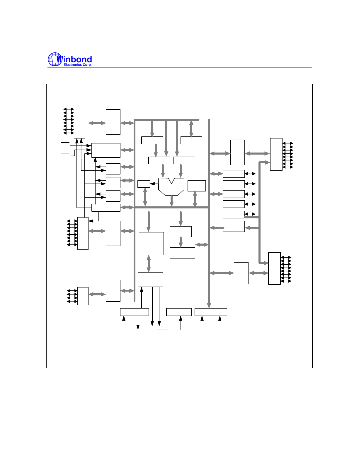
Figure 2. Architecture of the W78C54
- 4 -
Page 5

W78C54
FUNCTIONAL DESCRIPTION
The W78C54 is pin-to-pin compatible with the W78C52, except that the internal 8K mask ROM has
been replaced with 16K of internal mask ROM. The processor supports 111 different opcodes and
references both 64K program address space and 64K data storage space.
Clock
The W78C54 is designed to be used with either a crystal oscillator or an external clock. Internally, the
clock is divided by two before it is used. This makes the W78C54 relatively insensitive to duty cycle
variations in the clock.
Crystal Oscillator
The W78C54 incorporates a built-in crystal oscillator. To make the oscillator work, a crystal is
connected across pins XTAL1 and XTAL2. In addition, a load capacitance of 30 pf (typically) must be
connected from each pin to ground. Resistor must also be connected from XTAL1 to XTAL2 to
provide a DC bias when the crystal frequency is above 24 MHz.
External Clock
An external clock should be connected to pin XTAL1. Pin XTAL2 should be left unconnected. The
XTAL1 input is a CMOS-type input, as required by the crystal oscillator. As a result, the external clock
signal should have an input one level greater than 3.5 volts.
Power Management
Idle Mode
The idle mode is entered by setting the IDLE bit in the PCON register. In the idle mode, the internal
clock to the processor is stopped. The peripherals and the interrupt logic continue to be clocked. The
processor will exit idle mode when either an interrupt or a reset occurs.
Power-down Mode
When the PD bit of the PCON register is set, the processor enters the power-down mode. In this
mode all of the clocks are stopped, including the oscillator. The only way to exit power-down mode is
by a reset.
Reset
The external RESET signal is sampled at S5P2. To take effect, it must be held high for at least two
machine cycles while the oscillator is running.
An internal trigger circuit in the reset line is used to deglitch the reset line when the W78C54 is used
with an external RC network. The reset logic also has a special glitch removal circuit that ignores
glitches on the reset line.
During reset, the ports are initialized to FFH, the stack pointer to 07H, PCON (with the exception of
bit 4) to 00H, and all of the other SFR registers except SBUF to 00H. SBUF is not reset.
New Defined Peripheral
In order to be more suitable for I/O, an extra 4-bit bit-addressable port P4 and two external interrupt
INT2, INT3 has been added to either the PLCC or QFP 44 pin package. And description follows:
Publication Release Date: December 1997
- 5 - Revision A2
Page 6

W78C54
1. INT2 / INT3
Two additional external interrupts, INT2 and INT3, whose functions are similar to those of external
interrupt 0 and 1 in the standard 80C52. The functions/status of these interrupts are
determined/shown by the bits in the XICON (External Interrupt Control) register. The XICON register
is bit-addressable but is not a standard register in the standard 80C52. Its address is at 0C0H. To
set/clear bits in the XICON register, one can use the "SETB (/CLR) bit" instruction. For example,
"SETB 0C2H" sets the EX2 bit of XICON.
2. PORT4
Another bit-address port P4 is also available except only 4 bits (P4<3:0>) can be used. This port
address is located at 0D8H with the same function as that of port P1,except the P4.3 and P4.2 are
alternative function pins. It can be used as general I/O pins or external interrupt input sources
(INT2/INT3).
Example:
P4 REG 0D8H
MOV P4, #0AH ; Output data "A" through P4.0−P4.3.
MOV A, P4 ; Read P4 status to Accumulator.
SETB P4.0 ; Set bit P4.0
CLR P4.1 ; Clear bit P4.1
Reduce EMI Emission
Because of the large on-chip mask-ROM, when a program is running in internal ROM space, the ALE
will be unused. The transition of ALE will cause noise, so it can be turned off to reduce the EMI
emission if it is useless. Turning off the ALE signal transition only requires setting the bit 0 of the
AUXR SFR, which is located at 08Eh. When ALE is turned off, it will be reactivated when the program
accesses external ROM/RAM data or jumps to execute an external ROM code. The ALE signal will
turn off again after it has been completely accessed or the program returns to internal ROM code
space..
POF Flag
The Power-Off-Reset flag is set by on-chip circuitry when the VCC level rises from 0 to 5V. The POF
bit can be set/cleared by software allowing a user to determine if the reset is the result of a power-on
or a warm up by external reset. To avoid effect of POF flag, the power voltage must remain above
3V.
Timers 0, 1, and 2
Timers 0, 1, and 2 each consist of two 8-bit data registers. These are called TL0 and TH0 for Timer 0,
TL1 and TH1 for Timer 1, and TL2 and TH2 for Timer 2. The TCON and TMOD registers provide
control functions for timers 0, 1. The T2CON register provides control functions for Timer 2. RCAP2H
and RCAP2L are used as reload/capture registers for Timer 2.
The operations of Timer 0 and Timer 1 are the same as in the W78C51. Timer 2 is a special feature
of the W78C52C: it is a 16-bit timer/counter that is configured and controlled by the T2CON register.
Like Timers 0 and 1, Timer 2 can operate as either an external event counter or as an internal timer,
depending on the setting of bit C/T2 in T2CON. Timer 2 has three operating modes: capture, autoreload, and baud rate generator. The clock speed at capture or auto-reload mode is the same as that
of Timers 0 and 1.
- 6 -
Page 7

DESCRIPTIONS OF THE SPECIAL FUNCTION REGISTERS (SFRS)
W78C54
SYM. DEFINITION
B B register F0H (F7) (F6) (F5) (F4) (F3) (F2) (F1) (F0) 00000000B
ACC Accumulator E0H (E7) (E6) (E5) (E4) (E3) (E2) (E1) (E0) 00000000B
P4* Port 4 D8H - - - - (DB)
PSW Program status word D0H (D7)CY(D6)AC(D5)F0(D4)
TH2 T2 reg. high CDH 00000000B
TL2 T2 reg. low CCH 00000000B
RCAP2H T2 capture high CBH 00000000B
RCAP2L T2 capture low CAH 00000000B
T2CON Timer 2 control C8H (CF)
XICON* External interrupt
control
IP Interrupt priority B8H - - PT2 PS PT1 PX1 PT0 PX0 xx000000B
P3 Port 3 B0H (B7)RD(B6)WR(B5)T1(B4)T0(B3)
IE Interrupt enable A8H (AF)EA(AE)-(AD)
P2 Port 2 A0H (A7)
SBUF Serial buffer 99H xxxxxxxxB
SCON* Serial control 98H (9F)
P1* Port 1 90H (97) (96) (95) (94) (93) (92) (91)
AUXR* Auxiliary 8EH - - - - - - - AO xxxxxxx0B
TH1 Timer high 1 8DH 00000000B
TH0 Timer high 0 8CH 00000000B
TL1 Timer low 1 8BH 00000000B
TL0 Timer low 0 8AH 00000000B
TMOD Timer mode 89H GATE C/T M1 M0 GATE C/T M1 M0 00000000B
TCON Timer control 88H (8F)
PCON* Power control 87H SMOD
DPH Data pointer high 83H 00000000B
DPL Data pointer low 82H 00000000B
SP Stack pointer 81H 00000111B
P0 Port 0 80H (87) (86) (85) (84) (83) (82) (81) (80) 11111111B
ADDR.
TF2
C0H (C7)
PX3
A15
SM0/FE
TF1
MSB BIT ADDRESS, SYMBOL LSB RESET
(CE)
EXF2
(C6)
EX3
(A6)
A14
(9E)
SM1
(8E)
TR1
SMOD0
(DA)
INT2
(D3)
RS1
RS0
(CD)
(CC)
(CB)
RCLK
TCLK
EXEN2
(C5)
(C4)
(C3)
IE3
ET2
(A5)
A13
(9D)
SM2
(8D)
TF0
IT3
PX2
INT1
(AC)ES(AB)
ET1
(A4)
(A3)
A12
(9C)
(9B)
REN
- POF+ GF1 GF0 PD IDL 00xxxx00B
(8C)
TR0
TB8
(8B)
A11
IE1
INT3
(D2)OV(D1)-(D0)P00000000B
(CA)
TR2
(C2)
EX2
(B2)
INT0
(AA)
EX1
(A2)
A10
(9A)
RB8
(8A)
(D9) (D8) xxxx0000B
(C9)
C/T2
(C1)
IE2
(B1)
TXD
(A9)
ET0
(A1)A9(A0)A811111111B
(99)TI(98)RI00000000B
T2EX
(89)
IT1
IE0
(C8)
CP/RL2
(C0)
IT2
(B0)
RXD
(A8)
EX0
(90)T211111111B
(88)
IT0
00000000B
00000000B
11111111B
00000000B
00000000B
Publication Release Date: December 1997
- 7 - Revision A2
Page 8
W78C54
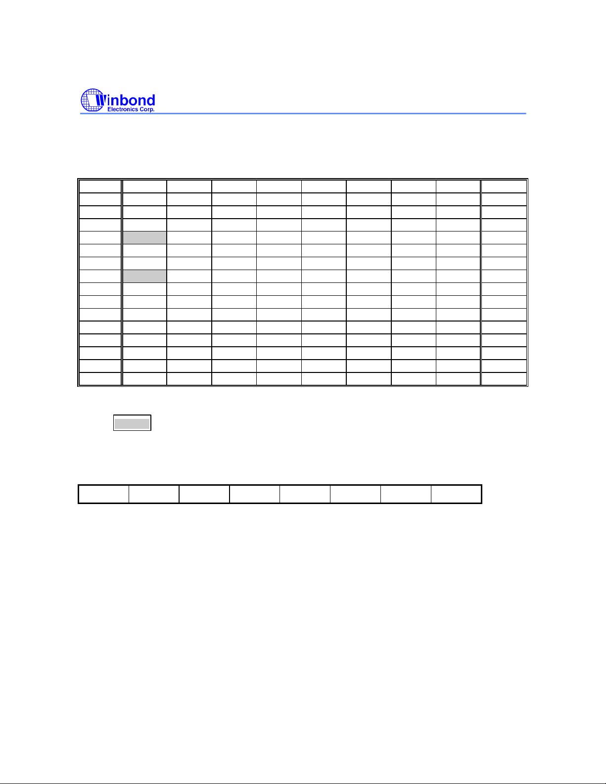
Note: In column BIT_ADDRESS, SYMBOL, containing ( ) item means the bit address.
* SFRs modified or added to the W78C52. + Reset value depends on reset condition.
W78C54 SFRs address location map:
F8 FF
F0 + B F7
E8 EF
E0 + ACC E7
D8 +P4 DF
D0 + PSW D7
C8 +T2CON RCAP2L RCAP2H TL2 TH2 CF
C0 +XICON C7
B8 + IP BF
B0 + P3 B7
A8 + IE AF
A0 + P2 A7
98 + SCON SBUF 9F
90 + P1 97
88 + TCON TMOD TL0 TL1 TH0 TH1 AUXR 8F
80 +P0 SP DPL DPH PCON 87
Notes:
1. + SFR is bit-addressable.
2. is additional defined function.
Power-off Flag
***PCON - Power Control (87H)
SMOD SMOD0
-
POF
SMOD: Double baud rate bit. When set to a 1, the baud rate is doubled when the serial port is
being used in either modes 1, 2, 3.
SMOD0: Enable FE bit in SCON. This bit is an alternative switch of SM0 and FE (Frame Error)
bit. When set to a 1, SCON.7 means a FE bit, otherwise a SM0 bit.
POF: Power off flag. Bit is set by hardware when power on reset. It can be cleared by software
to determine chip reset is a warm boot or cold boot.
GF1, GF0: These two bits are general-purpose flag bits for the user.
PD: Power down mode bit. Set it to enter power down mode.
IDL: Idle mode bit. Set it to enter idle mode.
The power-off flag is located at PCON.4. This bit is set when VDD has been applied to the part. It can
be used to determine if a reset is a warm boot or a cold boot if it is subsequently reset by software.
GF1 GF0 PD IDL
- 8 -
Page 9
* Interrupts
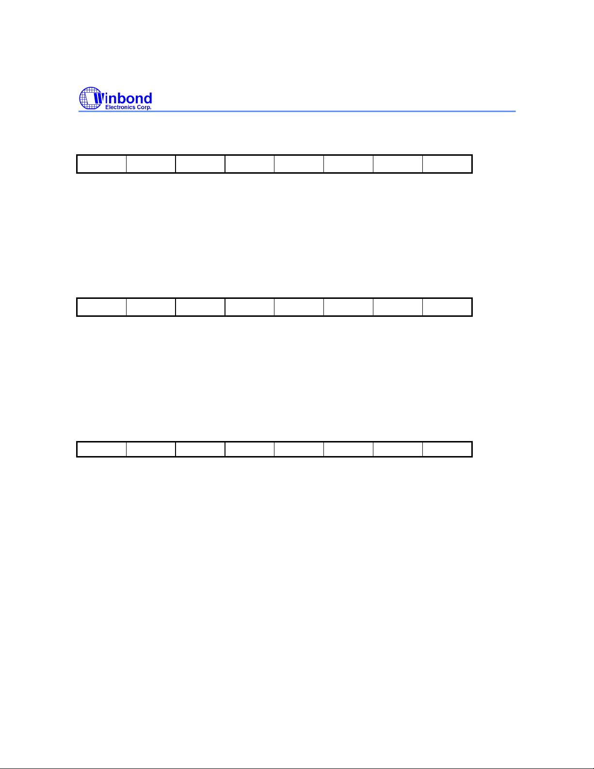
***IE - Interrupt Enable (A8H)
EA - ET2 ES ET1 EX1 ET0 EX0
EA: Lobal interrupt enable flag
ET2: Timer 2 overflow interrupt enable
ES: Serial port interrupt enable
EX1: External interrupt 1 enable
ET1: Timer 1 overflow interrupt enable
EX0: External interrupt 0 enable
***IP - Interrupt Priority (B8H)
- - PT2 PS PT1 PX1 PT0 PX0
PT2: Timer 2 interrupt priority high if set
PS: Serial port priority high if set
PT1: Timer 1 interrupt priority high if set
PX1: External interrupt 1 priority high if set
PT0: Timer 0 interrupt priority high if set
PX0: External interrupt 0 priority high if set
W78C54
***XICON - External Interrupt Control (C0H)
PX3 EX3 IE3 IT3 PX2 EX2 IE2 IT2
PX3: External interrupt 3 priority high if set
EX3: External interrupt 3 enable if set
IE3: If IT3 = 1, IE3 is set/cleared automatically by hardware when interrupt is detected/serviced
IT3: External interrupt 3 is falling-edge/low-level triggered when this bit is set/cleared by software
PX2: External interrupt 2 priority high if set
EX2: External interrupt 2 enable if set
IE2: If IT2 = 1, IE2 is set/cleared automatically by hardware when interrupt is detected/serviced
IT2: External interrupt 2 is falling-edge/low-level triggered when this bit is set/cleared by software
The W78C54 supports an eight-source and a four-priority-level interrupt architectures. Besides the
SFRs of IP and IE to control the six-source of the standard 8052 interrupt functions. There is an
another SFR (XICON) to control the extra two-source of the external interrrupt (INT2 and INT3). This
priority scheme is formed by combining IPH with IP to determine the priority of each interrupt. Except
the INT2 and INT3, they are not defined in IP SFR but in XICON.
Publication Release Date: December 1997
- 9 - Revision A2
Page 10
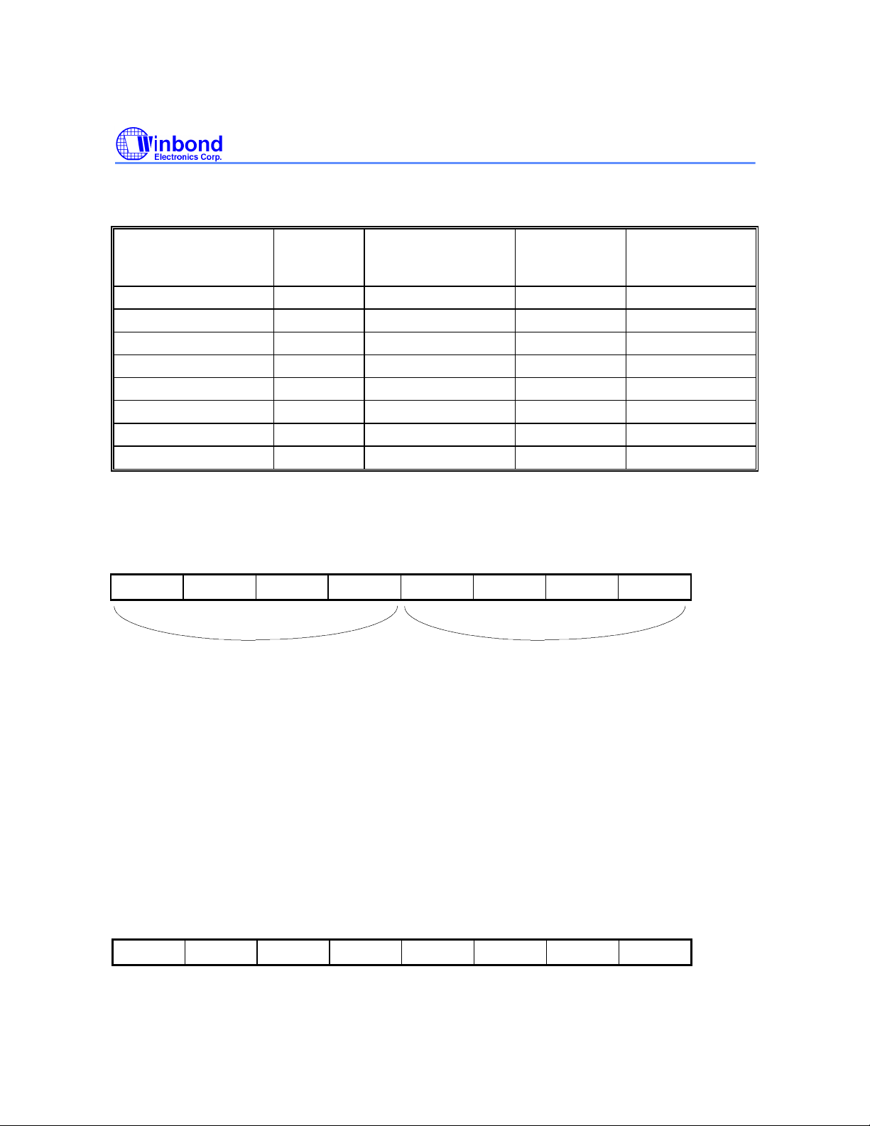
Following tables show the interrupt informations and priority definitions.
Eight-source interrupt informations:
W78C54
INTERRUPT
SOURCE
External Interrupt 0 03H 0 (highest) IE.0 TCON.IT0
Timer/Counter 0 0BH 1 IE.1 External Interrupt 1 13H 2 IE.2 TCON.IT1
Timer/Counter 1 1BH 3 IE.3 Serial Port 23H 4 IE.4 Timer/Counter 2 2BH 5 IE.5 External Interrupt 2 33H 6 XICON.EX2 XICON.IT2
External Interrupt 3 3BH 7 (lowest) XICON.EX3 XICON.IT3
VECTOR
ADDRESS
POLLING
SEQUENCE WITHIN
PRIORITY LEVEL
ENABLE
REQUIRED
SETTINGS
INTERRUPT
TYPE
EDGE/LEVEL
*Timer/Counter
***TL0, TH0, TL1, TH1, TL2, TH2, RCAP2L, RCAP2H
***TMOD - Timer 0, 1 mode (89H)
GATE C//T M1 M0 GATE C//T M1 M0
TIMER0
TIMER1
GATE: Gating control. When set, Timer/counter x is enabled only while INTx pin is high and TRx
control pin is set. When cleared, Timer x is enabled whenever the TRx conrol bit is set.
C//T: Timer or Counter Selector. Cleared for timer operation. Set for counter operation.
M1 M0: Operating Mode
0 0: 13-bit Timer/Counter.
0 1: 16-bit Timer/Counter.
1 0: 8-bit auto-reload Timer/Counter. THx holds a value which is to be reloaded into TLx
each time it overflows.
1 1: Timer 0: TL0 is an 8-bit timer/counter controlled by the standard Timer 0 control bits.
TH0 is an 8-bit timer only controlled by Timer 1 control bits.
Timer 1: Timer/counter 1 stopped.
***TCON - Timer 0, 1 Control (88H)
TF1 TR1 TF0 TR0 IE1 IT1 IE0 IT0
TF1: Timer 1 overflow flag. Set by hardware on timer/counter overflow. cleared by hardware when
processor vectors to interrupt routine.
- 10 -
Page 11
W78C54
TR1: Timer 1 run control bit. Set/cleared by software to turn timer/counter on or off.
TF0: Timer 0 overflow flag. Set by hardware on timer/counter overflow. Cleared by hardware when
processor vectors to interrupt routine.
TR0: Timer 0 run control bit. Set/cleared by software to turn timer/counter on or off.
IE1: Interrupt 1 edge flag. Set by hardware when external interrupt edge detected. Cleared when
interrupt processed.
IT1: Interrupt 1 type control bit. Set/cleared by software to specify falling edge/low level triggered
external interrupt.
IE0: Interrupt 0 edge flag. Set by hardware when external interrupt edge detected. Cleared when
interrupt processed.
IT0: Interrupt 0 type control bit. Set/cleared by software to specify falling edge/low level triggered
external interrupt.
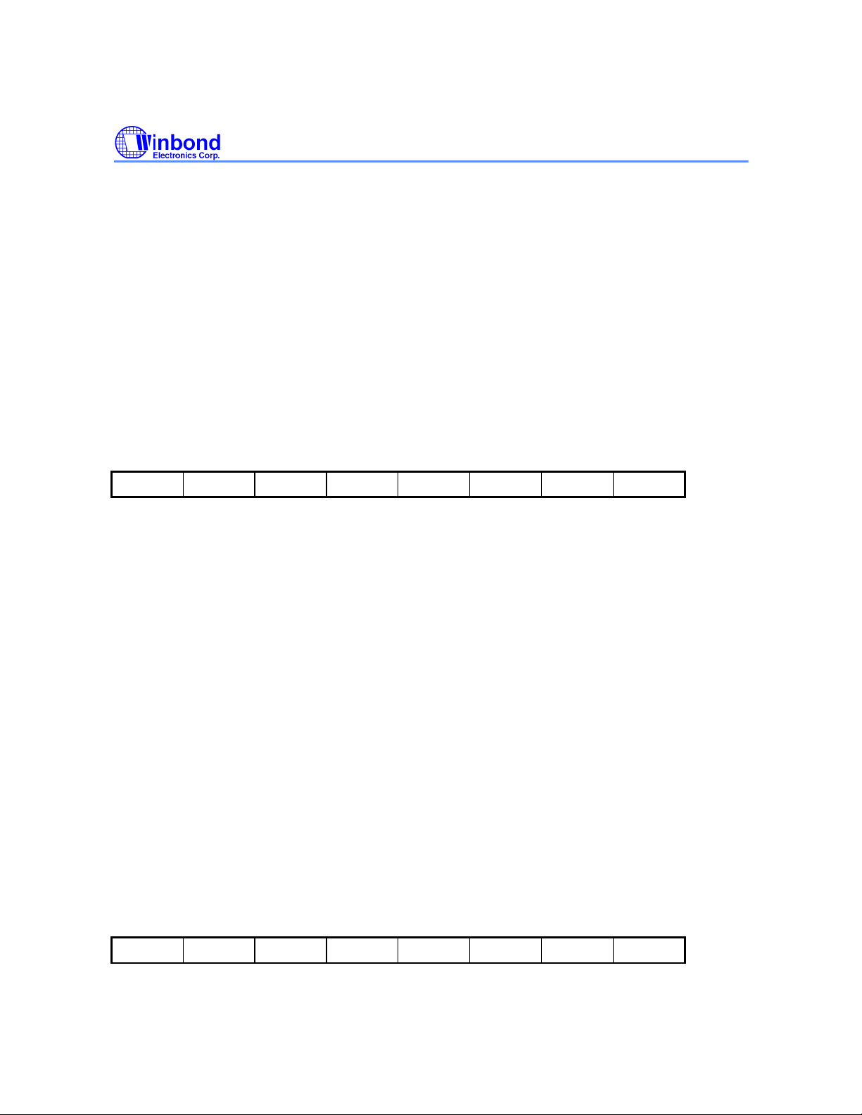
***T2CON - Timer 2 Control (C8H)
TF2 EXF2 RCLK TCLK EXEN2 TR2 C//T CP//RL2
TF2: Timer 2 overflow flag. Set by a Timer 2 overflow and must be cleared by software. TF2 will
not be set when RCLK = 1 or TCLK = 1.
EXF2: Timer2 external flag. Set when either a capture or reload is caused by a negative transition
on T2EX and EXEN2 = 1. When Timer 2 interrupt is enabled, EXF2 = 1 will cause the CPU
to vector to the Timer 2 interrupt routine. EXF2 must be cleared by software.
RCLK: Receive clock flag. RCLK = 1 causes the serial port to use Timer 2 overflow pulses for its
receive clock in mode 1 and 3. RCLK = 0 causes Timer 1 overflow to be used for the
receive clock.
TCLK: Transmit clock flag. TCLK = 1 causes the serial port to use Timer 2 overflow pulses for its
transmit clock in mode 1 and 3. TCLK = 0 causes Timer 1 overflow to be used for the
transmit clock.
EXEN2: Timer 2 external enable flag. EXEN2 = 1 allows a capture or reload to occur as a result of a
negative transition on T2EX if Timer 2 is not used to clock the serial port. EXEN2 = 0
causes Timer 2 to ignore events at T2EX.
TR2: TR2 = 1/0: turns on/off Timer 2.
C//T: Timer or Counter select. Set 1/0 for external event counter(falling edge triggered)/inter
timer.
CP//RL2:Capture/reload flag.
*Reduced EMI Mode
The AO bit in the AUXR register, when set, disables the ALE output.
***AUXR - Auxiliary Register (8EH)
- - - - - - - AO
AO: Turn off ALE output.
Publication Release Date: December 1997
- 11 - Revision A2
Page 12
W78C54
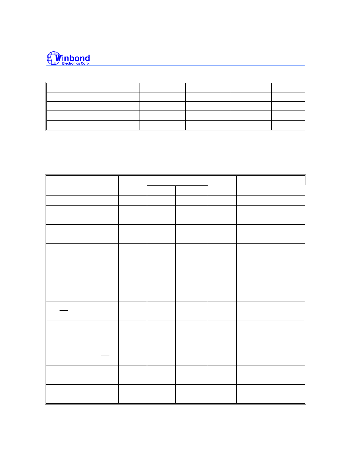
ABSOLUTE MAXIMUM RATINGS
PARAMETER SYMBOL MIN. MAX. UNIT
DC Power Supply VCC−VSS -0.3 +7.0 V
Input Voltage VIN VSS -0.3 VCC +0.3 V
Operating Temperature TA 0 70
Storage Temperature TST -55 +150
Note: Exposure to conditions beyond those listed under Absolute Maximum Ratings may adversely affect the life and reliability
of the device.
DC CHARACTERISTICS
(VDD−VSS = 5V ±10%, TA = 25°C, Fosc = 20 MHz, unless otherwise specified.)
PARAMETER SYM. SPECIFICATION UNIT TEST CONDITIONS
MIN. MAX.
Operating Voltage VDD 4.5 5.5 V
Operating Current IDD - 20 mA No load
VDD = 5.5V
°C
°C
Idle Current IIDLE - 6 mA Idle mode
VDD = 5.5V
Power Down Current IPWDN - 50
Input Current
P1, P2, P3, P4
Input Current
RST
Input Leakage Current
P0, EA
Logic 1 to 0 Transition
Current
P1, P2, P3, P4
Input Low Voltage
P0, P1, P2, P3, P4, EA
Input Low Voltage
RST
Input Low Voltage
XTAL1[*4]
IIN1 -50 +10
IIN2 -10 +300
ILK -10 +10
ITL [*4] -500 -200
VIL1 0 0.8 V VDD = 4.5V
VIL2 0 0.8 V VDD = 4.5V
VIL3 0 0.8 V VDD = 4.5V
µA
µA
µA
µA
µA
Power-down mode
VDD = 5.5V
VDD = 5.5V
VIN = 0V or VDD
VDD = 5.5V
0 < VIN < VDD
VDD = 5.5V
0V < VIN < VDD
VDD = 5.5V
VIN = 2.0V
- 12 -
Page 13
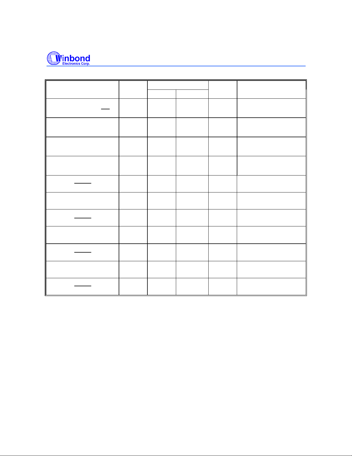
DC Characteristics, continued
PARAMETER SYM. SPECIFICATION UNIT TEST CONDITIONS
Input High Voltage
P0, P1, P2, P3, P4, EA
W78C54
MIN. MAX.
VIH1 2.4 VDD +0.2 V VDD = 5.5V
Input High Voltage
VIH2 3.5 VDD +0.2 V VDD = 5.5V
RST
Input High Voltage
VIH3 3.5 VDD +0.2 V VDD = 5.5V
XTAL1 [*4]
Output Low Voltage
P1, P2, P3, P4
Output Low Voltage
P0, ALE, PSEN [*3]
Sink Current
P1, P2, P3, P4
Sink Current
P0, ALE, PSEN
Output High Voltage
P1, P2, P3, P4
Output High Voltage
P0, ALE, PSEN [*3]
Source Current
P1, P2, P3, P4
Source Current
P0, ALE, PSEN
Notes:
*1. RST pin is a Schmitt trigger input. RST has internal pull-low resistors of about 30 KΩ.
*3. P0, ALE and /PSEN are tested in the external access mode.
*4. XTAL1 is a CMOS input.
*5. Pins of P1, P2, P3, P4 can source a transition current when they are being externally driven from 1 to 0. The transition
current reaches its maximum value when VIN approximates to 2V.
VOL1 - 0.45 V VDD = 4.5V
IOL = +2 mA
VOL2 - 0.45 V VDD = 4.5V
IOL = +4 mA
ISK1 4 8 mA VDD = 4.5V
Vs = 0.45V
ISK2 10 14 mA VDD = 4.5V
Vs = 0.45V
VOH1 2.4 - V VDD = 4.5V
IOH = -100 µA
VOH2 2.4 - V VDD = 4.5V
IOH = -400 µA
ISR1 -120 -180
µA
VDD = 4.5V
Vs = 2.4V
ISR2 -10 -14 mA VDD = 4.5V
Vs = 2.4V
AC CHARACTERISTICS
The AC specifications are a function of the particular process used to manufacture the part, the
ratings of the I/O buffers, the capacitive load, and the internal routing capacitance. Most of the
specifications can be expressed in terms of multiple input clock periods (TCP), and actual parts will
usually experience less than a ±20 nS variation. The numbers below represent the performance
expected from a 0.8 micron CMOS process when using 2 and 4 mA output buffers.
Publication Release Date: December 1997
- 13 - Revision A2
Page 14
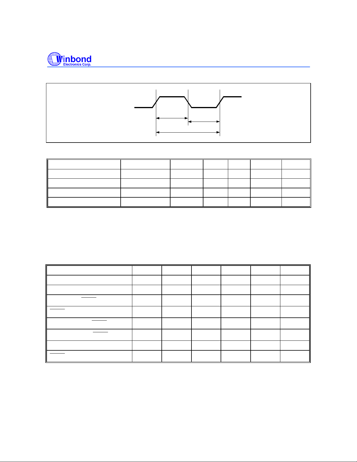
Clock Input Waveform
W78C54
XTAL1
T
Continued
CH
F
OP,
T
CL
T
CP
PARAMETER SYMBOL MIN. TYP. MAX. UNIT NOTES
Operating Speed FOP 0 - 40 MHz 1
Clock Period TCP 25 - - nS 2
Clock High TCH 10 - - nS 3
Clock Low TCL 10 - - nS 3
Notes:
1. The clock may be stopped indefinitely in either state.
2. The TCP specification is used as a reference in other specifications.
3. There are no duty cycle requirements on the XTAL1 input.
Program Fetch Cycle
External Program Memory Fetch Cycle (see Figure 6)
PARAMETER SYMBOL MIN. TYP. MAX. UINT NOTES
Address Valid to ALE Low TAAS
Address Hold After ALE Low TAAH
ALE Low to PSENLow
TAPL
1TCP -∆
1TCP -∆
1TCP -∆
- - nS
- - nS 1
1TCP
1TCP+∆
nS
PSEN Low to Data Valid
Data Hold After PSEN High
Data Float After PSEN High
ALE Pulse Width TALW
PSEN Pulse Width
Notes:
1. P00-P07, P20-P27 remain stable through entire memory cycle.
2. Memory access time is 3 Tcp.
3. Data has been latched internally prior to /PSEN going high.
4. ∆ is 20 ns (due to buffer driving delay and wire loading).
TPDA - - 2TCP nS 2
TPDH 0 - 1TCP nS 3
TPDZ 0 - 1TCP nS
2TCP -∆
TPSW
3TCP -∆
- 14 -
2TCP
3TCP
2TCP +∆
3TCP +∆
nS 4
nS 4
Page 15
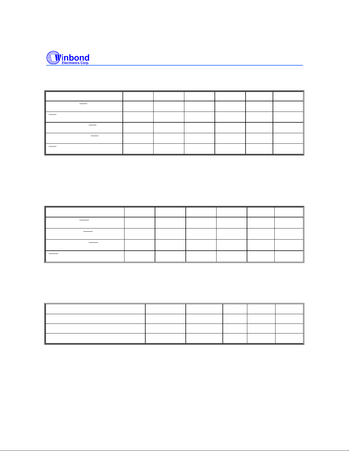
Data Read Cycle
RD
RD
WR
External Data Memory Read Cycle (see Figure 7)
PARAMETER SYMBOL MIN. TYP. MAX. UINT NOTES
ALE Low to RD Low
Low to Data Valid
Data hold After RD High
Data Float After RD High
Pulse Width
Notes:
1. Data Memory access time is 5 Tcp.
2. ∆ is 20 ns (due to buffer driving delay and wire loading.
TDAR
TDDA - - 4 Tcp nS 1
TDDH 0 - 2 Tcp nS
TDDZ 0 - 2 Tcp nS
TDRD
3 Tcp-∆
6 Tcp-∆
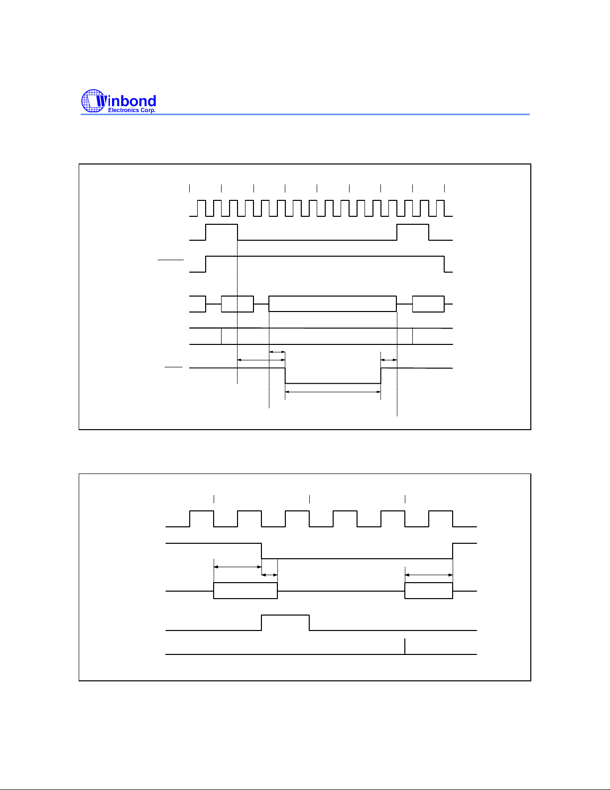
Data Write Cycle
External Data Memory Write Cycle (see Figure 8)
3 Tcp
6 Tcp
3 Tcp+∆
6 Tcp+∆
W78C54
nS 1, 2
nS 2
PARAMETER SYMBOL MIN. TYP. MAX. UINT NOTE
ALE Low to WR Low
Data Valid to WR Low
Data hold After WR High
Pulse Width
*Note: ∆ is 20 ns (due to buffer driving delay and wire loading)
TDAW
TDAD
TDWD
TDWR
3 Tcp-∆
1 Tcp-∆
1 Tcp-∆
6 Tcp-∆
3 Tcp
3 Tcp+∆
- - nS
- - nS
6 Tcp
6 Tcp+∆
nS *
nS *
Port Access Cycle
Port Access Cycle (see Figure 9)
PARAMETER SYMBOL MIN. TYP. MAX. UINT
Port Input Setup to ALE Low TPDS 1Tcp - - nS
Port Input Hold After ALE Low TPDH 0 - - nS
Port Output to ALE High TPDA
Note: Ports are read during S5P2, and output data becomes available at the end of S6P2. The timing data are referenced to
ALE, since it provides a convenient reference.
1Tcp-∆
- - nS
Publication Release Date: December 1997
- 15 - Revision A2
Page 16
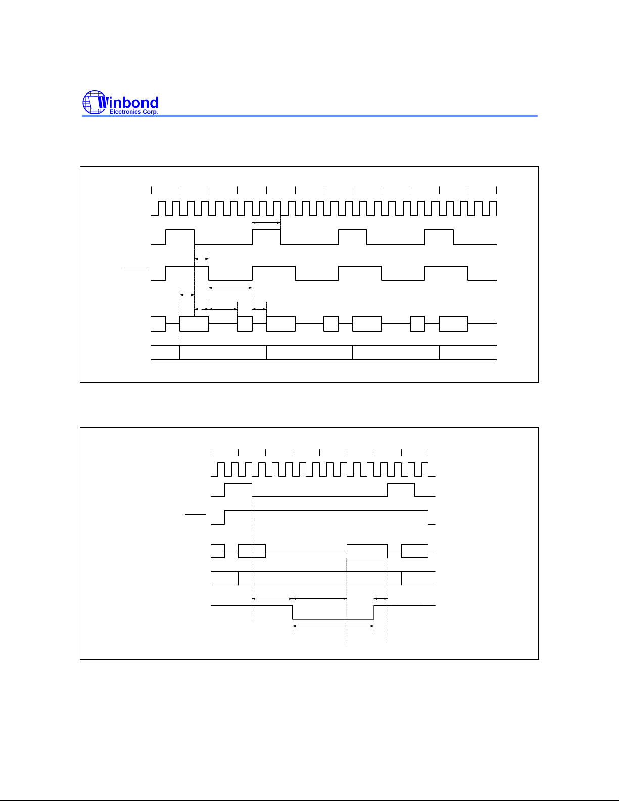
TIMING WAVEFORMS
Program Fetch Cycle
S1 S2 S3 S4 S5 S6 S1 S2 S3 S4 S5 S6
XTAL1
ALE
PSEN
Taas
Code
P0
PCL
out
Tapl
Taah
Tpsw
Tpda
Code
Talw
Tpdh,Tpdz
PCL
out
Code Code
PCL
out
W78C54
PCL
out
P2
Data Read Cycle
PCH out PCH out
Figure 6. External Program Memory Fetch Cycle
S4 S5 S6 S1 S2 S3 S4 S5
XTAL1
ALE
PSEN
DPL or
P0
RI out
P2
Tdar
/RD
DPH or P2 SFR out
Tdda
Tdrd
PCH out PCH out
Data
Tddh,Tddz
Figure7. External Data Memory Read Cycle
- 16 -
Page 17
Timing Waveforms, continued
Data Write Cycle
XTAL1
ALE
PSEN
W78C54
S4 S5 S6 S1 S2 S3 S4 S5
WR
Port Access Cycle
XTAL1
ALE
PORT
P0
P2
DPL or
RI out
Tdaw
Figure 8. External Data Memory Write Cycle
Tdad
Data
DPH or P2 SFR out
Tdwr
S5 S6 S1
Tpds
Tpdh
Data In
Tdwd
Tpda
Data Out
Input
Sample
Output
Clock
Figure 9. Port Access Cycle
Publication Release Date: December 1997
- 17 - Revision A2
Page 18
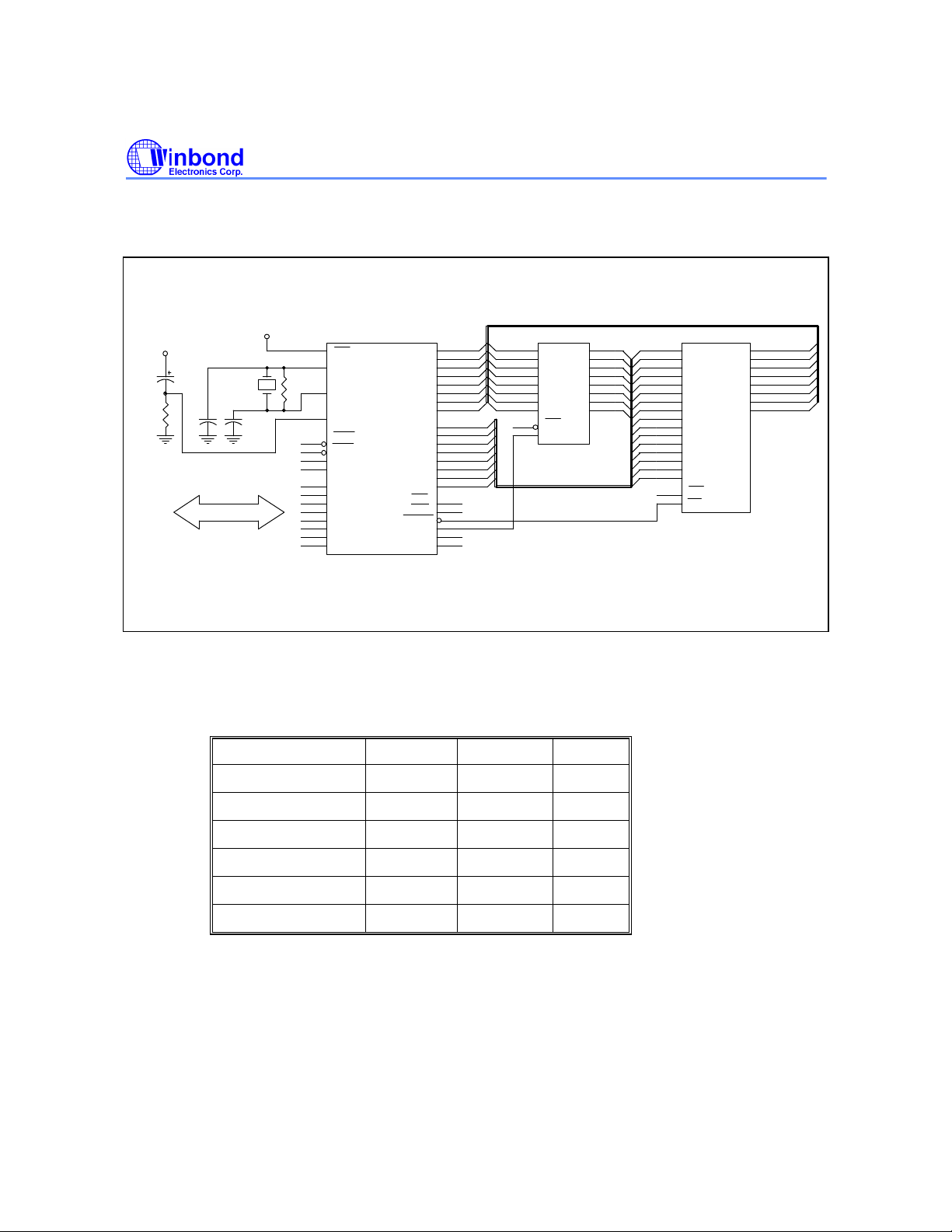
APPLICATION CIRCUIT
Expanded External Program Memory and Crystal
VCC
8.2K
VCC
10u
CRYSTAL
C1
C2
35
EA
21
X1
R
20
X2
10
RESET
INT0
14
15
INT1
16
T0
17
T1
P1.0
2
3
P1.1
4
P1.2
5
P1.3
6
P1.4
7
P1.5
8
P1.6
P1.7
9
W78C54
P0.0
P0.1
P0.2
P0.3
P0.4
P0.5
P0.6
P0.7
P2.0
P2.1
P2.2
P2.3
P2.4
P2.5
P2.6
P2.7
PSEN
ALE
TXD
RXD
RD
WR
AD0
AD1
AD2
AD3
AD4
AD5
AD6
AD7
A8
A9
A10
A11
A12
A13
A14
A15
AD0D0 3
AD1
AD2
AD3
AD4
AD5
AD6
AD7
GND
43
42
41
40
39
38
37
36
24
25
26
27
28
29
30
31
19
18
32
33
13
11
W78C54
AD0
A0
A0
2
Q0
4
D1
7
D2
8
D3
13
D4
14
D5
17
D6
18
D7
1
OC
11
G
74LS373
A1
5
Q1
A2
6
Q2
9
A3
Q3
12
A4
Q4
A5
15
Q5
A6
16
Q6
19
A7
Q7
A10
A11
A12
A13
A14
A15
GND
10
A0
A1
9
A1
A2
8
A2
A3
7
A3
A4
6
A4
A5
5
A5
A6
4
A6
A7
3
A7
25
A8
A8
24
A9
A9
21
A10
23
A11
2
A12
26
A13
27
A14
1
A15
20
CE
22
OE
27512
11
O0
12
O1
O2
O3
O4
O5
O6
O7
AD1
13
AD2
15
AD3
16
AD4
17
AD5
18
AD6
19
AD7
Figure A
Table 1 Shows the typical values of off-chip components to configure the on-chip oscillator.
Table 1. Off-chip components list
CRYSTAL FREQ. C1 C2 R
12 MHz 30 pF 30 pF 16 MHz 30 pF 30 pF 20 MHz 15 pF 15 pF 24 MHz 15 pF 15 pF 33 MHz 10 pF 10 pF
40MHz 5 pF 5 pF
Notes:
1. Refer to Figure 10 for C1, C2 and R.
2. It is recommended that an oscillator be used as external clock source when operating freq. is above 35MHz. Apply the
external clock signal to XTAL1, and leave XTAL2 float, as shown in Figure 10.
6.8 KΩ
4.3 KΩ
- 18 -
Page 19
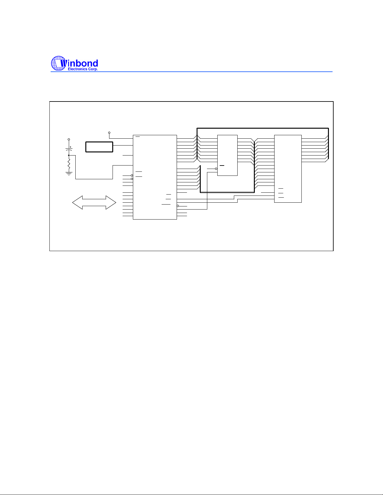
Application Circuit, continued
Expanded External Data Memory and Oscillator
VCC
8.2K
VCC
10u
OSCILLATOR
35
21
20
10
14
15
16
17
EA
X1
X2
RESET
INT0
INT1
T0
T1
2
P1.0
3
P1.1
4
P1.2
5
P1.3
6
P1.4
7
P1.5
8
P1.6
9
P1.7
W78C54
P0.0
P0.1
P0.2
P0.3
P0.4
P0.5
P0.6
P0.7
P2.0
P2.1
P2.2
P2.3
P2.4
P2.5
P2.6
P2.7
PSEN
TXD
RXD
WR
ALE
AD1
42
AD2
41
AD3
40
AD4
39
AD5
38
AD6
37
36
AD7
A8
24
25
A9
26
A10
27
A11
28
A12
A13
29
30
A14
31
RD
19
18
32
33
13
11
AD0
43
AD0
AD1
AD2
AD3
AD4
AD5
AD6
AD7
GND
W78C54
3
D0 Q0
4
D1 Q1
7
D2 Q2
8
D3 Q3
13
D4 Q4
14
D5 Q5
17
D6
18
D7
1
OC
G 11
74LS373
2
5
6
9
12
15
16
Q6
19
Q7
A0 10
A0
A1
A1
A2
A2
A3
A3
A4
A4
A5
A5
A6
A6
A7
A7
A8
A9
A10
A11
A12
A13
A14
GND
A0
A1
A2
A3
A4
A5
A6
A7
A8
A9
A10
A11
A12
A13
A14
CE
OE
WR
20256
D0
D1
D2
D3
D4
D5
D6
D7
9
8
7
6
5
4
3
25
24
21
23
2
26
1
20
22
27
AD0
11
AD1
12
AD2
13
AD3
15
AD4
16
AD5
17
AD6
18
AD7
19
Figure B
Publication Release Date: December 1997
- 19 - Revision A2
Page 20
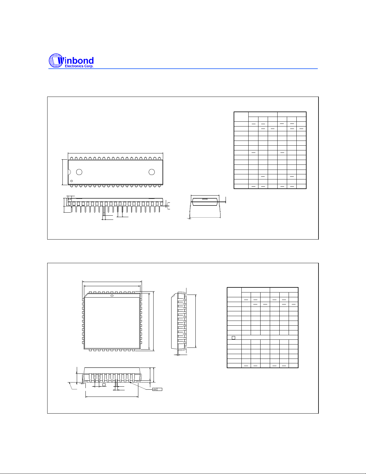
PACKAGE DIMENSIONS
40-pin DIP
40
1
E
S
A
2
A
L
D
B
B
1
W78C54
Dimension in inch Dimension in mm
Symbol
A
A
A
B
B
c
21
D
E
E
e
L
a
e
201
Base Plane
1
A
Seating Plane
e
1
E
e A
a
S
Notes:
1. Dimension D Max. & S include mold flash or
tie bar burrs.
c
2. Dimension E1 does not include interlead flash.
3. Dimension D & E1 include mold mismatch and
are determined at the mold parting line.
4. Dimension B1 does not include dambar
protrusion/intrusion.
5. Controlling dimension: Inches.
6. General appearance spec. should be based on
final visual inspection spec.
Nom.
Min.
0.010
1
0.155
0.150
2
0.016
0.018
0.050 1.27
1
0.008
0.010
2.055 2.070 52.20 52.58
0.6000.590
0.540
1
1
0.120
0.130
0 15
0.6500.630 16.00 16.51
A
Min.
0.254
3.81
0.406
0.203
14.986
13.72
2.286 2.54 2.7940.090 0.100
3.048
Nom.
3.937
0.457
0.254
15.24
13.84
3.302
4.064
0.559
1.3721.2190.0540.048
0.356
15.494
17.01
Max. Max.
0.210
0.160
0.022
0.014
0.610
0.5500.545
0.110
0.140
0.670
0.090
.
5.334
13.97
3.556
2.286
150
44-pin PLCC
7
17
L
θ
Seating Plane
6 1
e
H
D
D
44 40
G
D
Dimension in inch Dimension in mm
Symbol
39
H
E
E
29
2818
A
2
A
b
b
1
A
1
y
G
E
c
A
A
A
b1
b
c
D
E
e
G
G
H
HE
L
y
Notes:
1. Dimension D & E do not include interlead
flash.
2. Dimension b1 does not include dambar
protrusion/intrusion.
3. Controlling dimension: Inches
4. General appearance spec. should be based
on final visual inspection spec.
Nom.
Min.
0.020
1
0.145
2
0.026
0.016
0.008
0.648
0.590
D
0.590
E
0.680
D
0.680
0.090
Max. Max.
0.185
0.150
0.155
0.028
0.032
0.022
0.018
0.010
0.014
0.653
0.658
0.6580.6530.648
0.050 BSC
0.610
0.630
0.6300.610
0.690
0.700
0.700
0.690
0.100
0.110
0.004
Min.
0.508
3.683
0.66
0.406
0.203
16.46
14.99
17.27
17.27
2.296
1.27
Nom.
3.81
0.711
0.457
0.254
16.59
15.49
15.4914.99
17.53
2.54
BSC
4.699
3.937
0.813
0.559
0.356
16.71
16.7116.5916.46
16.00
16.00
17.78
17.7817.53
2.794
0.10
- 20 -
Page 21
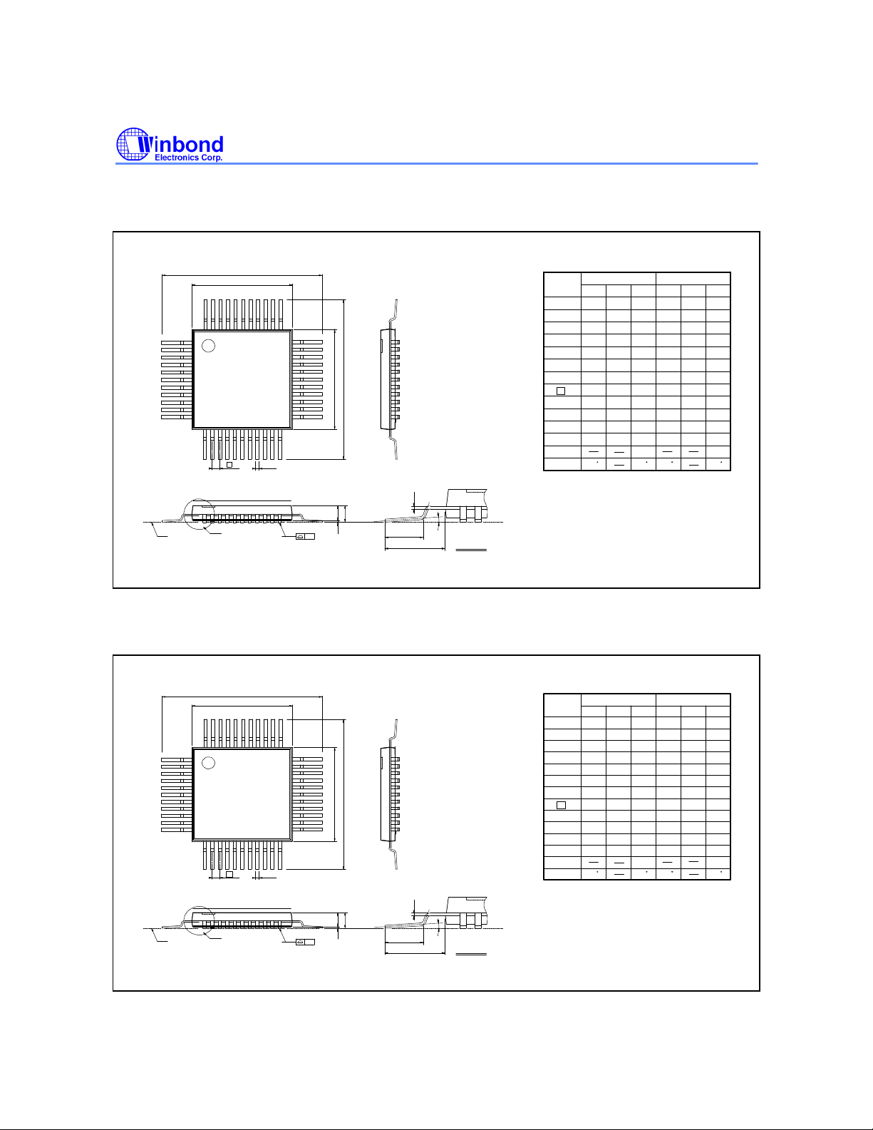
Package Dimensions, continued
1
2
44-pin QFP
H
D
D
44
1
11
12
e
Seating Plane
See Detail F
W78C54
Dimension in inch
34
33
Symbol
A
A
A
b
1
2
c
D
E
EH
E
e
D
H
E
H
L
1
L
22
b
c
A
A
2
A
1
y
θ
L
L 1
Detail F
y
θ
Notes:
1. Dimension D & E do not include interlead
flash.
2. Dimension b does not include dambar
protrusion/intrusion.
3. Controlling dimension: Millimeter
4. General appearance spec. should be based
on final visual inspection spec.
Nom.
Min.
--- ---
0.002
0.01 0.02 0.25
0.081
0.075
0.01
0.014
0.006 0.152
0.394
0.390
0.390
0.025
0.031
0.510 13.45
0.520
0.520
0.510
0.025
0.031
0.063
0.051 0.075 1.295
0
Dimension in mm
Max. Max.
---
0.087
0.018
0.0100.004
0.398
0.3980.394
0.036
0.530
0.530
0.037
0.003
Nom.
Min.
--- ---
0.05
1.90
0.25
9.9
9.9
0.635
12.95
12.95
0.65
7
0
2.05
0.35
10.00
10.00
0.80
13.2
---
0.5
2.20
0.45
0.2540.101
10.1
10.1
0.952
13.4513.2
0.8
0.95
1.6
1.905
0.08
7
44-pin TQFP
44
1
11
12
Seating Plane
H
D
D
e
See Detail F
Dimension in inch Dimension in mm
Symbol
34
33
E
EH
22
b
Notes:
c
A
A
A
1
y
θ
L
L
Detail F
Min. Nom. Max. Max.Nom.Min.
A
1
A
2
A
b
c
D
E
e
D
H
E
H
L
1
L
y
θ
1. Dimension D & E do not include interlead
flash.
2. Dimension b does not include dambar
protrusion/intrusion.
3. Controlling dimension: Millimeter
4. General appearance spec. should be based
on final visual inspection spec.
--- ---
0.002
0.004 0.006 0.10
0.037
0.039
0.0039
0.013
---
0.394
0.390
0.390
0.025
0.031
0.468 12.10
0.472
0.472
0.468
0.018
0.024
0.039
---
0
0.047
0.041
0.015
0.0080.004
0.398
0.3980.394
0.036
0.476
0.476
0.030
0.003
---
7
--- ---
0.05
0.95
0.22
9.9
9.9
0.635
11.90
11.90
0.45
--- ---
0
1.00
0.32
10.00
10.00
12.00
1.20
0.15
1.05
0.38
0.2000.090
---
10.1
10.1
0.952
0.80
12.1012.00
0.60
0.75
1.00
0.08
7
Publication Release Date: December 1997
- 21 - Revision A2
Page 22

W78C54
Note: All data and specifications are subject to change without notice.
Headquarters
No. 4, Creation Rd. III,
Science-Based Industrial Park,
Hsinchu, Taiwan
TEL: 886-3-5770066
FAX: 886-3-5792697
http://www.winbond.com.tw/
Voice & Fax-on-demand: 886-2-27197006
Taipei Office
11F, No. 115, Sec. 3, Min-Sheng East Rd.,
Taipei, Taiwan
TEL: 886-2-27190505
FAX: 886-2-27197502
Winbond Electronics (H.K.) Ltd.
Rm. 803, World Trade Square, Tower II,
123 Hoi Bun Rd., Kwun Tong,
Kowloon, Hong Kong
TEL: 852-27513100
FAX: 852-27552064
- 22 -
Winbond Electronics North America Corp.
Winbond Memory Lab.
Winbond Microelectronics Corp.
Winbond Systems Lab.
2727 N. First Street, San Jose,
CA 95134, U.S.A.
TEL: 408-9436666
FAX: 408-5441798
 Loading...