

Datasheet VV6404C001, VV6404C001-B2, VV6301B001, VV5404C001, STV6404E-001 Datasheet (Vision)
...Page 1
®
Mono and Colour Digital Video CMOS Image Sensors
CD5404-6404F-A
1/54
VV5404 & VV6404
DESCRIPTION
VV5404 and VV6404 are highly integrated CMOS VLSI
sensors which enables high standards of performance and
image quality at a very cost-effective price point. The 356 x
292 monochrome device offers one of the simplest routes
currently available to design-in of imaging applications, while
the colour device is ideal for low cos t PC camera applicati ons.
Both devices incorporat e a comprehens ive range of on-boar d
controls eliminating th e need for addition al support chips . Onchip A/D conversion provides 8 bit digital output and the
device set up i s fully automati c via th e built-in automati c black
level calibration algorithm.
Exposure and gain set tings are programma ble an d o peration
is controlled via a serial interface.
This sensors offer v ariabl e fram e rates of up to 30 fram es p er
second and a 4 wire digital video bus. The digital interface
also provides a t ri-stateable data qualification clock and fram e
synchronisation si gnal.
Hand-held products, in applications such as PDAs, bar code
scanning or autom atic me ter reading , will bene fit from th e low
power requirements and from the inbuilt sleep and power
down modes.
The price and performance standards introduced with the
VV5404 and VV6404 enable use of an imaging solution
where previously it may not have been practicable on cost
grounds.
BLOCK DIAGRAM
FEATURES
• CIF Format mono or colour pixel array
• Up to 30 frames per second operation
• On-chip 8 bit analogue to digital converter
• Low power consumption
• Up to 356 x 292 pixel image size
• Automatic exposure and gain control
• Serial interface control
• Programmable exposure and gain values
• Automatic black level calibration
• 4-wire digital video bus
• Evaluation kit available
APPLICATIONS
• PC Cameras
• Biometrics
• Inspection Systems
SPECIFICATIONS
Important:
1. A colour co-processor is required to convert the VV6404 sensor’s video
data stream of raw colourised pixel data into either a CIF or QCIF format RGB or YUV colour image.
2. VV5404 and VV6404 do NOT have any form of automatic exposure
control. This must be performed externally.
SAMPLE & HOLD
HORIZONTAL SHIFT
PHOTO DIODE
ANALOG
VOLTAGE
REFS.
SDA
SCL
D[3:0]
VERTICAL
SHIFT
REGISTER
CLKO
8-bit
ADC
ARRAY
REGISTER
SERIAL
INTER-
FACE
OUTPUT
FORMAT
GAIN
IMAGE
FORMAT
BLACK
CALIBRATION
EXPOSURE
REGISTERS
STAGE
OEB
FST
QCK
SIN
CLKI
Pixel resolution
356 x 292 (CIF)
Array size
4.272mm x 3.212mm
Pixel size
12.0 µm x 1 1.0 µm
Min. illumination
0.1 lux
Exposure control
Automatic (to 25000:1)
Gain control
Automatic (to +20dB)
Signal/Noise ratio
46dB
Supply voltage
5.0v DC
+/−
5%
Supply curren t
<75mA
Operating
temperature
(ambient)
0
o
C - 40oC
(for extended temp. info please contact STMicroelectronics)
Package type
48LCC
Page 2

VV5404 & VV6404
CD5404-6404F-A
2/54
Table of Contents
1. Introduction. . . . . . . . . . . . . . . . . . . . . . . . . . . . . . . . . . . . . . . . . . . . . . . . . . . . . . . . . . .4
2. Operating Modes . . . . . . . . . . . . . . . . . . . . . . . . . . . . . . . . . . . . . . . . . . . . . . . . . . . . . .6
2.1 Image Read-out Options. . . . . . . . . . . . . . . . . . . . . . . . . . . . . . . . . . . . . . . . . . . . . . . . .6
2.2 Frame Rate Options. . . . . . . . . . . . . . . . . . . . . . . . . . . . . . . . . . . . . . . . . . . . . . . . . . . .6
3. Exposure Control . . . . . . . . . . . . . . . . . . . . . . . . . . . . . . . . . . . . . . . . . . . . . . . . . . . . . .8
4. Digital Video Interface Format. . . . . . . . . . . . . . . . . . . . . . . . . . . . . . . . . . . . . . . . . . . .9
4.1 General description. . . . . . . . . . . . . . . . . . . . . . . . . . . . . . . . . . . . . . . . . . . . . . . . . . . . .9
4.2 Embedded control data. . . . . . . . . . . . . . . . . . . . . . . . . . . . . . . . . . . . . . . . . . . . . . . . . .9
4.2.1 The combined escape and sync character . . . . . . . . . . . . . . . . . . . . . . . . . . . . . . . . .9
4.2.2 The command word. . . . . . . . . . . . . . . . . . . . . . . . . . . . . . . . . . . . . . . . . . . . . . . . . . .9
4.2.3 Supplementary Data. . . . . . . . . . . . . . . . . . . . . . . . . . . . . . . . . . . . . . . . . . . . . . . . .13
4.3 Video timing reference and status/configuration data. . . . . . . . . . . . . . . . . . . . . . . . . .13
4.3.1 Blank lines. . . . . . . . . . . . . . . . . . . . . . . . . . . . . . . . . . . . . . . . . . . . . . . . . . . . . . . . .14
4.3.2 Bla ck line timing. . . . . . . . . . . . . . . . . . . . . . . . . . . . . . . . . . . . . . . . . . . . . . . . . . . . .14
4.3.3 Valid video line timing . . . . . . . . . . . . . . . . . . . . . . . . . . . . . . . . . . . . . . . . . . . . . . . .14
4.3.4 Start of frame line timing . . . . . . . . . . . . . . . . . . . . . . . . . . . . . . . . . . . . . . . . . . . . . .14
4.3.5 End of frame line timing. . . . . . . . . . . . . . . . . . . . . . . . . . . . . . . . . . . . . . . . . . . . . . .14
4.4 Detection of sensor using data bus state . . . . . . . . . . . . . . . . . . . . . . . . . . . . . . . . . . .14
4.5 Resetting the Sensor Via the Serial Interface. . . . . . . . . . . . . . . . . . . . . . . . . . . . . . . . 14
4.6 Power-up, Low-power and Sleep modes . . . . . . . . . . . . . . . . . . . . . . . . . . . . . . . . . . .14
4.6.1 Power-Up/Down (Figure 12) . . . . . . . . . . . . . . . . . . . . . . . . . . . . . . . . . . . . . . . . . . .1 8
4.6.2 Low-Power Mode (Figure 10) . . . . . . . . . . . . . . . . . . . . . . . . . . . . . . . . . . . . . . . . . .18
4.6.3 Sleep Mode (Figure 11). . . . . . . . . . . . . . . . . . . . . . . . . . . . . . . . . . . . . . . . . . . . . . .18
4.6.4 Application of the system clock during sensor low-power modes . . . . . . . . . . . . . . . 22
4.7 Qualification of Output Data . . . . . . . . . . . . . . . . . . . . . . . . . . . . . . . . . . . . . . . . . . . . .22
4.7.1 Using the External Clock signal applied to CKI . . . . . . . . . . . . . . . . . . . . . . . . . . . . . 22
4.7.2 Data Qualification Clock, QCK. . . . . . . . . . . . . . . . . . . . . . . . . . . . . . . . . . . . . . . . . .22
4.7.3 Frame Start Signal, FST . . . . . . . . . . . . . . . . . . . . . . . . . . . . . . . . . . . . . . . . . . . . . .22
5. Serial Control Bus . . . . . . . . . . . . . . . . . . . . . . . . . . . . . . . . . . . . . . . . . . . . . . . . . . . .2 7
5.1 General Description . . . . . . . . . . . . . . . . . . . . . . . . . . . . . . . . . . . . . . . . . . . . . . . . . . .27
5.2 Serial Communication Protocol . . . . . . . . . . . . . . . . . . . . . . . . . . . . . . . . . . . . . . . . . .27
5.3 Data Format. . . . . . . . . . . . . . . . . . . . . . . . . . . . . . . . . . . . . . . . . . . . . . . . . . . . . . . . .27
5.4 Message Interpretation. . . . . . . . . . . . . . . . . . . . . . . . . . . . . . . . . . . . . . . . . . . . . . . . .28
5.5 The Programmers Model . . . . . . . . . . . . . . . . . . . . . . . . . . . . . . . . . . . . . . . . . . . . . . .29
5.5.1 DeviceH [000_00002] and DeviceL [000_ 00012]. . . . . . . . . . . . . . . . . . . . . . . . . . .31
5.5.2 Status0 [000_00102] . . . . . . . . . . . . . . . . . . . . . . . . . . . . . . . . . . . . . . . . . . . . . . . . .31
5.5.3 Line_count_H [000_00112] & Line_count_L [000_01002]. . . . . . . . . . . . . . . . . . . . .31
5.5.4 Setup0 [001_00002] . . . . . . . . . . . . . . . . . . . . . . . . . . . . . . . . . . . . . . . . . . . . . . . . .32
5.5.5 Setup1 [001_00012] . . . . . . . . . . . . . . . . . . . . . . . . . . . . . . . . . . . . . . . . . . . . . . . . .32
5.5.6 Setup2 [001_00102] . . . . . . . . . . . . . . . . . . . . . . . . . . . . . . . . . . . . . . . . . . . . . . . . .33
5.5.7 Setup4 [001_01002] . . . . . . . . . . . . . . . . . . . . . . . . . . . . . . . . . . . . . . . . . . . . . . . . .33
5.5.8 Setup5 [001_01012] . . . . . . . . . . . . . . . . . . . . . . . . . . . . . . . . . . . . . . . . . . . . . . . . .34
5.5.9 Expos ure Control Reg isters [010_00002] - [010_10012] . . . . . . . . . . . . . . . . . . . . . . 35
5.5.10 ADC Setup Register AS0 [111_01112] . . . . . . . . . . . . . . . . . . . . . . . . . . . . . . . . . .37
5.6 Types of messages. . . . . . . . . . . . . . . . . . . . . . . . . . . . . . . . . . . . . . . . . . . . . . . . . . . .38
5.6.1 Single location, single data write. . . . . . . . . . . . . . . . . . . . . . . . . . . . . . . . . . . . . . . .38
Page 3

VV5404 & VV6404
CD5404-6404F-A
3/54
5.6.2 Single location, single data read.. . . . . . . . . . . . . . . . . . . . . . . . . . . . . . . . . . . . . . . .38
5.6.3 No data write followed by same location read. . . . . . . . . . . . . . . . . . . . . . . . . . . . . .38
5.6.4 Same location multiple data write.. . . . . . . . . . . . . . . . . . . . . . . . . . . . . . . . . . . . . . .39
5.6.5 Same location multiple data read . . . . . . . . . . . . . . . . . . . . . . . . . . . . . . . . . . . . . . .39
5.6.6 Multiple location write . . . . . . . . . . . . . . . . . . . . . . . . . . . . . . . . . . . . . . . . . . . . . . . .40
5.6.7 Multiple location read. . . . . . . . . . . . . . . . . . . . . . . . . . . . . . . . . . . . . . . . . . . . . . . . .40
5.7 Serial Interface Timing . . . . . . . . . . . . . . . . . . . . . . . . . . . . . . . . . . . . . . . . . . . . . . . . .4 1
6. Clock Signal . . . . . . . . . . . . . . . . . . . . . . . . . . . . . . . . . . . . . . . . . . . . . . . . . . . . . . . . .42
6.8 Synchronising 2 or More Cameras. . . . . . . . . . . . . . . . . . . . . . . . . . . . . . . . . . . . . . . .43
7. Detailed specifications. . . . . . . . . . . . . . . . . . . . . . . . . . . . . . . . . . . . . . . . . . . . . . . . .45
7.1 General. . . . . . . . . . . . . . . . . . . . . . . . . . . . . . . . . . . . . . . . . . . . . . . . . . . . . . . . . . . . .45
7.2 DC characteristics. . . . . . . . . . . . . . . . . . . . . . . . . . . . . . . . . . . . . . . . . . . . . . . . . . . . .45
8. Physical. . . . . . . . . . . . . . . . . . . . . . . . . . . . . . . . . . . . . . . . . . . . . . . . . . . . . . . . . . . . .46
8.1 Pinout Diagram. . . . . . . . . . . . . . . . . . . . . . . . . . . . . . . . . . . . . . . . . . . . . . . . . . . . . . .46
8.2 Signal Names. . . . . . . . . . . . . . . . . . . . . . . . . . . . . . . . . . . . . . . . . . . . . . . . . . . . . . . .47
8.3 48LCC Mechanical Dimensions . . . . . . . . . . . . . . . . . . . . . . . . . . . . . . . . . . . . . . . . . .49
8.4 VV6404 Sensor Support Circuit Schematic Diagram. . . . . . . . . . . . . . . . . . . . . . . . . .50
8.5 Sensor Support Circuit Component List . . . . . . . . . . . . . . . . . . . . . . . . . . . . . . . . . . .50
9. Ordering Information . . . . . . . . . . . . . . . . . . . . . . . . . . . . . . . . . . . . . . . . . . . . . . . . . .52
Page 4
VV5404 & VV6404
CD5404-6404F-A
4/54
1. Introduction
VV5404 and VV6404 are CIF format CMOS image sensors capable of outputing digital pixel data at frame rates, of
upto 30 frames per second. The VV5404 is a monochrome part, while the VV6404 has a colour filter applied over the
sensor array.
Important:
The VV6404 sensor’s video data stream only contains raw colourised pixel data. A colour co-processor
is required to generate for example either a CIF or a QCIF format YUV colour image.
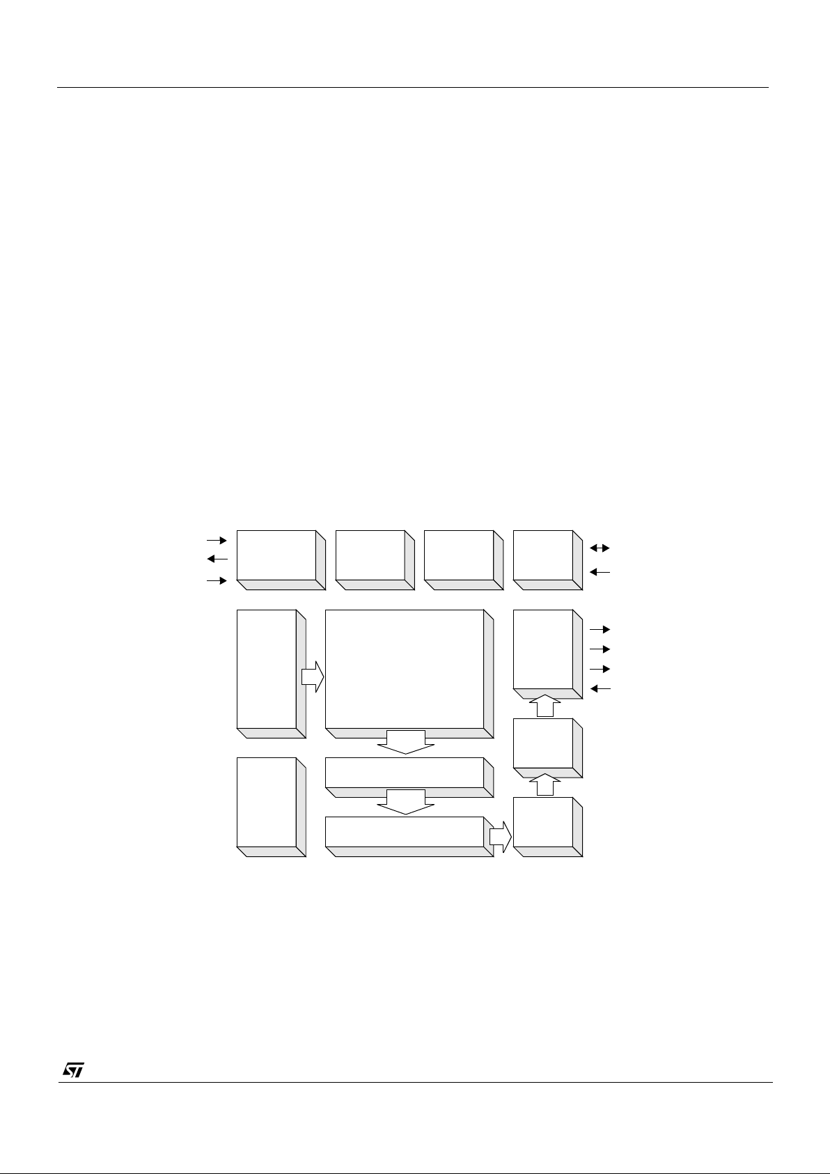
The 356 x 292 pi xel senso rs have an on-chip 8-bi t analogue to digital con verter (F igure 1). T he sensors offer very
flexible digital interface, the main components of which are listed below:
1. A tri-stateable 4-wire data bus (D[3:0]) for sending both video data and embedded timing references.
2. A data qualification clock, QCK, which can be programmable via the serial interface to behave in a number of
different ways (Tri-stateable).
3. A frame start signal, FST (Tri-stateable).
4. A 2-wire serial interface (SDA,SCL) for controlling and setting up the device.
5. The ability to synchronise the operation of multiple cameras - synchronisation input, SIN.
An 8-bit pixel value is transmitted across the 4 wire tri-stateable databus as series pair of 4-bit nibbles, most significant
nibble first. Along within the pixel data, codes representing the start and end frames and the start and end of lines are
embedded within the video data strea m to allow the video processor to synchronise with video dat a the camera
module is generating. Section 4. defines the format for the output video datastream.
To complemen t the embedded control sequences a data qualification clock, QCK, and a frame start signal are also
available. QCK can be set-up to either be:
1. Disabled
2. Free-running.
3. Qualify onl y the con tr ol se quen ce s and the pixel data.
4. Qualify the pixel data only
There is also the choice of two different QCK frequencies, where one is twice the frequency of the other.
SAMPLE & HOLD
HORIZONTAL SHIFT
PHOTO DIODE
ANALOG
VOLTAGE
REFS.
SDA
SCL
D[3:0]
VERTICAL
SHIFT
REGISTER
CLKO
8-bit
ADC
ARRAY
REGISTER
SERIAL
INTER-
FACE
Figure 1 : Block Diagram of VV5404 and VV6404 Image Sensors
OUTPUT
FORMAT
GAIN
IMAGE
FORMAT
BLACK
CALIBRATION
EXPOSURE
REGISTERS
STAGE
OEB
FST
QCK
SIN
CLKI
Page 5
VV5404 & VV6404
CD5404-6404F-A
5/54
1. Fast QCK: the falling edge of the clock qualifies the nibble data irrespective of whether it is the most or the least
significant nibble.
2. Slow QCK: the rising edge of the clock qualifies the most significant nibbles while the falling edge of the clock
qualifies the leas t sign ificant nibbles.
The FST can be enabled/disabled via the serial interface.
OEB tri-states all 4 databus lines, D[3:0], the qualification clock, QCK and the frame start signal, FST.
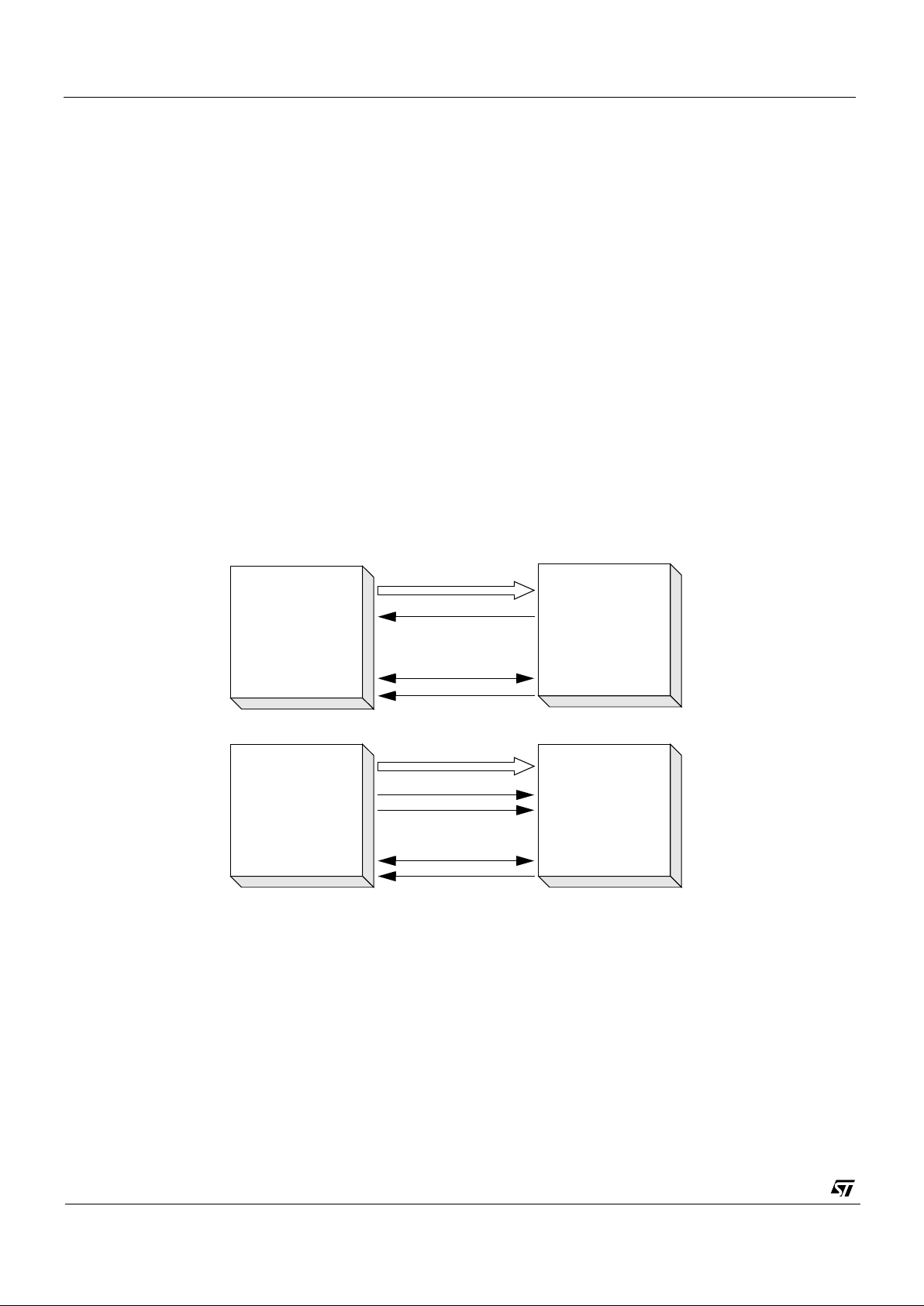
There are 3 main ways of interfacing to the VV5404 or VV6404 sensor based on the above signals:
1. The processor capturing the data (or colour co-processor for VV6404) supplies the sensor clock, CKI, and uses
the embedded control sequences to synchronise with the frame and line level timings. Thus the processor and
sensor are running off derivatives of the same fundamental clock (4 fsc - 14.31818 MHz). To allow the receiver
to determ ine the bes t sam pli ng pos ition of the video data, durin g its power-up sequen ce the sensor outputs a
101010... sequence on each of its databus lines for the video processor to lock on to.
2. The video processor uses a free-running QCK supplied by the sensor to sample the incoming video data
stream. The embedded control sequences are used to synchronise the frame and line level timings. A crystal is
used to generate the clock for the sensor.
3. The video processor uses FST and the data only mode for QCK to synchronise to the incoming video data. Primarily intended for interfacing to frame grabbers.
The 2-wire serial interface provides complete control over how the sensor is setup and run. Exposure and gain values
are programmed via this interface. Section 5. defines the communications protocol and the register map of all the
locations which can be accessed via the serial interface.
Using the first two interface options outlined above it is possible to control the sensor and receive video data via a 9wire cable between the sensor and the video processor/colour-processor.
1. A 4-wire data bus (D[3:0]) for sending both vide o data and embedded ti m ing r eferences.
2. A 2-wire serial interface (SDA,SCL).
3. The clock for the sensor or QCK from the sensor.
4. VCC and GND power lines.
The various image read-out and frame rate options are detailed in Sections 2 and 3 respectively.
Figure 2 : Interfacing Options
SDA
SCL
D[3:0]
CLKI
Sensor
Colour
Co-processor
(processor)
SDA
SCL
D[3:0]
QCK
Sensor
Colour
Co-processor
(processor)
FST
Page 6
VV5404 & VV6404
CD5404-6404F-A
6/54
2. Operating Modes
2.1 Image Read-out Options
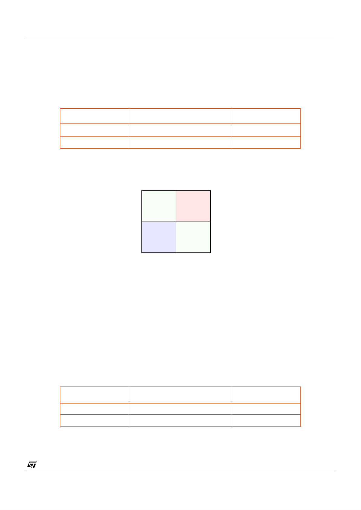
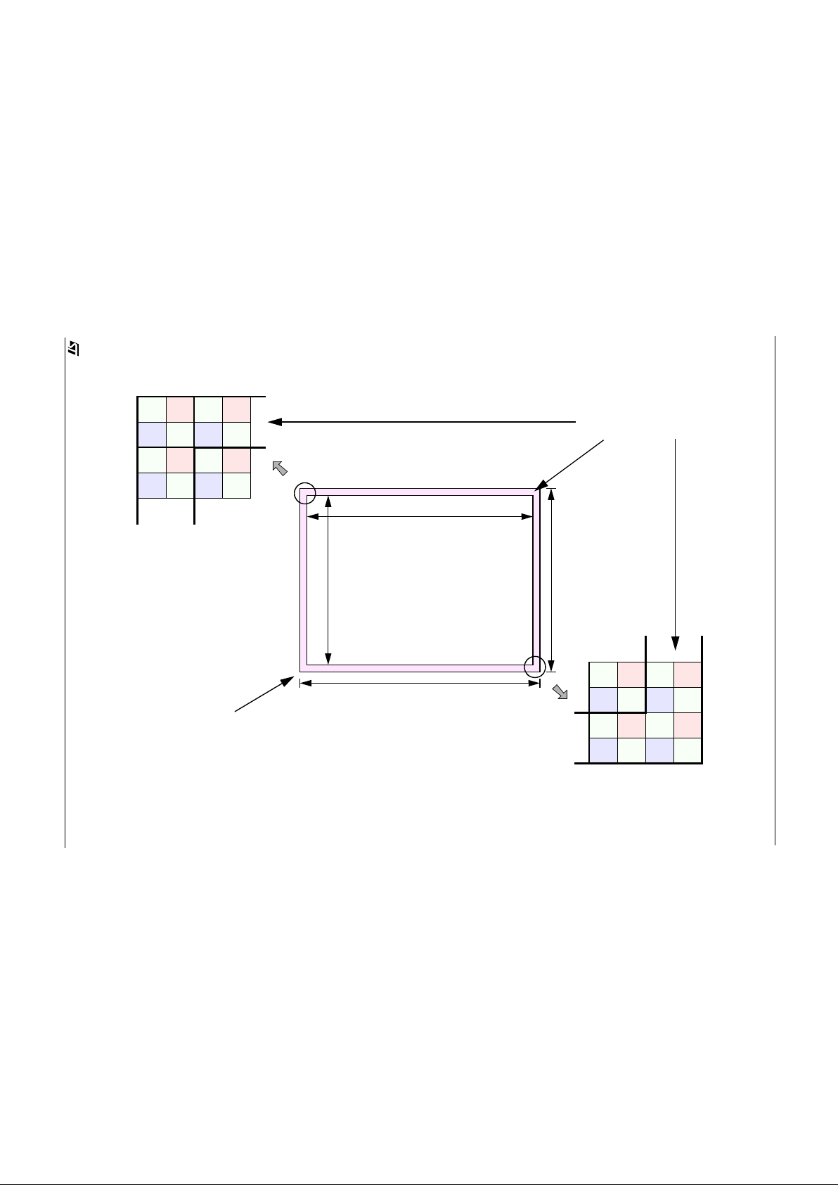
The output image format is CIF (352 x 288 pixel array). To provide the colour co-processor with the extra information
it needs for interpolation at the edges of the VV6404 pixel array, an optional border 2 pixels deep on all 4 sides of the
array can be enabled (Figure 4). The resulting image size of 356 x 292 pixels is the default power up state for this
camera module. The border option is programmable via the s erial interface.
Image read-out is either non-i nte rlac ed raster scan, or ‘shuffled’ non-interlaced rast er s ca n.
The shuffled raster scan order differs from a conventional raster in that the pixels of individual rows are re-ordered,
with the odd pixels within a row read-out first, followed by the even pixels.
This ‘shuffled’ read-out within a line, is useful in the VV6404 device as it groups pixels of the same colour (according
to the Bayer pattern - Figure 3) together, reducing cross talk between the colour channels.
NOTE:
This option is on by def ault in both VV5404 and VV6404 sensors and is controllable via the serial interface.
2.2 Frame Rate Options
Two options: 30 fps or 25 fps (Assuming a 7.15909 MHz input clock and the default clock divider setting). The number
of video lines in for each frame rate is the same (304), the slower frame rate is implemented by extending the line
period from 393 pixel periods to 471 pixel periods. 30 fps is the default option, the frame rate is programmable via the
serial interface.
Border Image size (column x row)
Disabled 352 x 288
Enabled 356 x 292 Default
Table 1 : Image Format Selection.
F rame Rate (fps) Fr ame Timing (Pixels x Lines)
25 471 x 304
30 393 x 304 default
Table 2 : Frame Rate Selection
Blue Green
Green Red
Even
Columns
(0, 2, 4,...)
Odd
Columns
(1, 3, 5,...)
Even
Rows
(0, 2, 4,...)
Odd
Rows
(1, 3, 5,...)
Figure 3 : Bayer Colourisation Pattern. (VV6404 only)
Page 7
VV5404 & VV6404
CD5404-6404F-A
7/54
Blue Green
Green Red
Blue Green
Green Red
Blue Green
Green Red
Blue Green
Green Red
Blue Green
Green Red
Blue Green
Green Red
Blue Green
Green Red
Blue Green
Green Red
355354353
352
289
291
290
288
1
3
2
0
321
0
Figure 4 : VV6404 Colourised Image Format
352 Pixels
288 Pixels
292 Pixels
356 Pixels
0, 1, 2, 3,... ... 352, 353, 354, 355
0, 1, 2, 3,... ... 288, 289, 290, 291
Border Rows and Columns
Pixel Array
Page 8
VV5404 & VV6404
CD5404-6404F-A
8/54
3. Exposure Control
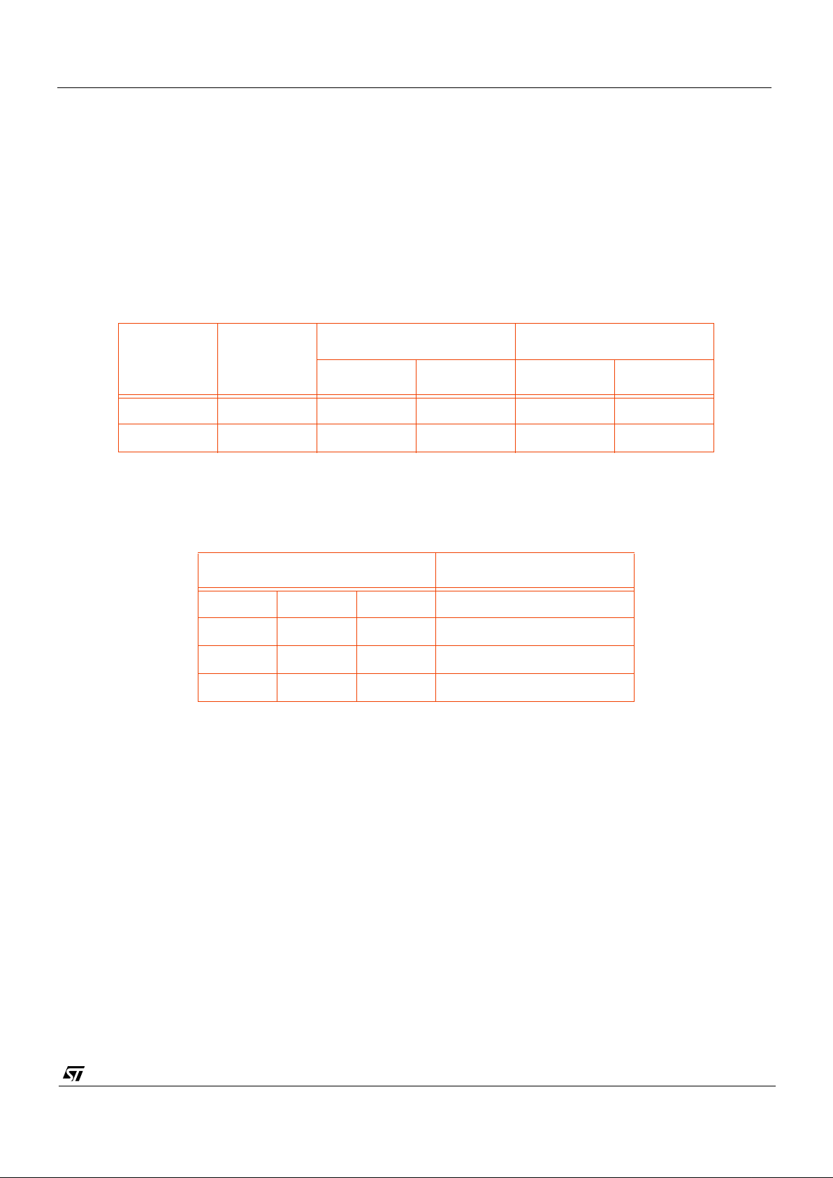
The exposur e time for a pixel and the gain of the input amplifier to the 8-bit ADC are programmable via the serial
interface. The explanation below assumes that the gain and exposure values are updated together as part of a 5 byte
serial interface auto- incr em ent seq uence.
The exposure is divided into 2 components - coarse and fine. The coarse exposure value sets the number of lines a
pixel exposes for, while the fine exposure sets the number of additional pixel clock cycles a pixel integrates for. The
sum of the two gives the overall exposure time for the pixel array.
30 fps mode: Exposure Time = (Clock Divisor) x (Coarse x 393 + Fine) x (CKI clock period)/
25 fps mode: Exposure Time = (Clock Divisor) x (Coarse x 471 + Fine) x (CKI clock period)
If an exposure value is loaded outwith the valid ranges listed in the above table the value is clipped to lie within the
above ranges.
Exposure and gain values are re-timed within the sensor to ensure that a new set of values is only applied to the
sensor array at the start of each frame. Bit 0 of the Status Register is set high when a new exposure value is written
via the serial interface but has not yet been applied to the sensor array.
There is a 1 frame latency between a new exposure value being applied to the sensor array and the results of the
new exposure value being read-out. The same latency does not exist for the gain value. To ensure that the new
exposure and gain values are aligned up correctly the sensor delays the application of the new gain value by one
frame relative to the application of the new exposure value.
To eliminate the possibi li ty of the sensor array seeing only part of the new exposure and gain setting, if the serial
interface communications extends over a frame boundary, the internal re-timing of exposure and gain data is disabled
while writing data to any lo cation in t he Exposure page of the s erial interface register map. Thus if the 5 bytes of
exposure and gain data is sent as an auto-increment sequence, it is not possible for the sensor to consume only part
of the new exposure and gain data.
Value Units
30 fps mode 25 fps mode
Min. Max. Min. Max.
Coarse Video Lines 0 302 0 302
Fine Pixel Clocks 0 356 0 434
Table 3 : Coarse and Fine Exposure Ranges.
Gain Code, G[2:0] Amplifier Gain
000 1
001 2
011 4
111 8
Table 4 : Main Gain Steps.
Page 9
VV5404 & VV6404
CD5404-6404F-A
9/54
4. Digital Video Interface Format
4.1 General descriptio n
The video interface consists of a unidirectional, tri-stateable 4-wire databus. The nibble transmission is synchronised
to the rising edge of the system clock (Figure 13).
Digital video data is 8 bits per sample, transmitted as serial pairs of parallel 4-bit nibbles (most significant nibble first)
on 4 wires.
Multiplexed with the sampled pixel data is control information including both video timing references and sensor
status/configuration data. Video timing reference information takes the form of field start characters, line start
characters, end of line characters and a line counter.
Where hexadecimal values are us ed, they ar e ind ic ate d by a subscri pt H, such as FF
H
; other values are decimal.
4.2 Embedded control data
To distinguish the control data from the sampled video data all control data is encapsulated in embedded control
sequences. These are a mi nim um of 6 words long and incl ude s a combined escape/sync character, 1 contro l word
(the ‘command byte’) and 2 words of supplementary data.
To minimise the susceptibility of the embedded control data to random bit errors redundant coding techniques have
been used to allow single bit errors in the embedded control words to be corrected. However, more serious corruption
of control words or the corruption of escape/sync characters cannot be tolerated without loss of sync to the data
stream. To ensure that a loss of sync is detected a simple set of rules has been devised. The four exceptions to the
rules are outl ined below:
1. Data containing a command words that has two bit errors.
2. Data containing two ‘end of line’ codes that are not separated by a ‘start of line’ code.
3. Data preceding an ‘end of frame’ code before a start of frame’ code has been received.
4. Data containing line that do not have sequential line numbers (excluding the ‘end of frame’ line).
If the video processor detects one of these violations then it should abandon the current frame of video.
4.2.1 The combined escape and sync character
Each embedded control sequence begins with a combined escape and sync character that is made up of three words.
The first two of these are FF
H
FFH- constituting two words that are illegal in normal data. The next word is 00H guarantee ing a cl e ar sig nal tran siti on tha t all ows a vid eo pr oc esso r to d eter mi ne t he posi tio n of the word boundaries
in the serial stream of nibbles. Combined escape and sync characters are always followed by a command word making up the four word minimum embedded control sequence.
4.2.2 The command word
The word that follows the combined escape/sync characters defines the type of embedded control data. Three of the
8 bits are used to carry the control information, four are ‘parity bits’ that allow the video processor to detect and correct
a certain level of errors in the transmission of the command words, the remaining bit is always set to 1 to ensure that
the command word is never has the value 00
H
. The coding scheme used allows the correction of single bit errors (in
the 8-bit sequence) and the detection of 2 bit errors. The three data bits of the command word are inte rpreted as
shown in Figure 5.
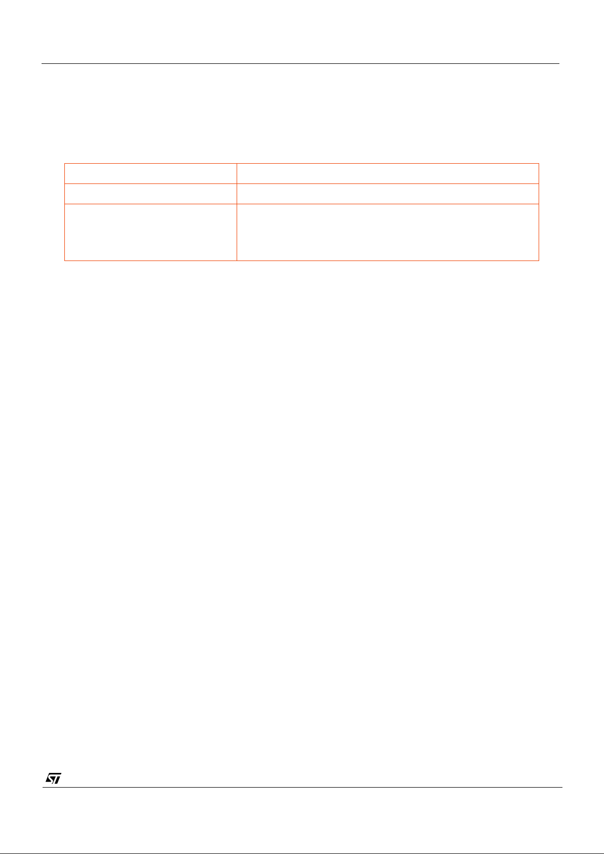
Read-out Order Progressive Scan (Non-interlaced)
Form of encoding Uniformly quantised, PCM, 8 bits per sample
Correspondence between video
signal levels and quantisation
levels:
Internally valid pixel data is clipped to ensure that 00
H
and FFH
values do not occur when pixel data is being output on the data
bus. This gives 254 possible values for each pixel (1 - 254). The
video black level co rre sp onds to code 16.
Table 5 : Video encoding parameters
Page 10

VV5404 & VV6404
CD5404-6404F-A
10/54
Figure 5 : Embedded Control Sequence
(i) Line Number (L11 MSB)
(Line Code)
Escape/Sync Sequence
Bit
76543210
Odd word parity
FHF
H
FHF
H
0H0
H
YHX
H
D
2D3
D
0D1
P2P
3
P1P
0
or (ii) If Line Code = End of Line then
Nibble X
H
Nibble Y
H
Nibble D
3
Nibble D
2
Nibble D
1
Nibble D
0
Nibble D3 = F
H
Nibble D1 = F
H
Nibble D2 = F
H
Nibble D0= F
H
Line Code
Nibble X
H
Nibble Y
H
1 C2 C1 C
0
P3 P2 P1 P
0
End of Line 10002 (8H)0000
2
(0H)
Blank Line (BL) 1001
2 (9H
) 11012 (DH)
Black line (BK) 10102 (AH) 10112 (BH)
Visible Line (VL) 1011
2 (BH
)0110
2
(6H)
Start of Frame (SOF) 1100
2 (CH
)0111
2
(7H)
End of Frame (EOF) 11012 (DH) 10102 (AH)
Reserved 1110
2 (EH
) 11002 (CH)
Reserved 1111
2 (FH
)0001
2
(1H)
Bit
76543210
C
2
1
C1C
0
L7L
8
L6PL
11
0
L10L
9
L1L
2
L0PL
5
0
L4L
3
11 1111 11
11 1111 11
Supplementary Data
Command
4-wire nibble output mode
Page 11
VV5404 & VV6404
CD5404-6404F-A
11/54
SOF
Line
2 Black Lines (BK)
7 Blank Lines (BL) 292 Visible Lines (VL)Start of Image (SOF)
BK BK BL BL BL VL VL VL VL VL VL VL VL SOF BKEOF BL
303
1234 9101112
13 299298 300 301 1303
Number
Line
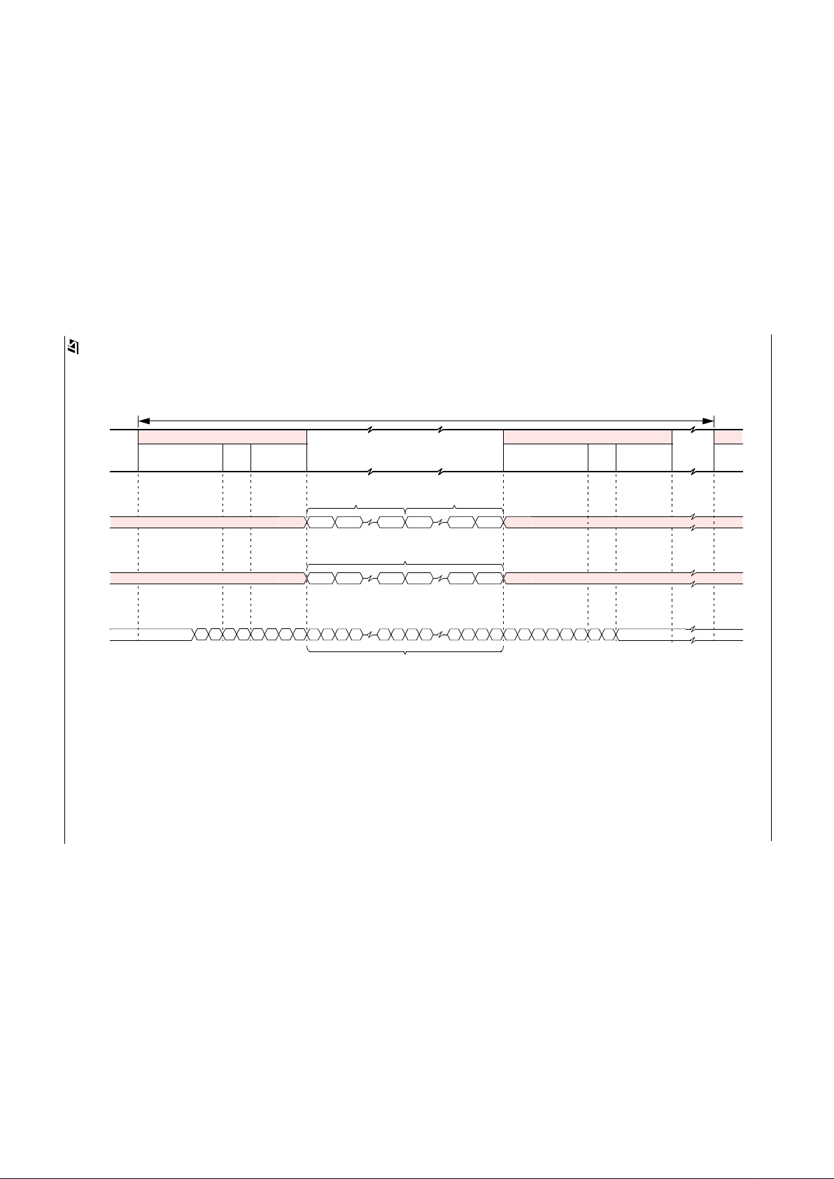
Code
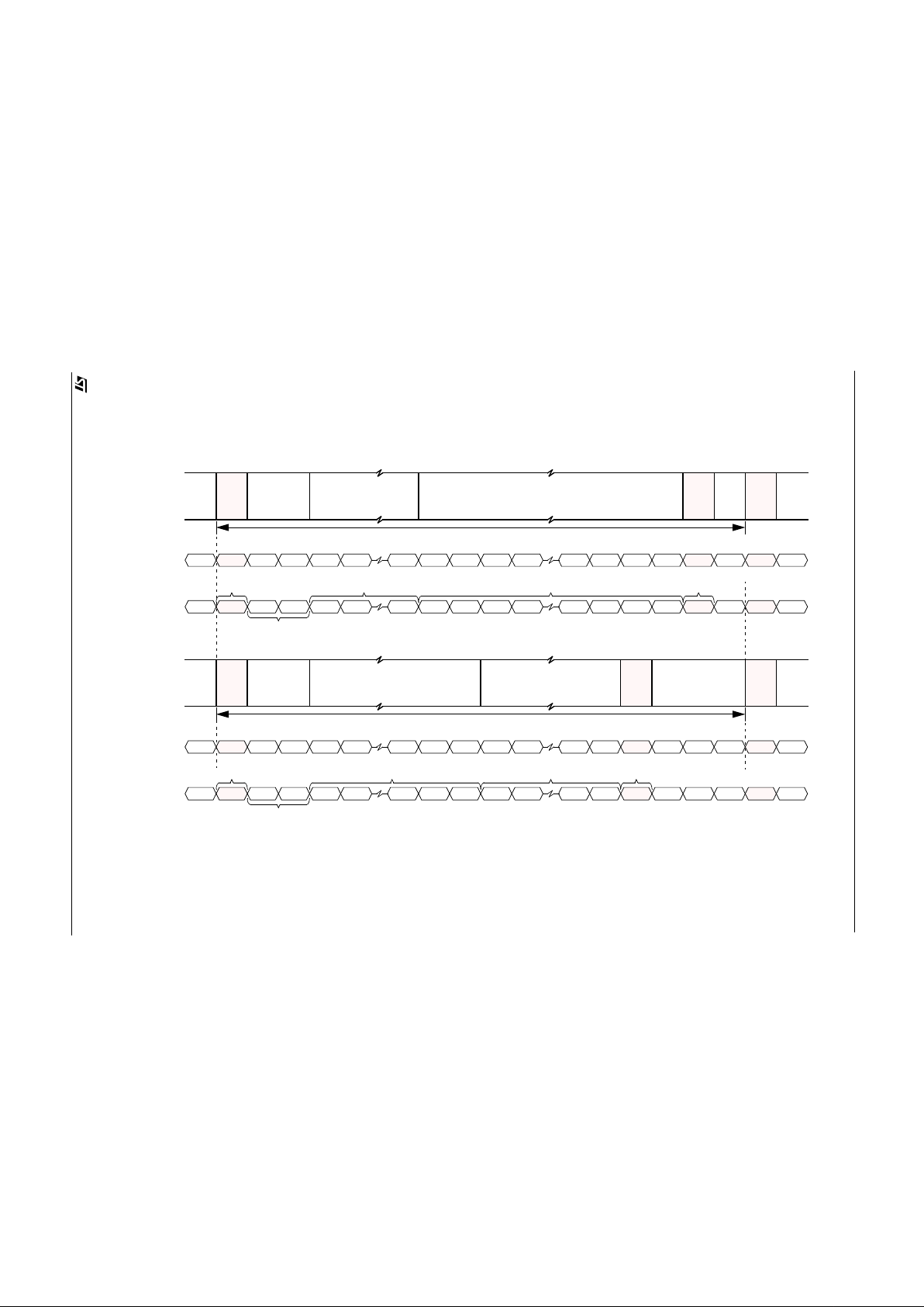
Figure 6 : Frame Formats
Start of
Blanking
End of
Image Data
Frame
Frame
Start of
Frame
Frame Period (304 Lines)
BL
Lines
Black
Lines
0 0302
Blanking
Line
End of Image (EOF)
Start of
Blanking
End of
Image Data
Frame
Frame
Start of
Frame
Lines
Black
Lines
Blanking
Lines
SOF
2 Black Lines (BK)
9 Blank Lines (BL) 288 Visible Lines (VL)Start of Image (SOF)
BK BK BL BL BL VL VL VL VL SOF BKEOF BL
303
1234 9101112
13 299298 300 301 1303
Frame Period (304 Lines)
BL
0 0302
End of Image (EOF)
BL BLBL BL
Frame Format (Border rows and columns enabled - Default) :
Frame Format (Border rows and columns disabled)) :
Line
Number
Line
Code
Page 12
VV5404 & VV6404
CD5404-6404F-A
12/54
Start of Active Video (SAV)
Line
Figure 7 : Line Data Format.
End of Active Video (EAV)
Video Data
178 Odd Pixels 178 Even Pixels
0HY
H
D1D
0
D3D
2
PMP
L
PMP
L
PMP
L
PMP
L
F
H
Line Format
PMP
L
PMP
L
Number
SAV
Line Period (393 Pixel Periods - 30 fps, 471 Pixel Periods - 25 fps)
1
3 355 0 352 354
356 Pixels
Pixel Number (Shuffled Pixel Data)
F
H
F
H
FHFHFHFH0H0H8H0
H
0HX
H
Line
Code
Escape/Sync
Sequence
Null
Characters
Line
Code
Escape/Sync
Sequence
4-wire Nibble Output Mode, D[3:0]
0
1 177 178 354 355
Pixel Number (Unshuffled Pixel Data)
P
M
= Pixel Value - Most Significant Nibble, PL = Pixel Value - Least Significant Nibble, P = 8-bit Pixel Value
(i)
(ii)
(iii)
(iv)
(v)
Blanking Line (BL)
Black Line (BK)
Visible Line (VL)
Start of Frame (SOF)
End of Frame (EOF)
P = Blanking Level (07
H
)
P = Valid Black Pixel Da ta
P = Valid Pixel Data
P = Sensor Status Data
P = Blanking Level (07
H
)
Page 13
VV5404 & VV6404
CD5404-6404F-A
13/54
The even parity bits are based on the following relationships:
1. An even number of ones in the 4-bit sequence (C
2
, C1, C0 and P0).
2. An even number of ones in the 3-bit sequence (C
2
, C1, P1).
3. An even number of ones in the 3-bit sequence (C
2
, C0, P2).
4. An even number of ones in the 3-bit sequence (C
1
, C0, P3).
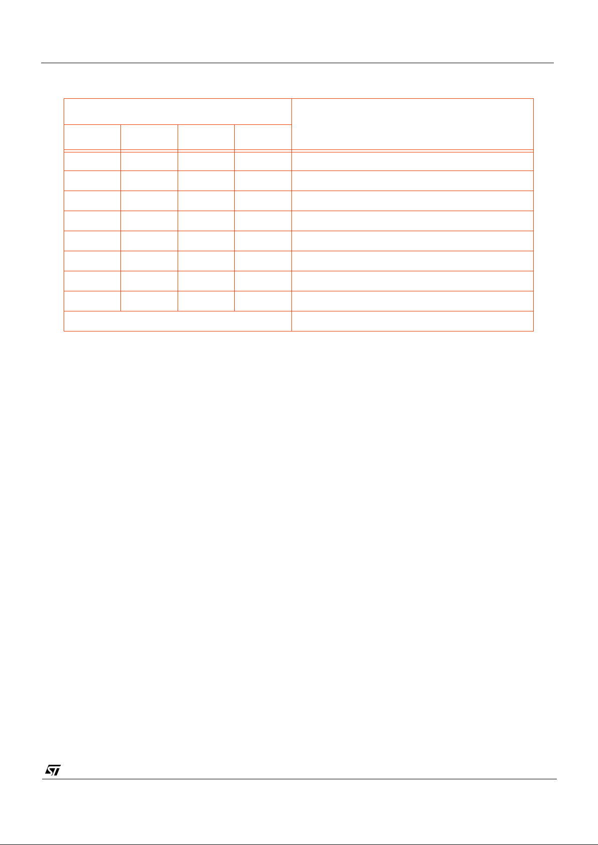
Table 6 shows how the parity bits maybe used to detect and correct 1-bit errors and detect 2-bit errors.
4.2.3 Supplementary Data
The last 2 bytes of the embedded control sequence contains supplementary data. This normally contains the current
line number except if the line code is the end of line, the 2 bytes are padded out using null characters (FF
H
). The 12
bit line number is packaged up by splitting it into two 6-bit values. Each 6-bit values is then converted into an 8-bit
value by adding a zero to the start and an odd word parity bit at the end.
4.3 Video timing reference and status/configuration data
The video sequence is made up of lines of data. Each field of data is constructed of the following data lines:
1. A start of frame line
2. 2 of ‘black lines’ (used for black level calibration)
3. 7 (9) of blank lines
4. 292 (288) active video lines
5. An end of frame line
6. 1 (3) blank lines
The numbers given in () are for when the bor de r rows and columns are not output on the databus.
Each line of data starts with an embedded control sequence that identifies the line type (as outlined in Table 3). The
control sequ enc e is the n fol low ed by two by tes that, excep t in th e cas e of the end-of-frame line, conta in a coded line
number. The line number sequences starts with the start-of-frame line at 00
H
and increments one per line up until the
end-of-frame line. Each line is terminated with an end-of-line embedded control sequence. The line start embedded
sequences must be used to recognise data lines as a number of null bytes may be inserted between data lines.
Parity Checks
Comment
P
3
P
2
P
1
P
0
1 1 1 1 Code word un-corrupted
1110P
0
corrupted, line code OK
1101P
1
corrupted, line code OK
1011P
2
corrupted, line code OK
0111P
3
corrupted, line code OK
0010C
0
corrupted, invert sense of C
0
0100C
1
corrupted, invert sense of C
1
1000C
2
corrupted, invert sense of C2
All other codes 2-bit error in code word.
Table 6 : Detection of 1-bit and 2-bit errors in the Command Word
Page 14

VV5404 & VV6404
CD5404-6404F-A
14/54
4.3.1 Blank lines
In addition to padding between data lines, actual blank data lines may appear in the positions indicated above. These
lines begin with start-of-blank-line embedded control sequences and are constructed identically to active video lines
except that they will contain only blank bytes (07
H
).
4.3.2 Black line timing
The black lines (which are used for black level calibration) are identical in structure to valid video lines except that
they begin with a start-of-black line sequence and contain either information from the sensor ‘black lines’ or blank
bytes (07
H
).
4.3.3 Valid video line timing
All valid video data is contained on active video lines. The pixel data appears as a continuous stream of bytes within
the active lines. The pixel data may be separated from the line header and end-of-line control sequence by a number
of ‘blank’ bytes (07
H
), e.g. when the border lines and pixels are disabled 07H is output in place of pixels 0, 1, 354 and
355.
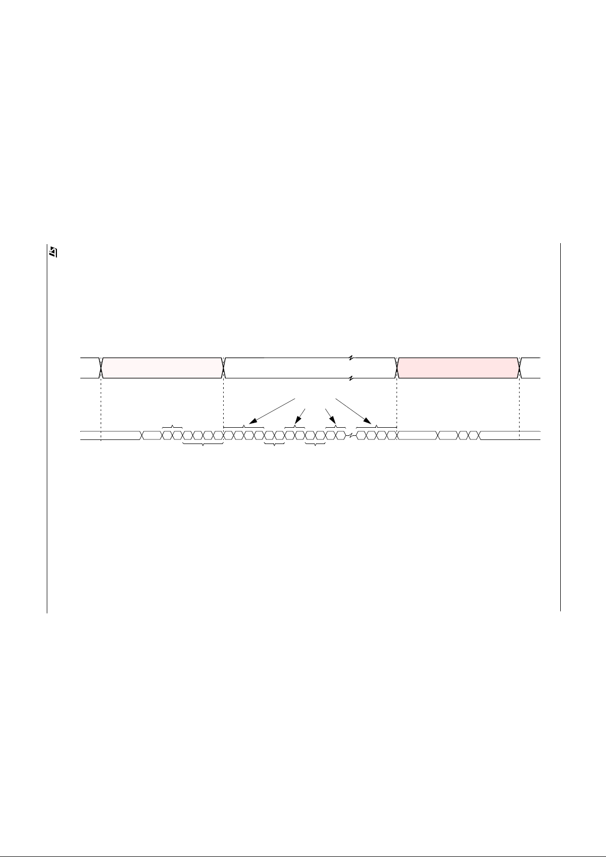
4.3.4 Start of frame line timing
The start of frame line which begins each video field contains no video data but ins tead contains the contents of all
the serial interface registers. This information follows the start-of-line header immediately and is terminated by an
end-of-line control sequence. To ensure that no escape/sync characters appear in the sensor status/configuration
informati on the code 0 7
H
is output after each serial interface value. Thus it takes 256 pixel clock periods (512 system
clocks) to output all 128 of the serial interface registers. The remainder of the 356 pixel periods of the video portion
of the line is padded out using 07
H
values. The first two pixel locations are also padded with 07H characters (Figure 8)
If a serial interface register location is unused then 07
H
is output. The read-out order of the registers is independent
of whether the pixel read-out order is shuffled or un-shuffled.
4.3.5 End of frame line timing
The end of frame line which begins each video field contains no video data. Its sole purpose is to indicate the end of
a frame.
4.4 Detection of sensor using data bus state
The video processor device must have internal pull-down terminations on the data bus. On power-up a sensor will
pull all data lines high for a guaranteed period. This scheme allows the presence of a sensor on the interface to be
detected by the video processor on power-up, and the connection of a sensor to an already power-up interface (a
‘hot’ connection).
The absence of a sens or is detected by the vide o pr ocessor seeing more than 32 consecutive nibbles of 0
H
on the
data bus. On detecting the absence of a sensor, CKI, should be disabled (held low).
The presence of a sensor is detecte d by the video processor seeing more than 32 consecutive nibbles of F
H
on the
data bus. On detecting the presence of a sensor, CKI, should be enabled.
4.5 Resetting the Sensor Via the Serial Interface
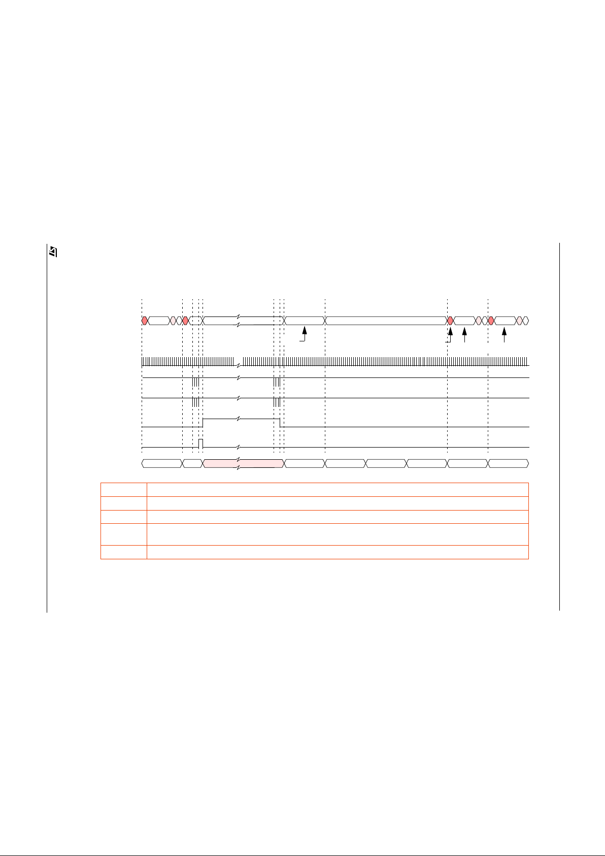
Bit 2 of setup register 0 allows the VV6404 sensor to be reset to its power-on state via the 2-wire serial interface.
Setting this “Soft Reset” bit causes all of the serial interface registers including the “Soft Reset” bit to be reset to their
default values. This “Soft Reset” leaves the sensor in low-power mode and thus an “Exit Low-Power Mode” command
(Section 4.6.2) must be issued via the serial interface before the sensor will start to generate video data (Figure 9).
4.6 Power-up, Low-power and Sleep modes
To clarify the state of the interface on power-up and in the case of a ‘hot’ connection of the interface cable the powerup state of the bus is defined below.
Page 15
VV5404 & VV6404
CD5404-6404F-A
15/54
Start of Active Video
Figure 8 : Status Line Data Format.
End of Active Video
Serial Interface Register Values
0H1
H
0H1
H
0H7
H
F
H
F
H
F
H
Output Databus, D[3:0]
1H9
H
(SAV) (EAV)
CH7
H
0H7
H
0H7H4H0
H
0H7
H
0H7
H
0H7
H
8H0
H
0
H
0
H
Start of Frame
Line Code
Line
Number 0
DeviceH
(Register 0)
DeviceL
(Register 1)
Padding
Characters
Page 16
VV5404 & VV6404
CD5404-6404F-A
16/54
Figure 9 : Resetting the VV6404 Sensor via the Serial Interface.
F
H
9H,6H,9H,6H...
N 0 1
D[3:0]
CLKI
Frame
Number
SDA
SCL
2 3 4 5
Start of Frame Line for the 1st
frame of valid video data.
Valid Video data.
SR0
SR1
SR2
SR6
SR7
setup0[2]
SR0-SR1 “Soft-Reset” Command. At the end of the command the sensor is reset and enters low-power mode.
SR2 The sensor enters low-power mode.
SR3-SR4 “Exit Low Power Mode” Command. Powers-up analogue circuits and initiates the VM6404 sensor’s 4-frame start-up sequence
SR5-SR6 1 Frame of alternating 9
H
& 6H data on D[3:0] for the video processor to determine the best sampling phase for the nibble data
(D[3:0]).
SR7-SR8 4 Frames after the “Exit Low-Power mode” command, the sensor starts outputing valid video data.
One frame of 9H & 6H data.
F
H
SR3
SR4
SR5
SR8
setup0[0]
Page 17
VV5404 & VV6404
CD5404-6404F-A
17/54
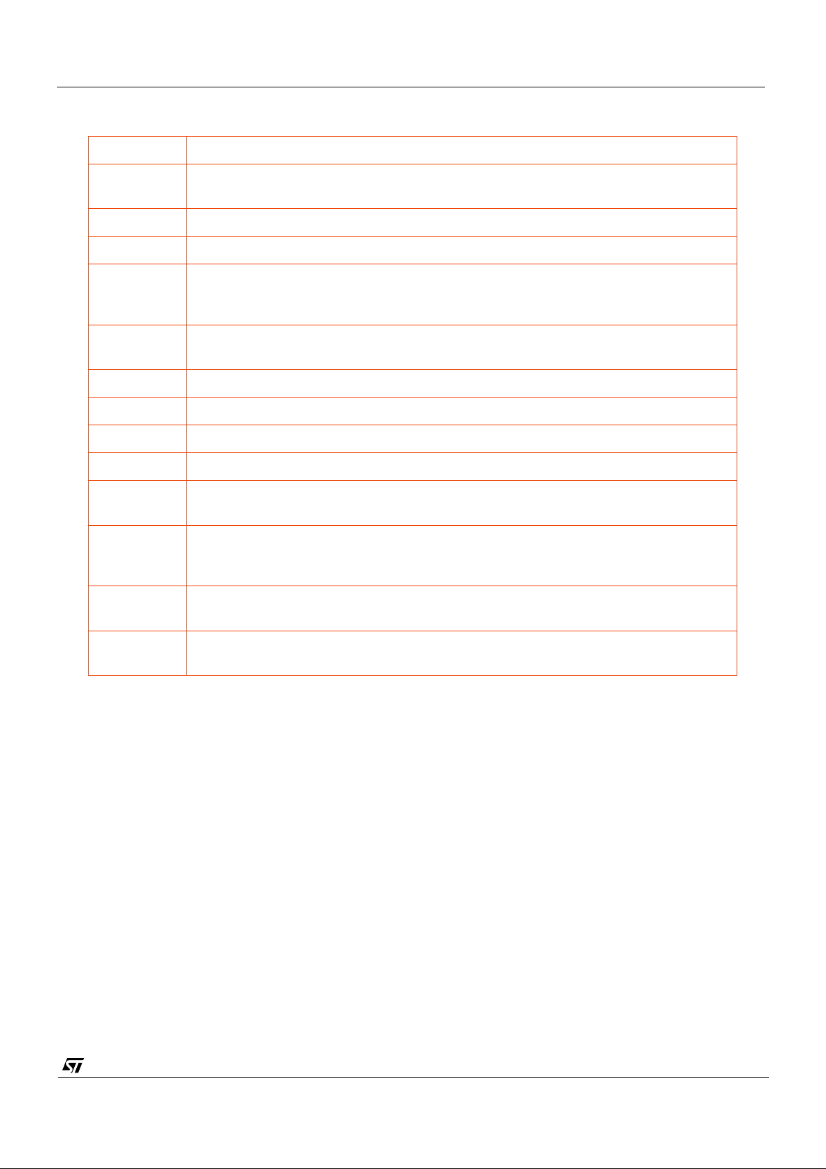
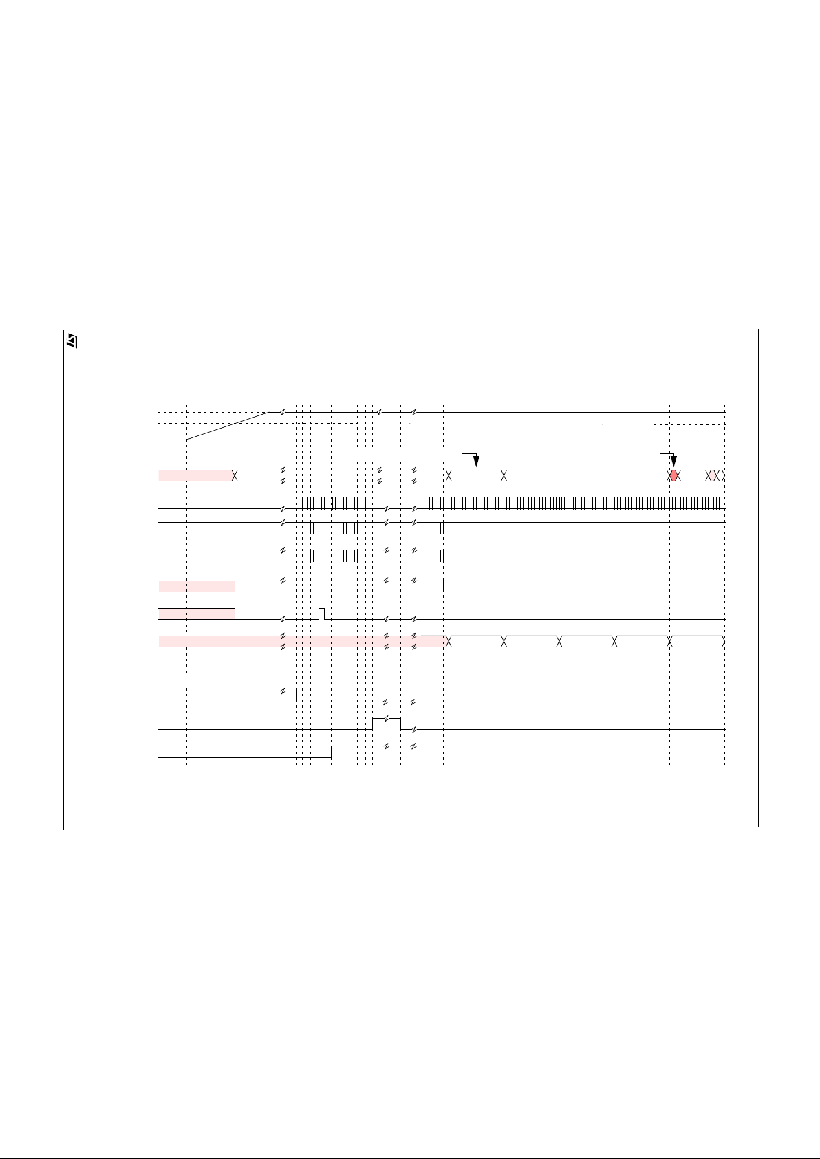
PU0 System Power Up or Sensor Hot Plugged
PU1 Sensor Internal-on Reset Triggers, the sensor enters low power mode and D[3:0] is set
to F
H
.
PU2 Video Processor released from reset.
PU3 Video Processor enables the sensor clock, CLKI.
PU4-PU5 At least 16 CLKI clock periods after CLKI has been enabled the VP sends a “Soft-Reset”
command to the sensor via the serial interface. T his e nsu r es that if a sensor is pre sen t
then it is in low-power mode.
PU6 On detecting 32 consecutive F
H
values on D[3:0], the Video Processor sets the
no_camera low.
PU7-PU8 If present, upload the sensor defect map from E
2
PROM into the Video Process or
PU9 Video Processor disables the sensor clock, CLKI.
PU10 Video Processor generates the VP_Ready interrupt.
PU11 The host software services the VP_Ready interrupt.
PU12 Host issues command to remove sensor from low-power mode. VP enables the sensor
clock, CLKI.
PU13-PU4 At least 16 CLKI clock periods after CLKI has been enabled the VP sends the “Exit Low-
Power Mode” command to the sensor via the serial interface. This initiates the sensors
4 frame start sequence.
PU15-PU16 One frame of alternating 9
H
& 6H data on D[3:0] for the video processor to determine the
best sampling phase for the nibble dat a (D[3:0]).
PU17-PU18 4 Frames after the “Exit Low-Power Mode” serial comms, the sensor starts outputing
valid video data.
Table 7 : System Power-Up or Hot-plugging Device Behaviour
Page 18

VV5404 & VV6404
CD5404-6404F-A
18/54
4.6.1 Power-Up/Down (Figure 12)
On power-up all of the data bus l ine s wil l go high Immediate l y (FH), to indicate that the device is “present” and the
device enters it low-power mode (Section 4.6.2).
When the Video Proc es s or is r es et the following sequence should b e executed to ensure that the VM6404 starts to
generate video data:
1. After the Video Processor has been released from reset, the sensor clock, CLKI, should be enabled immediately
2. After waiting for at least 16 CLKI clock cycles, a “Soft Reset” command should be issued to the sensor. This is
necessary to ensure that the sensor is brought into a known state. If the sensor is not present then the serial
interface communications by Video Processor will not be acknowledged.
3. Poll for 32 consecutive F
H
values on the data bus, if this condition is satisfied then the sensor is present. The
Video processor should set the camera_present flag.
4. Determine if the serial CMOS E
2
PROM containing the defectivity map for the sensor is present and down-load
the values.
5. Disable the sensor clock CKI.
6. The Video Processor should generate the VP_Ready interrupt.
7. Once the host software serviced the VP_Ready interrupt, then the sensor and video processor is ready to generate video data.
8. To enable video data, the host software, sets the low-power mode bit low. The video processor must enable
CLKI at least 16 CLKI clock cycles before issuing the “Exit Low-Power Mode” command via the serial interface.
After the “Exit Low-Power Mode” command has been sent the sensor will output for one frame, a continuous stream
of alternating 9
H
and 6H values on D[3:0]. By locking onto the resulting 0101/1010 patterns appearing on the data bus
lines the video processor can determine the best sampling position for the nibble data. After the last 9
H 6H
pair has
been output the databus returns to F
H
until the start of fifth frame after CKI has been enabled when the first active
frame output. After the video processor has determined the correct sampling position for the data, it should then wait
for the next start of frame line (SOF).
If the video processor detects 32 consecutive 0
H
values on the data bus, then the sensor has been removed. The
sensor clock, CKI, should be held low.
4.6.2 Low-Power Mode (Figure 10)
Under the control of the serial interface the sensor analogue circuitry can be powered down and then be powered up.
When the low-power bit is set via the serial interface, all the databus lines will go high at the end of the end of frame
line of the current frame. At this point the analogue circuits in the sensor will power down. The system clock must
remain active for the duration of low power mode.
Only the analogue circuits are powered down, the values of the serial interface registers e.g. exposure and gain are
preserved.
The internal frame timing is reset to the start of a video frame on exiting low-power mode.
In a similar manner to the previous section, the first frame after the serial comms contains a continuous stream of
alternating 9
H
and 6H to allow the video processor to re-confirm its sampling position. Then three frames latter the
first start of frame line is generated.
4.6.3 Sleep Mode (Figure 11)
Sleep mode is similar to the low-power mode, except that analogue circuitry remains powered. When the sleep
command is received via the serial interface the pixel array will be put into reset and the data lines all will go high at
the end of the current frame. Again the system clock must remain active for the duration of sleep mode.
When sleep mode is disabled, the CMOS sensor’s frame timing is reset to the start of a frame. During the first frame
after exiting from sleep mode the databus will remain high, while the exposure value propagates through the pixel
array. At the start of the second frame the first start of field line will be generated.
Page 19
VV5404 & VV6404
CD5404-6404F-A
19/54
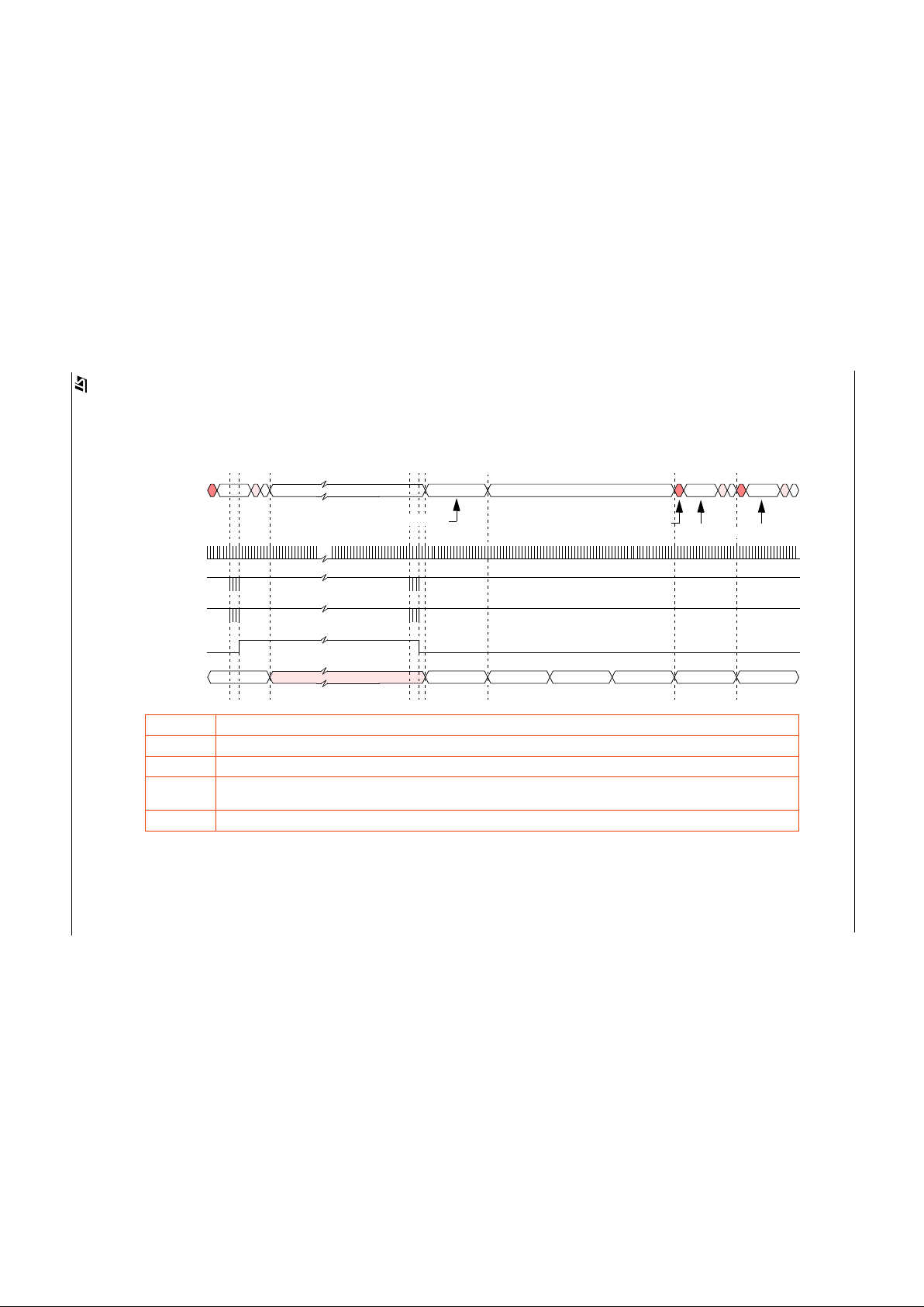
Figure 10 : Entering and Exiting Low Power Mode.
N 0 1
D[3:0]
CLKI
Frame
Number
SDA
SCL
2 3 4 5
Start of Frame Line for the 1st
frame of valid video data.
Valid Video data.
LP0
LP1
LP3
LP2
LP7
LP8
setup0[0]
LP0-LP1 “Enter Low Power Mode” Command.
LP2 At end of current frame, D[3:0] is set to F
H
and the VM6404 sensor’s analogue circuitry is powered down.
LP3-LP4 “Exit Low Power Mode” Command. Powers-up analogue circuits and initiates the VM6404 sensor’s 4-frame start-up sequence
LP5-LP6 1 Frame of alternating 9
H
& 6H data on D[3:0] for the video processor to determine the best sampling phase for the nibble data
(D[3:0]).
LP7-LP8 4 Frames after the “Exit low Power Mode” command, the sensor starts outputing valid video data.
One frame of 9H & 6H data.
F
H
F
H
9H,6H,9H,6H...
LP4
LP5
LP6
Page 20
VV5404 & VV6404
CD5404-6404F-A
20/54
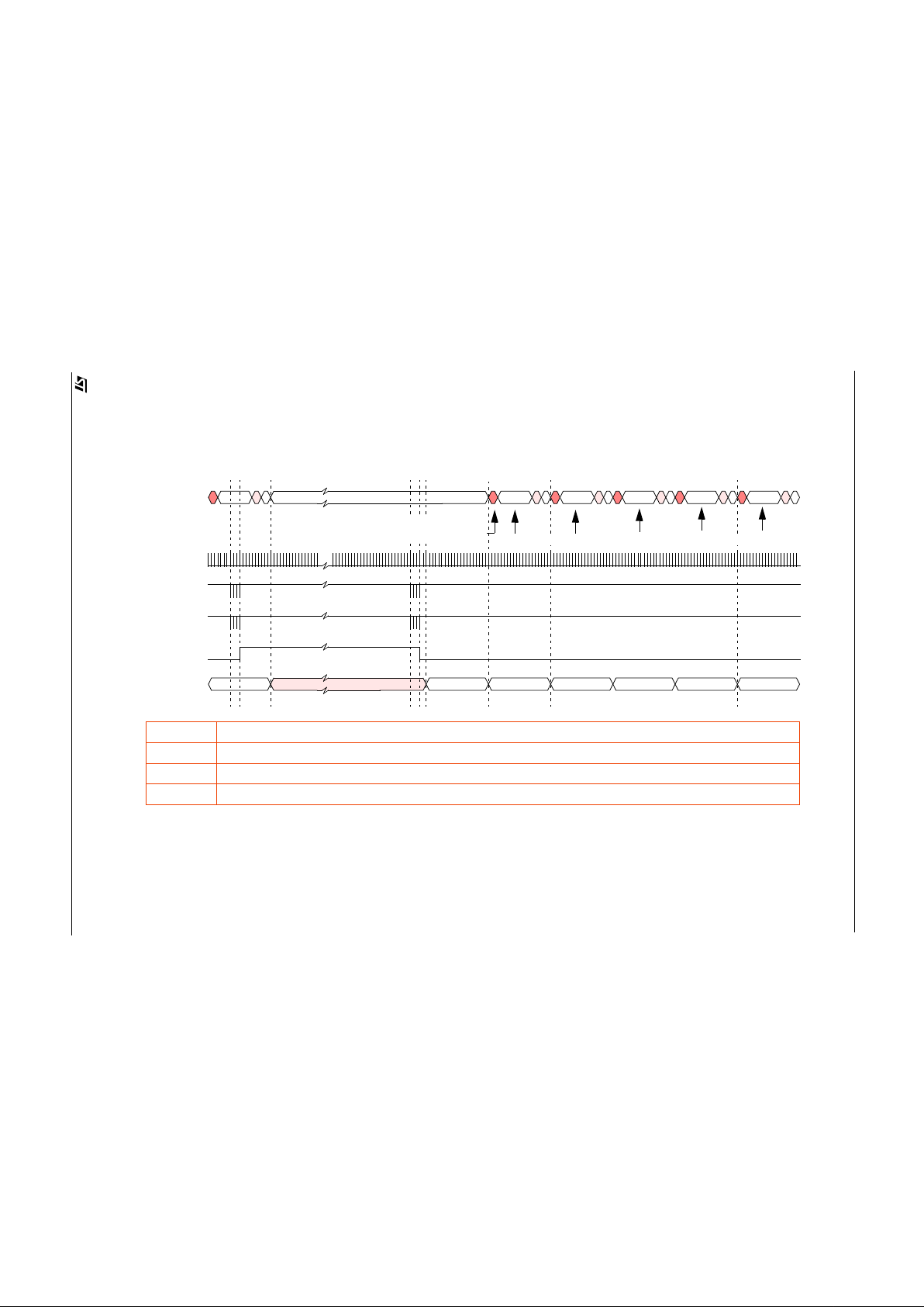
Figure 11 : Entering and Exiting Sleep Mode.
N 0 1
D[3:0]
CLKI
Frame
Number
SDA
SCL
2 3 4 5
Start of Frame Line fo r the 1 st
frame of valid video data.
Valid Video data.
SL0
SL1
SL3
SL2
SL7
setup0[1]
SL0-SL1 “Enter Sleep Mode” Command.
SL2 At end of current frame, D[3:0] is set to FH.
SL3-SL4 “Exit Sleep Mode” Command. Powers-up analogue circuits and initiates the VM6404 sensor’s 1-frame sleep start-up sequence
SL6-SL7 1 Frame after the “Exit Sleep Mode” command, the sensor starts outputing valid video data.
F
H
SL4
SL5
SL6
Page 21
VV5404 & VV6404
CD5404-6404F-A
21/54
Figure 12 : System Power-Up or Hot-plugging Device Behaviour
43
2
10
F
H
F
H
5V
0V
2.8V
9H,6H,9H,6H...
Regulated
Sensor
Power
D[3:0]
CLKI
Frame
Number
SDA
SCL
PU0
PU1
PU10
PU3
PU2
PU4
PU5
PU6
PU7
PU8
PU9
PU11
VP dev_reset
PU12
Start of Frame Line for the
1st frame of valid video data.
VP_Ready
Camera_Present
Colour Video Processor
One frame of 9H & 6H data.
PU13
PU14
PU15
PU16
PU17
PU18
setup0[2]
setup0[0]
Page 22

VV5404 & VV6404
CD5404-6404F-A
22/54
4.6.4 Appli cation of the system clock during sensor low-power modes
For successfully entry and exit into and out of low power and ‘sleep’ modes the system clock, CLKI, must remain
active for the duration of th ese modes.
4.7 Qualification of Output Data
There are two distinct ways for qualifying the data nibbles appearing of the output data bus
4.7.1 Using the External Clock signal applied to CKI
The data on the output data bus, changes on the rising edge of CKI. The delay between the video processor supplying
a rising clo ck edge and the data on the databus becoming valid, depends on the length of the cable between the
sensor and the video pr oc esso r. To allow the video processor to find the best sampling position for the data nibbles,
via the serial interface the databus can be forced to output continuously 9
H
, 6H, 9H, 6H,...
4.7.2 Data Qualification Clock, QCK
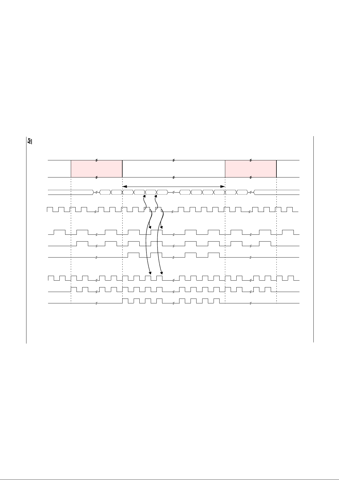
VV6404 provides a data qualification clock for the output bus. There are two frequencies for the qualification clock:
one runs at the nibble rate and the other at the pixel read-out rate. The falling edge of the fast QCK qualifies every
nibble irrespective of whether it is most or least significant nibble. For the slow QCK, the rising edge qualifies the most
significant nibbles in the output data stream and the falling edge qualifies the least significant nibbles in the output
data stream.
There are 4 modes of operation of QCK.
1. Disabled (Always low - (Default)
2. Free running - qualifies the whole of the output data stream.
3. Embedded control sequences, status data and pixel data.
4. Pixel Data Only.
The operating mode for QCK is set via the serial interface. The QCK output is tristated when OEB is high.In one of
the modes available via the serial interface the slow version of QCK will appear on the QCK pin while the fast version
of the same signal will appear on the FST pin.
In the case where the border rows and columns are disabled, there is simply no qualification pulse at that point in time
i.e. when pixels 0,1, 354 and 355 are normally output.
The QCK pin can also be configured to output the state of a serial interface register bit. This feature allows the sensor
to control external devices, e.g. stepper motors, shutter mechanisms. The configuration details for QCK can be found
in sections 5.5.7 and 5.5.8 of this document.
4.7.3 Frame Start Signal, FST
There are 3 modes of operation for th e FST pin pr og ra mma bl e via the seri al int er fac e:
1. Disabled (Always Low- Default).
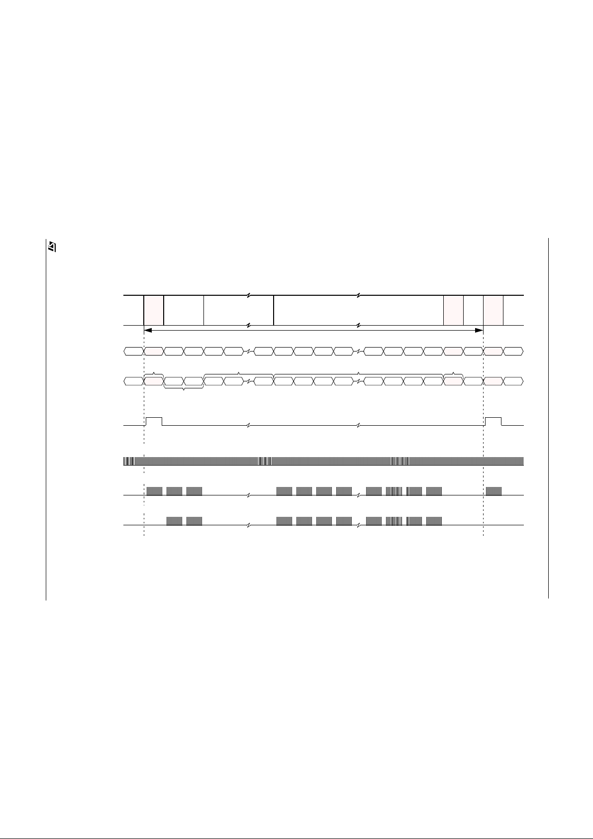
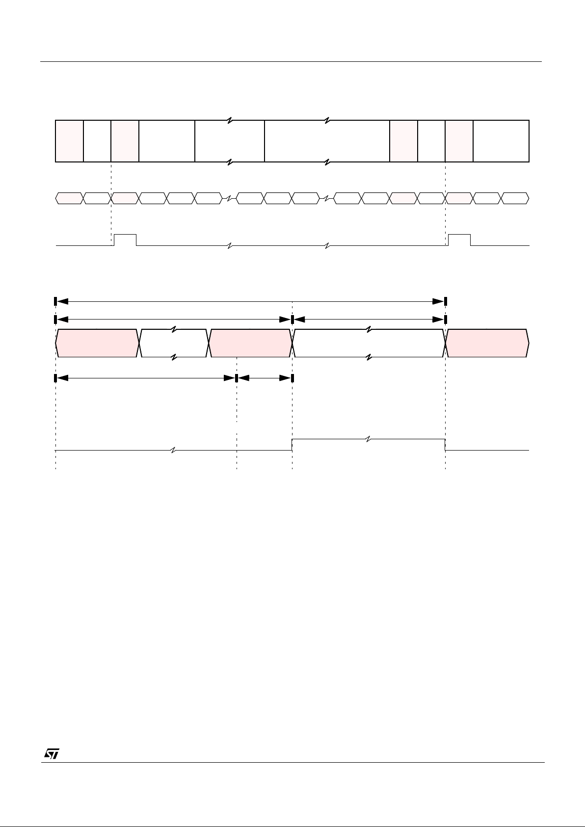
2. Frame start signal. The FST signal occurs once frame, is high for 356 pixel periods (712 system clock periods)
and qualifies the data in the start of frame line.
The FST is tristated when OEB is high.
The FST pin can also be configured to output the state of a serial interface register bit. This feature allows the sensor
to control external devices, e.g. stepper motors, shutter mechanisms.
The configuration details for FST can be found in sections 5.5.7 and 5.5.8 of this document.
Page 23
VV5404 & VV6404
CD5404-6404F-A
23/54
End of Active Video
(EAV)
Start of Active Video
(SAV)
Pixel Data
Figure 13 : Qualification of Output Data (Border Rows and Columns Enabled).
Video Data
F
H
Line Format
4-wire Nibble Output Mode - D[3:0]
D1D
0
F
H
FHF
H
PMPLPMP
L
PMPLPMP
L
Crystal Clock or external clock applied to CKI
Slow Qualification Clock, QCK
(i) Free running
(ii) Control sequences and Pixel Data
(iii) Pixel Data only
PM = Pixel Value - Most Significant Nibble, PL = Pixel Value - Least Significant Nibble, P = 8-bit Pixel Value
Fast Qualification Clock, QCK
(i) Free running
(ii) Control sequences and Pixel Data
(iii) Pixel Data only
Page 24
VV5404 & VV6404
CD5404-6404F-A
24/54
SOF
Line
2 Black Lines (BK)
7 Blank Lines (BL) 292 Visible Lines (VL)Start of Image (SOF)
BK BK BL BL BL VL VL VL VL VL VL VL VL SOF BKEOF BL
303
123 4 9101112
13 299298 300 301 1303
Number
Line
Code
Figure 14 : Frame Level Timings for FST and QCK (Border Rows and Columns Enabled).
Start of
Blanking
End of
Image Data
Frame
Frame
Start of
Frame
Frame Period (304 Lines)
BL
Lines
Black
Lines
0 0302
Blanking
Line
End of Image (EOF)
FST
QCK
Frame Format (Border rows and columns enabled - Default) :
(i) Free Running
(ii) Control plus Data
(iii) Data Only
Page 25
VV5404 & VV6404
CD5404-6404F-A
25/54
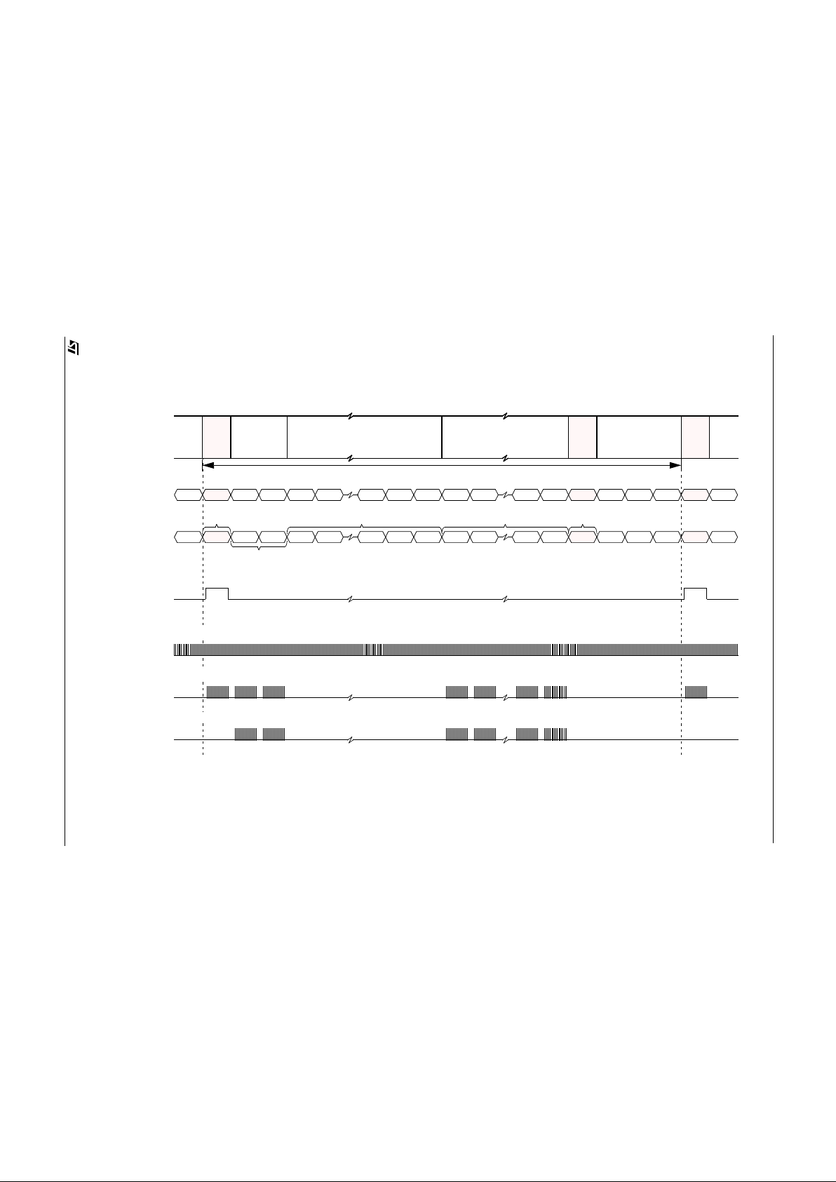
Figure 15 : Frame Level Timings for FST and QCK (Border Rows and Columns Disabled).
FST
QCK
(i) Free Running
(ii) Control plus Data
(iii) Data Only
Start of
Blanking
End of
Image Data
Frame
Frame
Start of
Frame
Lines
Black
Lines
Blanking
Lines
SOF
2 Black Lines (BK)
9 Blank Lines (BL) 288 Visible Lines (VL)Start of Image (SOF)
BK BK BL BL BL VL VL VL VL SOF BKEOF BL
303
1234 9101112
13 299298 300 301 1303
Frame Period (304 Lines)
BL
0 0302
End of Image (EOF)
BL BLBL BL
Frame Format (Border rows and columns disabled) :
Line
Number
Line
Code
Page 26
VV5404 & VV6404
CD5404-6404F-A
26/54
Line Number
303
1 2 3 9 10 11
300
Start of
Blanking
Image Data
Frame
Frame Period (304 Lines)
Lines
Black
Lines
0
FST
Frame Format (Border rows and columns enabled in example):
End of
Frame
302
Blanking
Line
301 1303
End of
Frame
Start of
Frame
0302
Blanking
Line
2
Black
Lines
SAV
FST
EAV EAVStatus Information
(i) Frame start pulse - qualifies status line informat ion.
Start of Frame Line Format:
Line Period (393 Pixel Periods - 30 fps, 471 Pixel Periods - 25 fps)
356 Pixels
37 (115) Pixels
4 Pixels
33 (111) Pixels
Figure 16 : FST Pin Waveforms.
Page 27
VV5404 & VV6404
CD5404-6404F-A
27/54
5. Serial Control Bus
5.1 General Description
Writing configuration information to the video sensor and reading both sensor status and configuration information
back from the sensor is performed via the 2-wire serial interface.
Communication using the serial bus centres around a number of registers internal to the video sensor. These
registers store sensor status, set-up, exposure and system information. Most of the registers are read/write allowing
the receiving equipment to change thei r co nten ts. O ther s (su ch as the chip id) are read only.
The main features of the serial interface include:
• Variable length read/write messages.
• Indexed addressing of information source or destination within the sensor.
• Automatic update of the index after a read of write message.
• Message abort with negative ac kno wle dge fr om the mas ter .
• Byte oriented messages.
The contents of all internal registers accessible via the serial control bus are encapsulated in each start-of-field line see Section 4.3.4.
5.2 Serial Communication Protocol
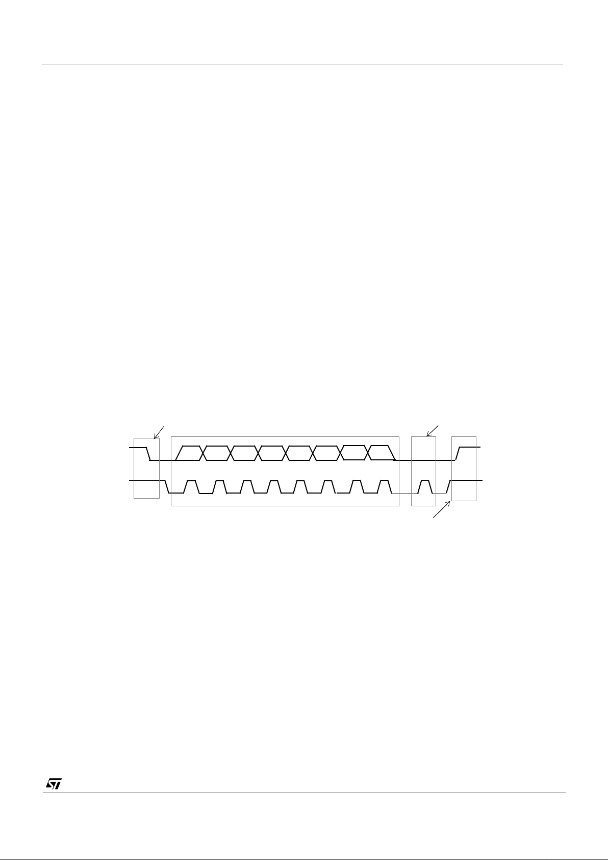
The video processor must perform the role of a communications master and the camera acts as either a slave receiver
or transmitter.The communication from host to camera takes the form of 8-bit data with a maximum serial clock video
processor frequency of up to 100 kHz. Since the serial clock is generated by the host it determines the data transfer
rate. The bus address for the sensor in VV6404 is 20
H
and for the serial E2PROM containing the defect map it is A0H.
Data transfer protocol on the bus is shown below.
5.3 Data Format
Information is packed in 8-bit packets (bytes) always followed by an acknowledge bit. The internal data is produced
by sampling
sda
at a rising edge of
scl
. The external data must be stable during the high period of
scl
. The exceptions
to this are
start
(S) or
stop
(P) conditions when
sda
falls or rises respectively, while
scl
is high.
A message contai n s at least two bytes pre ced ed by a
start
condition and followed by either a
stop
or
repeated start,
(Sr),
followed by another mes sage.
The first byte contains the device address byte which includes the data direction
read,
(r)
, ~write
, (~w), bit. The device
address of VV6404 is fixed as 0010_000_[lsb]
2
. The lsb of the address byte indicates the direction of the message.
If the lsb is set high then the master will read data from the slave and if the lsb is reset low then the master will write
data to the slave. After the
r,~w
bit is sampled, the data direction cannot be changed, until the next address byte with
a new
r,~w
bit is received.
The byte following the address byte contains the address of the first data byte (also referred to as the
index
). The
serial interface can address up to 128, byte registers. If the msb of the second byte is set the automatic increment
feature of the address index is selected.
12
7
8
A
Start condition
Stop condition
SDA
SCL
Acknowledge
P
S
3 4 56
Address or data byte
MSB LSB
Figure 17 : Serial Interface Data Transfer Protocol
Page 28
VV5404 & VV6404
CD5404-6404F-A
28/54
5.4 Message Interpretation
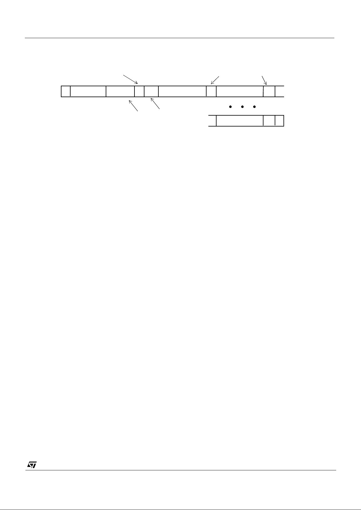
All serial interface communications with the sensor must begin with a
start
condition. If th e
start
condition is followed
by a valid address byte then further communications can take place. The sensor will acknowledge the receipt of a
valid address by driving the
sda
wire low. The stat e of the
read/~write
bit (lsb of the address byte) is stored and the
next byte of data, sampled from
sda,
can be interpreted.
During a write sequence the second byte received is an address index and is used to point to one of the internal
registers. The msbit of the following byte is the
index auto increment
flag. If this flag is set then the serial interface will
automatically increment the index address by one location after each slave acknowledge. The master can therefore
send data bytes continuously to the slave until the slave fails to provide an acknowledge or the master terminates the
write communication with a
stop
condition or sends a
repeated start, (Sr)
. If the auto increment feature is used the
master does
not
have to send indexes to accompany the data bytes.
As data is received by the slave it is written bit by bit to a serial/parallel register. After each data byte has been
received by t he sl ave, an ackn owledge is generated, the data is then stored in the internal register addressed by the
current index.
During a read message, the current index is read out in the byte following the device address byte. The next byte read
from the slave device are the contents of the register addressed by the current index. The contents of this register
are then parallel loaded into the serial/parallel register and clocked out of the device by
scl.
At the end of each byte, in both read and write message sequences, an acknowledge is issued by the receiving
device. Although VV5404 and VV6404 is always considered to be a slave device, it acts as a transmitter when the
bus master requests a read from the sensor.
At the end of a sequence of incremental reads or writes, the terminal index value in the register will be one
greater
the last location read from or written to. A subsequent read will use this index to begin retrieving data from the internal
registers.
A message can only be terminated by the bus master, either by issuing a stop condition, a repeated start condition
or by a negative acknowledge after reading a complete byte during a read operation.
S
address[7:1]
R
/W bit
A
DATA[7:0]
A
Sensor acknowledges valid address
Acknowledge from slave
INDEX[6:0]INC
P
A
A
DATA[7:0]
[0]
0 0 1 0 0 0 0
address
Auto increment
Index bit
Figure 18 : Serial Interface Data Format
Page 29

VV5404 & VV6404
CD5404-6404F-A
29/54
5.5 The Programmers Model
There may be up to 128, 8-bit registers within the camera, accessible by the user via the serial interface. They are
grouped according to function with each group occupying a 16-byte page of the location address space. There may
be up to eight such groups, although this scheme is purely a conceptual feature and not related to the actual hardware
implementation, The primary categories are given below:
• Status Registers (Read Only).
• Setup registers with bit significant functions.
• Exposure parameters that influence output image brightness.
• System functions and analogue test bit significant registers.
Any internal register that can be written to can also be read from. There are a number of read only registers that
contain device status information, (e.g. design revision details).
Names that end with H or L denote the most or least significant part of the internal register. Note that unused locations
in the H byte are packed with zeroes.
STMicroelectronic s sensors th at includ e a 2-wire serial interface are designed with a common address spa ce . If a
register parameter is unused in a design, but has been allocated an address in the generic design model, the location
is referred to as
reserved
. If the user attempts to read from any of these
reserved
locations a default byte will be
read back. In VV6404 this data is the LSByte of the device status word, address 000_0000. A write instruction to a
reserved (but unused) location is illegal and would not be successful as the device would not allocate an internal
register to the data word contained in the instruction.
Page 30
VV5404 & VV6404
CD5404-6404F-A
30/54
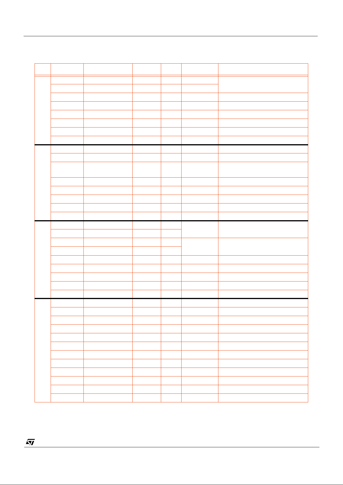
A detailed description of each register follows. The address indexes are shown as binary numbers in brackets [].
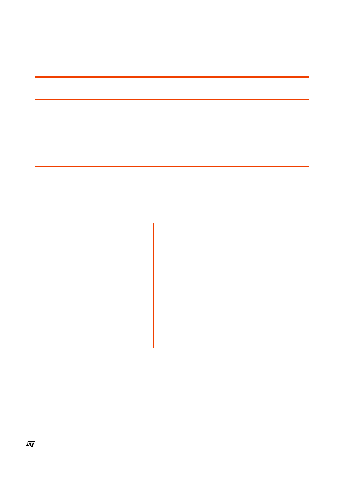
Index Name Length R/W Default Comments
Status
000_0000 deviceH 8 RO 0001 10012Chip identificat ion number
including revision indicato r
000_0001 deviceL 8 RO 0100 0000
2
000_0010 status0 8 RO 0000 1000
2
000_0011 line_countH 8 RO Current line counter MSB value
000_0100 line_countL 8 RO Current line counter LSB value
000_0101 Unused
000_011x Unused
000_1xxx Unused
Setup
001_0000 setup0 8 R/W 0 001 000 1
2
001_0001 setup1 8 R/W 1 100 000 1
2
001_0010 setup2 8 R/W 3 1 Contains pi x el counter reset
value used by external sync.
001_0011 Reserved
001_0100 setup4 8 R/W 0 FST and QCK mode selects
001_0101 setup5 8 R/W 0 FST and QCK mapping mode.
001_011x Unused
001_1xxx Unused
Exposure
010_0000 fineH 8 R/W 0 Fine exposure.
010_0001 fineL 8 R/W
010_0010 coarseH 8 R/W 302 Coarse exposure
010_0011 coarseL 8 R/W
010_0100 gain 3 R/W 0 ADC Pre-amp gain Setting
010_0101 clk_div 2 R/W 0 Clock division
010_0110 Unused
010_0111 Unused
010_1xxx Unused
System
111_0000 Reserved
111_0001 Reserved
111_0010 Reserved
111_0011 Unused
111_0100 Reserved
111_0101 Reserved
111_0110 cr 8 R/W 0000 0000
2
Control Register
111_0111 as0 8 R/W 0100 0100
2
ADC Setup Register
111_1000 Reserved
111_1001 Unused
111_101x Unused
111_11xx Unused
Table 8 : Serial Interface Address Map.
Page 31
VV5404 & VV6404
CD5404-6404F-A
31/54
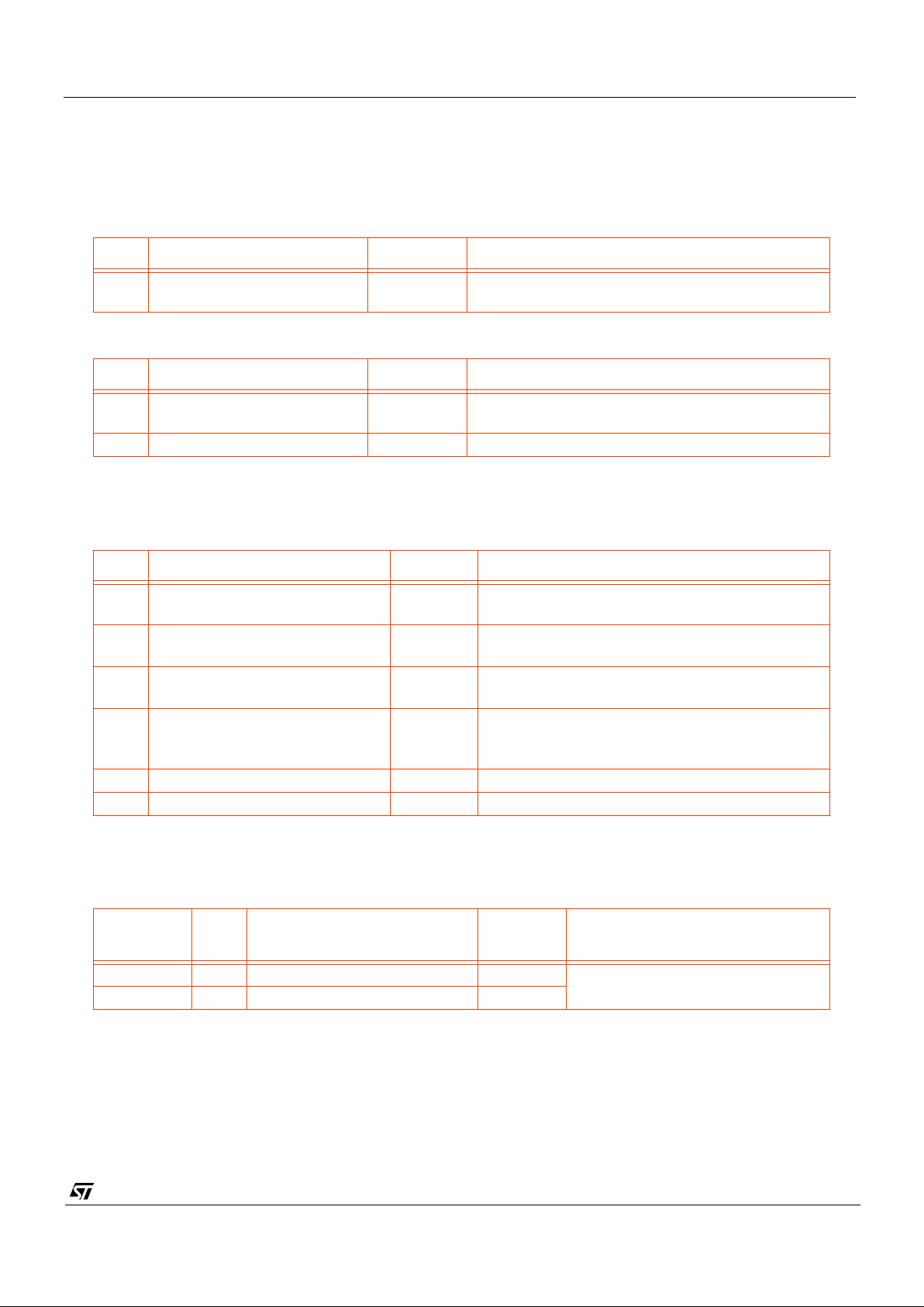
5.5.1 DeviceH [000_00002] and DeviceL [00 0_ 00012]
These registers provide read o nly i nform ati on that identi fie s the sens or ty pe that ha s been coded a s a 12bit num ber
and a 4bit mask set revision identifier. The device identification number for VV6404 is 404 i.e. 0001 1001 0100
2
.
The
initial mask revision identifier is 0 i.e. 0000
2
.
5.5.2 Status0 [000_00102]
5.5.3 Line_count_H [000_0011
2
] & Line_count_L [000_01002]
Bits Function Default Comment
7:0 Device type identifier 0001 10012Most significant 8 bits of the 12 bit code identifying
the chip type.
Table 9 : DeviceH [000_00002]
Bits Function Default Comment
7:4 Device type identifier 0100
2
Least sign ificant 4 bits of the 12 bit code ide ntifying
the chip type.
3:0 Mask set revision identifier 0000
2
Table 10 : DeviceL [000_00012]
Bit Function Default Comment
0 Exposure value update pending 0 Exposure sent but not yet consumed by the
exposure controller
1 Gain value update pending 0 Gain value sent but not yet consumed by the
exposure controller
2 Clock divisor update pending 0 Clock divisor sent but not yet consumed by the
exposure controller
3 Black cal fail flag 0 If the black calibration has failed this flag will be
raised. It will stay active until the last line of the
next
successful
black calibration.
4 Odd/even frame 1 The flag will toggle state on alternate frames
7:5 Unused 000
Table 11 : Status0 [000_00102]
Register
Index
Bits Function Default Comment
000_0011
2
7:0 Current line count MSB - Displays current line count
000_0100
2
7:0 Current line count LSB -
Table 12 : Current Line Counter V alue.
Page 32
VV5404 & VV6404
CD5404-6404F-A
32/54
5.5.4 Setup0 [001_00002]
5.5.5 Setup1 [001_0001
2
]
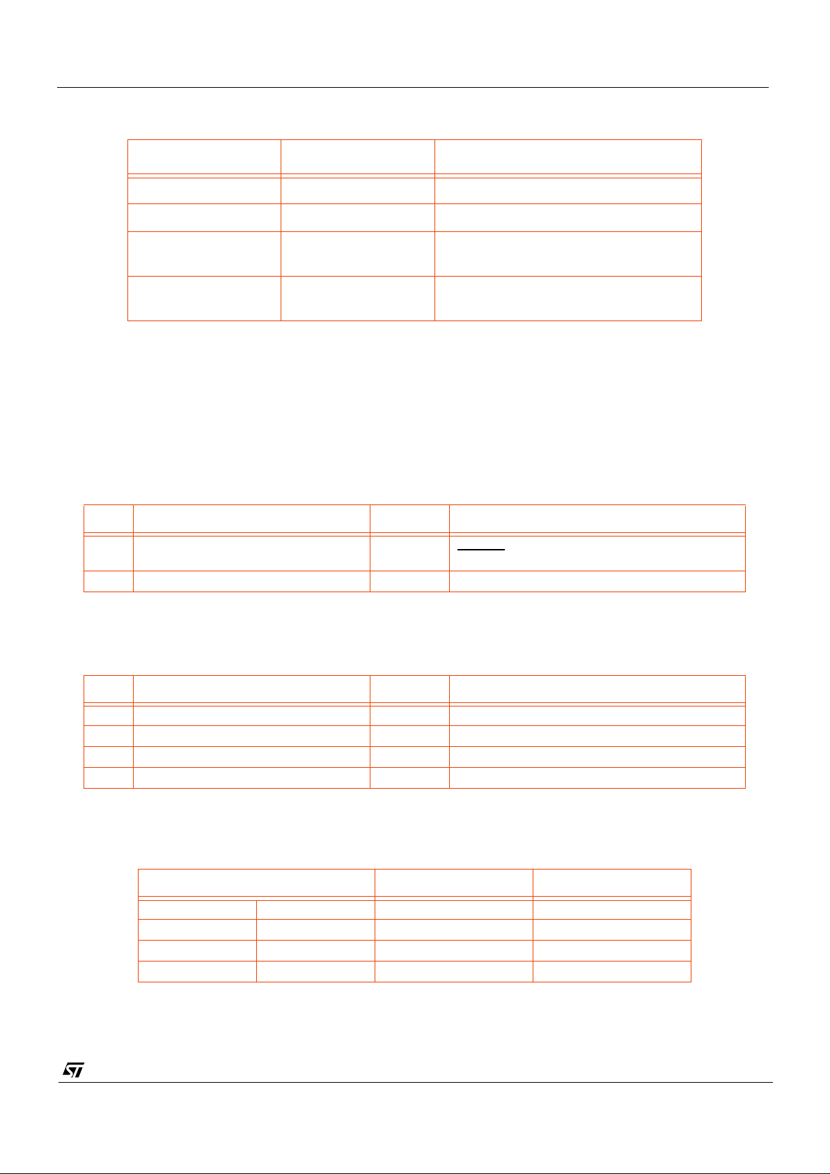
Bit Function Default Comment
0 Low Power Mode:
Off
/On
1 Powers down the se ns or arr ay . The output
databus goes to F
H
. On power-up the sensor
enters low power mode.
1 Sleep Mode:
Off
/On
0 Puts the sensor array into reset. The output
databus goes to F
H
.
2 Soft Reset
Off
/On
0 Setting this bit resets the sensor to its power-up
defaults. This bit is also reset.
3Frame Rate select:
25 fps or
30 fps
1
4 Tri-state output data bus
Outputs Enabled
/Tristate
0 On power up the data output pads D[3:0] are
enabled by default.
7:5 unused
Table 13 : Setup0 [001_00002]
Bit Function Default Comment
1:0 Black calibration mode selection 10 Black calibration trigger selection. Default
setting bases decision on result of monitor
test. See table below
2 reserved
3 Enable immediate clock division
update.
Off
/On
0 Allow manual change to clock division to be
applied immediately
4 Enable immediate gain update.
Off
/On
0 Allow manual change to gain to be applied
immediately
5 Enable addi tional black lines (li nes
3-9)
Off
/On
0 If enabled this bit will also enable the line
immediately following the end of frame line
6 Border rows and columns:
Masked or
Output
1 These extra pixels/rows are used in colour
processing
7 Pixel read-out order:
Unshuffled or
Shuffled
1 It is strongly recommended to use shuffled
read-out.
Table 14 : Setup1 [001_00012]
Page 33
VV5404 & VV6404
CD5404-6404F-A
33/54
If the gain change trigger option has been selected then care should be taken when writing the new gain value if the
immediate gain update
option has been selected. It is strongly advised that the user should
not
write a new gain
value between line 0 (the status line) and line 9 (the last black calibration line). If the gain values are written in a timed
manner then no restriction applies.
5.5.6 Setup2 [001_0010
2
]
5.5.7 Setup4 [001_0100
2
]
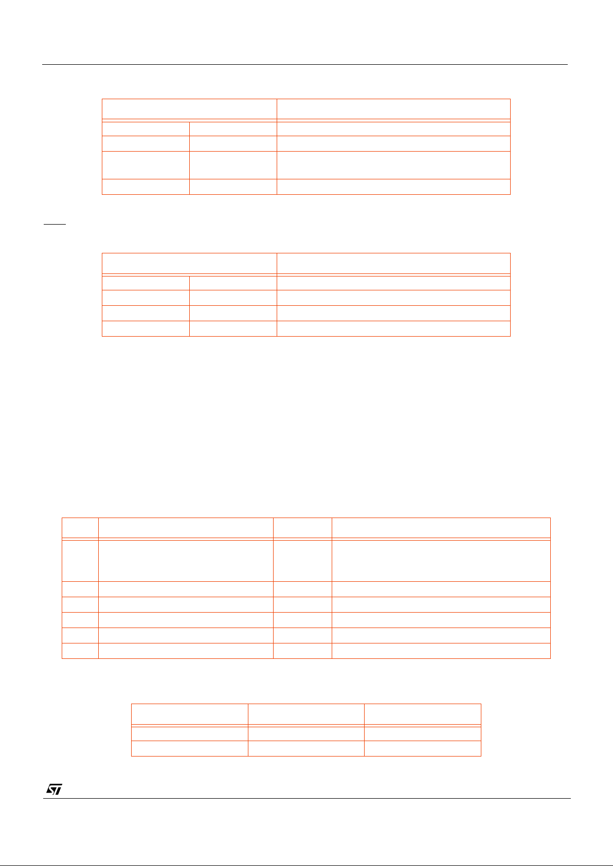
Black Cal Mode[1] Black Cal Mode[0] Comment
0 0 No black calibration
01
Always
trigger black calibration
1 0 Black calibration triggered by a
failed
monitor test
1 1 Trigger black calibratio n only if the gain
setting changes
Table 15 : Black Calibration Mode
Bit Function Default Comment
5:0 Pixel counter reset value 31
NOTE:
For proper synchronisation this regis-
ter should be written with the value 30.
7:6 Unused
Table 16 : Setup2[001_00102]
Bit Function Default Comment
1:0 FST/QCK pin modes 0 Selection of FST, QCK pin data
3:2 QCK modes 0 When to output QCK
5:4 Reserved 0 reserved for LST modes in other sensors
7:6 FST modes 0
Table 17 : Setup4[001_01002]
FST/QCK pin mode[1:0] FST pin QCK pin
00 FSTSlow QCK
01 FST Fast QCK
1 0 Fast QCK Slow QCK
1 1 Invert of Fast QCK Fast QCK
Table 18 : FST/QCK Pin Selection
Page 34
VV5404 & VV6404
CD5404-6404F-A
34/54
The option to enable the qclk during the data and control period of the line
must not be selected if monochrome
(shuffled or unshuffled) video has been selected.
5.5.8 Setup5 [001_01012]
It is important to note that although the output buffer driver strengths can be selected by writing to this register the
programmed values
cannot
be read back by the serial interface.
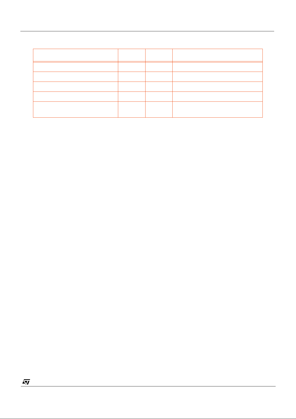
QCK mode[1:0] QCK state
00Off
0 1 Free Running
1 0 Valid during data and control period of line
(see
note)
1 1 Valid only during data period of line
Table 19 : QCK Modes
Note:
Not currently verified. Contact STMicroelectronics for further information if this mode is to be used.
FST mode[1:0] FST state
00Off
0 1 On - qualifies the status line
10Reserved
11Unallocated
Table 20 : FST Modes
Bit Function Default Comment
0 Map serial interface register bits
values on to the QCK and FST pins
Off
/On
0
1 Serial Interface Bit for QCK pin 0
2 Serial Interface Bit for FST pin 0
3 Output driver strength select 1 Default setting selects 4mA driver
4 Output driver strength select 0 Default setting selects 4mA drivers
7:5 Unused 0
Table 21 : Setup4[001_01012]
Mapping Enable FS T pin QCK pin
0FSTQCK
1 su5[2] su5[1]
Table 22 : FST/QCK Pin Selection
Page 35
VV5404 & VV6404
CD5404-6404F-A
35/54
5.5.9 Exposure Control Registers [010_00002] - [010_10012]
There is a set of programmable registers which controls the sensitivity of the sensor. The registers are as follows:
1. Fine exposure.
2. Coarse exposure tim e.
3. Gain.
4. Clock division.
The gain parameter does not affect the integration period rather it amplifies the video signal at the output stage of the
sensor core.
Note:
The external exposure (coarse, fine, clock division or gain) values do not take effect immediately. Data from
the serial interface is read by the exposure algorithm at the start of a video frame. If the user reads an exposure value
via the serial interface then the value reported will be the data as yet unconsumed by the exposure algorithm, because
the serial interface logic locally stores all the data written to the sensor.
Between writing the exposure data and the point at which the data is consumed by the exposure logic, bit 0 of the
status register is set. The gain value is updated a frame later than the coarse, fine and clock division parameters,
since the gain is applied directly at the video output stage and does not require the long set up time of the coarse and
fine exposure and the clock division.
To eliminate the possibi li ty of the sensor array seeing only part of the new exposure and gain setting, if the serial
interface communications extends over a frame boundary, the internal re-timing of exposure and gain data is disabled
while writing data to any lo cation in t he Exposure page of the s erial interface register map. Thus if the 5 bytes of
exposure and gain data is sent as an auto-increment sequence, it is not possible for the sensor to consume only part
of the new exposure and gain data.
The range of some parameter values is limited and any value programme d out-with this range will be clipped to the
maximum allowed.
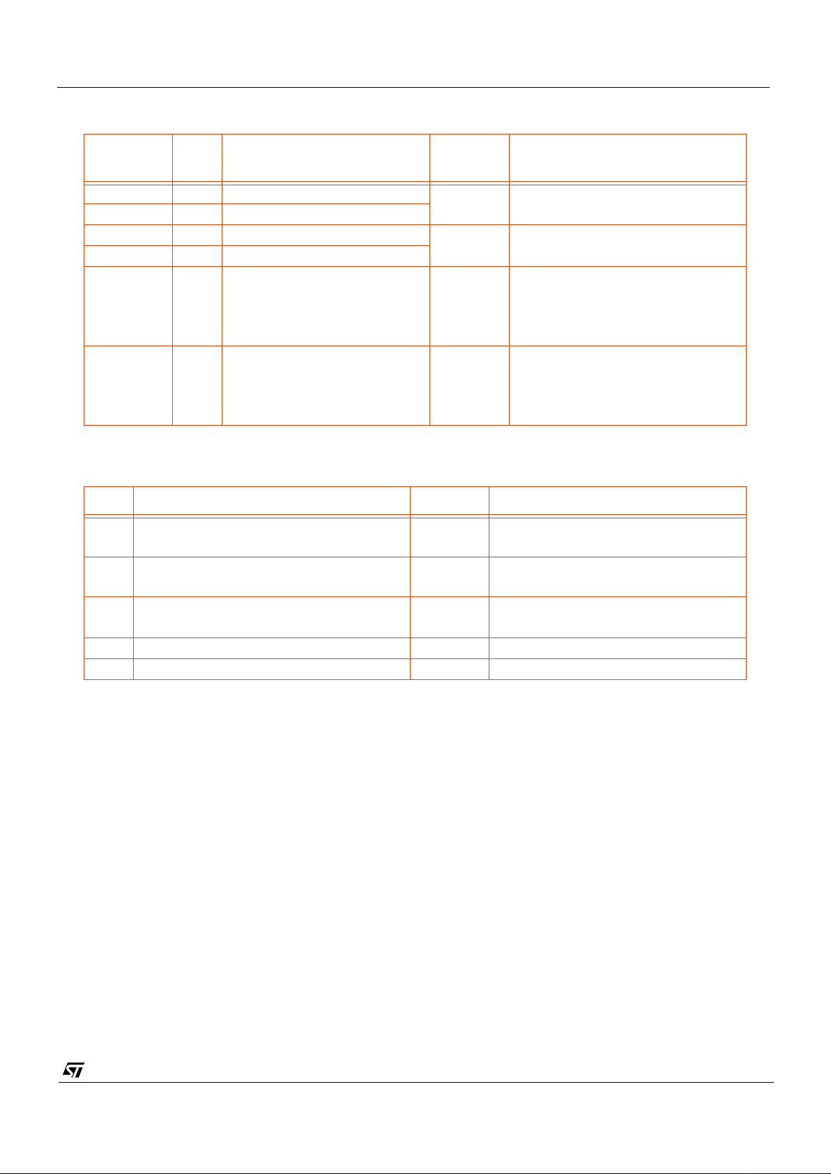
oeb_composite su5[4] su5[3] Comments
0 0 0 Drive strength = 2mA
0 0 1 Default drive strength = 4mA
0 1 0 Drive strength = 6mA
0 1 1 unallocated
1 x x Outputs are not being driven therefore
driver strength is i rre l evant
Table 23 : Output driver strength selection
Page 36
VV5404 & VV6404
CD5404-6404F-A
36/54
Notes:
1. The enable signal enabling the external ADC functionality is the logical OR of CR0[0] bit and the invert of the
ADCVDD pin.
2. The low-power select signal for the analogue circuitry is the logical OR of PD0[0] and Setup0[0].
Register
Index
Bits Function Default Comment
010_0000
2
7:0 Fine MSB exposure value 0 Maximum mode dependent: 360
(30fps) / 438 (25 fps)
010_0001
2
7:0 Fine LSB exposure value
010_0010
2
7:0 Coarse MSB exposure value 302 Maximum: 302
010_0011
2
7:0 Coarse LSB exposure value
010_0100
2
2:0 Gain value 0 000: Gain = 1
001: Gain = 2
011: Gain = 4
111: Gain = 8
010_0101
2
1:0 Clock divisor value 0 00: Pixel clock = CLKI clock/2
01: Pixel clock = CLKI clock/4
10: Pixel clock = CLKI clock/8
11: Pixel clock = CLKI clock/16
Table 24 : Exposure, Clock Rate and Gain Registers
Bit Function Default Comment
0 Standby
Off
/On
0 Powers down ALL analogue circuitry
1 Power Down - ADC
Off
/On
0
2 Power Down - ADC Top Reference
Off
/On
0
5:3 Reserved
7:6 Unused
Table 25 : Control Register CR [111_01102]
Page 37
VV5404 & VV6404
CD5404-6404F-A
37/54
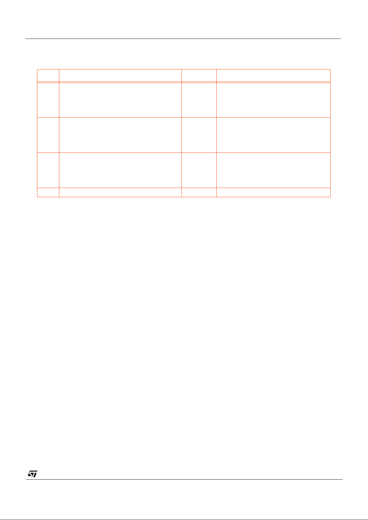
5.5.10 ADC Setup Register AS0 [111_01112]
Bit Function Default Comment
1:0 ADC Clock Fine Delay Setting
0 ns
/ 4 ns / 8 ns / 16 ns
00 00: Clock Delay = 0 ns (Default)
01: Clock Delay = 4 ns
10: Clock Delay = 8 ns
11: Clock Delay = 16 ns
3:2 ADC Clock Phase Delay Setting
0° /
90
°
/ 180° / 270
°
01 00: Phase Delay = 0
°
01: Phase Delay = 90° (Default)
10: Phase Delay = 180
°
11: Phase Delay = 270
°
5:4 PCK Clock Fine Delay Setting
0 ns
/ 4 ns / 8 ns / 16 ns
00 00: Clock Delay = 0 ns (Default)
01: Clock Delay = 4 ns
10: Clock Delay = 8 ns
11: Clock Delay = 16 ns
7:6 Reserved 1
Table 26 : ADC Setup Register AS0 [111_01112]
Page 38
VV5404 & VV6404
CD5404-6404F-A
38/54
5.6 Types of messages
This section gi ves guidelines on t he basic operations to read data from and write data to the serial interface.
The serial interface supports variable length messages. A message may contain no data bytes, one data byte or many
data bytes. This data can be written to or read from commo n or different locations within the sensor. The range of
instructions available are detailed below.
• Write no data byte, only sets the index for a subsequent read message.
• Single location multiple data write or read for monitoring (real time control)
• Multiple location, multiple data read or write for fast information transfers.
Examples of these operations are given below. A full description of the internal registers is given in the previous
section. For all examples the slave address used is 32
10
for writing and 3310 for r ea d in g . The w rite address in cl ude s
the read/write bit (the lsb) set to zero while this bit is set in the read address.
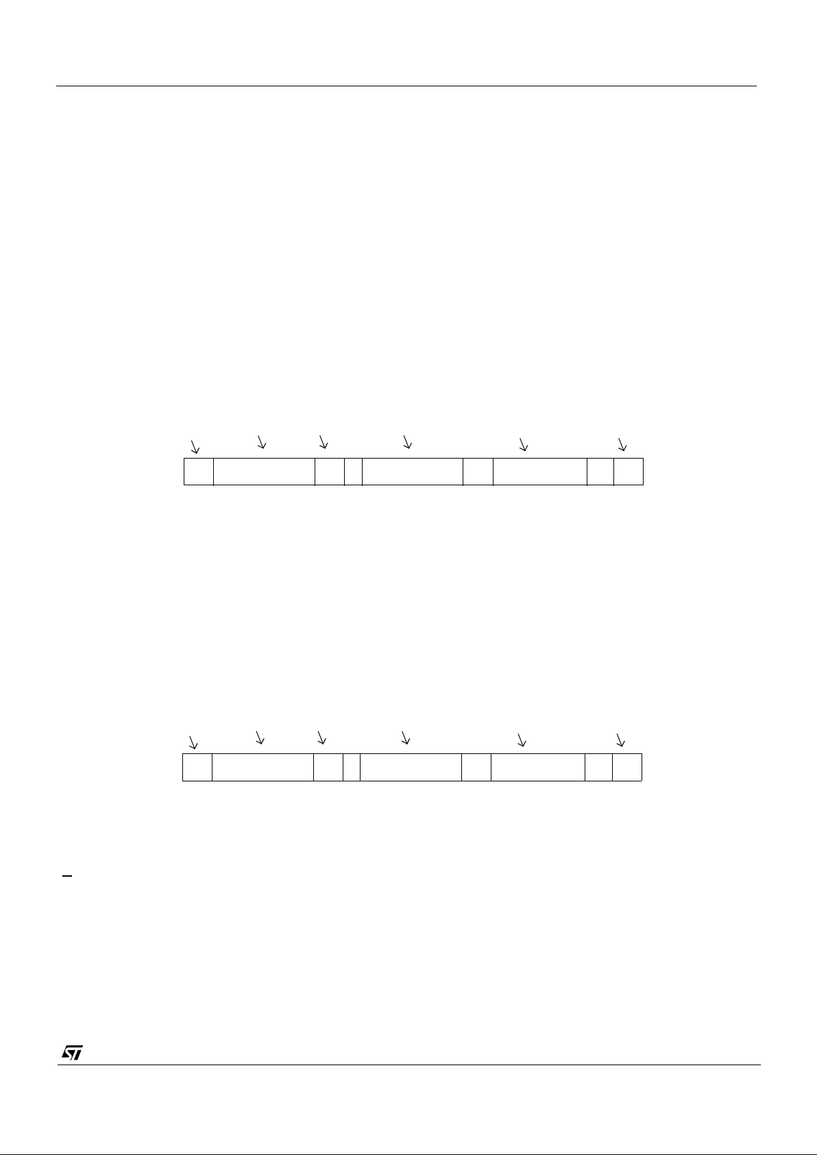
5.6.1 Single location, single data write.
When a random value is written to the sensor, the message will look like this:
In this example, the
fineH
exposure register (index = 3210) is set to 8510. The r/w bit is set to zero for writing and the
inc
bit (msbit of the index byte) is set to zero to disable automatic increment of the index after writing the value. The
address index is preserv ed and may be us ed by a subseq uen t read . The write mess age is termi na ted with a stop
condition from the master.
5.6.2 Single location, single data read.
A read message always contai ns the ind ex used to get the first byt e.
This example assumes that a write message has already taken place and the residual index value is 32
10
. A value of
85
10
is read fr om th e
fineH
exposure register. Note that the read message is terminated with a negative acknowledge
(A
) from the master: it is not guaranteed that the master will be able to issue a stop condition at any other time during
a read message. This is because if the data sent by the slave is all zeros, the
sda
line cannot rise, which is part of the
stop condition.
5.6.3 No data write followed by same location read.
When a location is to be read, but the value of the stored index is not known, a write message with no data byte must
be written first, specifying the index. The read message then completes the message sequence. To avoid
relinquishing the se rial to bus to anot her mast er a repeate d star t con dit ion is ass er ted between the write and read
messages. In this example, the
gain
value (index = 3610) is read as 1510:
Figure 19 : Single location, single write.
S 3210 A 0 3210 A 85
10
A P
Start
Device
Ack
address
Index Data
Stop
Figure 20 : Single location, single read.
S 3310 A 0 3210 A 85
10
A P
Start
Device
Ack
address
Index Data
Stop
Page 39
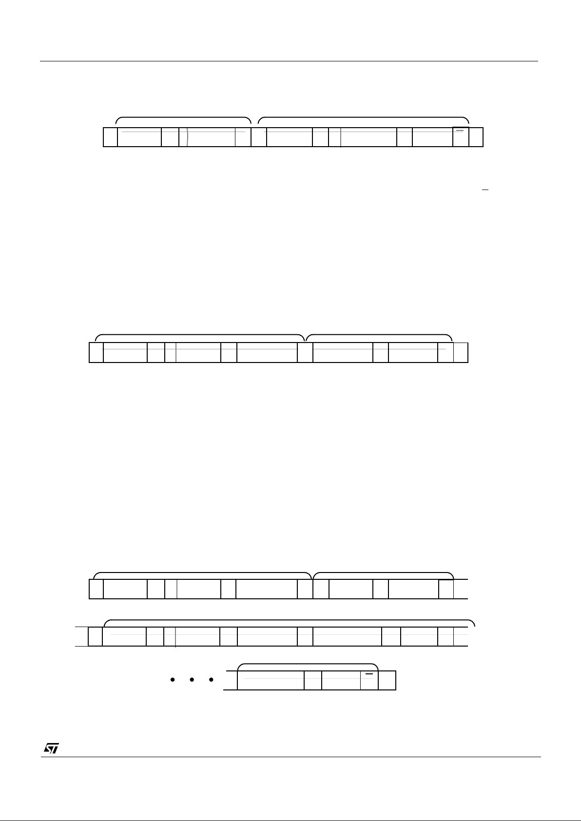
VV5404 & VV6404
CD5404-6404F-A
39/54
As mentioned in the previous example, the read message is terminated with a negative acknowledge (A) from the
master.
5.6.4 Same location multiple data write.
It may be desirable to write a succession of data to a common location. This is useful when the status of a bit,(e.g.
requesting a new black calibration), must be toggled.
The message sequence indexes
setup1
register. If bit 1 is toggled low, high low this will initiate a fresh black
calibration. This is achieved by writing three consecutive data bytes to the sensor. There is no requirement to re-send
the register index before each data byte.
5.6.5 Same location multiple data read
When an exposure related value (
fineH, fineL, coarseH, coarse L, gain or clk_div
) is written, it takes effect on the
output at the beginning of the next video frame, (remember that the application of the
gain
value is a frame later than
the other exposure parameters). To signal the consumption of the written value, a flag is set when any of the exposure
or gain registers are wr itten and is reset at the start of the next frame. This flag appears in
status0
register and may
be monitored by the bus master. To speed up reading from this location, the sensor will repeatedly transmit the current
value of the register, as long as the master acknowledges each byte read.
In the next example, a
fineH
exposure value of 0 is written, the status register is addressed (no data byte) and then
constantly read until the master terminates the read message.
Figure 21 : No data write followed by same location read.
S
A
Sr A
A
A
P
32
10
36
10
33
10
36
10
1510A
0
0
No data write Read index and data
SA 010AA A32
10
17
10
2
10
0
10
A0
Write
setup1
Turn off ABC
Toggle “Force Black Cal.”.
P
Figure 22 : Same location multiple data write.
SA 0AA A32
10
33
10
32
10
0
10
A0
Sr A AA A33
10
0
10
111A0
Sr
Write
fineL
with zero Address the status0 reg.
A
10A
Read continuously...
...until flag reset
P
Figure 23 : Same location multiple data read.
Page 40
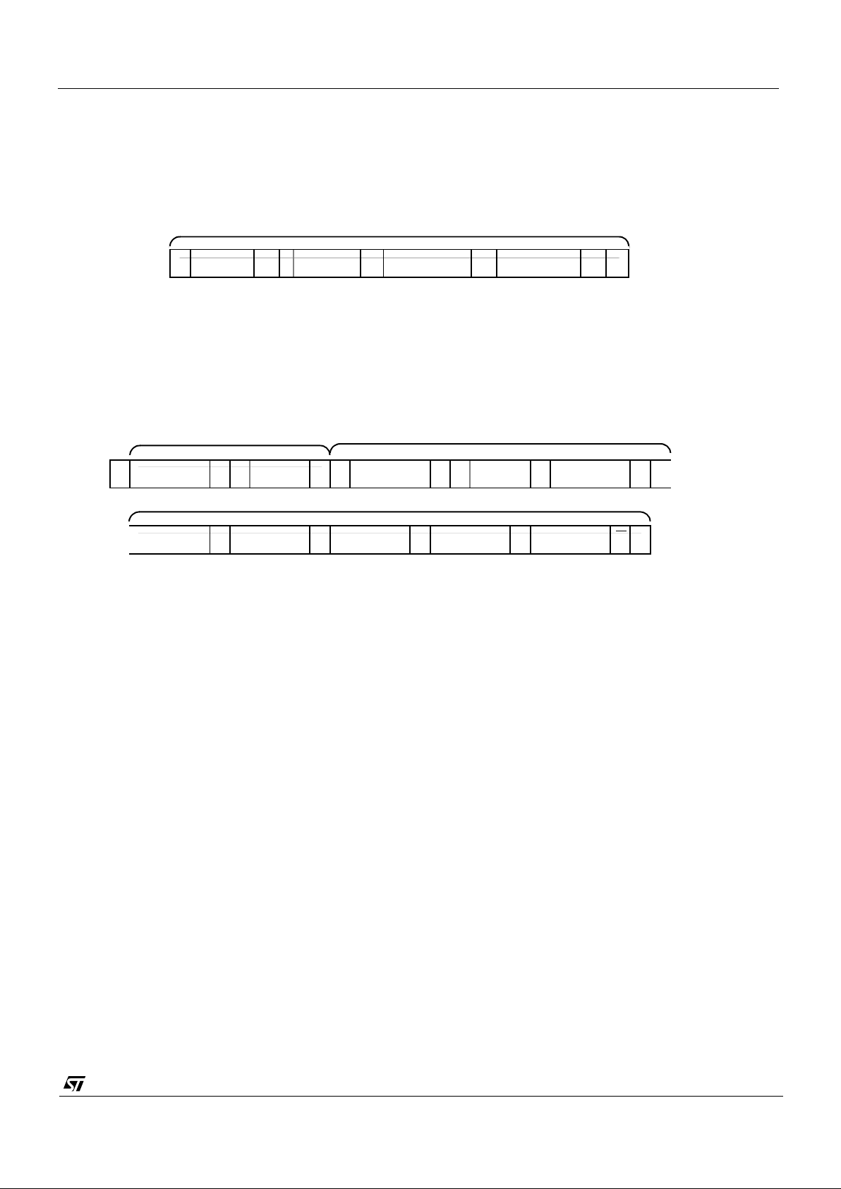
VV5404 & VV6404
CD5404-6404F-A
40/54
5.6.6 Multiple location write
If the automatic increment bit is set, (msb of the index byte), then it is possible to write data bytes to consecutive
adjacent internal registers without having to send explicit indexes prior to sending each data byte. An auto-increment
write to the black calibration DAC registers with their default values is shown in the following example.
.
5.6.7 Multiple location read
In the same manner, multiple locations can be read with a single read message. In this example the index is written
first, to ensure the exposure related registers are addressed and then all six are read
Note that a stop condition is not required after the negative acknowledge from the master.
S A 128
16
AAA32
10
113
10
128
16
1
Incremental write
P
Figure 24 : Multiple location write.
Incremental read
SAA32
10
32
10
1 Sr 33
10
AA32
10
1
fineH
A
A
P
fineL coarseH coarseL gain clk_div
AAAA
No data write
Incremental read
Figure 25 : Multiple location read.
Page 41
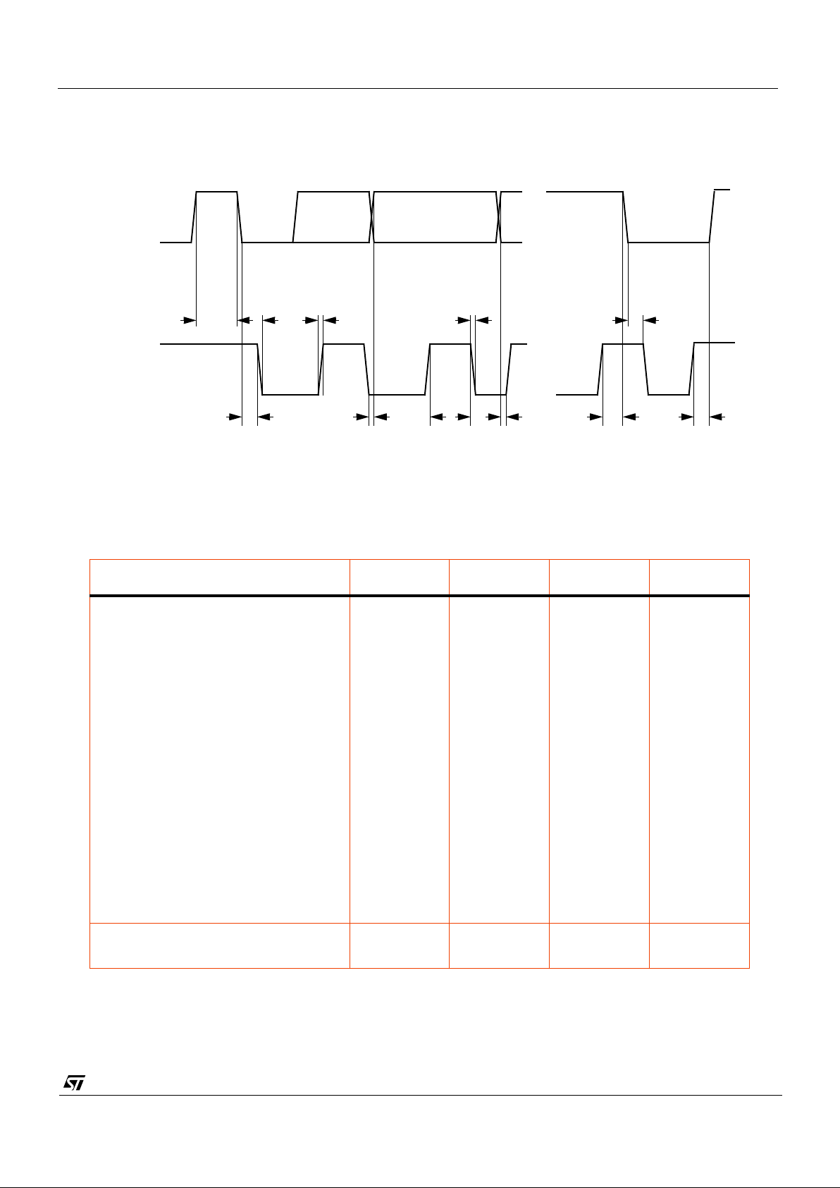
VV5404 & VV6404
CD5404-6404F-A
41/54
5.7 Serial Interface Timing
NOTE 1: With 200pF capacitive load. It is recommended that pull-up resistors of 2.2k - 4.7k are fitted to both SDA
and SCL lines.
Parameter Symbol Min. Max. Unit
SCL clock frequency fscl 0 100 kHz
Bus free time between a
stop
and a
start
tbuf 2 - us
Hold time for a repeated
start
thd;sta 80 - us
LOW period of SCL tlow 320 - us
HIGH period of SCL thigh 160 - us
Set-up time for a repeated
start
tsu;sta 80 - us
Data hold time thd;dat 0 - us
Data Set-up time tsu;dat 0 - ns
Rise time of SCL, SDA tr - 300 (note1) ns
Fall time of SCL, SDA tf - 300 (note1) ns
Set-up time for a
stop
tsu;sto 80 - us
Capacitive load of each bus line (SCL,
SDA)
Cb - 200 pF
Table 27 : Serial Interface Timing Characteristics
SDA
SCL
thd;sta
tr
thightftsu;datthd;dat tsu;sta tsu;sto
...
...
thd;statlowtbuf
stopstartstop start
all values referred to the minimum input level (high) = 3.5V, and maximum input level (low) = 1.5V
Figure 26 : Serial Interface Timing Characteristics
Page 42
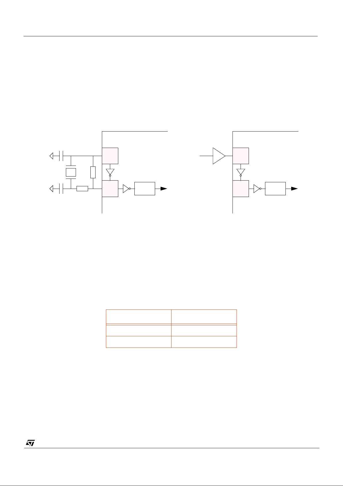
VV5404 & VV6404
CD5404-6404F-A
42/54
6. Clock Signal
VV5404 and VV6404 generate a system clock when a quartz crystal or ceramic resonator circuit is connected to the
CLKI and CLKO pins. The device can also be driven directly from an external clock source driving CLK.
If CLKI is generated for the video sensor by the receiving device it must be active during serial interface
communications for at least 16 clock cycles before the serial communications start bit and for at least 16 cycles after
the serial communications stop bit.
The synchronisation input, SIN, synchronises the clock divider logic in addition to the main clock generation and the
video timing control block.
.
For greater flexibility the input frequency can be divided by 2, 4, 8 or 16 to select the pixel clock frequency. The clock
divisor serial register selects the input clock frequency divisor.
The clock signal must be a square wave with a 50% (+/- 10%) mark:space ratio. Table 28 specifies the maximum and
minimum pixel clock frequencies for the module. Table 29 and Table 29 specify the relationship between the input
clock, CLKI, and the pixel clock frequency for the different settings of the sensor’s internal clock divider.
This translates into a maximum input clock frequency of 7.15909 MHz if a clock divisor of 2 is used (the default - Table
29). Thus if a 14.31818 MHz crystal is used, only the 4, 8 and 16 clock divisors should be used (Table 29).
MHz
Minimum Pixel Rate 0.44744
Maximum Pixel Rate 3.57954
Table 28 : Maximum and Minimum Pixel Rates
X1
C2
C1
R1
32
31
VV5/6404
CMOS
Clock
Source
R2
C1 = C2 = 47 pFR1 = 1 M
Ω
R2 = 510
Ω
X1 = 14.31818 MHz
CLK
CLOCK
DIVISION
CLKI
CLKO
Driver
32
31
VV5/6404
CLK
CLOCK
DIVISION
CLKI
CLKO
Figure 27 : Camera Clock Sources
Page 43
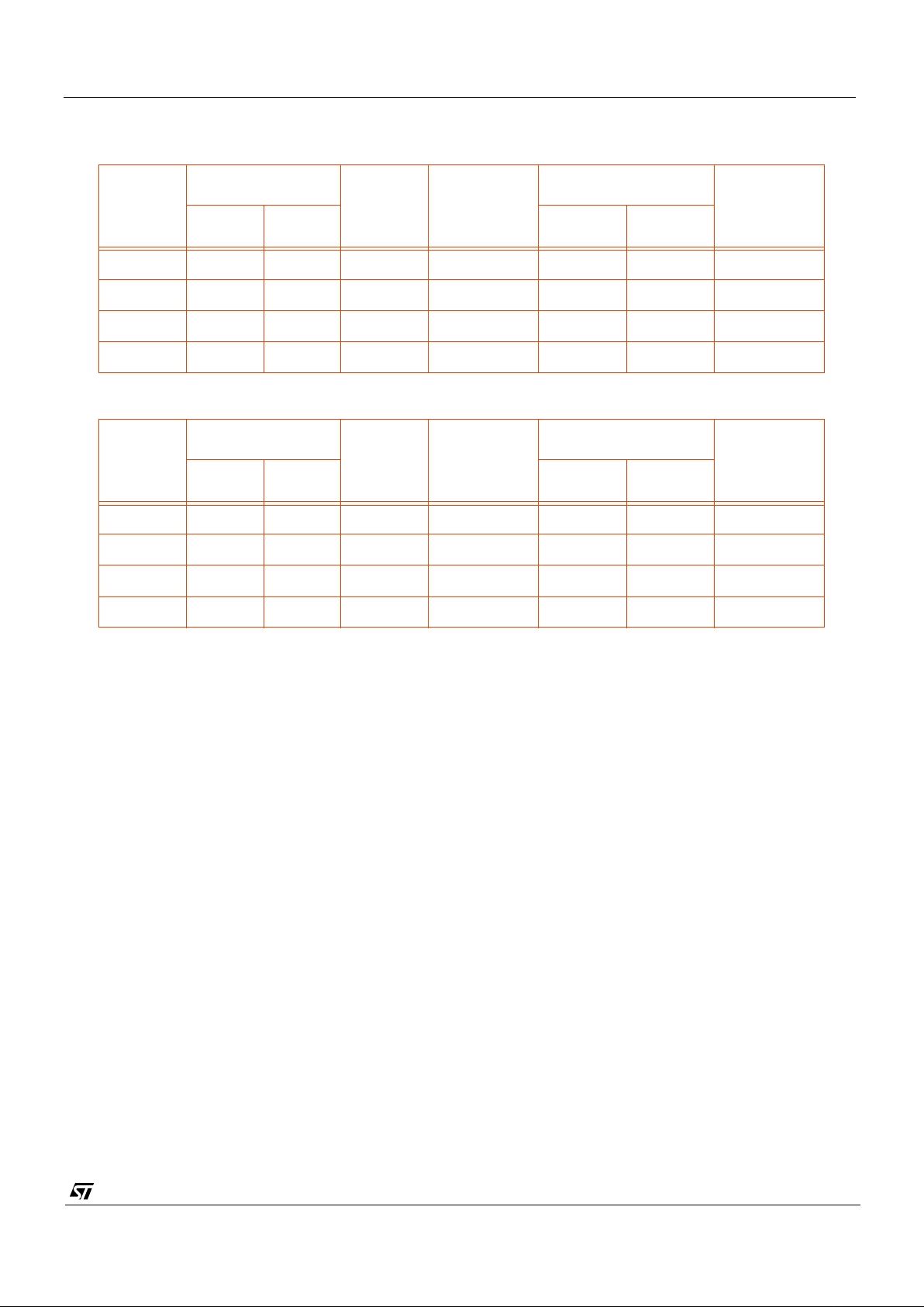
VV5404 & VV6404
CD5404-6404F-A
43/54
6.8 Synchronising 2 or More Cameras
A rising edge on the SIN pin re-synchronises the sensor’s internal video timing logic and clock generators to 5 pixels
before the end of the start of frame control sequence in line 0 (assuming the Setup2 register has been programmed
correctly with the value 30). By supplying an external timing signal to SIN, with a period equal to 2 frames (see Figure
28), 2 or more cameras can be synchronised together.
For proper synchronisation, the pixel counter register Setup2 must be written with 30, which will cause SIN to reset
the video timing to 5 pixel periods before the end of the start of frame control sequence. SIN is sampled internally by
the system clock, CKI. If all cameras are supplied with the same clock signal then the reset generated by SIN will
synchronise all the cameras to the same point in time. However, if the cameras being synchronised are running at
the same frequency but each camera has its own crystal, then there could be upto one system clock period of skew
between the cameras. This skew will vary over time due to the slight mis-matches between frequencies of the different
crystals.
.
CLKI
(MHz)
Clock Div Reg
Divisor
Pixel
Frequency
(MHz)
Frame rate (fps)
Comments
bit 1 bit 0 30 fps 25 fps
7.15909 0 0 2 3.57954 30.0 25.0 Default
7.15909 0 1 4 1.78977 15.0 12.5
7.15909 1 0 8 0.89489 7.50 6.25
7.15909 1 1 16 0.44744 3.75 3.125
Table 29 : Clock Divisor s for an exter na lly generated c lock signal.
CLKI
(MHz)
Clock Div Reg
Divisor
Pixel
Frequency
(MHz)
Frame rate (fps)
Comments
bit 1 bit 0 30 fps 25 fps
14.31818 0 0 2 7.15909 Not Valid
14.31818 0 1 4 3.57954 30.0 25.0
14.31818 1 0 8 1.78977 15.0 12.5
14.31818 1 1 16 0.89489 7.50 6.25
Table 30 : Clock Divisors fo r a 14.31 818 MHz Crystal
Page 44
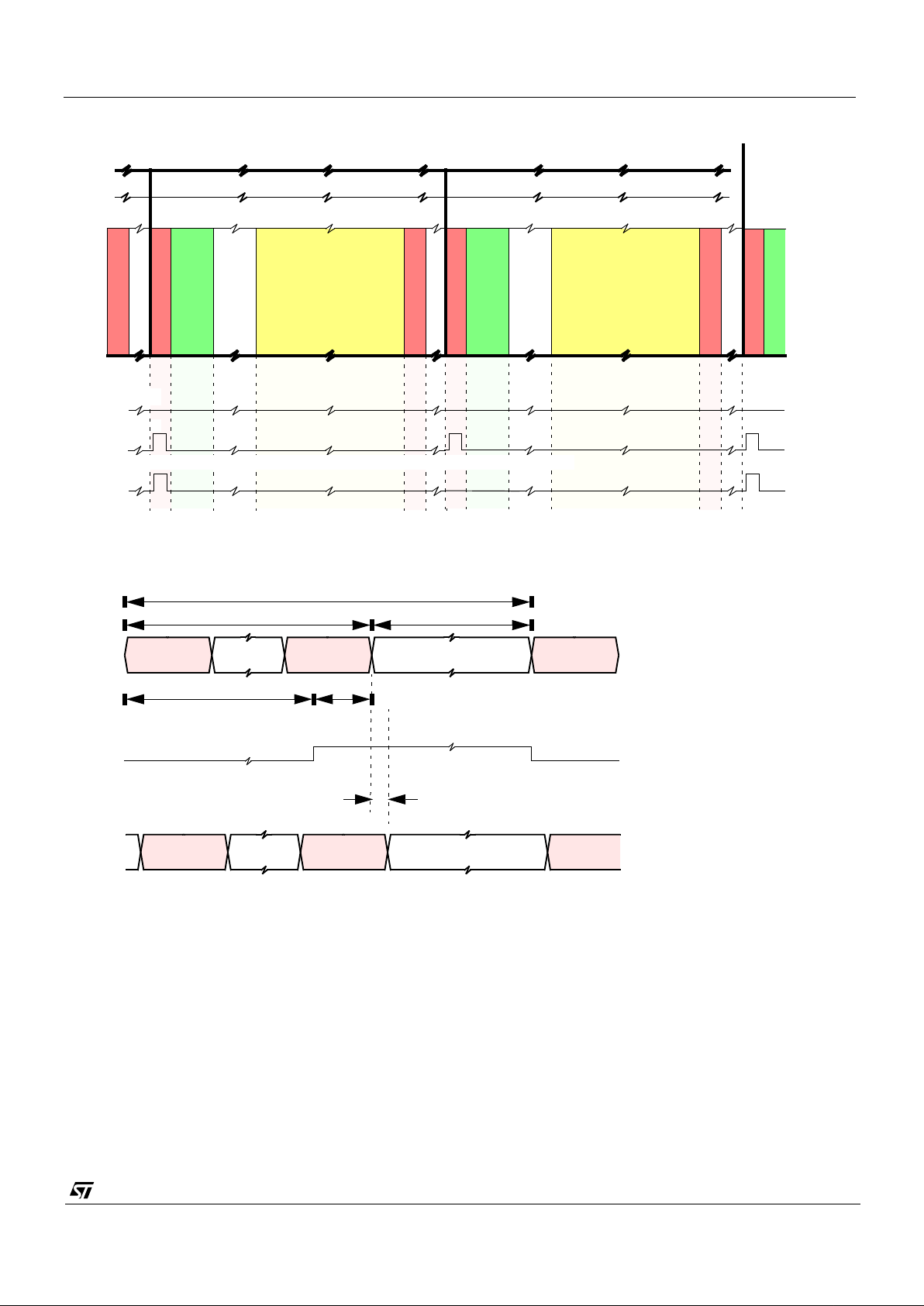
VV5404 & VV6404
CD5404-6404F-A
44/54
Figure 28 : Synchronisation Wa veforms
Start of Frame
Black Lines
Blanking Lines
Visible Lines
End of Frame
Blanking Lines
Blanking Lines
1st Frame
(ii) On
End of Frame
FST:
(ii) Off
Start of Frame
Black Lines
Blanking Lines
Visible Lines
End of Frame
Blanking Lines
2nd Frame
Start of Frame
SAVEAV EAV
Status Information
Synchronisation input (at SIN pin) from the master (e.g. video processor).
Line Period (393 Pixel Periods - 30 fps, 471 Pixel Periods - 25 fps)
356 Pixels
37 (115) Pixels
4 Pixels
33 (111) Pixels
SAVEAV EAV
Output of Slave 2 - Pixel Counter Reset Value = 30.
1 Pixel Period
Start of Frame Line Format:
Status Information
Frame Format:
(iii) Sync input at SI N ( if e xternal synchronisation required))
Page 45
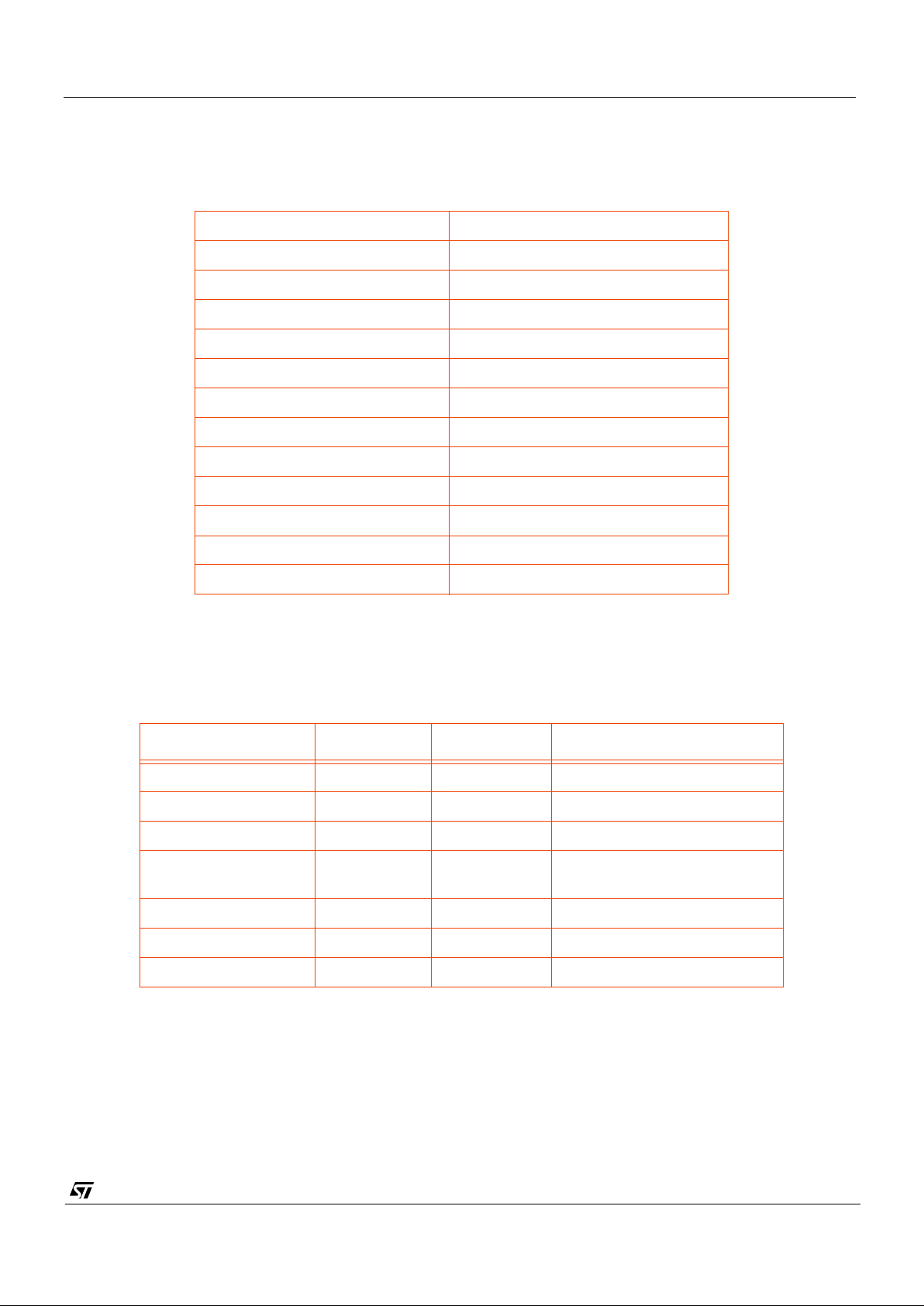
VV5404 & VV6404
CD5404-6404F-A
45/54
7. Detailed specificatio ns
7.1 General
* Contact ST Microelectr onics for information regarding increased temper ature range
7.2 DC characteristics
Image Format 356 x 292 pixels (CIF)
Pixel Size 12.0 x 11.0µm
Array Format CIF
Exposure control 25000:1 (performed by co-processor)
Sensor signal / Noise ratio 46dB
Minimum illumination 0.1 lux
Supply Voltage 5.0v D C +/-5%
Pac k age type 48LCC
Operating Temp. range 0
o
C - 40oC*
Serial interface frequency range 0-100kHz
Supply Voltage 5.0 V DC +/- 5%
Supply Current < 75 mA
Pac k age ty pe 48BGA
Table 31 : VV5407/6407 Specifications
Parameter Min. Max. Notes
V
IL
-0.5v 0.3 x V
DD
Guaranteed input low voltage
V
IH
0.7 x V
DD
VDD + 0.5v Guaranteed input high voltage
V
OL
0.4V At max IOL for pad type
V
OH
2.4v VDD - 0.5v IOH = 100µA
At max I
OH
for pad type
T
J
Junction Temp 0 deg C 100 deg C
Internal Pullup resistor 35kΩ 150k
Ω
Internal Pulldown resisto r 35k
Ω
150k
Ω
Table 32 : VV5407/6407 DC Characteristics
Page 46
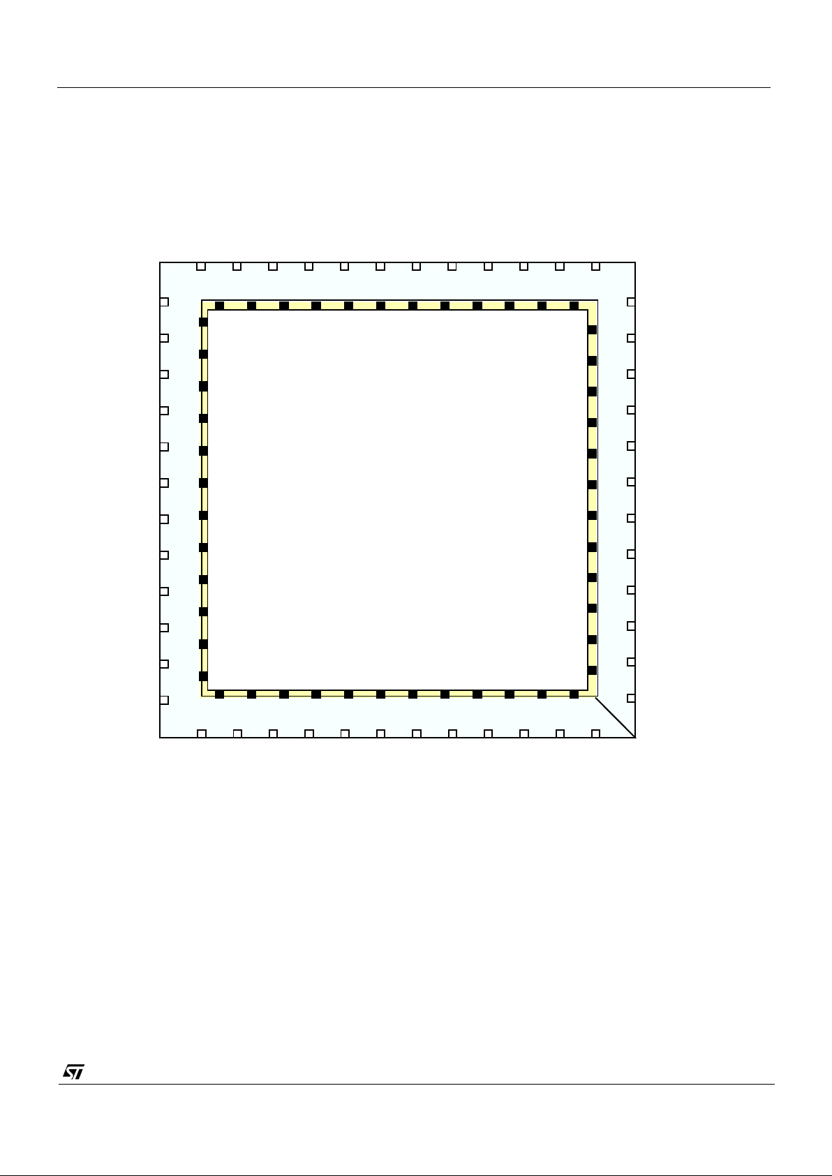
VV5404 & VV6404
CD5404-6404F-A
46/54
8. Physical
8.1 Pinout Diagram
(DNC) - Do not connect these pins
(*) - Paddle connections
CLKI
CLKO
D[0]
D[1]
VDD3
VSS3
DVSS/Dsub
VBLTW
VBG
VCDS
AVCC
AGND (*)
VVSS
ADCVSS (*)
ADCVDD
VDD1
VSS1
SIN
7
8
6
543214847464544
42
41
38
9
10
11
12
13
14
15
16
17
1920212223242526272829
32
33
34
35
36
37
D[2]
D[3]
FST
SDA
SCL
48 pin LCC
VCM / VREF2V5
AVSS
VBLOOM
ADCBot
40
39
18
30
31
43
(DNC)
AVDD
QCK
VVDD
OEB/SCI
RESETB
TopRef/ADCTop
HOLDPIX
VRT
VSS2
VDD2
(DNC)
DVDD
(DNC)
(DNC)
(DNC)
(DNC)
(DNC)
(DNC)
(DNC)
(DNC)
VV5/6404
Figure 29 : Pinout
Page 47
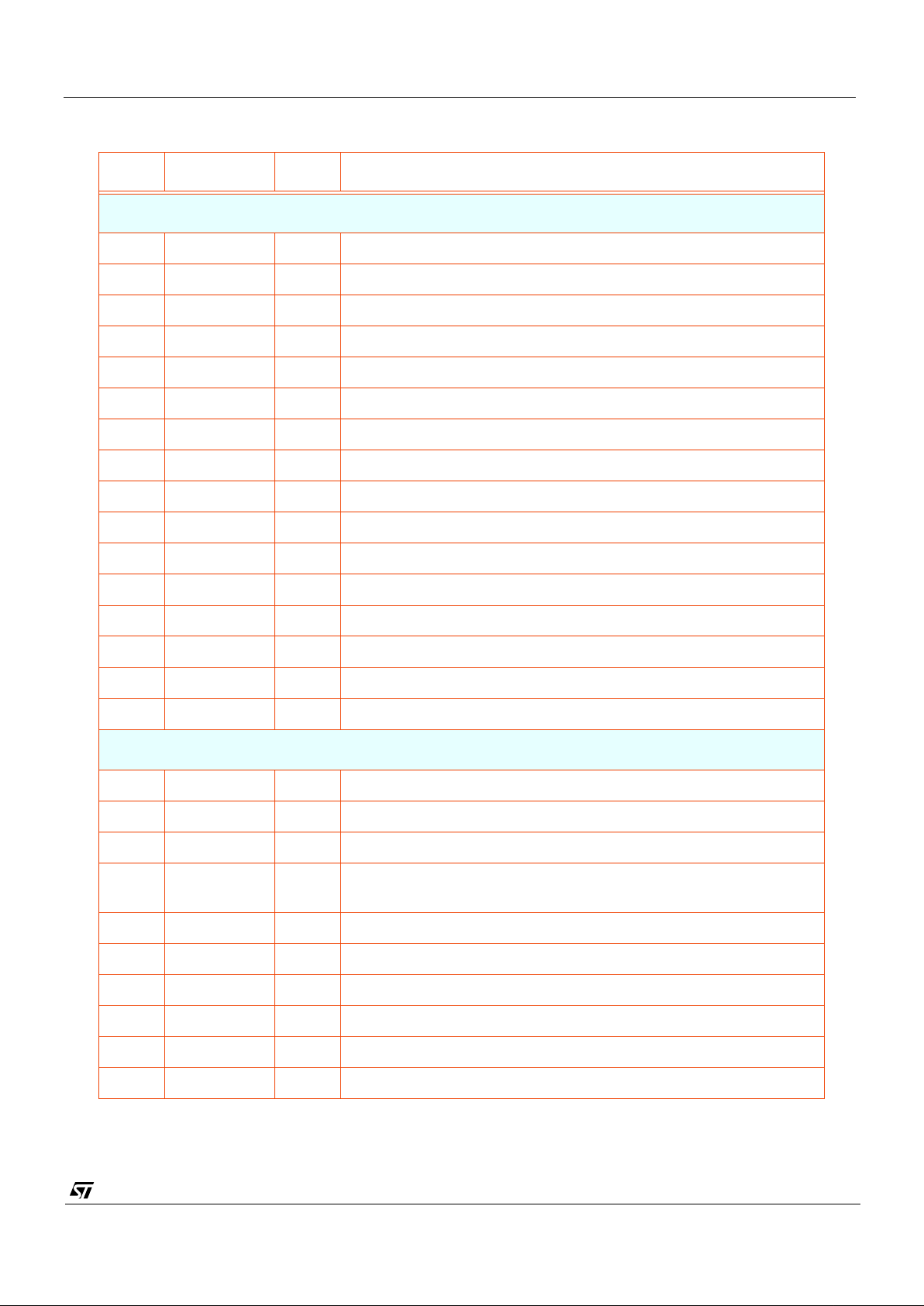
VV5404 & VV6404
CD5404-6404F-A
47/54
8.2 Signal Names
Pin Name Type Description
POWER SUPPLIES
1 AVCC PWR Core analogue power and reference supplies.
48 AGND GND Core analogue ground and reference supplies.
43 DVDD PWR Core digital power.
44 DVSS/Dsub GND Core digital ground.
6 AVDD PWR Output stage power.
5 AVSS GND Output stage ground.
7 VVDD PWR Analogue output buffer power.
9 VVSS GND Analogue output buffer ground.
14 ADCVDD PWR ADC power.
10 ADCVSS GND ADC ground.
19 VDD1 PWR Digital padring & logic power.
30 VDD2 PWR Digital padring & logic power.
36 VDD3 PWR Digital padring & logic power.
20 VSS1 GND Digital padring & logic ground.
29 VSS2 GND Digital padring & logic ground.
37 VSS3 GND Digital padring & logic ground.
ANALOGUE SIGNALS
45 VBLOOM OA Anti-blooming pixel reset voltage
46 VBLTW OA Bitline test white level reference
47 VBG OA Internally generated bandgap reference voltage 1.22V
2VCM/
VREF2V5
OA Common-mode input for OSA and Internally generated 2.5 V
reference voltage.
3 VRT IA Pixel reset voltage
4 VCDSH IA
8 AV O OA Analogue Test output
11 ADCbot IA Bottom voltage reference for ADC
12 HoldPix IA Not for Customer use
13 TopRef OA Internally generally top voltage reference for ADC
Page 48
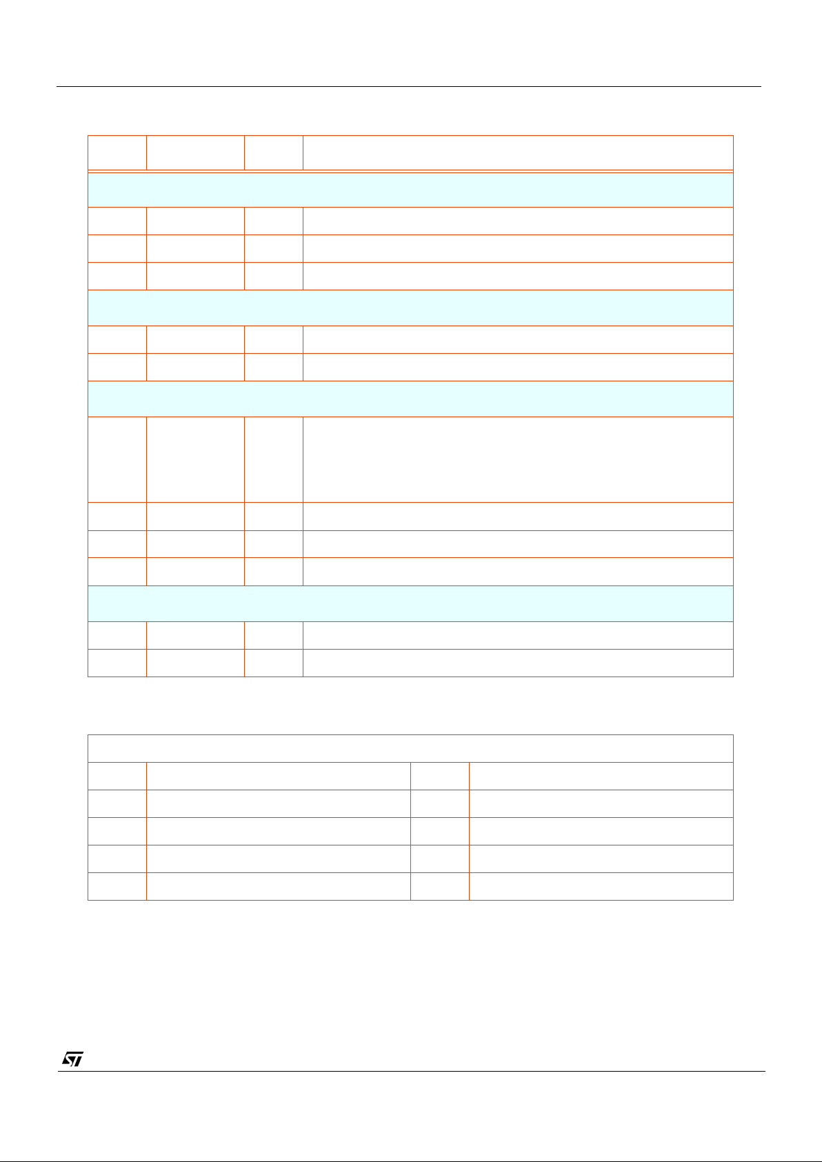
VV5404 & VV6404
CD5404-6404F-A
48/54
Pin Name Type Description
DIGITAL CONTROL SIGNALS
18 SCE I D
↓
Test Pin
15 SIN ID
↓
Frame timing reset (soft reset).
16 RESETB ID
↑
System Reset. Active Low.
SERIAL INTERFACE
42 SCL ID
↑
Serial bus clock (input only).
41 SDA B I
↑
Serial bus data (bidirectional, open drain).
DIGITAL VIDEO INTERFACE
39
38
35
34
D[3]
D[2]
D[1]
D[0]]
ODT Tristateable 4-wire output data bus. D[3] is the most significant bit.
33 QCK ODT Tristateable data qualification clock.
40 FST ODT Tristateable Frame sta rt si gna l.
17 OEB ID
↓
Digital output (trist ate) enable.
SYSTEM CLOCKS
31 CLKI ID Oscillator input.
32 CLKO OD Oscillator output.
Key
A Analogue Input D Digital Input
OA Analogue Output ID
↑
Digital input with internal pull-up
BI Bidirectional ID
↓
Digital input with internal pull-down
BI
↑
Bidirectional with internal pull-up OD Digital Output
BI
↓
Bidirectional with internal pull-down ODT Tristateable Digital Output
Page 49
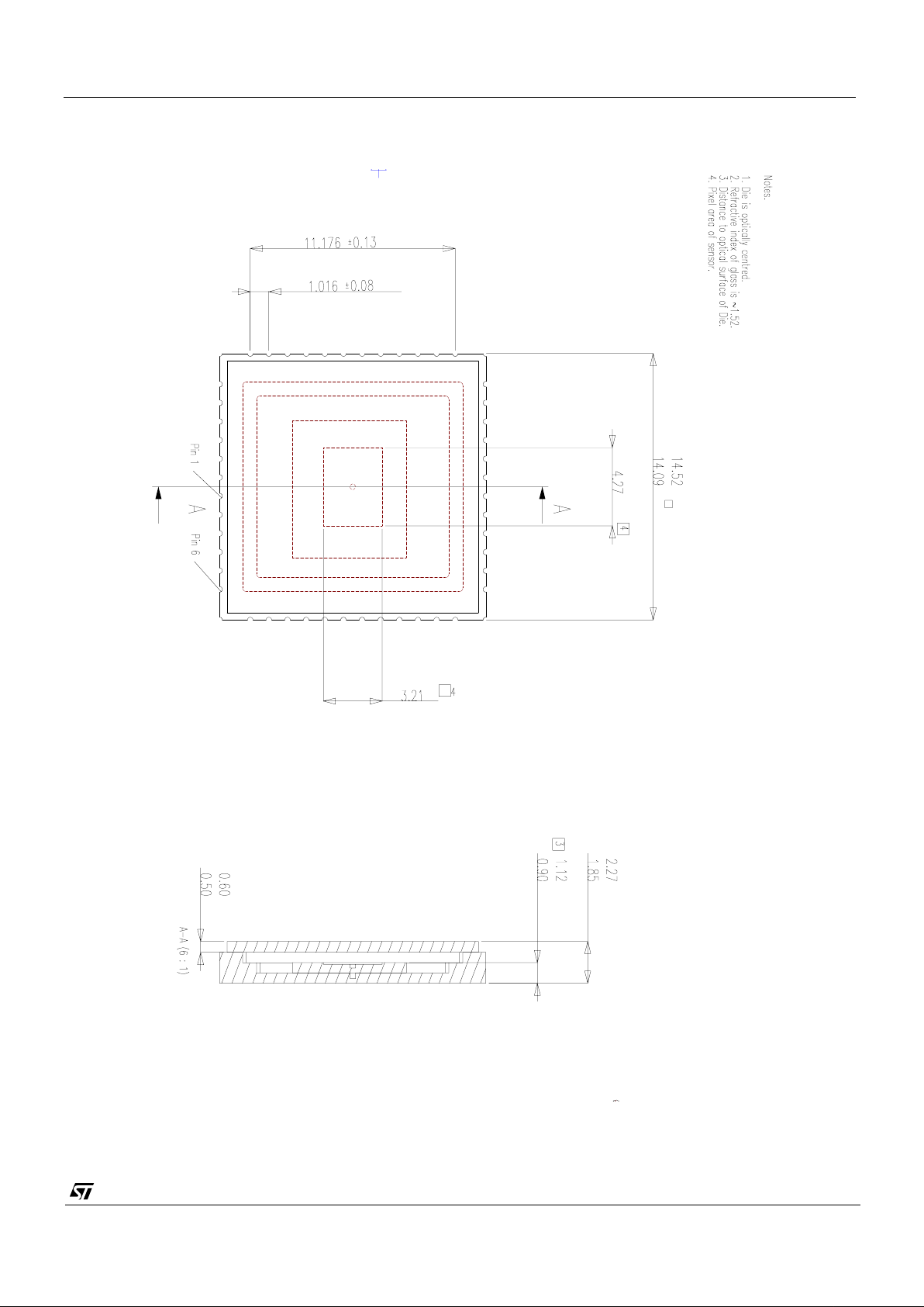
VV5404 & VV6404
CD5404-6404F-A
49/54
8.3 48LCC Mechanical Dimensions
Page 50
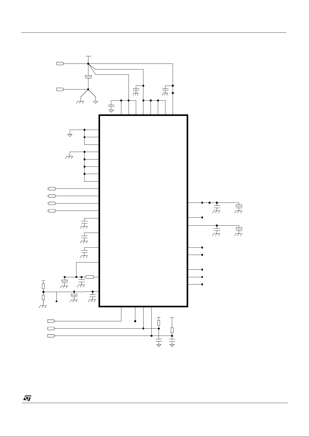
VV5404 & VV6404
CD5404-6404F-A
50/54
8.4 VV6404 Sensor Support Circuit Schematic Diagram
8.5 Sensor Support Circuit Component List
C1
C4
IC1
16
36
3231
1
45
3
6
47
46
15
19
(48 pin LCC)
43 7
34
38
35
39
4241
12
13
11
20
29
37
44
5
2
C2
48
SCL
CLKI
SDA
D[3]
D[1]
D[2]
D[0]
D[3]
D[2]
D[1]
D[0]
ADCVDD
ADCVSS
SCL
SDA
RESETB
VCM / VREF2V5
VBLOOM
VRT
VBLTW
VVSS
VVDD
VCDSH
VBG
ADCbot
Holdpix
ADCtop/TopRef
QCK
FST
OEB
SIN
VSS1
VSS2
VSS3
VDD3
VDD2
VDD1
DVDD
DVSS
AVSS
AGND
4
33
40
CLKI
CLKO
C15
C5
17
10
9
C13
C14 C16
AVCC
AVDD
30 14
C4
C3
C8
C6
VV5/6404
R3
DVDD/AVDD
R4
R5
C11
C12
R2
R1
TP1
C10
AVDD
DVDD
C7C9
+5v DC
0v
DGNDAGND
Page 51
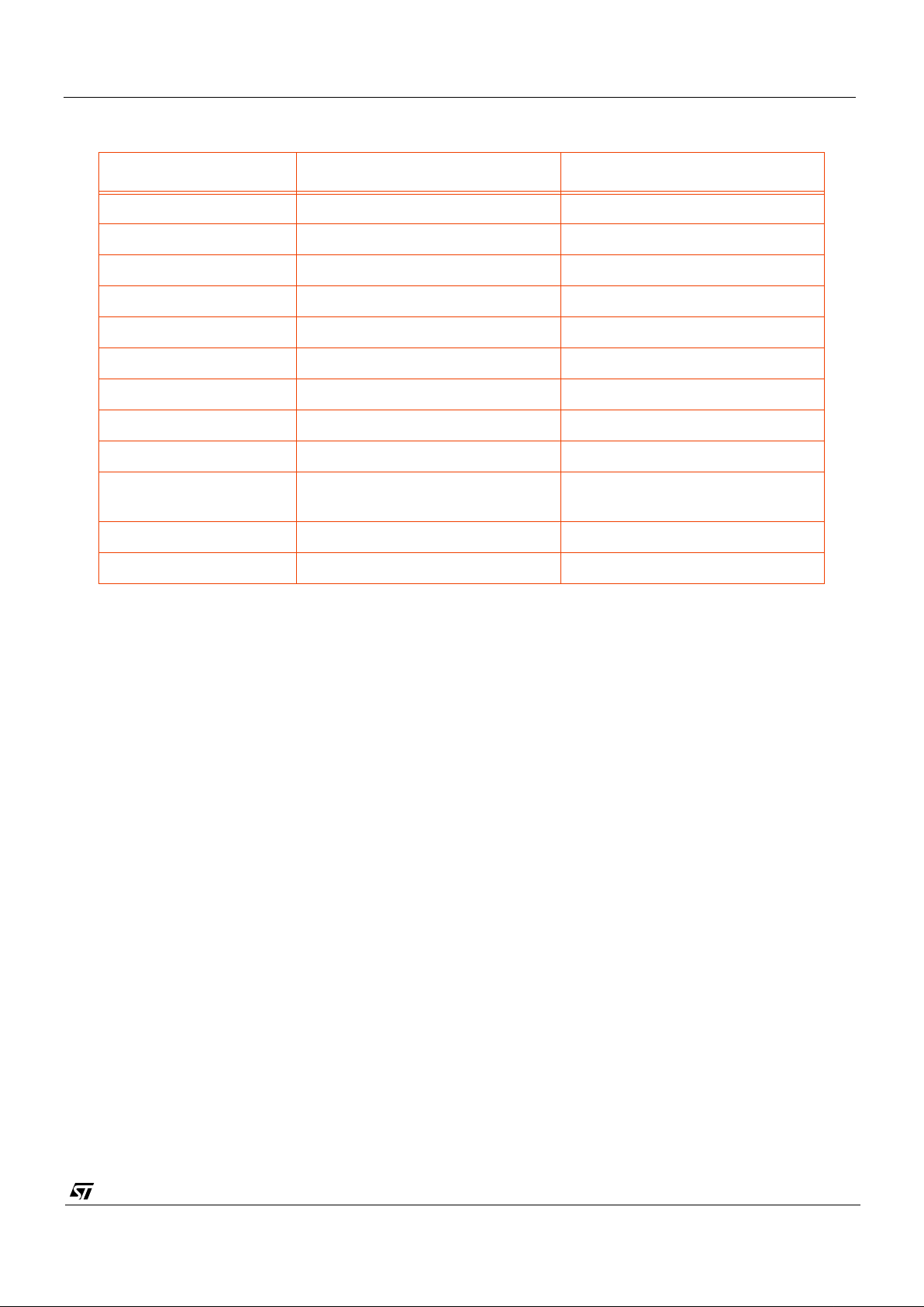
VV5404 & VV6404
CD5404-6404F-A
51/54
Notes:
1. Use surface mount component s through out .
2. All ceramic capacitors are type COG.
3. Keep nodes Supply and Ground pins low impedance and independent.
4. Keep circuit components close to chip pins (especially de-coupling capacitors).
5. EMC precautions will be required on D[3:0] if driving a longer cable.
Component Part No. / Provisional Value Rating / Notes
IC1 VV6404A VVL camera chip (48 pin LCC)
C1 10.0 µF6V tant.
C2-C3, C4-C6, C7-C8 0.1 µF
C9-C10 10.0 µF 6V tant.
C11-C12 220pF(*) For 3m cable length
C13-C14 0.1 µF
C15 4.7 µF 6V tant
C16 10.0 µF 6V tant
TDB
R1-R2 Voltage divider such that TP1 =
3.2v
R3 33Ω
R4-R5 2k2
Ω(∗)
For 3m cable length
Table 33 : PCB Component List
Page 52
VV5404 & VV6404
CD5404-6404F-A
52/54
9. Ordering Information
Part Number Description Defect specification
VV5404C001 CIF resolution monochrome Digital
CMOS Image Sensor, 48 pin LCC
package
zero defects
VV6404C001 CIF resolution Colour Digital CMOS
Image Sensor, 48 pin LCC package
zero defects
VV6404C001-B2 CIF resolution Colour Digital CMOS
Image Sensor, 48 pin LCC package
up to 36 defects
for use when pixel
defect correction is
implemented
STV5404E-001 Evaluation Kit for VV5404 sensor N/A
STV6404E-001 Evaluation Kit for VV6404 sensor N/A
Page 53

VV5404 & VV6404
CD5404-6404F-A
53/54
Page 54

VV5404 & VV6404
CD5404-6404F-A
54/54
Information furnished is believed to be accurate and reliable. However, STMicroelectronics assumes no responsibility for the
consequences of use of such information nor for any infringement of patents or other rights of third parties which may result from
its use. No license is granted by implication or otherwise under any patent or patent rights of STMicroelectronics. Specifications
mentioned in this publication are subject to change without notice. This publication supersedes and replaces all information
previously supplied. STMicroelectronics products are not authorized for use as critical components in life support devices or
systems without express written approval of STMicroelectronics
The ST logo is a registered trad emark of STMicroelectronics
© 1999 STMicroelectronics - All Rights Reserved
.
VLSI VISION
L
IMITED
A company of the ST Microelectronics Group
®
www.vvl.co.uk
www.st.com
 Loading...