

Page 1
© 2000 IXYS All rights reserved
1 - 2
I
dA VM
= 82 A
V
RRM
= 800-1800 V
V
RSM
V
RRM
Type
VV
900 800 VUO 80-08NO1
1300 1200 VUO 80-12NO1
1500 1400 VUO 80-14NO1
1700 1600 VUO 80-16NO1
1900 1800 VUO 80-18NO1
Symbol Test Conditions Characteristic Values
I
R
VR= V
RRM
TVJ = 25°C £ 0.3 mA
VR= V
RRM
TVJ = T
VJM
£ 6mA
V
F
IF= 80 A; TVJ = 25°C £ 1.5 V
V
T0
For power-loss calculations only 0.8 V
r
T
7.5 mW
R
thJH
per diode, 120° rect. 1.42 K/W
per module, 120° rect. 0.24 K/W
d
S
Creeping distance on surface 12.7 mm
d
A
Creepage distance in air 9.4 mm
a Max. allowable acceleration 50 m/s
2
Symbol Test Conditions Maximum Ratings
I
dAV
TK = 90°C, module 82 A
I
dAVM
module 82 A
I
FSM
TVJ = 45°C; t = 10 ms (50 Hz), sine 600 A
VR = 0 t = 8.3 ms (60 Hz), sine 640 A
T
VJ
= T
VJM
t = 10 ms (50 Hz), sine 520 A
VR = 0 t = 8.3 ms (60 Hz), sine 555 A
I
2
t TVJ = 45°C t = 10 ms (50 Hz), sine 1800 A2s
VR = 0 t = 8.3 ms (60 Hz), sine 1720 A2s
T
VJ
= T
VJM
t = 10 ms (50 Hz), sine 1350 A2s
VR = 0 t = 8.3 ms (60 Hz), sine 1295 A2s
T
VJ
-40...+150 °C
T
VJM
150 °C
T
stg
-40...+130 °C
V
ISOL
50/60 Hz, RMS t = 1 min 3000 V~
I
ISOL
£ 1 mA t = 1 s 3600 V~
M
d
Mounting torque (M5) 2 - 2.5 Nm
(10-32UNF) 18-22 lb.in.
Weight typ. 35 g
Features
●
Package with DCB ceramic base plate
●
Isolation voltage 3600 V~
●
Planar passivated chips
●
Blocking voltage up to 1800 V
●
Low forward voltage drop
●
Leads suitable for PC board soldering
●
UL registered E72873
Applications
●
Supplies for DC power equipment
●
Input rectifiers for PWM inverter
●
Battery DC power supplies
●
Field supply for DC motors
Advantages
●
Easy to mount with two screws
●
Space and weight savings
●
Improved temperature and power
cycling
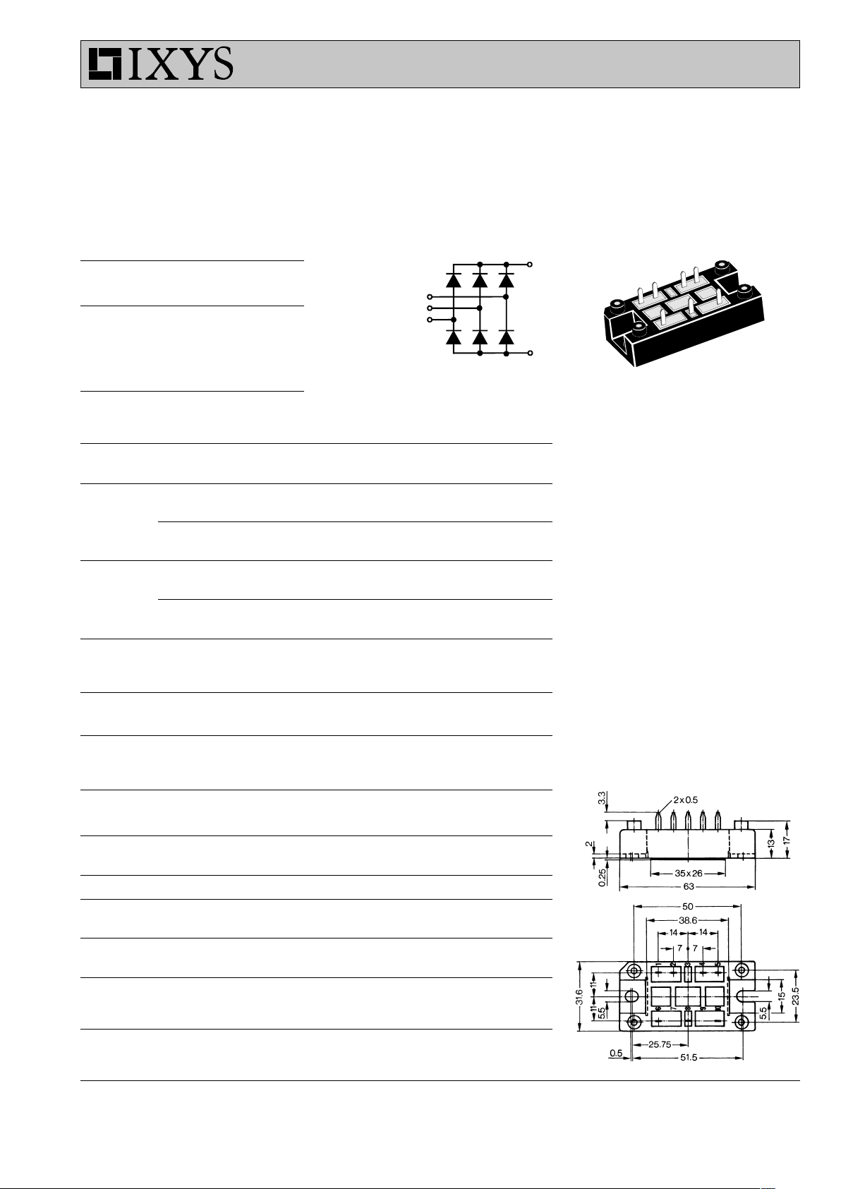
Dimensions in mm (1 mm = 0.0394")
Data according to IEC 60747 and refer to a single diode unless otherwise stated.
IXYS reserves the right to change limits, test conditions and dimensions.
VUO 80
Three Phase
Rectifier Bridge
934
1
2
4
5
6
10
8
10
8
6
4/5
1/2
Page 2
© 2000 IXYS All rights reserved
2 - 2
VUO 80
0.001 0.01 0.1 1
0
100
200
300
400
500
23456789110
10
2
10
3
10
4
0.00.51.01.52.0
0
10
20
30
40
50
60
70
80
0 1020304050607080
0
50
100
150
200
0 20 40 60 80 100 120 140
0.001 0.01 0.1 1 10
0.0
0.2
0.4
0.6
0.8
1.0
1.2
1.4
1.6
I2t
I
FSM
I
F
A
V
F
t
s
t
ms
P
tot
W
I
d(AV)M
A
T
amb
t
s
K/W
A
2
s
0 20 40 60 80 100 120 140
0
20
40
60
80
100
I
d(AV)M
T
H
A
V
A
°C °C
VUO 80
T
VJ
= 45°C
50Hz, 80% V
RRM
VR = 0 V
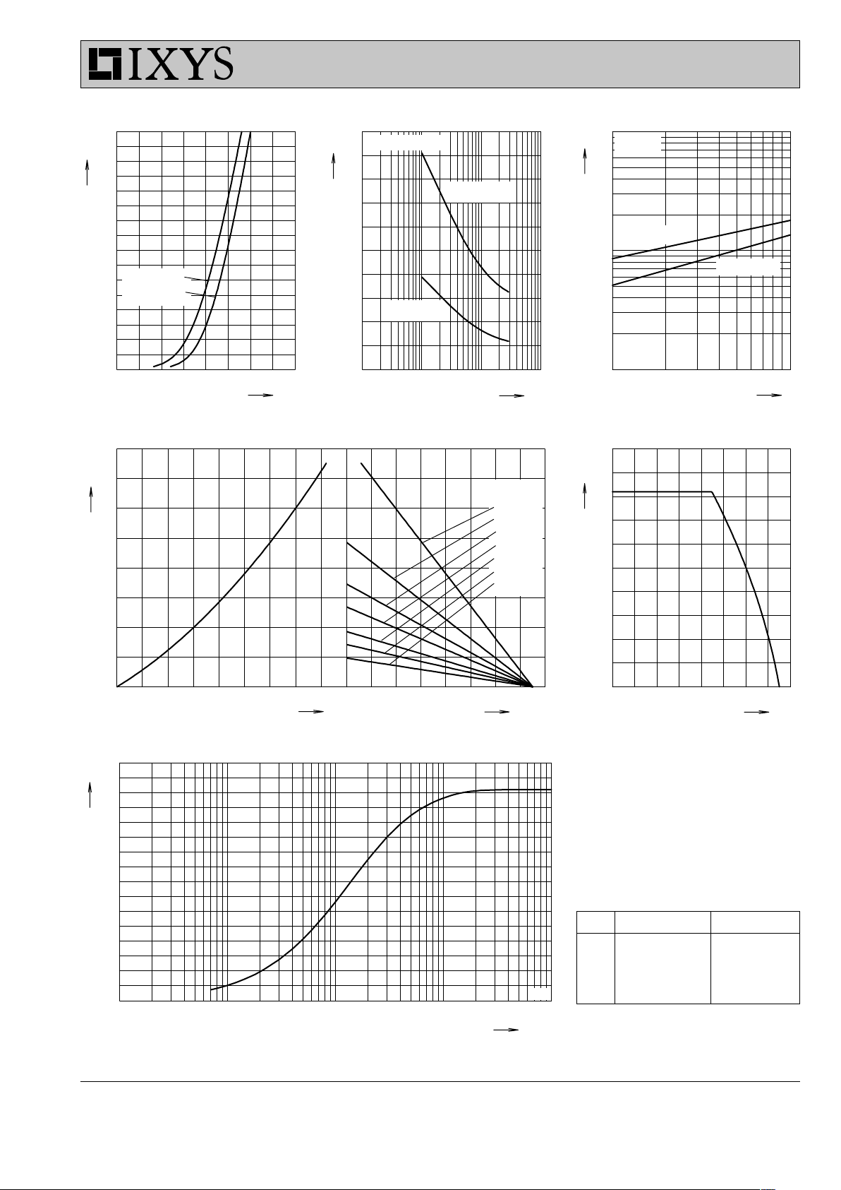
Fig. 1 Forward current versus voltage
drop per diode
Fig. 2 Surge overload current Fig. 3 I2t versus time per diode
Fig. 4 Power dissipation versus direct output current and ambient temperature Fig. 5 Max. forward current versus
heatsink temperature
Fig. 6 Transient thermal impedance junction to heatsink
Constants for Z
thJH
calculation:
iR
thi
(K/W) ti (s)
1 0.005 0.01
2 0.21 0.05
3 0.795 0.14
4 0.41 0.5
R
thHA
:
0.5 K/W
1.0 K/W
1.5K/W
2.0 K/W
3.0 K/W
4.0 K/W
6.0 K/W
T
VJ
= 150°C
T
VJ
= 45°C
TVJ=150°C
TVJ= 25°C
T
VJ
= 150°C
Z
thJH
 Loading...