

Page 1
www.vishay.com
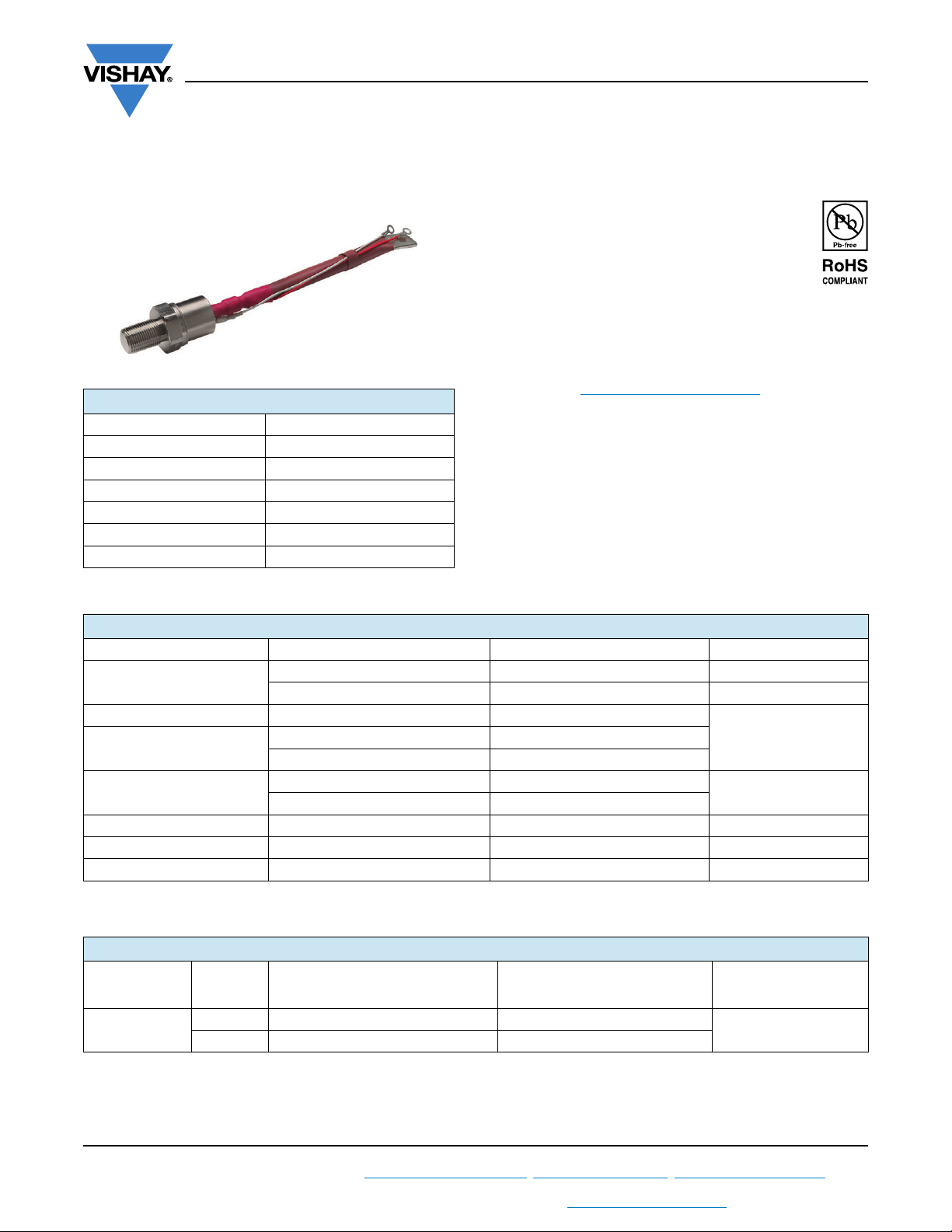
TO-209AB (TO-93)
PRODUCT SUMMARY
I
T(AV)
V
DRM/VRRM
V
TM
I
GT
T
J
Package TO-209AB (TO-93)
Diode variation Single SCR
Phase Control Thyristors
(Stud Version), 280 A
FEATURES
• Center amplifying gate
• International standard case TO-209AB (TO-93)
• Hermetic metal case with glass-metal seal
insulator
• Compression bonded encapsulation for heavy duty
operations such as severe thermal cycling
• Designed and qualified for industrial level
• Material categorization: For definitions of compliance
please see www.vishay.com/doc?99912
280 A
400 V, 600 V
1.28 V
150 mA
-40 °C to 125 °C
TYPICAL APPLICATIONS
• DC motor controls
• Controlled DC power supplies
• AC controllers
VS-ST280S Series
Vishay Semiconductors
MAJOR RATINGS AND CHARACTERISTICS
PARAMETER TEST CONDITIONS VALUES UNITS
I
T(AV)
I
T(RMS)
I
TSM
2
I
t
V
DRM/VRRM
t
q
T
J
T
C
50 Hz 7850
60 Hz 8220
50 Hz 308
60 Hz 281
Typical 100 μs
280 A
85 °C
440
400/600 V
-40 to 125 °C
ELECTRICAL SPECIFICATIONS
VOLTAGE RATINGS
TYPE NUMBER
VS-ST280S
V
VOLTAGE
CODE
04 400 500
06 600 700
DRM/VRRM
PEAK AND OFF-STATE VOLTAGE
, MAXIMUM REPETITIVE
NON-REPETITIVE PEAK VOLTAGE
V
V
, MAXIMUM
RSM
I
DRM/IRRM
T
= TJ MAXIMUM mA
V
J
A
kA2s
MAXIMUM AT
30
Revision: 11-Mar-14
For technical questions within your region: [email protected]
THIS DOCUMENT IS SUBJECT TO CHANGE WITHOUT NOTICE. THE PRODUCTS DESCRIBED HEREIN AND THIS DOCUMENT
ARE SUBJECT TO SPECIFIC DISCLAIMERS, SET FORTH AT www.vishay.com/doc?91000
1
Document Number: 94402
Page 2
VS-ST280S Series
www.vishay.com
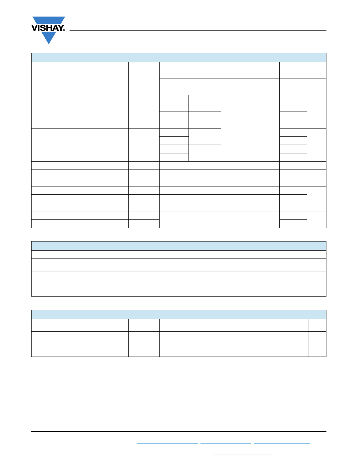
ABSOLUTE MAXIMUM RATINGS
PARAMETER SYMBOL TEST CONDITIONS VALUES UNITS
Maximum average on-state current
at case temperature
Maximum RMS on-state current I
T(RMS)
Maximum peak, one-cycle
non-repetitive surge current
Maximum I
Maximum I
2
t for fusing I2t
2
t for fusing I2t t = 0.1 to 10 ms, no voltage reapplied 3100 kA2s
Low level value of threshold voltage V
High level value of threshold voltage V
Low level value of on-state slope resistance r
High level value of on-state slope resistance r
Maximum on-state voltage V
Maximum holding current I
Maximum (typical) latching current I
I
T(AV)
I
TSM
T(TO)1
T(TO)2
t1
t2
TM
H
L
180° conduction, half sine wave 280 A
DC at 75 °C case temperature 440
t = 10 ms
t = 8.3 ms 8220
t = 10 ms
t = 8.3 ms 6900
t = 10 ms
t = 8.3 ms 220
t = 10 ms
t = 8.3 ms 200
(16.7 % x x I
(I > x I
(16.7 % x x I
(I > x I
No voltage
reapplied
100 % V
reapplied
RRM
No voltage
reapplied
100 % V
reapplied
), TJ = TJ maximum 0.88
T(AV)
), TJ = TJ maximum 0.47
T(AV)
T(AV)
T(AV)
RRM
< I < x I
< I < x I
Ipk = 880 A, TJ = TJ maximum, tp = 10 ms sine pulse 1.28 V
TJ = 25 °C, anode supply 12 V resistive load
Vishay Semiconductors
Sinusoidal half wave,
initial T
= TJ maximum
J
), TJ = TJ maximum 0.84
T(AV)
), TJ = TJ maximum 0.50
T(AV)
1000 (300)
85 °C
7850
6600
310
218
600
A
kA2s
V
m
mA
SWITCHING
PARAMETER SYMBOL TEST CONDITIONS VALUES UNITS
Maximum non-repetitive rate of rise
of turned-on current
Typical delay time t
Typical turn-off time t
dI/dt
d
q
Gate drive 20 V, 20 , t
T
= TJ maximum, anode voltage 80 % V
J
Gate current 1 A, dIg/dt = 1 A/μs
V
= 0.67 % V
d
DRM
ITM = 300 A, TJ = TJ maximum, dI/dt = 20 A/μs,
V
= 50 V, dV/dt = 20 V/μs, gate 0 V 100 , tp = 500 μs
R
1 μs
r
, TJ = 25 °C
DRM
1000 A/μs
1.0
μs
100
BLOCKING
PARAMETER SYMBOL TEST CONDITIONS VALUES
Maximum critical rate of rise
of off-state voltage
Maximum peak reverse and
off-state leakage current
dV/dt T
I
RRM,
I
DRM
= TJ maximum linear to 80 % rated V
J
TJ = TJ maximum, rated V
DRM/VRRM
DRM
500 V/μs
applied 30 mA
UNIT
S
Revision: 11-Mar-14
For technical questions within your region: [email protected]
THIS DOCUMENT IS SUBJECT TO CHANGE WITHOUT NOTICE. THE PRODUCTS DESCRIBED HEREIN AND THIS DOCUMENT
ARE SUBJECT TO SPECIFIC DISCLAIMERS, SET FORTH AT www.vishay.com/doc?91000
2
Document Number: 94402
Page 3
VS-ST280S Series
www.vishay.com
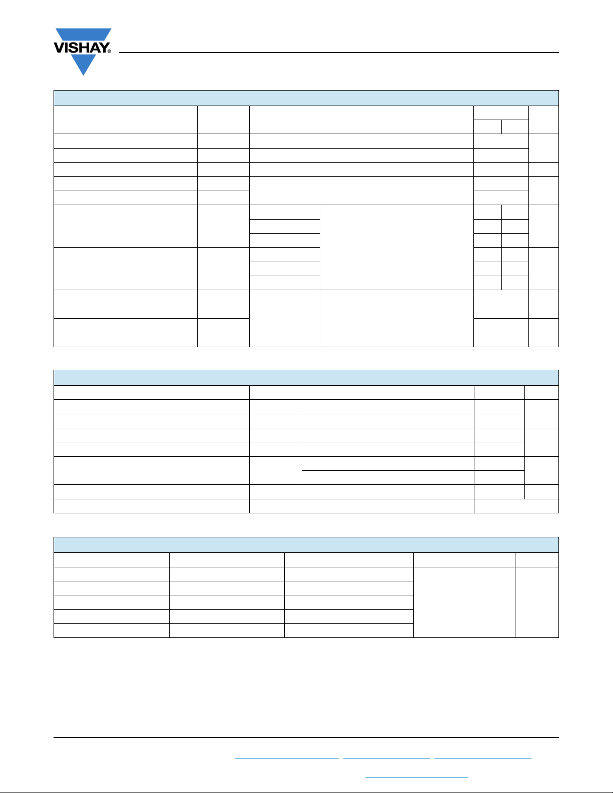
TRIGGERING
PARAMETER SYMBOL TEST CONDITIONS
Maximum peak gate power P
Maximum average gate power P
Maximum peak positive gate current I
Maximum peak positive gate voltage + V
Maximum peak negative gate voltage - V
DC gate current required to trigger I
DC gate voltage required to trigger V
GM
G(AV)
GM
GM
GM
GT
GT
TJ = TJ maximum, tp 5 ms 10.0
TJ = TJ maximum, f = 50 Hz, d% = 50 2.0
TJ = TJ maximum, tp 5 ms 3.0 A
TJ = TJ maximum, tp 5 ms
TJ = - 40 °C
= 25 °C 90 150
J
= 125 °C 40 -
T
J
TJ = - 40 °C 2.9 -
= 25 °C 1.8 3.0
J
T
= 125 °C 1.2 -
J
Maximum required gate trigger/current/
voltage are the lowest value which will
trigger all units 12 V anode to cathode
applied
Vishay Semiconductors
VALUES
TYP. MAX.
180 -
20
5.0
UNIT
S
W
V
mAT
VT
DC gate current not to trigger I
DC gate voltage not to trigger V
GD
GD
TJ = TJ maximum
Maximum gate current/voltage not to
trigger is the maximum value which will
not trigger any unit with rated V
anode to cathode applied
DRM
10 mA
0.25 V
THERMAL AND MECHANICAL SPECIFICATIONS
PARAMETER SYMBOL TEST CONDITIONS VALUES UNITS
Maximum operating junction temperature range T
Maximum storage temperature range T
Maximum thermal resistance, junction to case R
Maximum thermal resistance, case to heatsink R
Mounting torque, ± 10 %
J
Stg
thJC
thCS
DC operation 0.105
Mounting surface, smooth, flat and greased 0.04
Non-lubricated threads 31 (275)
Lubricated threads 24.5 (210)
Approximate weight 280 g
Case style See dimensions - link at the end of datasheet TO-209AB (TO-93)
R
CONDUCTION
thJC
CONDUCTION ANGLE SINUSOIDAL CONDUCTION RECTANGULAR CONDUCTION TEST CONDITIONS UNITS
180° 0.016 0.012
120° 0.019 0.020
T
90° 0.025 0.027
= TJ maximum K/W
J
60° 0.036 0.037
30° 0.060 0.060
Note
• The table above shows the increment of thermal resistance R
when devices operate at different conduction angles than DC
thJC
-40 to 125
-40 to 150
(lbf · in)
°C
K/W
N · m
Revision: 11-Mar-14
For technical questions within your region: [email protected]
THIS DOCUMENT IS SUBJECT TO CHANGE WITHOUT NOTICE. THE PRODUCTS DESCRIBED HEREIN AND THIS DOCUMENT
ARE SUBJECT TO SPECIFIC DISCLAIMERS, SET FORTH AT www.vishay.com/doc?91000
3
Document Number: 94402
Page 4

VS-ST280S Series
80
90
100
110
120
130
0 50 100 150 200 250 300
Maximum Allowable Ca se Temp erature (°C)
30°
60°
90°
120°
180°
Average On-state Current (A)
Conduction Angle
ST2 80 S Se r i e s
R (DC) = 0.105 K/ W
thJC
70
80
90
100
110
120
130
0 50 100 150 200 250 300 350 400 450
DC
30°
60°
90°
120°
180°
Average On-state Current (A)
Maximum Allowab le Case Temp erature (°C)
Conduc tion Period
ST2 80 S Se r ie s
R ( DC) = 0.105 K/ W
thJC
25 50 75 100 125
Maximum Allowable Ambient Temperature (°C)
R
=
0
.
1
K
/
W
D
e
l
t
a
R
0
.
1
6
K
/
W
0
.
2
K
/
W
0
.
2
5
K
/
W
0
.
3
K
/
W
0
.
4
K
/
W
0
.
6
K
/
W
0
.
8
K
/
W
1
.
2
K
/
W
t
h
S
A
0
50
100
150
200
250
300
350
0
50 100 150 200 250 300
180°
120°
90°
60°
30°
RM S Lim it
Conduc tion Angle
Maximum Average On-state Power Loss (W)
Avera g e On -st at e C urre n t ( A)
ST280S Se ries
T = 125°C
J
www.vishay.com
Fig. 1 - Current Ratings Characteristics Fig. 2 - Current Ratings Characteristics
Vishay Semiconductors
Revision: 11-Mar-14
For technical questions within your region: [email protected]
THIS DOCUMENT IS SUBJECT TO CHANGE WITHOUT NOTICE. THE PRODUCTS DESCRIBED HEREIN AND THIS DOCUMENT
Fig. 3 - On-State Power Loss Characteristics
500
450
400
350
300
250
200
150
100
50
0
Maximum Average On-state Power Loss (W)
ARE SUBJECT TO SPECIFIC DISCLAIMERS, SET FORTH AT www.vishay.com/doc?91000
DC
180°
120°
90°
60°
30°
RM S Lim i t
0 50 100150200250300350400450
Average On-state Current (A)
Conduction Period
ST280S Series
T = 12 5° C
J
25 50 75 100 125
Maximum Allowab le Ambient Temp erature (°C)
Fig. 4 - On-State Power Loss Characteristics
4
0
0
0
0
0
.
0
.
4
0
.
1
R
0
.
0
t
6
h
S
K
A
/
.
0
W
8
K
/
W
.
1
2
K
/
.
1
6
K
/
.
2
K
/
W
3
K
/
W
K
/
W
6
K
/
W
K
/
W
=
0
.
0
3
K
/
W
W
W
D
e
l
t
a
R
Document Number: 94402
Page 5

VS-ST280S Series
3000
3500
4000
4500
5000
5500
6000
6500
7000
110100
Numb er Of Eq ua l Amp litud e Half Cy c le Current Pulses (N)
Pea k Half Sine Wa ve On-sta te Curren t (A)
ST2 80 S Se r i e s
Initia l T = 125°C
@ 60 Hz 0. 0083 s
@ 50 Hz 0. 0100 s
J
At Any Ra te d Load Co ndition And With
Rated V Applied Following Surge.
RRM
0.001
0.01
0.1
1
0.001 0. 01 0.1 1 10
Sq u a r e W a v e P u l se D u r a t i o n ( s)
thJC
Transient Th ermal Imped anc e Z (K/W)
Steady State Value
R = 0.105 K/ W
(DC Operation)
ST2 8 0 S Se r i e s
thJC
www.vishay.com
7000
At Any Ra te d Load C ond ition And With
Rated V Applied Following Surge.
6500
6000
5500
5000
4500
4000
ST2 80 S Se r ie s
3500
Pea k Half Sine Wave On-st a te C urren t (A)
3000
110100
Number Of Equa l Amplitude Half Cycle Current Pulses (N)
Fig. 5 - Maximum Non-Repetitive Surge Current Fig. 6 - Maximum Non-Repetitive Surge Current
RRM
Initia l T = 125°C
J
@ 6 0 Hz 0. 00 8 3 s
@ 5 0 Hz 0. 01 0 0 s
10000
T = 25 ° C
J
Vishay Semiconductors
T = 125°C
J
1000
ST280S Se rie s
Instantaneous On-state Current (A)
100
0.5 1 1.5 2 2.5 3 3.5 4
In st a n t a n e o us O n- sta t e Vo lt a g e ( V )
Fig. 7 - On-State Voltage Drop Characteristics
Revision: 11-Mar-14
For technical questions within your region: [email protected]
THIS DOCUMENT IS SUBJECT TO CHANGE WITHOUT NOTICE. THE PRODUCTS DESCRIBED HEREIN AND THIS DOCUMENT
ARE SUBJECT TO SPECIFIC DISCLAIMERS, SET FORTH AT www.vishay.com/doc?91000
Fig. 8 - Thermal Impedance Z
Characteristics
thJC
5
Document Number: 94402
Page 6

www.vishay.com
0.1
1
10
100
0.001 0.01 0.1 1 10 100
VGD
IG D
(b)
(a)
Tj =2 5 ° C
Tj = 12 5 ° C
Tj = -4 0 ° C
(1) (2) (3)
Instantaneous Gate Current (A)
Instantaneous Gate Voltage (V)
Rectangular gate pulse
a) Recommended load line for
b) Recommended load line for
<=30% rated di/dt : 10V, 10ohms
Fr eq u e n c y Lim it e d b y PG ( A V)
rated di/d t : 20V, 10ohms; tr<=1 µs
tr<=1 µs
(1) PGM = 10W, tp = 4ms
(2) PGM = 20W, tp = 2ms
(3) PGM = 40W, tp = 1ms
(4) PGM = 60W, tp = 0.66ms
D e v i c e : ST2 8 0S Se r i e s
(4)
ORDERING INFORMATION TABLE
VS-ST280S Series
Vishay Semiconductors
Fig. 9 - Gate Characteristics
Device code
1
2
3
4
5
6
7
8
STVS- 28 0 S 06 P 0 V
- Vishay Semiconductors product
- Thyristor
- Essential part number
- 0 = Converter grade
- S = Compression bonding stud
- Voltage code x 100 = V
- P = Stud base 3/4"-16UNF-2A threads
- 0 = Eyelet terminals (gate and auxiliary cathode leads)
1 = Fast-on terminals (gate and auxiliary cathode leads)
9
- V = Glass-metal seal
Note: For metric device M16 x 1.5 contact factory
Dimensions www.vishay.com/doc?95077
Revision: 11-Mar-14
For technical questions within your region: [email protected]
THIS DOCUMENT IS SUBJECT TO CHANGE WITHOUT NOTICE. THE PRODUCTS DESCRIBED HEREIN AND THIS DOCUMENT
ARE SUBJECT TO SPECIFIC DISCLAIMERS, SET FORTH AT www.vishay.com/doc?91000
LINKS TO RELATED DOCUMENTS
51 32 4 6 7 8 9
(see Voltage Ratings table)
RRM
6
Document Number: 94402
Page 7
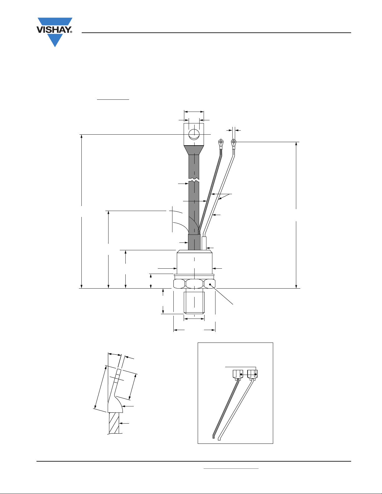
DIMENSIONS in millimeters (inches)
Fast-on terminals
White gate
Red shrink
Red cathode
Red silicon rubber
C.S. 0.51 mm
2
(0.0008 s.i.)
Ø 4.3 (0.17)
19 (0.75) MAX.
Ø 8.5 (0.33)
Glass metal seal
Ø 28.5 (1.12)
MAX.
SW 32
C.S. 35 mm
2
(0.054 s.i.)
Flexible lead
3/4"-16UNF-2A
White shrink
AMP. 280000-1
REF-250
238.5 ± 10
(9.39 ± 0.39)
35 (1.38)
MAX.
21 (0.83)
MAX.
28.5 (1.12)
MAX.
16 (0.63) MAX.
75 (2.95)
MIN.
213.5 ± 10
(8.41 ± 0.39)
23 MIN.
4 MAX.
0° to 15°
38 MAX.
Outline Dimensions
Vishay Semiconductors
TO-209AB (TO-93)
www.vishay.com
Page 8

Legal Disclaimer Notice
www.vishay.com
Vishay
Disclaimer
ALL PRODUCT, PRODUCT SPECIFICATIONS AND DATA ARE SUBJECT TO CHANGE WITHOUT NOTICE TO IMPROVE
RELIABILITY, FUNCTION OR DESIGN OR OTHERWISE.
Vishay Intertechnology, Inc., its affiliates, agents, and employees, and all persons acting on its or their behalf (collectively,
“Vishay”), disclaim any and all liability for any errors, inaccuracies or incompleteness contained in any datasheet or in any other
disclosure relating to any product.
Vishay makes no warranty, representation or guarantee regarding the suitability of the products for any particular purpose or
the continuing production of any product. To the maximum extent permitted by applicable law, Vishay disclaims (i) any and all
liability arising out of the application or use of any product, (ii) any and all liability, including without limitation special,
consequential or incidental damages, and (iii) any and all implied warranties, including warranties of fitness for particular
purpose, non-infringement and merchantability.
Statements regarding the suitability of products for certain types of applications are based on Vishay’s knowledge of typical
requirements that are often placed on Vishay products in generic applications. Such statements are not binding statements
about the suitability of products for a particular application. It is the customer’s responsibility to validate that a particular
product with the properties described in the product specification is suitable for use in a particular application. Parameters
provided in datasheets and/or specifications may vary in different applications and performance may vary over time. All
operating parameters, including typical parameters, must be validated for each customer application by the customer’s
technical experts. Product specifications do not expand or otherwise modify Vishay’s terms and conditions of purchase,
including but not limited to the warranty expressed therein.
Except as expressly indicated in writing, Vishay products are not designed for use in medical, life-saving, or life-sustaining
applications or for any other application in which the failure of the Vishay product could result in personal injury or death.
Customers using or selling Vishay products not expressly indicated for use in such applications do so at their own risk. Please
contact authorized Vishay personnel to obtain written terms and conditions regarding products designed for such applications.
No license, express or implied, by estoppel or otherwise, to any intellectual property rights is granted by this document or by
any conduct of Vishay. Product names and markings noted herein may be trademarks of their respective owners.
Material Category Policy
Vishay Intertechnology, Inc. hereby certifies that all its products that are identified as RoHS-Compliant fulfill the
definitions and restrictions defined under Directive 2011/65/EU of The European Parliament and of the Council
of June 8, 2011 on the restriction of the use of certain hazardous substances in electrical and electronic equipment
(EEE) - recast, unless otherwise specified as non-compliant.
Please note that some Vishay documentation may still make reference to RoHS Directive 2002/95/EC. We confirm that
all the products identified as being compliant to Directive 2002/95/EC conform to Directive 2011/65/EU.
Vishay Intertechnology, Inc. hereby certifies that all its products that are identified as Halogen-Free follow Halogen-Free
requirements as per JEDEC JS709A standards. Please note that some Vishay documentation may still make reference
to the IEC 61249-2-21 definition. We confirm that all the products identified as being compliant to IEC 61249-2-21
conform to JEDEC JS709A standards.
Revision: 02-Oct-12
1
Document Number: 91000
 Loading...