

Page 1
www.vishay.com
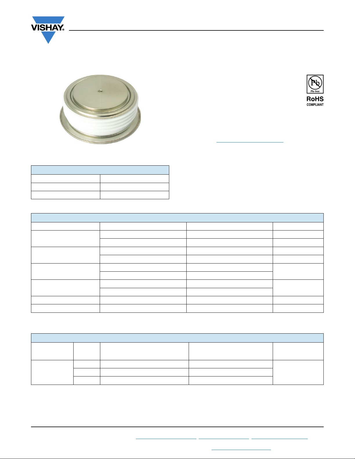
DO-200AC (K-PUK)
Standard Recovery Diodes
(Hockey PUK Version), 3800 A
PRODUCT SUMMARY
I
F(AV)
Package DO-200AC (K-PUK)
Circuit configuration Single diode
3800 A
VS-SD3000C..K Series
Vishay Semiconductors
FEATURES
• Wide current range
• High voltage ratings up to 1000 V
• High surge current capabilities
• Diffused junction
• Hockey PUK version
• Case style DO-200AC (K-PUK)
• Material categorization: For definitions of compliance
please see www.vishay.com/doc?99912
TYPICAL APPLICATIONS
• Converters
• Power supplies
• High power drives
• Auxiliary system supplies for traction applications
MAJOR RATINGS AND CHARACTERISTICS
PARAMETER TEST CONDITIONS VALUES UNITS
I
F(AV)
I
F(RMS)
I
FSM
2
I
t
V
RRM
T
J
T
hs
T
hs
50 Hz 35 800
60 Hz 37 500
50 Hz 6410
60 Hz 5850
Range 400 to 1000 V
3800 A
55 °C
6230 A
25 °C
-40 to 180 °C
ELECTRICAL SPECIFICATIONS
VOLTAGE RATINGS
TYPE NUMBER
VS-SD3000C..K
, MAXIMUM REPETITIVE PEAK
V
VOLTAGE
CODE
04 400 500
10 1000 1100
RRM
REVERSE VOLTAGE
V
V
, MAXIMUM NON-REPETITIVE
RSM
PEAK REVERSE VOLTAGE
V
I
MAXIMUM
RRM
AT T
A
kA2s
= 180 °C
J
mA
7508 800 900
Revision: 15-Apr-14
For technical questions within your region: [email protected]
THIS DOCUMENT IS SUBJECT TO CHANGE WITHOUT NOTICE. THE PRODUCTS DESCRIBED HEREIN AND THIS DOCUMENT
1
ARE SUBJECT TO SPECIFIC DISCLAIMERS, SET FORTH AT www.vishay.com/doc?91000
Document Number: 93543
Page 2
VS-SD3000C..K Series
www.vishay.com
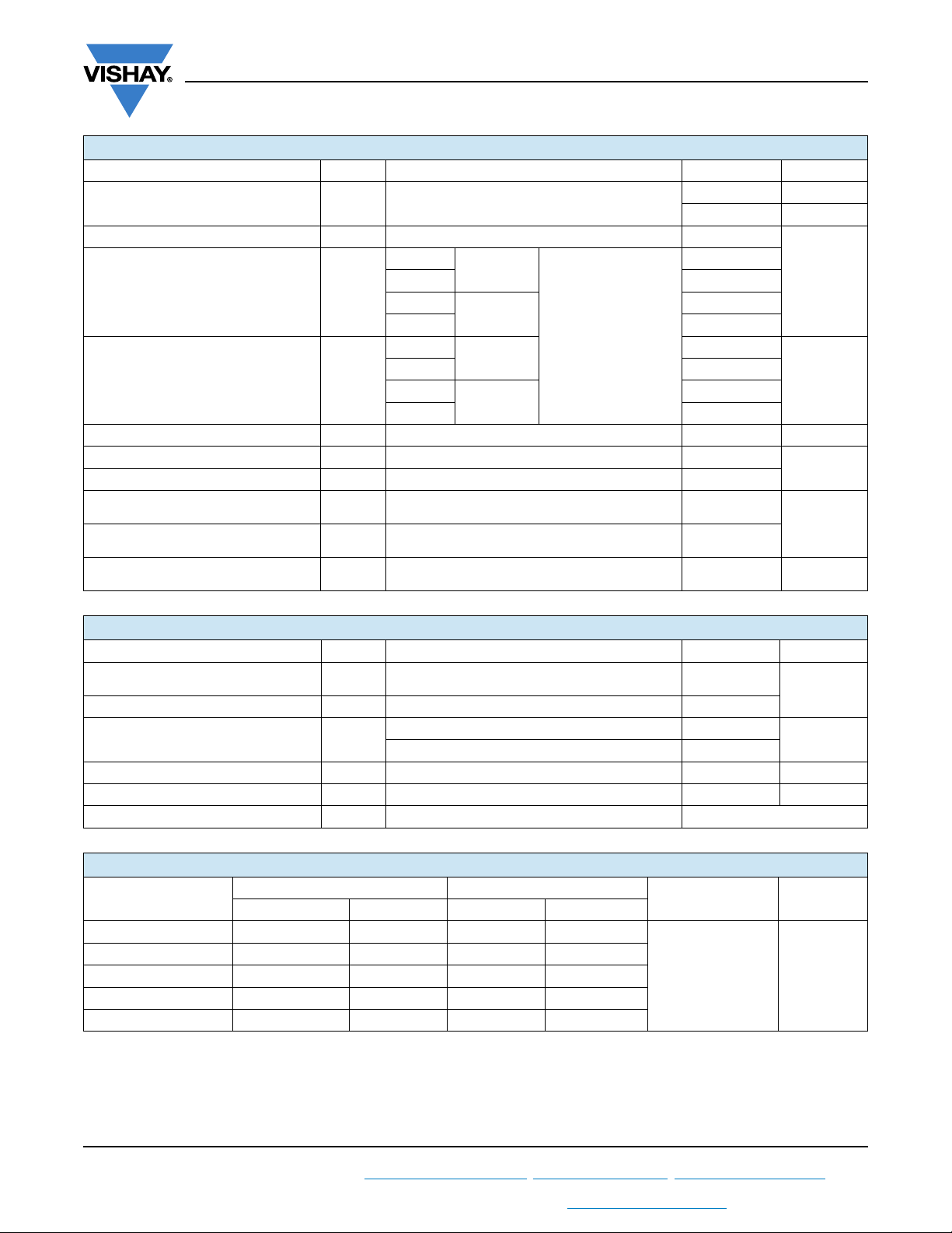
FORWARD CONDUCTION
PARAMETER SYMBOL TEST CONDITIONS VALUES UNITS
Maximum average forward current
at heatsink temperature
Maximum RMS forward current I
Maximum peak, one-cycle forward,
non-repetitive surge current
Maximum I
Maximum I
2
t for fusing I2t
2
√t for fusing I2√t t = 0.1 to 10 ms, no voltage reapplied 64 100 kA2√s
Low level value of threshold voltage V
High level value of threshold voltage V
Low level value of forward
slope resistance
High level value of forward
slope resistance
Maximum forward voltage drop V
I
F(AV)
F(RMS)
I
FSM
F(TO)1
F(TO)2
r
r
180° conduction, half sine wave
Double side (single side) cooled
25 °C heatsink temperature double side cooled 6230
t = 10 ms
t = 8.3 ms 37 500
t = 10 ms
t = 8.3 ms 31 500
t = 10 ms
t = 8.3 ms 5850
t = 10 ms
t = 8.3 ms 4135
(16.7 % x π x I
(I > π x I
(16.7 % x π x I
f1
(I > π x I
f2
Ipk = 6000 A, TJ = TJ maximum
FM
t
= 10 ms sinusoidal wave
p
No voltage
reapplied
100 % V
reapplied
No voltage
RRM
Sinusoidal half wave,
initial T
J
reapplied
100 % V
reapplied
F(AV)
), TJ = TJ maximum 0.86
F(AV)
F(AV)
), TJ = TJ maximum 0.07
F(AV)
RRM
< I < π x I
< I < π x I
), TJ = TJ maximum 0.74
F(AV)
), TJ = TJ maximum 0.08
F(AV)
Vishay Semiconductors
3800 (1925) A
55 (85) °C
35 800
30 100
= TJ maximum
6410
4530
1.22 V
A
kA2s
V
mW
THERMAL AND MECHANICAL SPECIFICATIONS
PARAMETER SYMBOL TEST CONDITIONS VALUES UNITS
Maximum junction operating
temperature range
Maximum storage temperature range T
Maximum thermal resistance,
junction to heatsink
Mounting force, ± 10 % 22 250 (2250) N (kg)
Approximate weight 425 g
Case style See dimensions - link at the end of datasheet DO-200AC (K-PUK)
ΔR
CONDUCTION ANGLE
CONDUCTION
thJ-hs
SINUSOIDAL CONDUCTION RECTANGULAR CONDUCTION
SINGLE SIDE DOUBLE SIDE SINGLE SIDE DOUBLE SIDE
180° 0.002 0.002 0.001 0.001
120° 0.002 0.002 0.002 0.002
90° 0.003 0.003 0.003 0.003
60° 0.004 0.004 0.004 0.004
30° 0.007 0.007 0.007 0.007
Note
• The table above shows the increment of thermal resistance R
R
T
J
Stg
thJ-hs
-40 to 180
-55 to 200
DC operation single side cooled 0.042
DC operation double side cooled 0.020
TEST CONDITIONS UNITS
T
= TJ maximum K/W
J
when devices operate at different conduction angles than DC
thJ-hs
°C
K/W
Revision: 15-Apr-14
For technical questions within your region: [email protected]
THIS DOCUMENT IS SUBJECT TO CHANGE WITHOUT NOTICE. THE PRODUCTS DESCRIBED HEREIN AND THIS DOCUMENT
ARE SUBJECT TO SPECIFIC DISCLAIMERS, SET FORTH AT www.vishay.com/doc?91000
2
Document Number: 93543
Page 3
www.vishay.com
40
60
80
100
120
140
160
180
0 500 1000 1500 2000 2500
30°
60°
90°
120°
180°
A vera g e Fo rw a rd C urre n t ( A)
Maximum Allowable Heatsink Temperature (°C)
Conduction Angle
SD 3 000 C ..K Se rie s
(Single Sid e C ooled )
R (DC ) = 0.042 K/W
thJ-h s
20
40
60
80
100
120
140
160
180
0 1000200030004000
30°
60°
90°
120°
180°
Ave rage F orward Current (A )
Maximum Allowable Heatsink Temperature (°C)
Con duc tion A ngle
SD3000C..K Series
(Double Side Cooled)
R (D C) = 0.020 K/W
th J-hs
0
100 0
200 0
300 0
400 0
500 0
600 0
700 0
0 1000 2000 3000 4000
180°
120°
90°
60°
30°
Averag e Fo rwa rd Curre nt (A)
Maximum Average Forward Power Loss (W )
RMS Limit
Con duc tion Angle
SD3000C..K S erie s
T = 180°C
J
0
100 0
200 0
300 0
400 0
500 0
600 0
700 0
800 0
0 1000 2000 3000 4000 5000 6000 7000
DC
180°
120°
90°
60°
30°
Aver a ge Forwa rd C u rre nt (A)
RMS Limit
Maximum Average Forward Power Loss (W)
Conduction Period
SD 3000C.. K Serie s
T = 180°C
J
VS-SD3000C..K Series
Vishay Semiconductors
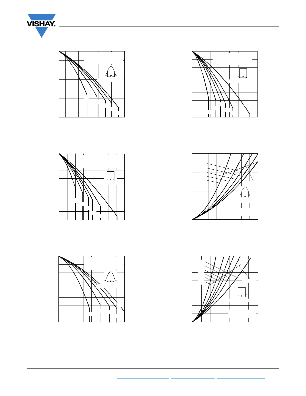
Fig. 1 - Current Ratings Characteristics
180
160
140
120
100
80
60
40
20
01000200030004000
Maxim um Allowable Heatsink Temperature (°C)
SD 30 00C ..K Se rie s
(Single S ide C o oled)
R (DC ) = 0.042 K /W
thJ-h s
C o nd uc ti on Period
30°
60°
90°
120°
180°
Average Forward Current (A)
DC
Fig. 2 - Current Ratings Characteristics
180
160
140
120
100
80
60
40
20
0 1000 2000 3000 4000 5000 6000 7000
Maximum Allowable Heatsink Tem perature ( °C)
SD3000C..K Series
(Double Side Cooled)
R (D C ) = 0 .02 0 K / W
th J-hs
Conduction Period
90°
60°
30°
Average Forw ard Curre nt (A )
120°
180°
DC
Fig. 4 - Current Ratings Characteristics
Fig. 5 - Forward Power Loss Characteristics
Revision: 15-Apr-14
Fig. 3 - Current Ratings Characteristics
For technical questions within your region: [email protected]
THIS DOCUMENT IS SUBJECT TO CHANGE WITHOUT NOTICE. THE PRODUCTS DESCRIBED HEREIN AND THIS DOCUMENT
Fig. 6 - Forward Power Loss Characteristics
3
ARE SUBJECT TO SPECIFIC DISCLAIMERS, SET FORTH AT www.vishay.com/doc?91000
Document Number: 93543
Page 4
www.vishay.com
5000
100 00
150 00
200 00
250 00
300 00
350 00
001011
Number O f Eq ua l Amp litude Ha lf Cycle Cu rrent Pulses (N)
Peak Half Sine Wave Forw ard Current (A)
SD3000C ..K Series
Initial T = 180 °C
@ 60 Hz 0.0083 s
@ 50 Hz 0.0100 s
J
At Any Rated Load Condition And With
Rated V Applied Following Surge.
RRM
100
1000
100 0 0
100000
0.5 1 1.5 2 2.5 3 3.5
T = 25°C
J
Instantaneous Forward Voltage (V)
Instan ta neo us Forwa rd Cur rent (A)
SD3000C..K Series
T = 180°C
J
0.0001
0.001
0.01
0.1
0.00 1 0 .01 0.1 1 1 0 100
Squa re W ave Pulse D ura tion (s)
thJ-h s
Transient Therma l Imp eda nce Z (K/W )
SD 3000C ..K Serie s
Stead y St a te V a lue
R = 0.042 K/W
(Single Sid e C o oled )
R = 0.020 K/W
(Dou ble Sid e Co oled)
(D C O p era tion)
thJ-h s
thJ-h s
VS-SD3000C..K Series
Vishay Semiconductors
40000
M a xim u m N o n Re p e titive S urg e Curre n t
35000
30000
25000
20000
15000
V e rs u s P u ls e T r a in D ura t io n.
Init ial T = 180 °C
No V oltage Reapplied
Rated V Reapplied
J
RRM
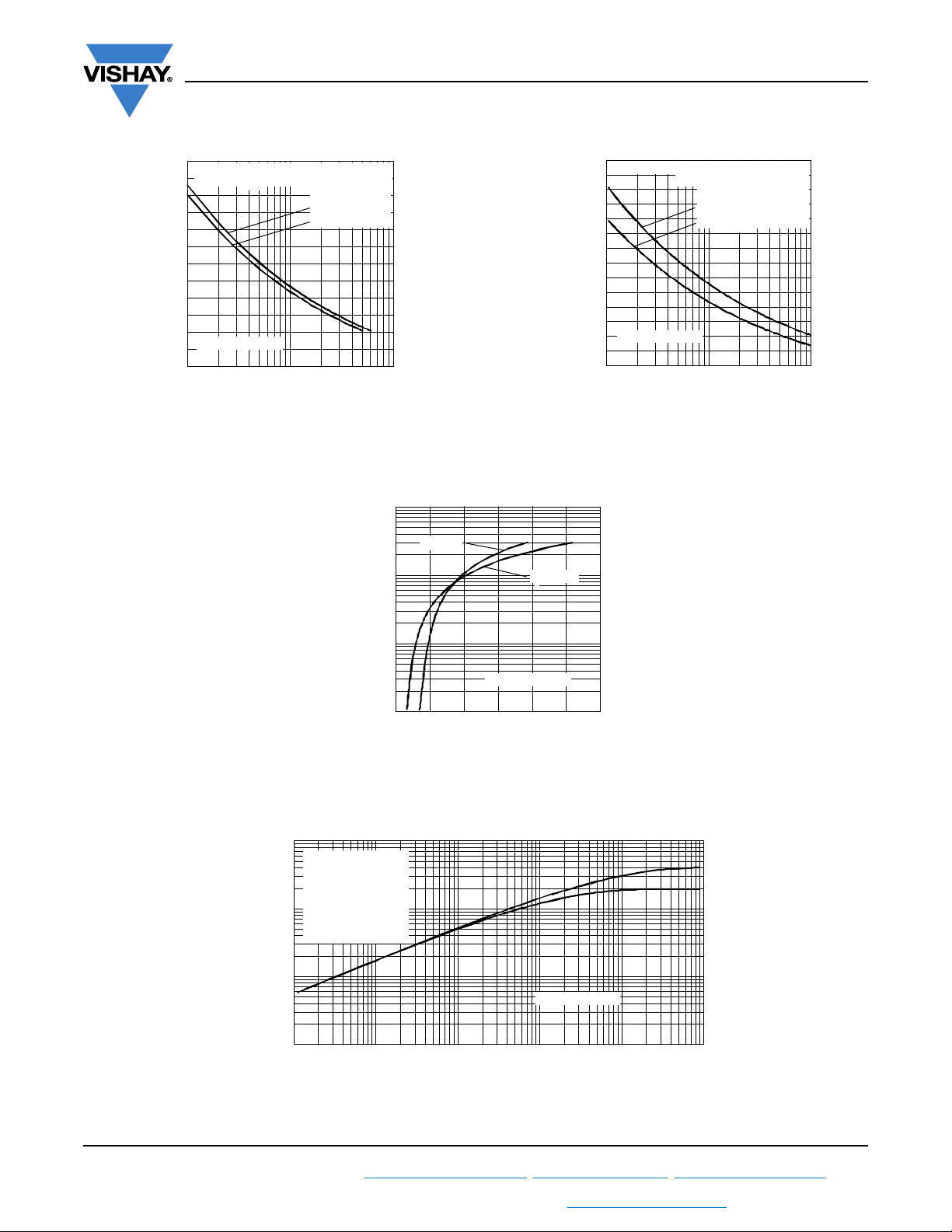
Fig. 7 - Maximum Non-Repetitive Surge Current
Single and Double Side Cooled
Fig. 9 - Forward Voltage Drop Characteristics
10000
Peak Half Sine W ave Forward Current (A)
SD 300 0C ..K Se rie s
5000
0.01 0.1 1
Pulse T ra in D uration (s)
Fig. 8 - Maximum Non-Repetitive Surge Current
Single and Double Side Cooled
Revision: 15-Apr-14
For technical questions within your region: [email protected]
THIS DOCUMENT IS SUBJECT TO CHANGE WITHOUT NOTICE. THE PRODUCTS DESCRIBED HEREIN AND THIS DOCUMENT
ARE SUBJECT TO SPECIFIC DISCLAIMERS, SET FORTH AT www.vishay.com/doc?91000
Fig. 10 - Thermal Impedance Z
Characteristics
thJ-hs
4
Document Number: 93543
Page 5
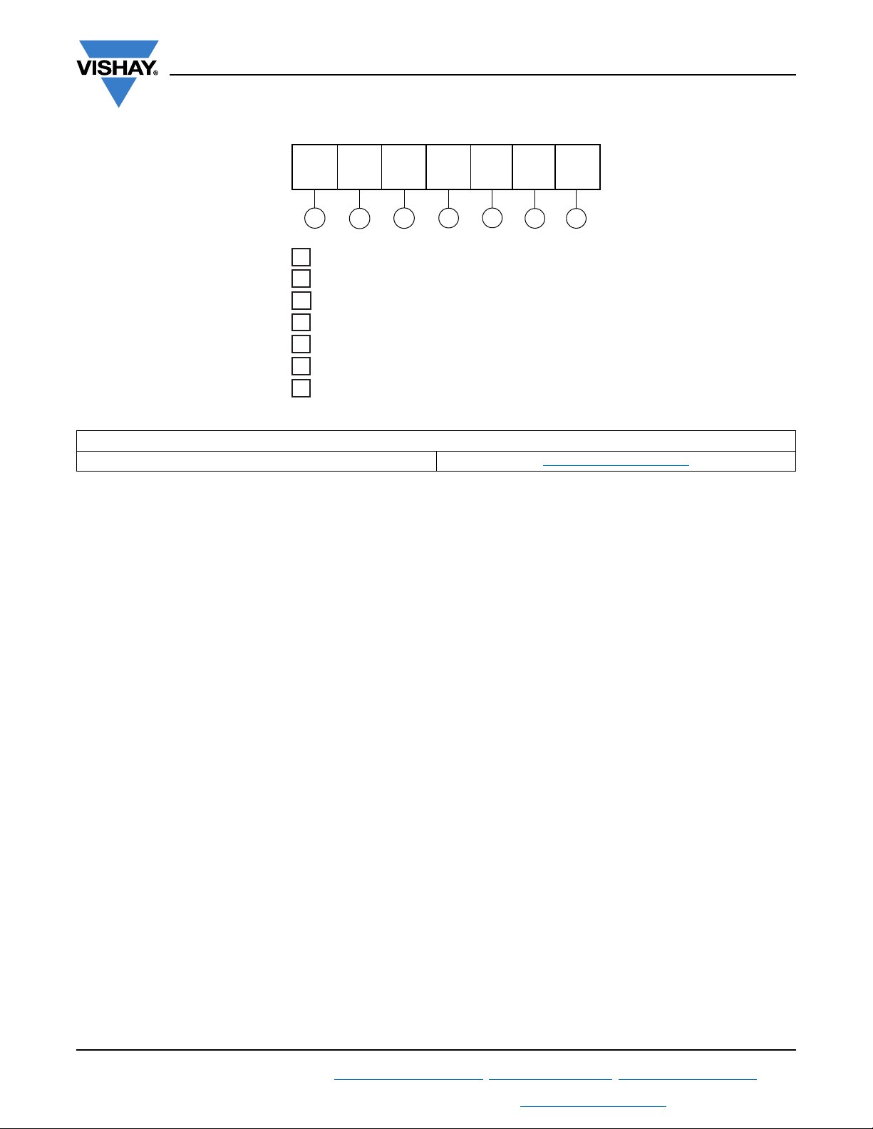
VS-SD3000C..K Series
1
- Diode
2
- Essential part number
3
- 0 = Standard recovery
4
- C = Ceramic PUK
5
- Voltage code x 100 = V
RRM
(see Voltage Ratings table)
6
7
- K = PUK case DO-200AC (K-PUK)
Device code
51 32 4 6 7
SDVS- 300 0 C 10 K
- Vishay Semiconductors product
www.vishay.com
ORDERING INFORMATION TABLE
LINKS TO RELATED DOCUMENTS
Dimensions www.vishay.com/doc?95247
Vishay Semiconductors
Revision: 15-Apr-14
For technical questions within your region: [email protected]
THIS DOCUMENT IS SUBJECT TO CHANGE WITHOUT NOTICE. THE PRODUCTS DESCRIBED HEREIN AND THIS DOCUMENT
ARE SUBJECT TO SPECIFIC DISCLAIMERS, SET FORTH AT www.vishay.com/doc?91000
5
Document Number: 93543
Page 6
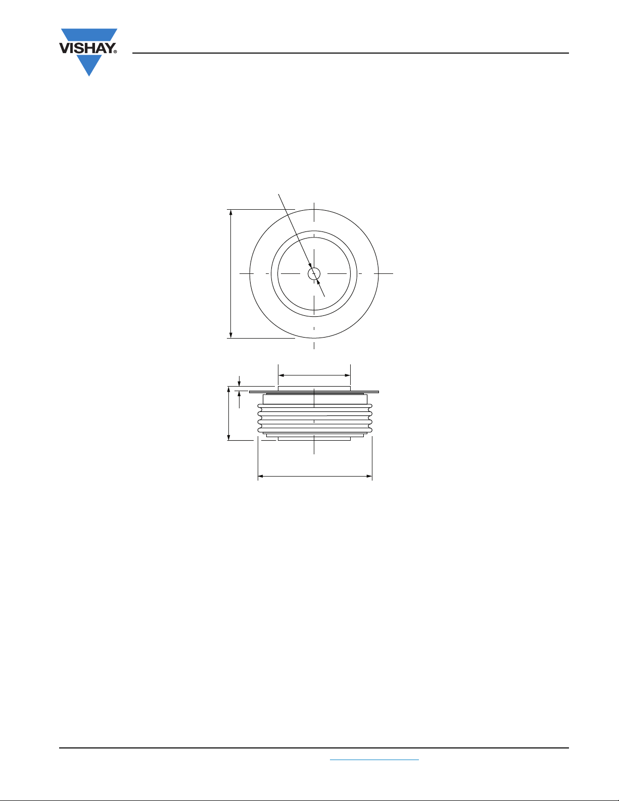
DIMENSIONS in millimeters (inches)
74.5 (2.93) DIA. MAX.
67 (2.64) DIA. MAX.
Quote between upper and lower pole pieces has to be considered after
application of mounting force (see Thermal and Mechanical Specifications)
3.5 (0.14) DIA. NOM. x
1.8 (0.07) deep MIN. both ends
1 (0.04) MIN.
both ends
47.5 (1.87) DIA. MAX.
2 places
27.5 (1.08) MAX.
Outline Dimensions
Vishay Semiconductors
DO-200AC (K-PUK)
www.vishay.com
Page 7

Legal Disclaimer Notice
www.vishay.com
Vishay
Disclaimer
ALL PRODUCT, PRODUCT SPECIFICATIONS AND DATA ARE SUBJECT TO CHANGE WITHOUT NOTICE TO IMPROVE
RELIABILITY, FUNCTION OR DESIGN OR OTHERWISE.
Vishay Intertechnology, Inc., its affiliates, agents, and employees, and all persons acting on its or their behalf (collectively,
“Vishay”), disclaim any and all liability for any errors, inaccuracies or incompleteness contained in any datasheet or in any other
disclosure relating to any product.
Vishay makes no warranty, representation or guarantee regarding the suitability of the products for any particular purpose or
the continuing production of any product. To the maximum extent permitted by applicable law, Vishay disclaims (i) any and all
liability arising out of the application or use of any product, (ii) any and all liability, including without limitation special,
consequential or incidental damages, and (iii) any and all implied warranties, including warranties of fitness for particular
purpose, non-infringement and merchantability.
Statements regarding the suitability of products for certain types of applications are based on Vishay’s knowledge of
typical requirements that are often placed on Vishay products in generic applications. Such statements are not binding
statements about the suitability of products for a particular application. It is the customer’s responsibility to validate that a
particular product with the properties described in the product specification is suitable for use in a particular application.
Parameters provided in datasheets and / or specifications may vary in different applications and performance may vary over
time. All operating parameters, including typical parameters, must be validated for each customer application by the customer’s
technical experts. Product specifications do not expand or otherwise modify Vishay’s terms and conditions of purchase,
including but not limited to the warranty expressed therein.
Except as expressly indicated in writing, Vishay products are not designed for use in medical, life-saving, or life-sustaining
applications or for any other application in which the failure of the Vishay product could result in personal injury or death.
Customers using or selling Vishay products not expressly indicated for use in such applications do so at their own risk.
Please contact authorized Vishay personnel to obtain written terms and conditions regarding products designed for
such applications.
No license, express or implied, by estoppel or otherwise, to any intellectual property rights is granted by this document
or by any conduct of Vishay. Product names and markings noted herein may be trademarks of their respective owners.
Revision: 13-Jun-16
1
Document Number: 91000
 Loading...