

Page 1
www.vishay.com
3
Anode
1
Anode
Base
cathode
2
D2PAK (TO-263AB)
1
2
3
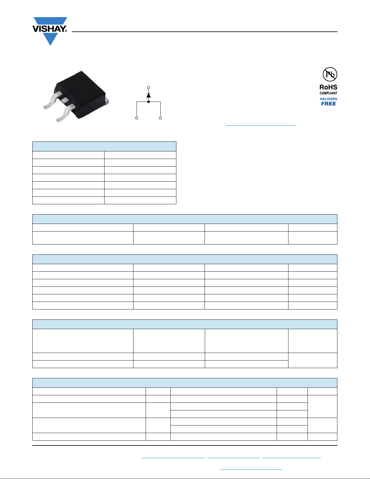
High Voltage Surface Mount Input Rectifier Diode, 20 A
PRIMARY CHARACTERISTICS
I
F(AV)
V
R
V
at I
F
F
I
FSM
T
max. 150 °C
J
Package D
Circuit configuration Single
2
VS-20ETS08S-M3, VS-20ETS12S-M3 Series
Vishay Semiconductors
FEATURES
• Glass passivated pellet chip junction
• Meets MSL level 1, per J-STD-020,
LF maximum peak of 245 °C
• Designed and qualified according to
JEDEC®-JESD 47
• Material categorization: for definitions of compliance
please see www.vishay.com/doc?99912
APPLICATIONS
• Input rectification
20 A
800 V, 1200 V
1.1 V
300 A
PAK (TO-263AB)
• Vishay Semiconductors switches and output rectifiers
which are available in identical package outlines
DESCRIPTION
The VS-20ETS...S-M3 rectifier High Voltage Series has been
optimized for very low forward voltage drop, with moderate
leakage. The glass passivation technology used has reliable
operation up to 150 °C junction temperature.
OUTPUT CURRENT IN TYPICAL APPLICATIONS
APPLICATIONS SINGLE-PHASE BRIDGE THREE-PHASE BRIDGE UNITS
Capacitive input filter T
common heatsink of 1 °C/W
= 55 °C, TJ = 125 °C
A
16.3 21 A
MAJOR RATINGS AND CHARACTERISTICS
SYMBOL CHARACTERISTICS VALUES UNITS
I
F(AV)
V
I
FSM
V
T
RRM
F
J
Sinusoidal waveform 20 A
800/1200 V
300 A
20 A, TJ = 25 °C 1.1 V
-40 to +150 °C
VOLTAGE RATINGS
, MAXIMUM
V
PART NUMBER
RRM
REVERSE VOLTAGE
NON-REPETITIVE PEAK REVERSE
, MAXIMUM PEAK
V
V
VS-20ETS08S-M3 800 900
VS-20ETS12S-M3 1200 1300
RSM
VOLTAGE
I
AT 150 °C
RRM
mA
V
1
ABSOLUTE MAXIMUM RATINGS
PARAMETER SYMBOL TEST CONDITIONS VALUES UNITS
Maximum average forward current I
Maximum peak one cycle
non-repetitive surge current
2
Maximum I
Maximum I
t for fusing I2t
2
t for fusing I2t t = 0.1 ms to 10 ms, no voltage reapplied 4420 A2s
F(AV)
I
FSM
Revision: 27-Oct-17
For technical questions within your region: [email protected]
THIS DOCUMENT IS SUBJECT TO CHANGE WITHOUT NOTICE. THE PRODUCTS DESCRIBED HEREIN AND THIS DOCUMENT
ARE SUBJECT TO SPECIFIC DISCLAIMERS, SET FORTH AT www.vishay.com/doc?91000
TC = 105 °C, 180° conduction half sine wave 20
10 ms sine pulse, rated V
applied 250
RRM
10 ms sine pulse, no voltage reapplied 300
10 ms sine pulse, rated V
applied 316
RRM
10 ms sine pulse, no voltage reapplied 442
1
Document Number: 94889
A
2
s
A
Page 2
VS-20ETS08S-M3, VS-20ETS12S-M3 Series
www.vishay.com
ELECTRICAL SPECIFICATIONS
PARAMETER SYMBOL TEST CONDITIONS VALUES UNITS
Maximum forward voltage drop V
Forward slope resistance r
Threshold voltage V
Maximum reverse leakage current I
F(TO)
RM
20 A, TJ = 25 °C 1.1 V
FM
t
TJ = 150 °C
TJ = 25 °C
= 150 °C 1.0
T
J
= Rated V
V
R
THERMAL - MECHANICAL SPECIFICATIONS
PARAMETER SYMBOL TEST CONDITIONS VALUES UNITS
Maximum junction and storage temperature range T
Maximum thermal resistance,
junction to case
Maximum thermal resistance,
junction to ambient
Typical thermal resistance,
case to heatsink
Approximate weight
Mounting torque
minimum 6.0 (5.0)
maximum 12 (10)
Marking device Case style D
Note
(1)
When mounted on 1” square (650 mm2) PCB of FR-4 or G-10 material 4 oz. (140 μm) copper 40 °C/W
For recommended footprint and soldering techniques refer to application note #AN-994
, T
J
Stg
R
DC operation 1.3
thJC
(1)
R
thJA
R
thCS
For D2PAK version 62
Mounting surface, smooth, and greased 0.5
2
PAK (TO-263AB)
Vishay Semiconductors
10.4 m
0.85 V
RRM
0.1
-40 to +150 °C
2g
0.07 oz.
kgf · cm
(lbf · in)
20ETS08S
20ETS12S
mA
°C/W
150
140
130
120
110
Temperature (°C)
100
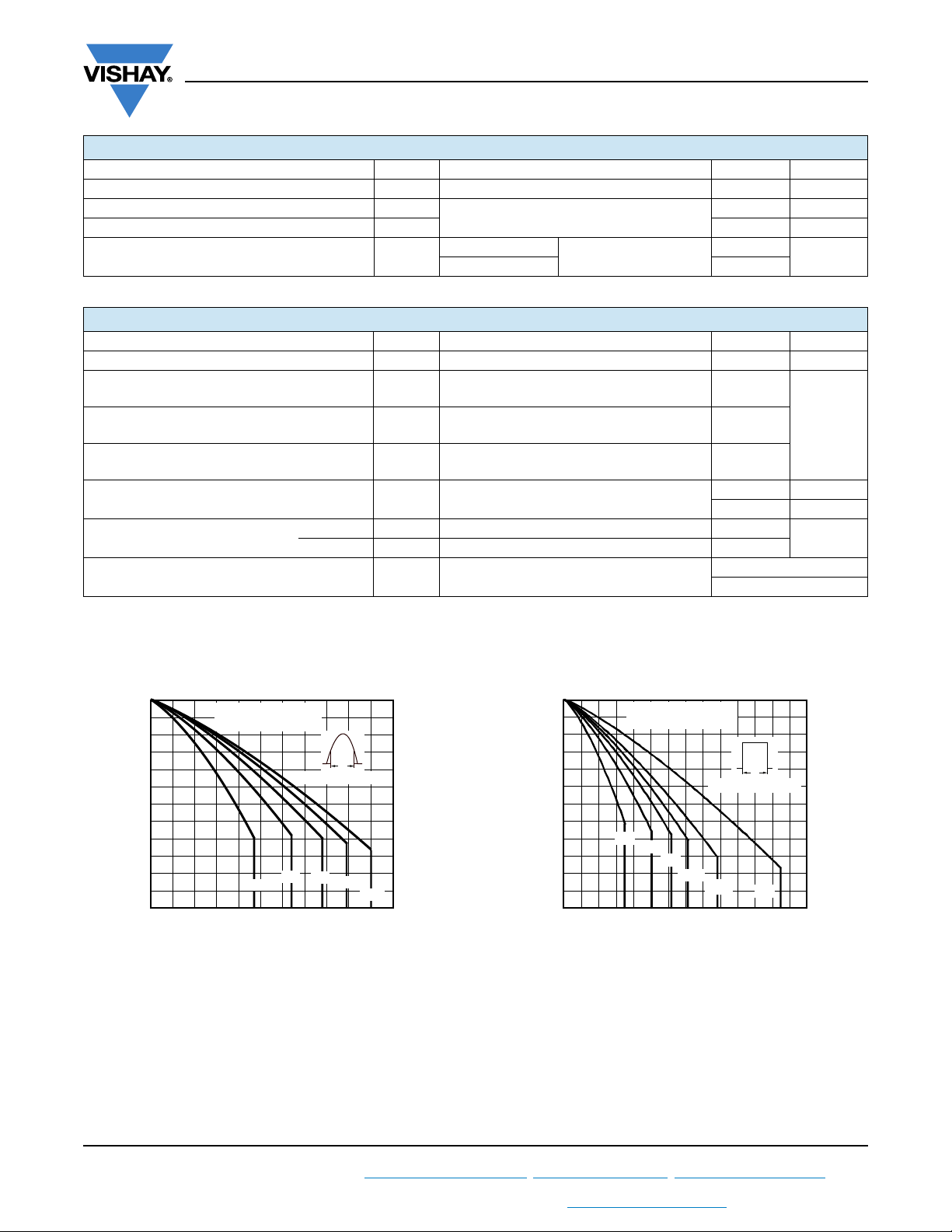
Maximum Allowable Case
10
0
20ETS.. Series
R
thJC
46821012
Average Forward Current (A)
(DC) = 1.3 °C/W
Conduction angle
60°
30°
14 16 18
90°
Ø
120°
180°
20
22
150
140
130
120
110
Temperature (°C)
100
Maximum Allowable Case
90
0
20ETS.. Series
R
thJC
30°
60°
1051520
Average Forward Current (A)
(DC) = 1.3 °C/W
Conduction period
90°
120°
180°
Ø
DC
25
Fig. 1 - Current Rating Characteristics Fig. 2 - Current Rating Characteristics
Revision: 27-Oct-17
For technical questions within your region: [email protected]
THIS DOCUMENT IS SUBJECT TO CHANGE WITHOUT NOTICE. THE PRODUCTS DESCRIBED HEREIN AND THIS DOCUMENT
ARE SUBJECT TO SPECIFIC DISCLAIMERS, SET FORTH AT www.vishay.com/doc?91000
2
Document Number: 94889
30
35
Page 3
www.vishay.com
0
30
35
25
20
15
10
5
Maximum Average Forward
Power Loss (W)
Average Forward Current (A)
20
25
51015
0
DC
180°
120°
90°
60°
30°
RMS limit
20ETS.. Series
T
J
= 150 °C
Ø
Conduction period
1
10
100
1000
Instantaneous Forward Current (A)
Instantaneous Forwad Voltage (V)
1.00.5 1.5 2.0
3.5
4.0
2.5 3.0
0
TJ = 25°C
TJ = 150°C
20ETS.. Series
VS-20ETS08S-M3, VS-20ETS12S-M3 Series
Vishay Semiconductors
30
25
20
15
10
Power Loss (W)
5
Maximum Average Forward
0
0
180°
120°
90°
60°
30°
4
81216
Average Forward Current (A)
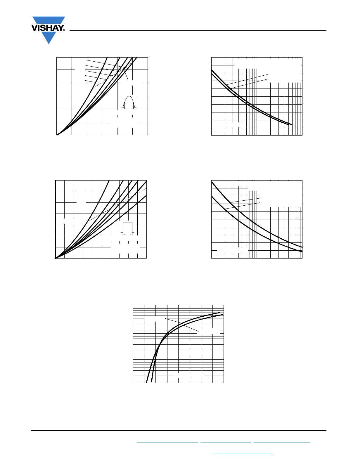
Fig. 3 - Forward Power Loss Characteristics
RMS limit
Ø
Conduction angle
20ETS.. Series
T
= 150 °C
J
20
300
250
200
150
Forward Current (A)
Peak Half Sine Wave
100
20ETS.. Series
24
50
1
At any rated load condition and with
rated V
Number of Equal Amplitude Half
applied following surge.
RRM
10
Initial T
J
at 60 Hz 0.0083 s
at 50 Hz 0.0100 s
= 150 °C
100
Cycle Current Pulse (N)
Fig. 5 - Maximum Non-Repetitive Surge Current
300
250
200
Maximum non-repetitive surge current
versus pulse train duration.
= 150 °C
Initial T
J
No voltage reapplied
Rated V
RRM
reapplied
Fig. 4 - Forward Power Loss Characteristics
Revision: 27-Oct-17
For technical questions within your region: [email protected]
THIS DOCUMENT IS SUBJECT TO CHANGE WITHOUT NOTICE. THE PRODUCTS DESCRIBED HEREIN AND THIS DOCUMENT
150
Forward Current (A)
Peak Half Sine Wave
100
20ETS.. Series
50
0.01
Pulse Train Duration (s)
0.1
Fig. 6 - Maximum Non-Repetitive Surge Current
Fig. 7 - Forward Voltage Drop Characteristics
ARE SUBJECT TO SPECIFIC DISCLAIMERS, SET FORTH AT www.vishay.com/doc?91000
3
1
Document Number: 94889
Page 4
www.vishay.com
0.01
0.1
1
10
0.0001 0.001 0.01 0.1 1
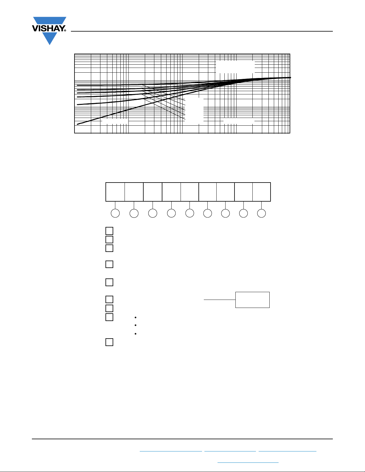
Square Wave Pulse Duration (s)
Z
thJC
- Transient Thermal
Impedance (°C/W)
Steady state value
(DC operation)
Single pulse
D = 0.50
D = 0.33
D = 0.25
D = 0.17
D = 0.08
20ETS.. Series
VS-20ETS08S-M3, VS-20ETS12S-M3 Series
Vishay Semiconductors
ORDERING INFORMATION TABLE
Device code
VS- 20 E T S 12 S TRL -M3
- Vishay Semiconductors product
1
- Current rating (20 = 20 A)
2
3 - Circuit configuration
4
- Package:
T = D
5 - Type of silicon:
S = standard recovery rectifier
6 - Voltage code x 100 = V
S = surface mountable
-
7
8
-
9
- -M3 = halogen-free, RoHS-compliant, and terminations lead (Pb)-free
Fig. 8 - Thermal Impedance Z
Characteristics
thJC
51 32 4 6 7 8 9
E = single
2
PAK (TO-263AB)
RRM
None = tube
TRL = tape and reel (left oriented)
TRR = tape and reel (right oriented)
08 = 800 V
12 = 1200 V
Revision: 27-Oct-17
For technical questions within your region: [email protected]
THIS DOCUMENT IS SUBJECT TO CHANGE WITHOUT NOTICE. THE PRODUCTS DESCRIBED HEREIN AND THIS DOCUMENT
ARE SUBJECT TO SPECIFIC DISCLAIMERS, SET FORTH AT www.vishay.com/doc?91000
4
Document Number: 94889
Page 5
VS-20ETS08S-M3, VS-20ETS12S-M3 Series
www.vishay.com
ORDERING INFORMATION (Example)
PREFERRED P/N QUANTITY PER TUBE MINIMUM ORDER QUANTITY PACKAGING DESCRIPTION
VS-20ETS08S-M3 50 1000 Antistatic plastic tube
VS-20ETS08STRR-M3 800 800 13" diameter reel
VS-20ETS08STRL-M3 800 800 13" diameter reel
VS-20ETS12S-M3 50 1000 Antistatic plastic tube
VS-20ETS12STRR-M3 800 800 13" diameter reel
VS-20ETS12STRL-M3 800 800 13" diameter reel
LINKS TO RELATED DOCUMENTS
Dimensions www.vishay.com/doc?96164
Part marking information www.vishay.com/doc?95444
Packaging information www.vishay.com/doc?96424
SPICE model www.vishay.com/doc?95409
Vishay Semiconductors
Revision: 27-Oct-17
For technical questions within your region: [email protected]
THIS DOCUMENT IS SUBJECT TO CHANGE WITHOUT NOTICE. THE PRODUCTS DESCRIBED HEREIN AND THIS DOCUMENT
ARE SUBJECT TO SPECIFIC DISCLAIMERS, SET FORTH AT www.vishay.com/doc?91000
5
Document Number: 94889
Page 6
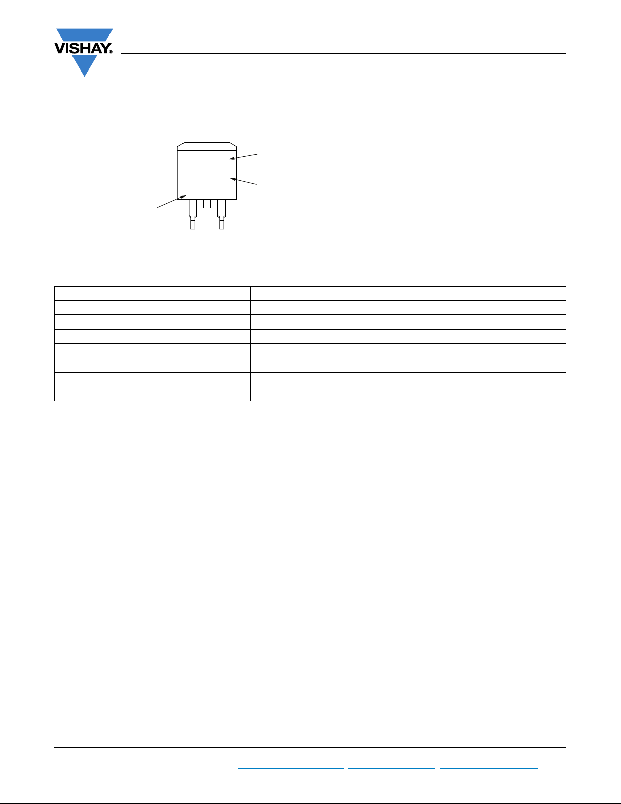
Assembly
lot code
Part number
xxxxxx
(1)
AC
Example: This is a xxxxxx
(1)
with
assembly lot code AC,
assembled on WW 02, 2010
V ZYWWX
Product version (optional):
Z (replaced according below table)
Date code:
Year 0 = 2010
Week 02
Line X
Part Marking Information
www.vishay.com
D2PAK
Note
(1)
If part number contain “H” as last digit, product is AEC-Q101 qualified
ENVIRONMENTAL NAMING CODE (Z) PRODUCT DEFINITION
A Termination lead (Pb)-free
BTotally lead (Pb)-free
E RoHS-compliant and termination lead (Pb)-free
F RoHS-compliant and totally lead (Pb)-free
M Halogen-free, RoHS-compliant, and termination lead (Pb)-free
N Halogen-free, RoHS-compliant, and totally lead (Pb)-free
G Green
Vishay Semiconductors
Revision: 21-Jun-17
For technical questions within your region: [email protected]
THIS DOCUMENT IS SUBJECT TO CHANGE WITHOUT NOTICE. THE PRODUCTS DESCRIBED HEREIN AND THIS DOCUMENT
ARE SUBJECT TO SPECIFIC DISCLAIMERS, SET FORTH AT www.vishay.com/doc?91000
1
Document Number: 95444
Page 7
www.vishay.com
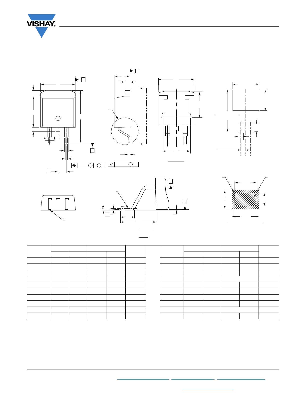
DIMENSIONS in millimeters and inches
®
Conforms to JEDE C
(3)
L1
D
132
L2
BB
2 x
e
outline D2PAK (SMD-220)
(2)(3)
E
4
H
2 x b2
2 x b
0.010
Lead tip
A
(2)
C
M
Detail A
M
A
0° to 8°
B
Gauge
plane
L3
A
c
± 0.004
B
c2
AA
A
M
B
L
L4
Rotated 90 °CW
D2PAK
Detail “A”
Scale: 8:1
(E)
E1
View A - A
H
A1
B
(3)
Seating
plane
Outline Dimensions
Vishay Semiconductors
Pad layout
11.00
MIN.
(0.43)
(D1)
(3)
17.90 (0.70)
15.00 (0.625)
2.32
(0.08)
2.64 (0.103)
2.41 (0.096)
Plating
MIN.
(4)
b1, b3
(c)
(b, b2)
Section B - B and C - C
Scale: None
(0.38)
3.81
(0.15)
9.65
c1
MIN.
MIN.
Base
Metal
(4)
SYMBOL
MILLIMETERS INCHES
MIN. MAX. MIN. MAX. MIN. MAX. MIN. MAX.
NOTES SYMBOL
MILLIMETERS INCHES
NOTES
A 4.06 4.83 0.160 0.190 D1 6.86 8.00 0.270 0.315 3
A1 0.00 0.254 0.000 0.010 E 9.65 10.67 0.380 0.420 2, 3
b 0.51 0.99 0.020 0.039 E1 7.90 8.80 0.311 0.346 3
b1 0.51 0.89 0.020 0.035 4 e 2.54 BSC 0.100 BSC
b2 1.14 1.78 0.045 0.070 H 14.61 15.88 0.575 0.625
b3 1.14 1.73 0.045 0.068 4 L 1.78 2.79 0.070 0.110
c 0.38 0.74 0.015 0.029 L1 - 1.65 - 0.066 3
c1 0.38 0.58 0.015 0.023 4 L2 1.27 1.78 0.050 0.070
c2 1.14 1.65 0.045 0.065 L3 0.25 BSC 0.010 BSC
D 8.51 9.65 0.335 0.380 2 L4 4.78 5.28 0.188 0.208
Notes
(1)
Dimensioning and tolerancing per ASME Y14.5 M-1994
(2)
Dimension D and E do not include mold flash. Mold flash shall not exceed 0.127 mm (0.005") per side. These dimensions are measured at
the outmost extremes of the plastic body
(3)
Thermal pad contour optional within dimension E, L1, D1 and E1
(4)
Dimension b1 and c1 apply to base metal only
(5)
Datum A and B to be determined at datum plane H
(6)
Controlling dimension: inches
(7)
Outline conforms to JEDEC® outline TO-263AB
Revision: 13-Jul-17
For technical questions within your region: [email protected]
THIS DOCUMENT IS SUBJECT TO CHANGE WITHOUT NOTICE. THE PRODUCTS DESCRIBED HEREIN AND THIS DOCUMENT
ARE SUBJECT TO SPECIFIC DISCLAIMERS, SET FORTH AT www.vishay.com/doc?91000
1
Document Number: 96164
Page 8
www.vishay.com
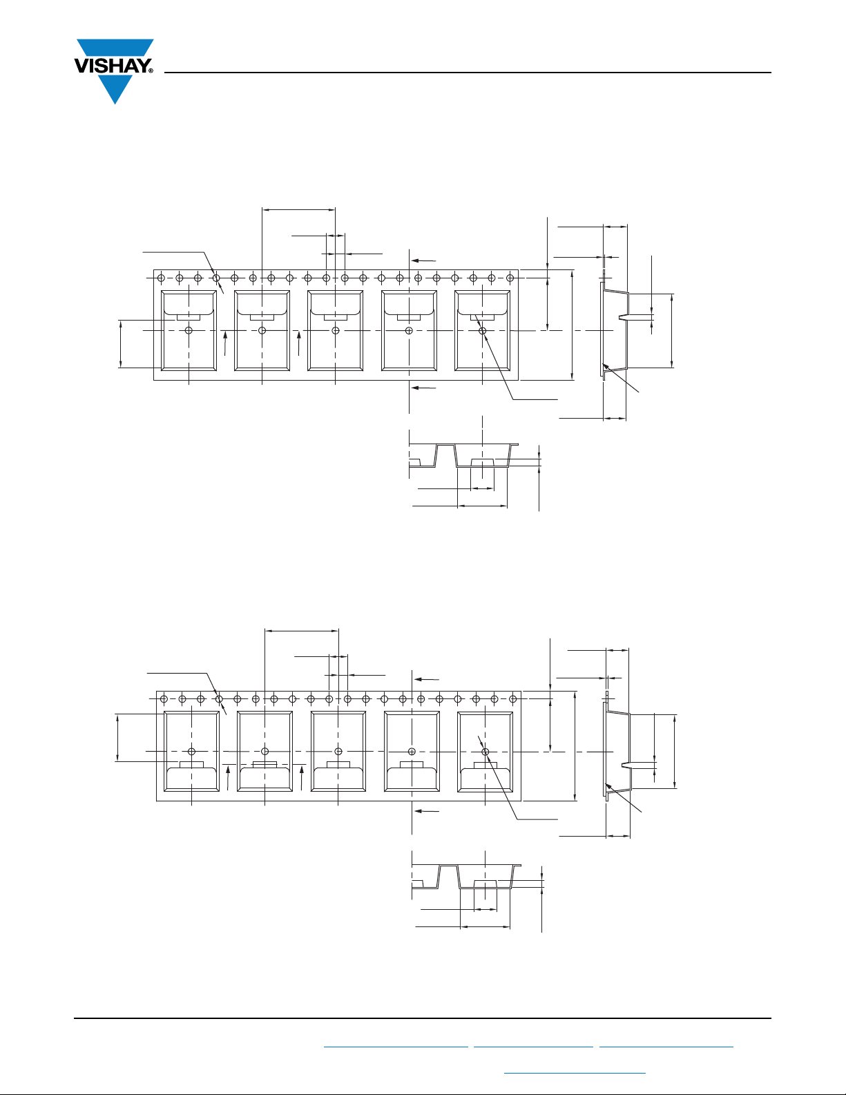
D2PAK (TO-263AB)
CARRIER TAPE FOR TAPE AND REEL LEFT in millimeters
16 ± 0.1
4 ± 0.1
Ø 1.55 ± 0.05
2 ± 0.1
B
Packaging Information
Vishay Semiconductors
5.25 ± 0.2
0.40 ± 0.1
1.75 ± 0.1
1.3 ± 0.1
10.35 ± 0.1
A
A
B
5 ± 0.2
+0.2
Ø 10.8
-0.1
Section A-A
Note
(1)
For dimensions, see next pages
CARRIER TAPE FOR TAPE AND REEL RIGHT in millimeters
16 ± 0.1
4 ± 0.1
Ø 1.55 ± 0.05
2 ± 0.1
B
Ø 1.5
11.5 ± 0.1
+0.25
-0.1
Ø 4.9
1.5 ± 0.2
0.40 ± 0.1
1.75 ± 0.1
24 ± 0.3
Ø 4.9
+0.2
-0.05
+0.2
-0.05
16.13 ± 0.1
Cover tape
Section B-B
(1)
10.35 ± 0.1
11.5 ± 0.1
24 ± 0.3
A
A
B
5 ± 0.2
+0.2
Ø 10.8
-0.1
Section A-A
Ø 1.5
+0.25
-0.1
5.25 ± 0.2
1.5 ± 0.2
1.3 ± 0.1
Cover tape
Note
(1)
For dimensions, see next pages
Revision: 13-Oct-17
For technical questions within your region: [email protected]
THIS DOCUMENT IS SUBJECT TO CHANGE WITHOUT NOTICE. THE PRODUCTS DESCRIBED HEREIN AND THIS DOCUMENT
ARE SUBJECT TO SPECIFIC DISCLAIMERS, SET FORTH AT www.vishay.com/doc?91000
1
Document Number: 96424
Section B-B
16.13 ± 0.1
(1)
Page 9
www.vishay.com
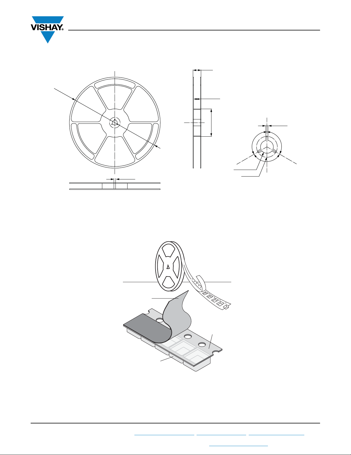
Ø 330 ± 2.0
6.2 ± 0.2
29 ± 1
24.4 ± 0.3
Ø 100 ± 1
2.3 ± 0.2
Ø 13.2 ± 0.2
Ø 21± 0.4
120°
120°
REEL FOR CARRIER TAPE in millimeters
Packaging Information
Vishay Semiconductors
CARRIER TAPE AND REEL PACKAGING D
Top Cover Tape
Component
Cavity
2
PAK (TO-263AB)
Embossed Carrier
Tape
Revision: 13-Oct-17
For technical questions within your region: [email protected]
THIS DOCUMENT IS SUBJECT TO CHANGE WITHOUT NOTICE. THE PRODUCTS DESCRIBED HEREIN AND THIS DOCUMENT
ARE SUBJECT TO SPECIFIC DISCLAIMERS, SET FORTH AT www.vishay.com/doc?91000
2
Document Number: 96424
Page 10
www.vishay.com
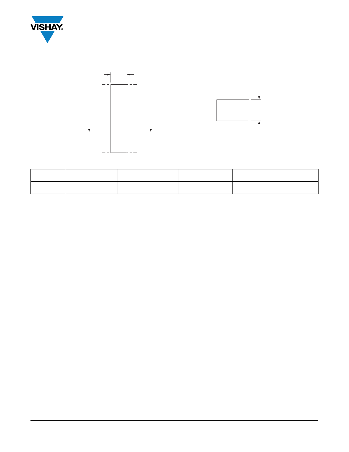
W
YY
Section view:
Section Y - Y
Top view:
T
COVER TAPE FOR CARRIER TAPE in millimeters
Packaging Information
Vishay Semiconductors
APPLICATION
2
D
PAK
(TO-263AB)
COVER TAPE WIDTHWCOVER TAPE THICKNESS
T
21.3 ± 0.1 0.060 ± 0.01 24 Antistatic/treated/transparent/polyester
CARRIER TAPE WIDTH MATERIAL
Revision: 13-Oct-17
For technical questions within your region: [email protected]
THIS DOCUMENT IS SUBJECT TO CHANGE WITHOUT NOTICE. THE PRODUCTS DESCRIBED HEREIN AND THIS DOCUMENT
ARE SUBJECT TO SPECIFIC DISCLAIMERS, SET FORTH AT www.vishay.com/doc?91000
3
Document Number: 96424
Page 11

Legal Disclaimer Notice
www.vishay.com
Vishay
Disclaimer
ALL PRODUCT, PRODUCT SPECIFICATIONS AND DATA ARE SUBJECT TO CHANGE WITHOUT NOTICE TO IMPROVE
RELIABILITY, FUNCTION OR DESIGN OR OTHERWISE.
Vishay Intertechnology, Inc., its affiliates, agents, and employees, and all persons acting on its or their behalf (collectively,
“Vishay”), disclaim any and all liability for any errors, inaccuracies or incompleteness contained in any datasheet or in any other
disclosure relating to any product.
Vishay makes no warranty, representation or guarantee regarding the suitability of the products for any particular purpose or
the continuing production of any product. To the maximum extent permitted by applicable law, Vishay disclaims (i) any and all
liability arising out of the application or use of any product, (ii) any and all liability, including without limitation special,
consequential or incidental damages, and (iii) any and all implied warranties, including warranties of fitness for particular
purpose, non-infringement and merchantability.
Statements regarding the suitability of products for certain types of applications are based on Vishay’s knowledge of
typical requirements that are often placed on Vishay products in generic applications. Such statements are not binding
statements about the suitability of products for a particular application. It is the customer’s responsibility to validate that a
particular product with the properties described in the product specification is suitable for use in a particular application.
Parameters provided in datasheets and / or specifications may vary in different applications and performance may vary over
time. All operating parameters, including typical parameters, must be validated for each customer application by the customer’s
technical experts. Product specifications do not expand or otherwise modify Vishay’s terms and conditions of purchase,
including but not limited to the warranty expressed therein.
Except as expressly indicated in writing, Vishay products are not designed for use in medical, life-saving, or life-sustaining
applications or for any other application in which the failure of the Vishay product could result in personal injury or death.
Customers using or selling Vishay products not expressly indicated for use in such applications do so at their own risk.
Please contact authorized Vishay personnel to obtain written terms and conditions regarding products designed for
such applications.
No license, express or implied, by estoppel or otherwise, to any intellectual property rights is granted by this document
or by any conduct of Vishay. Product names and markings noted herein may be trademarks of their respective owners.
© 2017 VISHAY INTERTECHNOLOGY, INC. ALL RIGHTS RESERVED
Revision: 08-Feb-17
1
Document Number: 91000
 Loading...