

Page 1
Vicor Corp. Tel: 800-735-6200, 978-470-2900 Fax: 978-475-6715 ARM, Autoranging Rectifier Module Rev. 2.4 Page 1 of 12
Set your site on VICOR at www.vicorpower.com
VI-ARM
TM
Autoranging Rectifier Modules
Up to 1500 Watts
45
Features
• Autoranging input
• Microprocessor controlled
• VI-ARM-1
500 Watts @ 90-132Vac
750 Watts @ 180-264Vac
• VI-ARM-2
1000 Watts @ 90-132Vac
1500 Watts @ 180-264Vac
• 96-98% Efficiency
• 100˚C baseplate (no derating)
• UL, CSA, TÜV, VDE, BABT
• AC Bus OK, module enable
• Inrush limiting (no external circuitry)
• CE Marked
Typical Applications: systems requiring a
rugged, full featured interface to the AC
mains in the smallest possible package.
Product Highlights
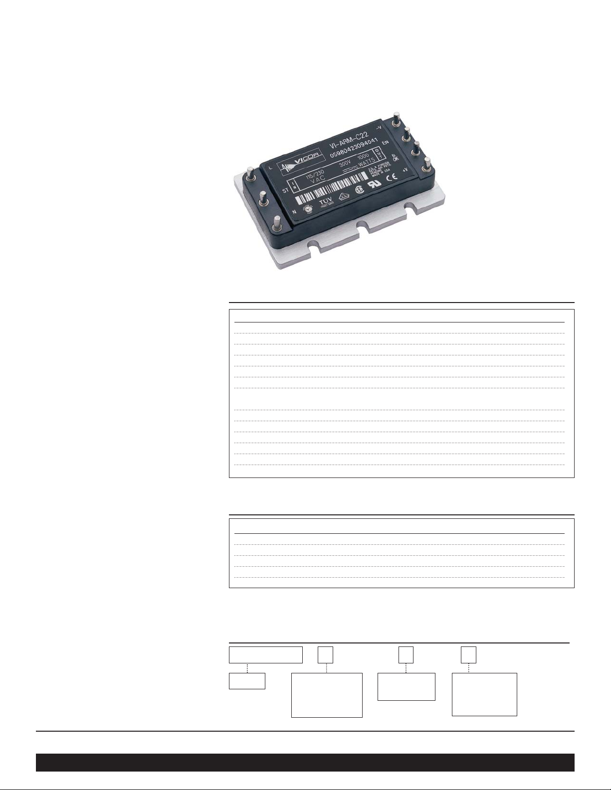
The ARM (Autoranging Rectifier Module)
is an AC front end module which provides
autoranging line rectification and inrush
current limiting. The ARM is available in
either 500/750W or 750/1000W models in a
mini sized package measuring only 2.28" x
1.45" x 0.5".
The ARM interfaces directly with
worldwide AC mains and may be used with
Vicor 1st or 2nd Generation 300V input
DC-DC converters to realize an
autoranging, high density, low profile
switching power supply. The ARM includes
a microcontroller that continuously
monitors the AC line to control
bridge/doubler operation. The user need
only provide external capacitance to satisfy
system hold-up requirements.
Vicor 2nd Generation packaging technology
offers flexible mounting options for various
manufacturing processes. The ARM may be
installed as a conventional leaded device
for on-board applications, in-board for low
profile, height restricted applications,
socketed or surface mounted with optional
ModuMate interconnect products.
Actual size:
2.28 x 1.45 x 0.5 in
57,9 x 36,8 x 12,7 mm
Parameter Rating
VI-ARM-1/VI-ARM-2 Unit Notes
L to N 264 Vac
L to N 280 Vac 100ms
+Out to –Out 400 Vdc
B OK to –Out 16 Vdc
EN to –Out 16 Vdc
Output power 500/1000 Watts 90-132Vac
750/1500 Watts 180-264Vac
Mounting torque 4 - 6 (0.45 -0.68) in- lbs (N-m) 6 each, 4-40 screw
Pin soldering temperature 500 (260) °F (°C) <5 sec; wave solder
Pin soldering temperature 750 (390) °F (°C) <7 sec; hand solder
Storage temperature, C–,& T– Grade –40 to +125 °C Baseplate
Operating temperature, C–Grade –20 to +100 °C Baseplate
Operating temperature, T– Grade –40 to +100 °C Baseplate
Parameter Typ Unit
Baseplate to sink; flat, greased surface 0.24 °C/Watt
Baseplate to sink; with thermal pad (P/N 16495) 0.3 °C/Watt
Baseplate to ambient- free convection 15 °C/Watt
Baseplate to ambient; 1000 LFM- forced air 2.7 °C/Watt
Thermal capacity 48 Watt-sec/°C
Product
Type
1 = 500/1000W
2 = 750/1500W
Pin Style*
1 = Short
2 = Long
S=Short Modumate
N=Long Modumate
Product Grade
C = –20°C to +100°C
T = –40°C to +100°C
H = –40°C to +100°C
M = –55°C to +100°C
Thermal Resistance and Capacity
Absolute Maximum Ratings
Part Numbering
*Pin styles S & N are compatible with the ModuMate interconnect system for socketing and surface mounting.
VI-ARM- C 1 2
Page 2

Vicor Corp. Tel: 800-735-6200, 978-470-2900 Fax: 978-475-6715 ARM, Autoranging Rectifier Module Rev. 2.4 Page 2 of 12
Set your site on VICOR at www.vicorpower.com
VI-ARM - 1 VI-ARM - 2
Parameter Min Typ Max Min Typ Max Unit Notes
Operating input voltage 90 132 90 132 Vac Autoranging (doubler mode)
Operating input voltage 180 264 180 264 Vac Autoranging (bridge mode)
Input undervoltage 90 90 Vac No damage
Input surge withstand 280 280 Vac 100ms
AC line frequency 47 63 47 63 Hz C-Grade
AC line frequency 47 880 47 880 Hz T-Grade
Input current, rms 0 7.4 0 14.8 Amps 120Vac
Input current, rms 0 5.4 0 10.8 Amps 240Vac
Power factor 0.60 0.60 Typical line voltage condition
Inrush current 30 60 Amps 264Vac peak line, cold start
Holdup capacitance 1600 3300 µF
SAFETY SPECIFICATIONS
MODULE INPUT SPECIFICATIONS
MODULE OUTPUT SPECIFICATIONS
Electrical Characteristics
Electrical characteristics apply over the full operating range of input voltage, output load (resistive) and baseplate temperature,
unless otherwise specified. All temperatures refer to the operating temperature at the center of the baseplate. Specifications apply
for AC mains having up to 5% total harmonic distortion.
VI-ARM - 1 VI-ARM - 2
Parameter Min Typ Max Min Typ Max Unit Notes
Output power 0 500 0 1000 Watts 90-132Vac
Output power 0 750 0 1500 Watts 180-264Vac
Efficiency, 120Vac 94 96 94 96 %
Efficiency, 240Vac 96 98 96 98 %
Output voltage 200 375 200 375 Vdc 90-264Vac
Parameter Min Typ Max Unit Notes
Agency approvals
UL 1950, CSA 22.2 No.950,
TÜV, VDE, EN60950, CE Marked
Isolation voltage (in to out) None Isolation provided by DC-DC converter(s)
Isolation voltage (I/O to baseplate) 1500 Volts, rms
Leakage current 100 µA No filter
Page 3

Vicor Corp. Tel: 800-735-6200, 978-470-2900 Fax: 978-475-6715 ARM, Autoranging Rectifier Module Rev. 2.4 Page 3 of 12
Set your site on VICOR at www.vicorpower.com
Electrical Characteristics, continued
MODULE CONTROL SPECIFICATIONS
MODULE GENERAL SPECIFICATIONS
Parameter Min Typ Max Unit Notes
AC Bus OK (B OK)
On-state resistance (low) 15 Ω To negative output - bus normal
On-state current (low) -50 mA Bus normal
Off-state voltage 14.8 15.0 15.2 Vdc Bus abnormal, 27K internal pull up to 15Vdc (Fig. 10)
On-state threshold 235 240 245 Vdc Output bus voltage
Off-state threshold 200 205 210 Vdc Output bus voltage
Module Enable (EN)
On-state resistance (low) 15 Ω To negative output - converters are disabled
On-state current (low) 50 mA
Off-state voltage 14.8 15.0 15.2 Vdc 150K internal pull up to 15Vdc (Fig. 9)
On-state threshold 235 240 245 Vdc Output bus voltage
Off-state threshold 200 205 210 Vdc Output bus voltage
Over voltage shutdown 380 390 400 Vdc
AC Bus OK - module enable, differential error* 15 17 20 Vdc AC Bus OK and module enable thresholds track
Parameter Min Typ Max Unit Notes
MTBF >1,000,000 hours 25˚C, ground benign
Baseplate material Aluminum
Cover Polyetherimide
Pin material Copper, tin/lead solder dipped
Weight 2.1 (60) ounces (grams)
Size
2.28 x 1.45 x 0.5 inches
(57,9 x 36,8 x 12,7) (mm)
* Tracking error between BUS OK and Enable thresholds
Page 4
Vicor Corp. Tel: 800-735-6200, 978-470-2900 Fax: 978-475-6715 ARM, Autoranging Rectifier Module Rev. 2.4 Page 4 of 12
Set your site on VICOR at www.vicorpower.com
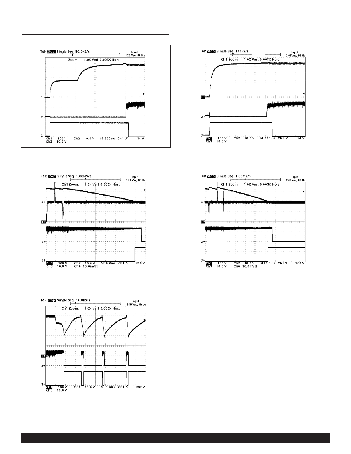
Operating Characteristics
Figure 1—Start-up at 120Vac input
Figure 3—Power down, from 120Vac Figure 4—Power down, from 240Vac
Figure 2—Start-up at 240Vac input
Vdc output
Strap
Engaged
Iac input @2A / mV
Iac input @2A / mV
Enable
Enable
B OK
Vdc output
Enable
B OK
Vdc output
Enable
B OK
Vdc output
Enable
B OK
Figure 5—Output overvoltage protection 240Vac range
Vdc output
Enable
B OK
➞
Page 5

Vicor Corp. Tel: 800-735-6200, 978-470-2900 Fax: 978-475-6715 ARM, Autoranging Rectifier Module Rev. 2.4 Page 5 of 12
Set your site on VICOR at www.vicorpower.com
The VI-ARM Autoranging Rectifier Module (ARM) provides
an effective solution for the AC front end of a power supply
built with Vicor DC-DC converters. This high performance
power system building block satisfies a broad spectrum of
requirements and agency standards.
The ARM contains all of the power switching and control
circuitry necessary for autoranging rectification, inrush current
limiting, and overvoltage protection. This module also provides
converter enable and status functions for orderly power
up/down control or sequencing. To complete the AC front end
configuration, the user needs only to add holdup capacitors and
a suitable input filter with transient protection.
Functional Description
The switch that bypasses the inrush limiting PTC (positive
temperature coefficient) thermistor is open when power is
applied, as is the switch that engages the strap for voltage
doubling. (
See Fig. 6). In addition, the converter modules are
disabled via the Enable (EN) line, and Bus-OK (B OK) is high.
Power-Up Sequence. (See Fig. 7).:
Upon application of input power, the output bus capacitors
begin to charge. The thermistor limits the charge current,
and the exponential time constant is determined by the
holdup capacitor value and the thermistor cold resistance.
The slope (dv/dt) of the capacitor voltage approaches
zero as the capacitors become charged to the peak of the
AC line voltage.
If the bus voltage is less than 200V as the slope nears
zero, the voltage doubler is activated, and the bus voltage
climbs exponentially to twice the peak line voltage.
If the bus voltage is greater than 200V, the doubler is
not activated.
If the bus voltage is greater than 235V as the slope
approaches zero, the inrush limiting thermistor is
bypassed. Below 235V, the thermistor is not bypassed.
The converters are enabled 50 milliseconds after the
thermistor bypass switch is closed.
Bus-OK is asserted after an additional 50 millisecond
delay to allow the converter outputs to settle within
specification.
Power-Down Sequence. (See Fig. 7). When input power is
turned off or fails, the following sequence occurs as the bus
voltage decays:
Bus-OK is deasserted when the bus voltage falls below
205Vdc (Typ.).
The converters are disabled when the bus voltage falls
below 200Vdc. If power is reapplied after the converters
are disabled, the entire power-up sequence is repeated. If
a momentary power interruption occurs and power is
reestablished before the bus reaches the disable threshold,
the power-up sequence is not repeated.
Application Note
Figure 6—Functional block diagram
Figure 7—Timing diagram: power up/down sequence
1.1
2.1
3.1
4.1
5.1
1.2
2.2
Power
400
300
200
100
Up
1. 1
0
2.1
3.1
50ms
4.1
5.1
50ms
+Out
PTC
L
Thermistor
N
Microcontroller
Strap
Strap
–Out
EN
BOK
90–132V
AC Line
Output
Bus
(Vdc)
Strap
PTC
Thermistor
Bypass
Converter
Enable
Bus OK
Power
Down
2.2
1.2
Page 6

Vicor Corp. Tel: 800-735-6200, 978-470-2900 Fax: 978-475-6715 ARM, Autoranging Rectifier Module Rev. 2.4 Page 6 of 12
Set your site on VICOR at www.vicorpower.com
Figure 8—Converter connections
Application Note, continued
Off-Line Power Supply Configuration
The ARM maintains the DC output bus voltage between 200
and 375Vdc over the entire universal input range, which is
compatible with Vicor VI-260 series and VI-J60 series DC-DC
converters, as well as next-generation 300V input Vicor
converters. The ARM automatically switches to the proper
rectification mode (doubled or undoubled) depending on the
input voltage, eliminating the possibility of damage due to
improper line connection. The ARM–1 is rated at 500W in the
low range (90-132Vac input), and 750W in the high range
(180-264Vac input). The ARM–2 is rated for 1000W and
1500W for the low and high input ranges respectively. Either
of these modules can serve as the AC front end for any number
and combination of compatible converters as long as the
maximum power rating is not exceeded.
Strap (ST) Pin. In addition to input and output power pin
connections, it is necessary to connect the Strap pin to the
junction of the series holdup capacitors (
C1, C2, Fig. 8)
for proper (autoranging) operation. Gas tubes across the
capacitors provide input transient protection. The bleeder
resistors (
R1, R2, Fig. 8) discharge the holdup capacitors when
power is switched off.
Enable (EN) Pin. (See Fig. 9). The Enable pin must be
connected to the Gate-In or PC pin of all converter modules to
disable the converters during power-up. Otherwise, the
converters would attempt to start while the holdup capacitors
were being charged through an unbypassed thermistor,
preventing the bus voltage from reaching the thermistor
bypass threshold thus disabling the power supply. The Enable
output (the drain of an N channel MOSFET) is internally
pulled up to 15V through a 150kΩ resistor.
A signal diode should be placed close to and in series with the
Gate-In pin of each converter to eliminate the possibility of
control interference between converters. The Enable pin
switches to the high state (15V) with respect to the negative
output power pin to turn on the converters after the power-up
inrush is over. The Enable function also provides input
overvoltage protection for the converters by turning off the
converters if the DC bus voltage exceeds 400Vdc. The
thermistor bypass switch opens if this condition occurs,
placing the thermistor in series with the input voltage, which
reduces the bus voltage to a safe level while limiting input
current in case the gas tubes fire. The thermistor bypass switch
also opens if a fault or overload reduces the bus voltage to less
than 180Vdc.
Holdup Box (HUB)
820µF HUB820-S, 2200µF HUB2200-S
1200µF HUB1200-S, 2700µF HUB2700-S
1800µF HUB1800-S, 3300µF HUB3300-S
N
Filter
Z1
Part
C1,2
C3–6
R1,2
V1,2
F1,2
D1,2
*
C7,8
Z1
D3,D4
C10,C11
R3
Sizing PCB traces:
All traces shown in bold carry significant
current and should be sized accordingly.
VI-ARM- _12
N/ST/L
+/– In
*
VI-ARM- _22
N/ST/L
+/– In
Required if C1 & C2 are located more than
6 inches from output of VI-ARM.
ST
L
Description
Holdup capacitors
4700pF
150kΩ, 0.5W
220V MOV
3A, PC Tron
Diode
Film Cap., 0.8µf
MOV
1N5817
0.001µF
500Ω
10A rms at 90Vac and 500W
4A DC at 190Vdc and 750W
20A rms at 90Vac and 1000W
8A DC at 190Vdc and 1500W
VI-ARM
Vicor
Part Number
see text
01000
00127-1503
13755
02178
00670
03040
26108
+V
BOK
EN
–V
R1R2C1
V1
C7*
C8*
V2
R3
D1
D2
To additional modules
C2
D4
C3
F1
D3
F2
C10
C11
C4
C5
C6
+In
Gate In (PC)
Gate Out (PR)
–In
+In
Gate In (PC)
Gate Out (PR)
–In
Vicor DC-DC
Converter
Vicor DC-DC
Converter
Page 7

Vicor Corp. Tel: 800-735-6200, 978-470-2900 Fax: 978-475-6715 ARM, Autoranging Rectifier Module Rev. 2.4 Page 7 of 12
Set your site on VICOR at www.vicorpower.com
Application Note, continued
o
D
r
Figure 9—Enable (EN) function; See Fig.8 for details
D
o
Figure 10—Bus OK (B OK) isolated power status indicator
Figure 11—Filter connections
Bus-OK (B OK) Pin. (See Fig. 10). The Bus-OK pin is
intended to provide early-warning power fail information
and is also referenced to the negative output pin.
Caution: There is no input to output isolation in the ARM.
It is necessary to monitor Bus-OK via an optoisolator if it is to
be used on the secondary (output) side of the converters. Aline
isolation transformer should be used when performing scope
measurements. Scope probes should never be applied
simultaneously to the input and output as this will destroy the unit.
Filter. Two input filter recommendations are shown for low
power VI-ARM-1 and high power VI-ARM-2 (
See Fig. 11).
Both filter configurations provide sufficient common mode and
differential mode insertion loss in the frequency range between
100kHz and 30MHz to comply with the Level B conducted
emissions limit.
Hold-up Capacitors. Hold-up capacitor values should be
determined according to output bus voltage ripple, power fail
hold-up time, and ride-through time. (See Fig. 12). Many
applications require the power supply to maintain output
regulation during a momentary power failure of specified
duration, i.e., the converters must hold-up or ride-through such
an event while maintaining undisturbed output voltage
regulation. Similarly, many of these same systems require
notification of an impending power failure in order to allow time
to perform an orderly shutdown.
The energy stored on a capacitor which has been charged to
voltage V is:
ε = 1/2(CV
2
) (1)
Where: ε = stored energy
C = capacitance
V= voltage across the capacitor
Energy is given up by the capacitors as they are discharged by
the converters. The energy expended (the power-time product)
is:
ε = P∆t = C(V
1
2
–V
2
2
) / 2 (2)
Where: P = operating power
∆t = discharge interval
V
1
= capacitor voltage at the beginning of ∆t
V
2
= capacitor voltage at the end of ∆t
Rearranging equation 2 to solve for the required capacitance:
C = 2P∆t / (V
1
2
–V
2
2
) (3)
High power filter connections
Low power filter connections
Vicor
DC-DC
Converter
Vicor
DC-DC
Converter
+In
N
ST
L
150kΩ
Micro-
controller
15Vdc
+V
BOK
EN
–V
To additional modules
Gate In (PC)
Gate Out (PR)
–In
+In
Gate In (PC)
Gate Out (PR)
–In
N
ST
L
Micro-
controller
27kΩ
15Vdc
+V
BOK
EN
–V
+5 Vdc
Secondary
referenced
To additional modules
Vic
DC-
Conve
C
R1
L2/N
L1
GND
Z1
F1
L2
R2
L1
C1
L3
R3
Vicor
Description
1.0µF
4700pF
0.15µF
12A fuse
27µH
1.3mH
10Ω
150kΩ, 0.5W
2.2Ω
MOV
Part Number
02573
01000
03269
05147
14563
15016
00127-1503
03040
C2
R4
C3
C4
Part
C1
N
C2, C3
ST
C4
F1
L
L1, L2
L3
R1, R2
R3
R4
Z1
R2
10
L2/N
GND
C1
390K
Z1
L1
F1
R1
1/2W
1/2W
L3
L1
L2
4700pF
4700pF
N
C6
.22µF
ST
(X2)
L
Vicor
Part Number
02134
11479
02573
03285
04068
L4
C4
4700pF
C5
4700pF
Description
1000µH 12A/6.5MΩ
22µH
.68µf (x type)
4700pf
.22µf (x type)
1
/
W
390k
2
10Ω 1/
W
2
17A/250V
MOV 03040
C3
C2
Part
L1,L4
L2, L3
C1
C2,C3,C4,C5
C6
R1
R2
F1
Z1
Page 8

Vicor Corp. Tel: 800-735-6200, 978-470-2900 Fax: 978-475-6715 ARM, Autoranging Rectifier Module Rev. 2.4 Page 8 of 12
Set your site on VICOR at www.vicorpower.com
Application Note, continued
Figure 13—Hold-up time vs. operating power and total bus
capacitance, series combination of C1, C2 (Fig. 8)
Figure 15—Ripple voltage vs. operating power and bus
capacitance, series combination of C1, C2 (see Fig. 8)
Figure 14—Ride-through time vs. operating power
Figure 12—Hold-up time
The holdup time (∆t) is defined as the interval between power
fail warning (B OK) and converter shutdown (EN) as illustrated
in Fig. 12. The Bus-OK and Enable thresholds are 205V and
185V, respectively. A simplified relationship between hold-up
time, operating power, and bus capacitance is obtained by
inserting these constants:
C = 2P∆t / (205
2
– 1852)
C = 2P∆t / (7,800)
It should be noted that the series combination (
C1, C2, Fig. 8)
requires each capacitor to be twice the calculated value,
but the required voltage rating is reduced to 200V.
Allowable ripple voltage on the bus (or ripple current in the
capacitors) may define the capacitance requirement.
Consideration should be given to converter ripple rejection and
resulting output ripple voltage. The ripple rejection (R) of many
Vicor converters is specified as a function of the input/output
voltage ratio:
R = 30 + 20log(Vin / Vout) (4)
For example, a converter whose output is 15V and nominal
input is 300V will provide 56dB ripple rejection, i.e., 10V p-p
of input ripple will produce 15mVp-p of output ripple. (
See
Fig. 16) Equation 3 is again used to determine the required
capacitance. In this case, V
1
and V2are the instantaneous
values of bus voltage at the peaks and valleys (see Fig. 12) of
the ripple, respectively. The capacitors must hold up the bus
voltage for the time interval (∆t) between peaks of the rectified
line as given by:
∆t = (π – θ) / 2πf (5)
Where: f = line frequency
θ = rectifier conduction angle
The approximate conduction angle is given by:
θ = Cos-1V2/V
1
(6)
Ripple (V p-p)
π –θθ
Power
Fail
Hold-up Time
Ride-Thru Time
B OK
Power Fail
Warning
Converter
Shutdown
254V
205V
185V
40
35
30
25
20
15
10
AC Fail Warning Time (ms)
5
0
1100µF
*
Operating Power (W)
820µF
*
*
2200µF1600µF1300µF
680µF
(Arm-2)
(Arm-1)
150012501000750500250
100
90
80
70
60
50
40
30
Hold up Time (ms)
20
10
0
Operating Power (W)
Total
capacitance
820µF
90Vac 115Vac
150012501000750500250
30
25
20
*
*
15
10
P-P Ripple Volts (V)
5
0
1100µF
Operating Power (W)
820µF
*
680µF
2200µF1600µF1300µF
(Ver. 12)
(Ver. 22)
150012501000750500250
Page 9

Vicor Corp. Tel: 800-735-6200, 978-470-2900 Fax: 978-475-6715 ARM, Autoranging Rectifier Module Rev. 2.4 Page 9 of 12
Set your site on VICOR at www.vicorpower.com
Application Note, continued
Figure 16—Converter ripple rejection vs. output voltage
Determining Ripple Voltage on the Hold-up Capacitors.
Fig. 15 is used to determine ripple voltage as a function of
operating power and bus capacitance, and shows that the ripple
voltage across the hold-up capacitors will be 12Vac.
Determining the Ripple on the Output of the
DC-DC Converter. Fig. 16 is used to determine the ripple
rejection of the DC-DC converter and indicates a ripple
rejection of approximately 60 dB for a 12 Volt output. If the
ripple on the bus voltage is 12Vac and the ripple rejection of
the converter is 60 dB, the output ripple of the converter due to
ripple on its input (primarily 120Hz) will be 12 mV p-p.
Note that 2nd Generation converters have greater ripple
rejection then either VI-200s or VI-J00s.
For more information about designing an autoranging AC
input power supply using the ARM and Vicor DC-DC
converter modules, contact Vicor Applications Engineering at
the nearest Vicor Technical Support Center (see back cover),
or send an E-mail to apps@vicr.com.
• • •
Another consideration in hold-up capacitor selection is their
ripple current rating. The capacitors’rating must be higher than
the maximum operating ripple current. The approximate
operating ripple current (rms) is given by:
Irms = 2P/Vac (7)
Where: P = operating power level
Vac = operating line voltage
Calculated values of bus capacitance for various hold-up time,
ride-through time, and ripple voltage requirements are given as
a function of operating power level in Figures 13, 14, and 15,
respectively.
Example
In this example, the output required at the point of load is 12Vdc
at 320 Watts. Therefore, the output power from the ARM would
be 375 Watts (assuming a converter efficiency of 85%). The
desired hold-up time is 9 ms over an input range of 90 to 264Vac.
Determining Required Hold-up Capacitance. Fig. 13 is used
to determine hold-up capacitance for a given hold-up time and
power level, and shows that the total bus capacitance must be
at least 820µF. Since two capacitors are used in series, each
capacitor must be at least 1,640µF. Note that hold-up time is
not dependent on line voltage.
Determining Ride-through Time. Figure 14 illustrates ridethrough time as a function of line voltage and output power,
and shows that at a nominal line of 115Vac, ride-through would
be 68 ms. Ride-through time is a function of line voltage.
80
75
70
65
60
55
50
Ripple Rejection (dB)
45
40
Output Voltage
50301552
Page 10

Vicor Corp. Tel: 800-735-6200, 978-470-2900 Fax: 978-475-6715 ARM, Autoranging Rectifier Module Rev. 2.4 Page 10 of 12
Set your site on VICOR at www.vicorpower.com
Converter Pins
No. Function Label
1 –Out –V
2 Enable EN
3 Bus OK B OK
4+Out+V
5 Neutral N
6 Strap ST
7 Line L
Mechanical Drawings
PCB MOUNTING SPECIFICATIONS
23
617
4
5
PLATED
THRU HOLE
DIA
±0,08
*DENOTES TOL = ±0.003
0.133
3,38
1.734**
44,04
.400*
10,16
1.140**
28,96
0.170*
4,32
0.800*
20,32
0.525*
13,34
0.275*
6,99
2.000*
50,80
0.06
1,5
R (4X)
INBOARD
SOLDER
MOUNT
PIN STYLE 1&S
0.094 ±0.003
2,39 ±0,08
0.43
10,9
(7X)
**PCB WINDOW
PCB THICKNESS
0.062 ±0.010
1,57 ±0,25
0.53
13,5
ONBOARD
SOLDER
MOUNT
PIN STYLE 2&N
0.094 ±0.003
2,39 ±0,08
PINS STYLES
STYLE 1 & 2: TIN/LEAD
HOT SOLDER DIPPED
STYLE S & N: GOLD PLATED COPPER
ALUMINUM
BASEPLATE
ALL MARKINGS
THIS SURFACE
MODULE OUTLINE
Unless otherwise specified,
dimensions are in inches
mm
Decimals Tol. Angles
0.XX ±0.01
±0,25 ±1°
0.XXX ±0.005
±0,127
0.50 ±0.02
12,7 ±0,5
Slotted (Style 1)
Slotted (Style 1)
or
or
Threaded (Style 2)
4-40 UNC-2B (6X)
or
Thru Hole (Style 3)
#30 Drill Thru (6X)
(0.1285)
0.235±.015
5,97±0,38
(REF)
0.350±.015
8,89±0,38
(REF)
(REF)
0.21
5,2
0.525
13,34
0.275
6,99
(ALL MARKINGS THIS SURFACE)
0.400
10,16
0.800
20,32
1.04
26,4
1.45
36,8
style 2 & 3
baseplates only
(4X)***
4321
2.000
50,80
567
* Style 1 baseplate only
** Style 2 & 3 baseplates
*** Reserved for Vicor accessories
Not for mounting
0.490 ±.015
12,45 ±0,38
0.080
DIA. (7X)
2,03
0.12*
3,1
(REF)
0.20**
5,08
0.01
0.27
(2X)
6,9
ALUMINUM
BASEPLATE
0.43
10,9
0.54
(7X)
13,7
0.62
(7X)
15,7
2.28
57,9
Pin Style 1&S
(Short Pin)
Pin Style 2&N
(Long Pin)
0.49
12,4
0.65
16,5
1.30
33,0
0.06
R (3X)
1,5
1.27
32,3
1.45
36,8
(REF.)
0.09
2,3
0.10
X 45˚
2,5
CHAMFER
FULL R (6X)
0.13
3,3
Use a
4-40 Screw (6x)
Torque to:
5 in-lbs
0.57 N-m
(6X)
Page 11

Vicor Corp. Tel: 800-735-6200, 978-470-2900 Fax: 978-475-6715 ARM, Autoranging Rectifier Module Rev. 2.4 Page 11 of 12
Set your site on VICOR at www.vicorpower.com
Notes
Page 12

Vicor Corp. Tel: 800-735-6200, 978-470-2900 Fax: 978-475-6715 ARM, Autoranging Rectifier Module P/N 23498 Rev. 2.4 4/03/10M
Set your site on VICOR at www.vicorpower.com
Vicor’s comprehensive line of power solutions includes modular, high
density DC-DC converters and accessory components, configurable power
supplies, and custom power systems.
Information furnished by Vicor is believed to be accurate and reliable. However, no responsibility is
assumed by Vicor for its use. No license is granted by implication or otherwise under any patent or patent
rights of Vicor. Vicor components are not designed to be used in applications, such as life support systems,
wherein a failure or malfunction could result in injury or death. All sales are subject to Vicor’s Terms and
Conditions of Sale, which are available upon request.
Specifications are subject to change without notice.
Vicor Corporation
25 Frontage Road
Andover, MA, USA01810
Tel: 800-735-6200
Fax: 978-475-6715
Email
Vicor Express: vicorexp@vicr.com
Technical Support: apps@vicr.com
Component Solutions
for Your Power System
45
 Loading...