

Page 1

VES1820X
SINGLE CHIP
DVB-C
CHANNEL RECEIVER
FEATURES
16/32/64/128/256 QAM demodulator
•
(DVB-C compatible : ETS 300-429).
On chip 9-bit ADC.
•
On chip PLL for crystal frequency
•
multiplication.
Digital down conversion.
•
Half Nyquist filters (roll off = 15 %).
•
Automatic gain control PWM output
•
(AGC).
Symbol timing recovery, with
•
programmable second order loop filter.
Variable symbol rate capability from
•
SACLK/64 to SACLK/4
(SACLK max = 36 MHz)
Programmable anti-aliasing filters.
•
Full digital carrier recovery loop.
•
Carrier acquisition range up to 8 % of
•
symbol rate.
Integrated adaptative equalizer (Linear
•
Transversal Equalizer or Decision
Feedback Equalizer).
• On chip FEC decoder (Deinterleaver &
RS decoder), full DVB-C compliant.
• DVB compatible differential decoding
and mapping.
• Parallel or serial transport stream
interface.
• I2C bus interface, for easy control.
• CMOS 0.35µm technology.
APPLICATIONS
DVB-C fully compatible.
•
Digital data transmission using QAM modulations.
•
Cable demodulation.
•
Cable modems
•
MMDS (ETS 300-429).
•
DESCRIPTION
The VES1820X is a single chip channel receiver for 16, 32, 64, 128
and 256-QAM modulated signals. The device interfaces directly to
the IF signal, which is sampled by a 9-bit AD converter.
The VES1820X performs the clock and the carrier recovery
functions. The digital loop filters for both clock and carrier recovery
are programmable in order to optimize their characteristics
according to the current application.
After base band conversion, equalization filters are used for echo
cancellation in cable applications. These filters are configured as Tspaced transversal equalizer or DFE equalizer, so that the system
performance can be optimized according to the network
characteristics. A proprietary equalization algorithm, independent of
carrier offset, is achieved in order to assist carrier recovery. Then a
decision directed algorithm takes place, to achieve final
equalization convergence.
The VES1820X implements a FORNEY convolutional deinterleaver
of depth 12 blocks and a Reed-Solomon decoder which corrects up
to 8 erroneous bytes. The deinterleaver and the RS decoder are
automatically synchronized thanks to the frame synchronization
algorithm which uses the MPEG2 sync byte. Finally descrambling
according to DVB-C standard, is achieved at the Reed Solomon
output. This device is controlled via an I2C bus.
Designed in 0.35 µm CMOS technology and housed in a 100 pin
MQFP package, the VES1820X operates over the commercial
temperature range.
comatlas S.A., 30 rue du Chêne Germain, BP 814, 35518 CESSON-SEVIGNE Cedex, FRANCE
Phone : +33 (0)2 99 27 55 55, Fax : +33 (0)2 99 27 55 27 , Internet: www.comatlas.fr / VES 1820X rev 2.0 / Mar 99
Page 2

CAUTION
This document is preliminary and is subject to change.
Contact a comatlas representative to determine if this is
the current information on this device.
The information contained in this document has been carefully checked and is believed to be reliable. However,
comatlas makes no guarantee or warranty concerning the accuracy of said information and shall not be responsible
for any loss or damage of whatever nature resulting from the use of, or reliance upon, it. comatlas does not
guarantee that the use of any information contained herein will not infringe upon the patent, trademark, copyright,
mask work right or other rights of third parties, and no patent or other license is implied hereby.
This document does not in any way extend comatlas warranty on any product beyond that set forth in its standard
terms and conditions of sale. comatlas reserves the right to make changes in the products or specifications, or
both, presented in this publication at any time and without notice.
LIFE SUPPORT APPLICATIONS : comatlas products are not intended for use as critical components in life support
appliances, devices, or systems in which the failure of a comatlas product to perform could be expected to result in
personal injury.
comatlas reserves the right to make any change at anytime without notice. VES 1820X rev 2.0 / Mar 99 / p2
Page 3
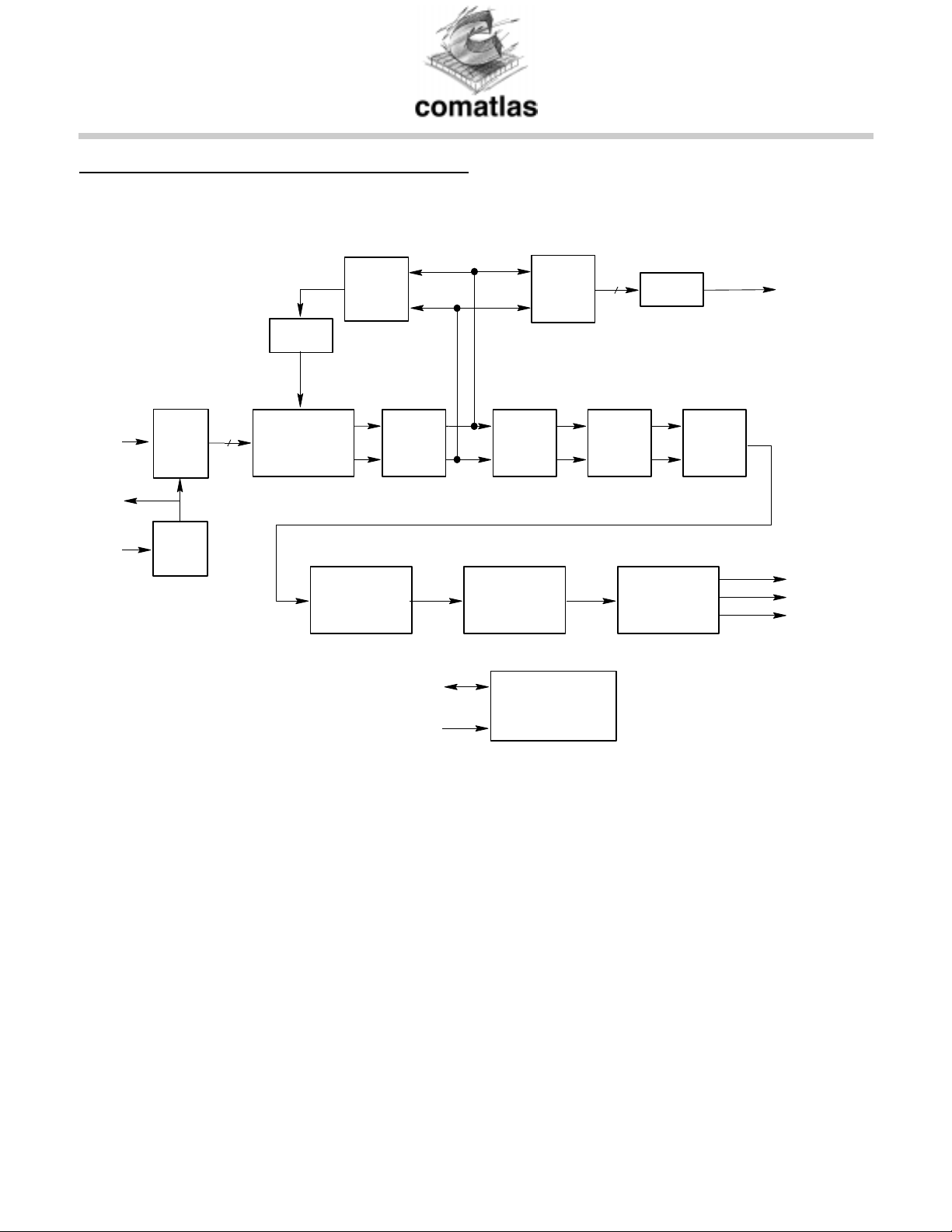
FIGURE 1 : FUNCTIONAL BLOCK DIAGRAM
IF
SACLK
XIN
ADC
PLL
9
NCO
BASE-BAND
CONVERSION
DE-INTERLEAVER
CLOCK
RECOVERY
FILTERS
BANK
SDA
SCL
EQUALIZER
R. S.
DECODER
INTERFACE
AGC TO AGC
8
CARRIER
RECOVERY
PWM
OUTPUT
INTERFACE
DO
DE-SCRAMBLER
OCLK
DEN
2
IC
comatlas reserves the right to make any change at anytime without notice. VES 1820X rev 2.0 / Mar 99 / p3
Page 4
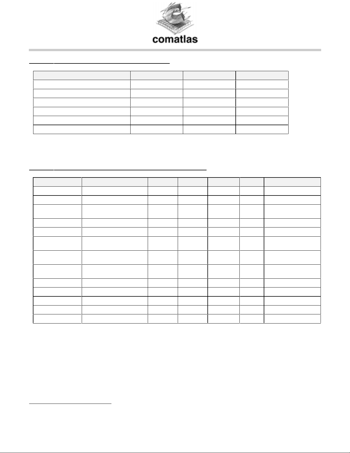
TABLE 1 : ABSOLUTE MAXIMUM RATINGS
Parameter Min Max Unit
Ambient operating temperature : Ta 0 70 °C
DC supply voltage - 0.5 + 4.1 V
DC Input voltage - 0.5 VDD + 0.5 V
DC Input Current ± 20 mA
Lead Temperature +300 °C
Junction Temperature +150 °C
Stresses above the absolute maximum ratings may cause permanent damage to the device. Exposure to absolute
maximum ratings conditions for extended periods may affect device reliability.
TABLE 2 : RECOMMENDED OPERATING CONDITIONS
Symbol Parameter Min Typ Max Unit Notes
VDD Digital supply voltage 3.14 3.3 3.46 V 3.3V ±5%
VCC 5V supply 4.75 5 5.25 V pin 17
Ta Operating temperature 0 70 °C Ambient
1
VIH
High-level input voltage 2 VCC + 0.3 V TTL input
VIL Low-level input voltage -0.5 0.8 V TTL input
2
VOH
VOL
2
High-level output
voltage
VDD -0.1
2.4
Low-level output voltage 0.1
V @ IOH = -0.8 mA
V @ IOL = 0.8 mA
0.4
IDD Supply current 200 mA @XIN = 57.84Mhz
CIN Input capacitance 15 pF
COUT Output capacitance 15 pF
VD2, VD3, VD4 Analog supply voltage 3.14 3.3 3.46 V 3.3V ± 5%
VIP Positive analog input 0.5 V
VIM Negative analog input -0.5 V
temperature
@ IOH = + 2mA
@ IOL = + 2mA
Symbol Rate =6Mbd
1
All inputs are 5V tolerant
2
IOH, IOL = ± 4mA only for pins SACLK, OCLK, SDA, CTRL1, CTRL2, IT
comatlas reserves the right to make any change at anytime without notice. VES 1820X rev 2.0 / Mar 99 / p4
Page 5
FUNCTIONAL DESCRIPTION
ADC
½
The VES1820X implements a 9-bit analog to digital converter. No external voltage references are required to use
the ADC.
PLL
½
The VES1820X implements a PLL used as clock multiplier by 1, 2, 3, 4, 5, 6, 7 or 8, so that the crystal can be
low frequency (fundamental tone).
DOWN CONVERTER AND NYQUIST FILTERS
½
The digital down converter performs the down conversion of the bandpass input signal into the 2 classical
quadrature I & Q channels. Then these two signals are passed through anti-alias filters and through a half
Nyquist filter having a fixed roll-off of 0.15. The digital filter gives a stop band attenuation of more than 40 dB.
EQUALIZER
½
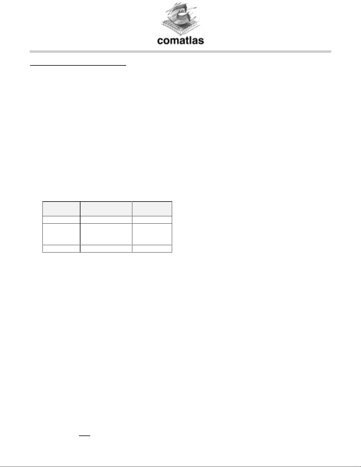
After Nyquist filtering, the signal is fed to an equalization filter, for echo cancellation. This equalizer can be
configured as either a transversal Equalizer or a decision feedback equalizer. The following table shows some
echos configuration that the VES1820X corrects with an equivalent degradation of less than 1dB @ BER = 10
-4
.
DELAY
(nS)
AMPLITUDE
(dB)
PHASE
50 -10 worst
150
and
800
-12
and
-20
worst
1600 -20 worst
CARRIER RECOVERY
½
The carrier synchronizer implements a fully digital algorithm allowing to recover carr ier frequency offsets up to
± 8 % symbol rate. A phase error detector followed by a programmable second order loop filter provides an
estimation of the carrier phase, to compensate the input carrier frequency offset.
CLOCK RECOVERY
½
A timing error detector implements an application of Gardner algorithm for digital clock recovery.
The resulting error is fed to a programmable second order loop filter, which provides a 8-bit command to the
NCO block. This one allows to determine the right sampling time instant of the input signal.
AUTOMATIC GAIN CONTROL
½
An estimation of input signal magnitude is performed and compared to a threshold value which is programmable
via the microcontroller interface. The resulting error is then filtered to produce an 10-bit command which is then
PWM encoded and provided on pin VAGC. The PWM signal can be passed through a single RC filter to control
the input gain amplifier.
½ OUTPUT INTERFACE
After carrier recovery, the demodulated output symbol must be decoded according to the constellation diagram
given by DVB standard for 16, 32, 64, 128 and 256 QAM. The resulting symbols are then differentially decoded
(DVB compliant) and serially provided to the FEC part.
½ BLOCK SYNCHRONIZATION
At demodulator output, the length of some error bursts may exceed that which can be r eliably corrected by the
Reed-Solomon decoder. The implemented de-interleaving is a convolutional one (Forney) of depth 12. The first
operation consists in synchronizing the de-interleaver. This is accomplished by detecting α consecutive MPEG2
sync words (or
sync) which are present as the first byte of each packet.
comatlas reserves the right to make any change at anytime without notice. VES 1820X rev 2.0 / Mar 99 / p5
Page 6

Next, the RAM memory associated with the deinterleaver fills up and the first deinterleaved bytes are pr ovided to
the input of the Reed-Solomon decoder. The state machine of the de-interleaver goes to the control phase which
counts β consecutive missed MPEG2 sync words (or
sync ) before declaring the system desynchronized and
going back to the synchronization phase. α and β are programmable through the I2C interface.
When the inverted sync word is detected at the input of the de-interleaver, the bytes provided to the ReedSolomon decoder are inverted at the output of the deinterleaver.
REED-SOLOMON DECODER
½
The Reed-Solomon decoder decodes the symbol stream from the de-interleaver according to the (204, 188)
shortened Reed-Solomon code. Synchronization to Reed-Solomon code is defined over the finite Galois field GF
8
). The field generator polynomial is given by :
(2
15
G(x) =
(x +α i)
π
i=0
This Reed-Solomon decoder corrects up to eight erroneous symbols in each block. When the correction
capability of the decoder is exceeded, the block is not changed and is provided as it has been entered. In this
case the flag UNCOR is set and the MSB of the second byte in the MPEG2 frame is forced to one (error
indicator). The correction capability of the RS decoder can be inhibited.
DESCRAMBLER
½
In order to comply with energy dispersal requirements of radio transmission regulations and to ensure adequate
binary transitions, the MPEG2 frames are scrambled at the encoder side. Dual operation is achieved at the
output of the Reed-Solomon decoder using the same scrambler/descrambler. The polynomial for the pseudo
random binary sequence (PRBS generator is 1 + x
14
+ x15. The PRBS registers are initialized at the start of every
eight transport packets. To provide an initialization signal for the descrambler, the MPEG2 sync byte of the first
transport packet is inverted from 47
to B816. When detected, the descrambler is loaded with the initial sequence
16
"100101010000000". The descrambler can be inhibited.
INTERFACE
½
The VES1820X integrates an I2C interface in slave mode. This I2C interface fulfills the Philips component I2C
bus specification.
comatlas reserves the right to make any change at anytime without notice. VES 1820X rev 2.0 / Mar 99 / p6
Page 7
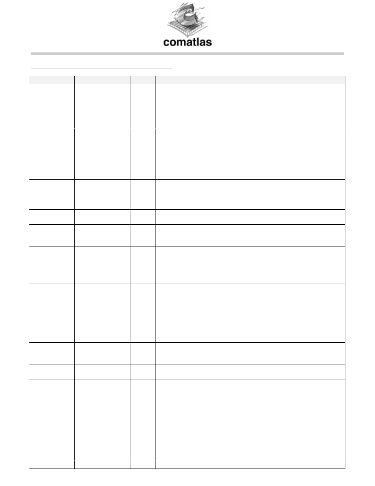
INPUT - OUTPUT SIGNAL DESCRIPTION
SYMBOL PIN NUMBER TYPE DESCRIPTION
CLR# 27 I The CLR# input is asynchronous and active low, and clears the
VES1820X. When CLR# goes low, the circuit immediately enters its
RESET mode and normal operation will resume 4 XIN falling edges
later after CLR# returned high. The I2C register contents are all
initialized to their default values. The minimum width of CLR# at low
level is 4 XIN clock periods.
XIN 2 I XTAL oscillator input pin. Typically a fundamental XTAL oscillator is
connected between the XIN and XOUT pins (see typical application
on Error! Reference source not found. page Error! Bookmark
not defined.). The XTAL frequency MUST be chosen so that the
system frequency SYSCLK (= XIN * multiplying factor of the PLL)
equals to 1.6 times the tuner output Intermediate Frequency :
SYSCLK = 1.6 x IF.
XOUT 3 O XTAL oscillator output pin. Typically a fundamental XTAL oscillator is
connected between the XIN and XOUT pins (see typical application
Error! Reference source not found. page Error! Bookmark not
defined.).
SACLK 18 O
(5V)
FI[8:0] 5,6,7,8,12,
13,14,15,16
VAGC 20 O
(5V)
DO[7:0] 46,49,50,51
52,53,54,55
(3.3V)
OCLK 44 O
(3.3V)
DEN 45 O
(3.3V)
UNCOR 42 O
(3.3V)
PSYNC 43 O
(3.3V)
TESTO[16:0] 78,77,76,75,74 O TESTO [16:0] is 17-bit Test output bus.
Sampling CLocK. This output clock can be fed to an external 9-bit
ADC as the sampling clock.SACLK = SYSCLK/2.
I FI [8:0] is the 9-bit input of the IF signal. FI[8:0] is the output of an
external A/D converter. FI[8] is the MSB. When not used, must be
tied to ground.
PWM encoded output signal for AGC. This signal is typically fed to
the AGC amplifier through a single RC network (see typical
application Error! Reference source not found. page Error!
Bookmark not defined.). The maximum signal frequency on VAGC
output is XIN/16. AGC information is refreshed every 1024 symbols.
O
Data Output bus . These 8-bit parallel data are the outputs of the
VES1820X after demodulation, de-interleaving, RS decoding and descrambling.
When one of the two possible parallel interfaces is selected
(Parameter SERINT=0, index 20
) then DO[7:0] is the transport
stream output.
When the serial interface is selected (Parameter SERINT=1, index
) then the serial output is on pin DO[0] (pin 55).
20
16
Output CLock. OCLK is the output clock for the parallel DO[7:0]
outputs. OCLK is internally generated depending on which interface
is selected.
Data ENable : this output signal is high when there is a valid data on
output bus DO[7 :0].
UNCORrectable packet. This output signal is high when the provided
packet is uncorrectable (during the 188 bytes of the packet). The
uncorrectable packet is not affected by the Reed Solomon decoder,
but the MSB of the byte following the sync. byte is forced « 1 » for
the MPEG2 process : Error Flag Indicator (if RSI and IEI are set low
in the I2C table).
Pulse SYNChro. This output signal goes high when the sync byte
) is provided, then it goes low until the next sync byte. If the
(47
serial interface is selected, then PSYNC is high only during the first
bit of the sync byte (47
). See Error! Reference source not found.
page Error! Bookmark not defined..
comatlas reserves the right to make any change at anytime without notice. VES 1820X rev 2.0 / Mar 99 / p7
Page 8
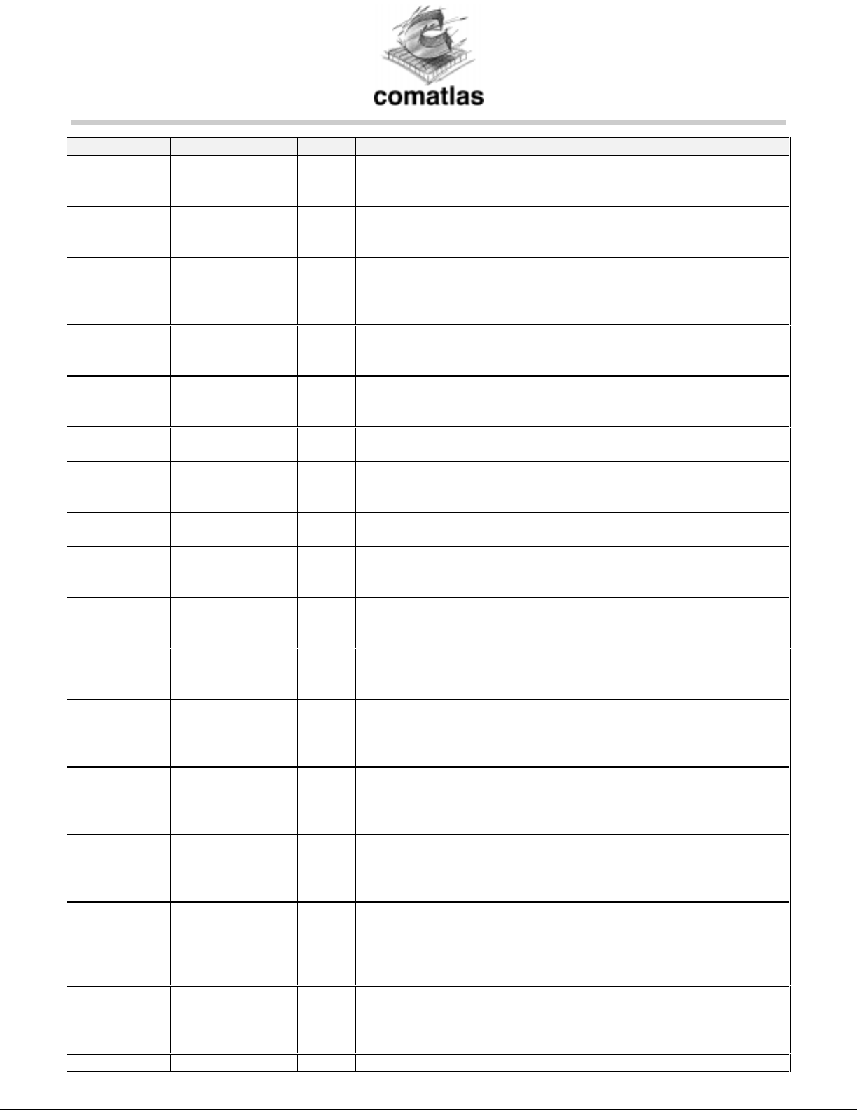
SYMBOL PIN NUMBER TYPE DESCRIPTION
71,70,69,68,67
(3.3V)
64,63,62,61,60
57,56
IICDIV[1:0] 21,22 I IICDIV[1:0] allow to select the frequency of the I2C internal system
clock, depending on the crystal frequency. Internal I2C clock is a
division of XIN by 2
IICDIV
and must be between 6 and 20 MHz.
SADDR[1:0] 23,24 I SADDR[1:0] are the 2 LSBs of the I2C address of the VES1820X.
The MSBs are internally set to 00010. Therefore the complete I2C
address of the VES1820X is (MSB to LSB) : 0, 0, 0, 1, 0, SADDR[1],
SADDR[0].
SDA 26 I/O
(5V)
SDA is a bidirectional signal. It is the serial input/output of the I2C
internal block. A pull-up resistor (typically 4.7 kΩ) must be connected
between SDA and VDD for proper operation (Open Drain output).
SCL 25 I I2C clock input. SCL should nominally be a square wave with a
maximum frequency of 400KHz. SCL is generated by the system I2C
master.
TEST 19 I Test input pin. For normal oper ation of the VES1820X, TEST must
be grounded.
TRST 35 I Test ReSeT. This active low input signal is used to reset the TAP
controller when in boundary scan mode. In normal mode of operation
TRST must be set low.
TDO 37 O
(5V)
Test Data Out. This is the serial Test output pin used in boundary
scan mode. Serial Data are provided on the falling edge of TCK.
TCK 33 I Test ClocK : an independant clock used to drive the TAP controller
when in boundary scan mode. In normal mode of operation, TCK
must be grounded.
TDI 34 I Test Data In. The serial input for Test data and instruction when in
boundary scan mode. In normal mode of operation, TDI must be set
to GND.
TMS 36 I Test Mode Select. This input signal provides the logic levels needed
to change the TAP controller from state to state. In normal mode of
operation, TMS must be set to VDD.
CTRL1 31 I/O
(5V)
CTRL1 is equivalent to SDA I/O of VES1820X but can be tri-stated
by I2C programmation. It is actually the output of a switch controlled
by parameter BYPIIC of register TEST (index 0F
). CTRL1 is open
drain output, and therefore requires an external pull up resistor.
CTRL2 32 O
(5V)
CTRL2 can be configured to be a control line output or to output SCL
input. This is controlled by parameter BYPIIC of register TEST (index
). CTRL2 is an open drain output and therefore requires an
0F
external pull up resistor.
IT 38 O
(5V)
InTerrupt line. This active low output interrupt line can be configured
by the I2C interface. See registers ITsel (index 32
(index 33
). IT is an open drain output and therefore requires an
) and ITstat
external pull up resistor.
FEL 39 O
(5V)
By default FEL is a front-end lock indicator. In this case FEL is an
open drain output and therefore requires an external pull up resistor.
But FEL can also be configured to output a PWM signal, which value
can be programmed through the I2C interface (see register
PWMREF, index 34
).
16
VIP 92 I Positive input to the A/D converter. This pin is DC biased to half-
supply through an internal resistor divider (2 x 10kΩ resistors). In
order to remain in the range of the ADC, the voltage difference
between pins VIP and VIM should be between -0.5 and 0.5 volts.
VIM 91 I Negative input to the A/D converter. This pin is DC biased to half-
comatlas reserves the right to make any change at anytime without notice. VES 1820X rev 2.0 / Mar 99 / p8
Page 9
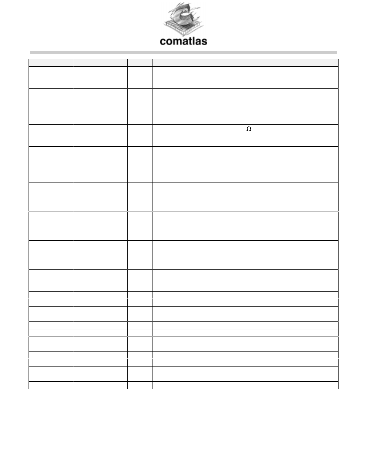
SYMBOL PIN NUMBER TYPE DESCRIPTION
supply through an internal resistor divider (2 x 10kΩ resistors). In
order to remain in the range of the ADC, the voltage difference
between pins VIP and VIM should be between -0.5 and 0.5 volts.
CMCAP 85 I This pin is connected to a tap point on an internal resistor divider
used to create CMO and CMI. An external capacitor of value 0.1µf
should be connected between this point and ground to provide good
power supply rejection from the positive supply at higher
frequencies.
RBIAS 82 I An external resistor of value 3.3k should be connected between
this pin and ground to provide good accurate bias currents for the
analog circuits on the ADC.
VREF 88 O This is the output of an on-chip resistor divider. An external capacitor
of value 0.1µf should be connected between this point and ground to
provide good power supply rejection from the positive supply at
higher frequencies. Reference voltages VREFP and VREFM are
derived from the voltage on VREF.
VREFP 87 O This is a positive voltage reference for the A/D converter. It is derived
from the voltage on pin VREF through an on-chip fully-differential
amplifier. The voltage on this pin is nominally equal to CMO + 0.25
volts.
VREFM 86 O This is the negative voltage reference for the A/D converter. It is
derived from the voltage on pin VREF through an on-chip fullydifferential amplifier. The voltage on this pin is nominally equal to
CMO- 0.25 volts.
CMO 84 O This pin provides the common-mode out voltage for the analog
circuits on the ADC. It is the buffered version of a voltage derived
from an on-chip resistor devider, and has a nominal value of 0.5 x
VD3.
CMI 83 O This pin provides the common-mode in voltage for the analog circuits
on the ADC. It is the buffered version of a voltage derived from an
on-chip resistor devider, and has a nominal value of 0.75 x VD3.
VD1 81 I Power supply input for the digital switching circuitry (3.3 typ).
VS1 80 I Ground return for the digital switching circuitry.
VD2 94 I Power supply input for the analog clock drivers (3.3V typ).
VS2 93 I Ground return for the analog clock drivers.
VD3 89 I Power supply input for the analog circuits (3.3V typ).
VS3 90 I Ground return for analog circuits.
VD4 95 I Power supply input that connects to an n-well guard ring that
surrounds the ADC (3.3V typ).
DVCC 96 I 3.3V supply for the digital section of the PLL.
DGND 97 I Ground connection for the digital section of the PLL.
PLLGND 98 I Ground connection for the analog section of the PLL.
PLLVCC 99 I 3.3V supply for the analog section of the PLL.
PPLUS 100 I P-well bias for the analog section of the PLL. Must be tied to 0V.
comatlas reserves the right to make any change at anytime without notice. VES 1820X rev 2.0 / Mar 99 / p9
Page 10
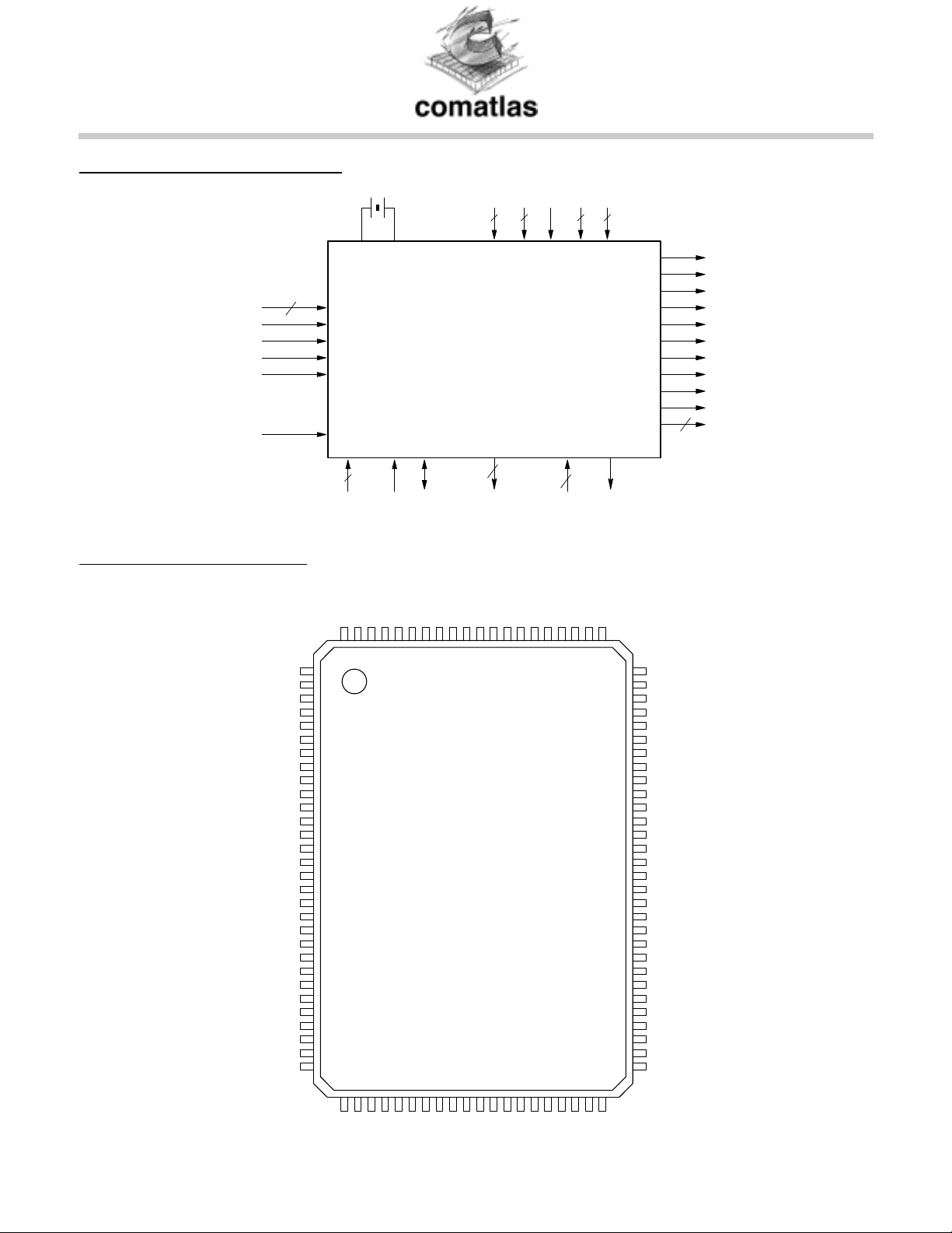
FIGURE 2 : BLOCK DIAGRAM
FI[8:0]
9
TEST
CLR#
VIP
VIM
IICDIV[1:0]
FIGURE 3 : PIN DIAGRAM
XIN XOUT
INPUTS
INTERFACE
3
SADDR[1:0] SCL SDA
PLLGND
PLLVCC
PPLUS
DVCC
DGND
VD4
VD2
VDD11GND11VCC VSi
POWER SUPPLIES
VES1820X
TEST
18
TESTO[16:0]
VREFP
VREF
VS3
VD3
VIM
VS2
VIP
VREFM
CMCAP
4
CMO
VDi
4
JTAG
CMI
4
OUTPUTS
TDO
RBIAS
VD1
SACLK
VAGC
CTRL1
CTRL2
IT
FEL
PSYNC
UNCOR
DEN
OCLK
8
DO[7:0]
VDD
XIN
XOUT
GND
FI[8]
FI[7]
FI[6]
FI[5]
VDD
GND
GND
FI[4]
FI[3]
FI[2]
FI[1]
FI[0]
VCC(5V)
SACLK
TEST
VAGC
IICDIV[1]
IICDIV[0]
SADDR[1]
SADDR[0]
SCL
SDA
CLR#
VDD
GND
GND
100
1
5
10
15
95
90
85
VES1820X
20
25
30
31
35
40
45
81
80
VS1
VS4
TESTO[16]
TESTO[15]
TESTO[14]
75
TESTO[13]
TESTO[12]
GND
VDD
TESTO[11]
70
TESTO[10]
TESTO[9]
TESTO[8]
TESTO[7]
GND
65
VDD
TESTO[6]
TESTO[5]
TESTO[4]
TESTO[3]
60
TESTO[2]
GND
VDD
TESTO[1]
TESTO[0]
55
DO[0]
DO[1]
DO[2]
DO[3]
51
DO[4]
50
VDD
CTRL2
CTRL1
TCK
TDI
TRST
TMS
TDO
GND
FEL
IT
UNCOR
PSYNC
OCLK
DEN
DO[7]
VDD
GND
DO[6]
DO[5]
comatlas reserves the right to make any change at anytime without notice. VES 1820X rev 2.0 / Mar 99 / p10
Page 11
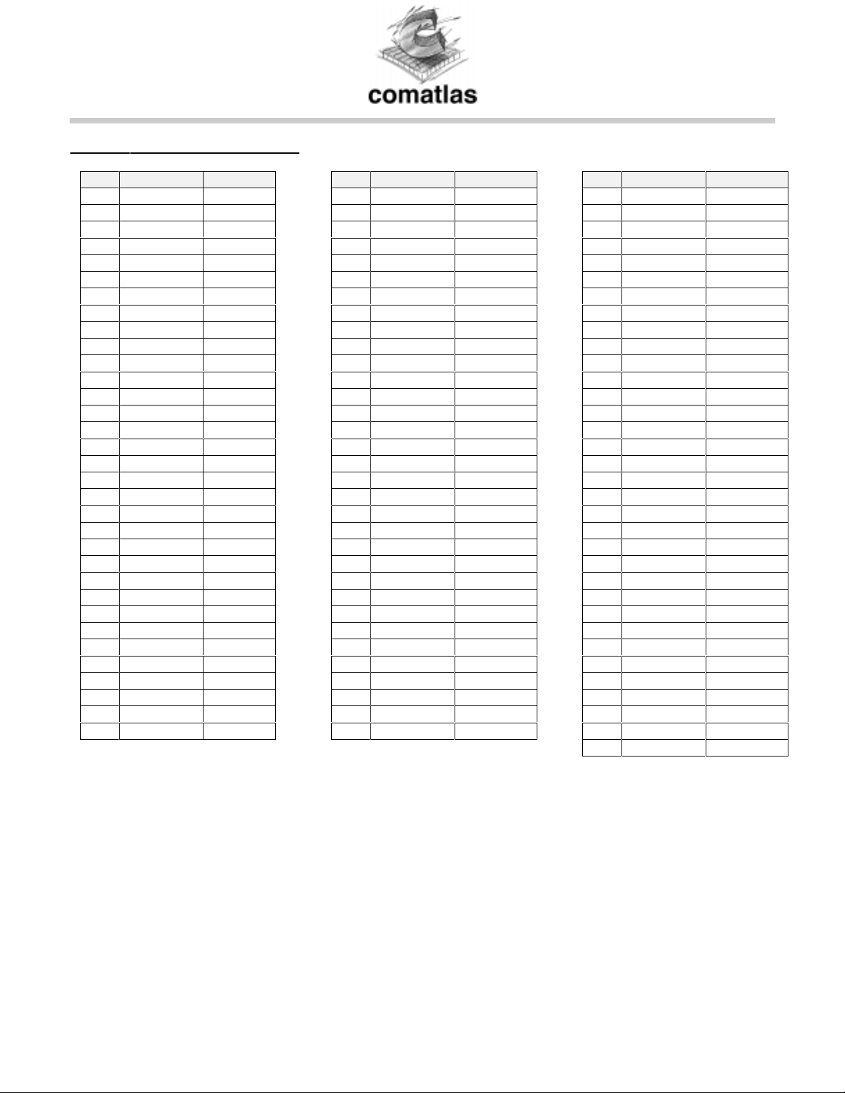
TABLE 3 : PIN DESCRIPTION
Pin Pin Name Direction
1VDD 2XIN I
3XOUT O
4GND 5 FI[8] I
6 FI[7] I
7 FI[6] I
8 FI[5] I
9VDD 10 GND 11 GND 12 FI[4] I
13 FI[3] I
14 FI[2] I
15 FI[1] I
16 FI[0] I
17 VCC 18 SACLK O
19 TEST I
20 VAGC O
21 IICDIV[1] I
22 IICDIV[1] I
23 SADDR[1] I
24 SADDR[0] I
25 SCL I
26 SDA I/O
27 CLR# I
28 VDD 29 GND 30 GND 31 CTRL1 I/O
32 CTRL2 OD
33 TCK I
Pin Pin Name Direction
34 TDI I
35 TRST I
36 TMS I
37 TDO OD
38 IT OD
39 FEL OD
40 VDD 41 GND 42 UNCOR O
43 PSYNC O
44 OCLK O
45 DEN O
46 DO[7] O
47 VDD 48 GND 49 DO[6] O
50 DO[5] O
51 DO[4] O
52 DO[3] O
53 DO[2] O
54 DO[1] O
55 DO[0] O
56 TESTO[0] O
57 TESTO[1] O
58 VDD 59 GND 60 TESTO[2] O
61 TESTO[3] O
62 TESTO[4] O
63 TESTO[5] O
64 TESTO[6] O
65 VDD 66 GND -
Pin Pin Name Direction
67 TESTO[7] O
68 TESTO[8] O
69 TESTO[9] O
70 TESTO[10] O
71 TESTO[11] O
72 VDD 73 GND 74 TESTO[12] O
75 TESTO[13] O
76 TESTO[14] O
77 TESTO[15] O
78 TESTO[16] O
79 VS4 80 VS1 81 VD1 82 RBIAS I
83 CMI O
84 CMO O
85 CMCAP I
86 VREFM O
87 VREFP O
88 VREF O
89 VD3 90 VS3 91 VIM I
92 VIP I
93 VS2 94 VD2 95 VD4 96 DVCC 97 DGND 98 PLLGND 99 PLLVCC -
100 PPLUS -
Notes :
1.All inputs (I) are TTL, 5V tolerant inputs
2.OD are Open Drain 5V outputs, so they must be connected to a pull-up resistor to either VDD or VCC
comatlas reserves the right to make any change at anytime without notice. VES 1820X rev 2.0 / Mar 99 / p11
Page 12

comatlas S.A., 30 rue du Chêne Germain, BP 814, 35518 CESSON-SEVIGNE Cedex, FRANCE
Phone : +33 (0)2 99 27 55 55, Fax : +33 (0)2 99 27 55 27 , Internet: www.comatlas.fr
comatlas reserves the right to make any change at anytime without notice.
comatlas reserves the right to make any change at anytime without notice. VES 1820X rev 2.0 / Mar 99 / p12
 Loading...