

Page 1
Distance sensor
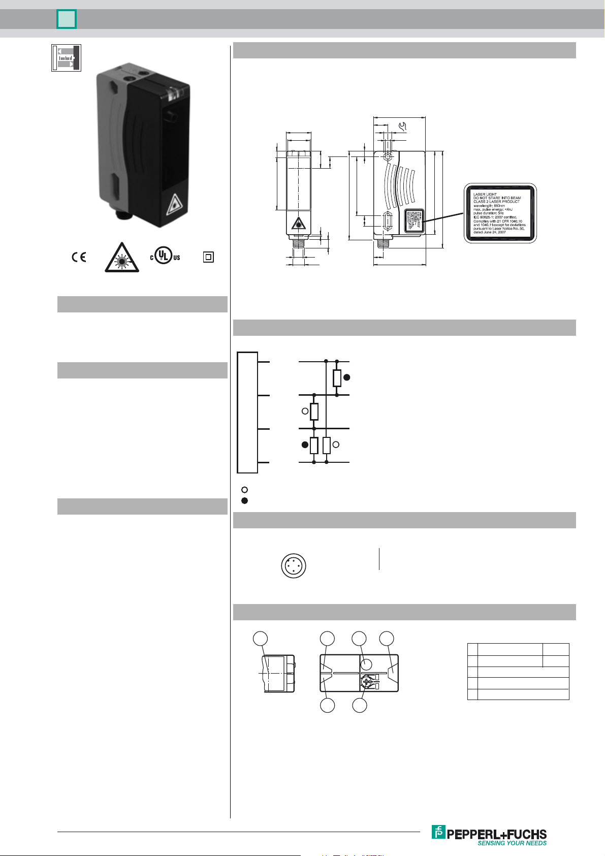
Dimensions
754.9
25.8
23.8
VDM28-8-L/73c/136
54.3
14.8
8
ø 5.2
18
12
6
Model Number
VDM28-8-L/73c/136
Distance sensor
with 4-pin, M12 x 1 connector
Features
• Distance measurement using object
• Measuring method PRT (Pulse
Ranging Technology)
• Accurate, clear, and reproducible
measuring results
• Minimal black-white difference
• Red laser as the light emitter
• Version with laser class 2
Product information
The VDM28 distance measurement device
employs Pulse Ranging Technology (PRT).
It has a repeat accuracy of 5 mm with an
operating range of 0.2 ... 8 m and an absolute
accuracy of 25 mm.
The compact housing of the Series 28
photoelectric sensors, with dimensions of
88 mm (height), 26 mm (width) and 54 mm
(depth), make it the smallest device available
in its class.
62
93
2
9
9.8
M12
11
Electrical connection
Option:
1
2
3
4
+UB
Q2
0 V
Q1
= Light on
= Dark on
Pinout
1
2
4
3
Wire colors in accordance with EN 60947-5-2
1 BN
2 WH
3 BU
4 BK
Indicators/operating means
88
102
10
54.6
(brown)
(white)
(blue)
(black)
Release date: 2017-10-16 12:24 Date of issue: 2017-10-16 217720_eng.xml
Refer to “General Notes Relating to Pepperl+Fuchs Product Information”.
2 2
35
SET
A
Q1
B
RUN
A
Q2
B
1 4
1 Operating display green
2 Signal display yellow
3 TEACH-IN button
4 Mode rotary switch
5 Laser output
1
Page 2
Distance sensor
VDM28-8-L/73c/136
Technical data
General specifications
Measurement range 0.2 ... 8 m
Reference target Kodak white (90%)
Light source laser diode
Light type modulated visible red light
Laser nominal ratings
Note LASER LIGHT , DO NOT STARE INTO BEAM
Laser class 2
Wave length 660 nm
Beam divergence 1 mrad
Pulse length 5 ns
Repetition rate 250 kHz
max. pulse energy < 4 nJ
Angle deviation max. ± 2°
Measuring method Pulse Ranging Technology (PRT)
Diameter of the light spot < 10 mm at a distance of 8 m at 20 °C
Ambient light limit 50000 Lux
Temperature influence typ. ≤ 0.25 mm/K
Functional safety related parameters
MTTFd 200 a
Mission Time (T
Diagnostic Coverage (DC) 0 %
) 10 a
M
Indicators/operating means
Operation indicator LED green
Function indicator 2 LEDs yellow for switching state
Teach-In indicator Teach-In: LED green/yellow equiphase flashing; 2.5 Hz
Control elements 5-step rotary switch for operating modes selection (threshold
Control elements Switch for setting the threshold values
Electrical specifications
Operating voltage UB10 ... 30 V DC , class 2
Ripple 10 % within the supply tolerance
No-load supply current I
Time delay before availability t
Output
Signal output 2 push-pull (4 in 1) outputs, short-circuit protected, reverse
Switching voltage max. 30 V DC
Switching current max. 100 mA
Switching frequency f 50 Hz
Response time 10 ms
Measurement accuracy
Absolute accuracy ± 25 mm
Repeat accuracy < 5 mm
Ambient conditions
Ambient temperature -30 ... 50 °C (-22 ... 122 °F)
Storage temperature -30 ... 70 °C (-22 ... 158 °F)
Mechanical specifications
Housing width 25.8 mm
Housing height 88 mm
Housing depth 54.3 mm
Degree of protection IP65
Connection 4-pin, M12 x 1 connector
Material
Housing Plastic ABS
Optical face Plastic pane
Mass 90 g
Compliance with standards and
directives
Standard conformity
Product standard EN 60947-5-2
Laser class IEC 60825-1:2007 Complies with 21 CFR 1040.10 and 1040.11
typ. service life 85,000 h at Ta = +25 °C
Teach Error:LED green/yellow non equiphase flashing; 8.0 Hz
setting and operating modes)
≤ 125 mA / 24 V DC
0
1.5 s
v
polarity protected
except for deviations pursuant to Laser Notice No. 50, dated
June 24, 2007
Laserlabel
LASER LIGHT
DO NOT STARE INTO BEAM
CLASS 2 LASER PRODUCT
WAVELENGTH: 660 nm
MAX PULSE ENERGY: < 4 nJ
PULSE DURATION: 5 ns
IEC 60825-1: 2007 CERTIFIED.
COMPLIES WITH 21 CFR 1040.10
AND 1040.11 EXCEPT FOR DEVIATIONS PURSUANT TO LASER NOTICE
NO. 50, DATED JUNE 24, 2007.
LUMIÈRE LASER
NE PAS REGARDER LE FAISCEAU
PRODUIT LASER CLASSE 2
LONGUEUR D’ONDE: 660 nm
MAX. ÉNERGIE D’IMPULSION: < 4 nJ
DURÉE D’IMPULSION: 5 ns
CERTIFIÉ CEI 60825-1: 2007.
CONFORME AUX NORMES 21 CFR
1040.10 ET 1040.11 À L’EXCEPTION
DES ÉCARTS CONFORMÉMENT
À LA NOTICE DU LASER
N° 50, DATÉE DU 24 JUIN 2007.
Accessories
OMH-05
Mounting aid for round steel ø 12 mm or
sheet 1.5 mm ... 3 mm
OMH-07
Mounting aid for round steel ø 12 mm or
sheet 1.5 mm ... 3 mm
OMH-21
Mounting bracket
OMH-22
Mounting bracket
OMH-MLV11-K
dove tail mounting clamp
OMH-RLK29-HW
Mounting bracket for rear wall mounting
OMH-RL28-C
Weld slag cover model
OMH-K01
dove tail mounting clamp
OMH-K03
dove tail mounting clamp
OMH-VDM28-01
Metal enclosure for inserting protective
panes or apertures
OMH-VDM28-02
Mounting and fine adjustment device for
sensors from the 28 series
Other suitable accessories can be found at
Approvals and certificates
Protection class II, rated voltage ≤ 250 V AC with pollution degree 1-2
UL approval cULus Listed, Class 2 Power Source, Type 1 enclosure
CCC approval CCC approval / marking not required for products rated ≤36 V
Refer to “General Notes Relating to Pepperl+Fuchs Product Information”.
according to IEC 60664-1
2
Release date: 2017-10-16 12:24 Date of issue: 2017-10-16 217720_eng.xml
Page 3

Distance sensor
Curves/Diagrams
Measuring range
Object colour
black
10 %
grey
18 %
white
90 %
VDM28-8-L/73c/136
01 2 3 4 5 6
78
Distance [m]
Preferences
Teach-In:
You can use the rotary switch to select the output Q1 or Q2 and the relevant switching threshold A or B for teaching in.
The yellow LEDs indicate the current state of the selected output.
To store a switching threshold (distance measured value), press and hold the "SET" button until the yellow and green LEDs flash in phase
(approx. 2 s). Teach-In starts when the "SET" button is released.
A successful Teach-In is indicated by rapidly alternating flashing (2.5 Hz) of the yellow and green LEDs.
An unsuccessful Teach-In is indicated by alternating flashing (8 Hz) of the yellow and green LEDs.
After an unsuccessful Teach-In, the sensor continues to operate with the previous valid setting after the relevant visual fault signal is issued.
Different switching modes can be defined by teaching in the relevant distance measured values for the switching thresholds A and B:
A leer
B
A > B
B leer
A
B > A
BA
AB
Every taught-in switching threshold can be retaught (overwritten) by pressing the SET button again.
Pressing and holding the "SET" button for > 5 s completely deletes the taught-in value. The yellow and green LEDs go out simultaneously to
indicate that this procedure has been completed.
Default setting:
In general, no switching points are set at the factory. The outputs are switched to low.
Reset to default settings:
• Set the rotary switch to the "RUN" position
• Press and hold the "SET" button until the yellow and green LEDs stop flashing in phase (approx. 10 s)
• If the green LED lights up, the procedure is complete.
Error messages:
• Short circuit: In the event of a short circuit at the sensor output, the green LED flashes with a frequency of approx. 4 Hz.
• Teach error:In the event of a teach error, the yellow and green LEDs flash alternately with a frequency of approx. 8 Hz.
Note!
The difference in the taught-in distance measured values for the switching
thresholds A and B must be greater than the switching hysteresis set in the
sensor.
On delivery, the switching hysteresis is 15 mm.
If the difference in the taught-in measured values is the same as or smaller than
the set switching hysteresis, the sensor will visually signal an unsuccessful
Teach-In. The last distance measured value that was taught in will not be adopted
by the sensor.
Select a new distance measured value for switching threshold A or B with a
greater difference between the switching thresholds.
Release date: 2017-10-16 12:24 Date of issue: 2017-10-16 217720_eng.xml
Refer to “General Notes Relating to Pepperl+Fuchs Product Information”.
Teach in this distance measured value on the sensor again.
3
Page 4

Distance sensor
VDM28-8-L/73c/136
Laser notice laser class 2
• The irradiation can lead to irritation especially in a dark environment. Do not point at people!
• Caution: Do not look into the beam!
• Maintenance and repairs should only be carried out by authorized service personnel!
• Attach the device so that the warning is clearly visible and readable.
• Caution – Use of controls or adjustments or performance of procedures other than those specified herein may result in hazardous radiation
exposure.
Refer to “General Notes Relating to Pepperl+Fuchs Product Information”.
4
Release date: 2017-10-16 12:24 Date of issue: 2017-10-16 217720_eng.xml
 Loading...