

Page 1
VB027SP
HIGH VOLTAGE IGNITION COIL DRIVER
POWER I.C.
TYPE V
VB027SP 300V 9A 130mA
■ PRIMARY COIL VOLTAGE INTERNALLY SET
■ COIL CURRENT LIMIT INTERNALLY SET
■ LOGIC LEVEL COMPATIBLE INPUT
■ DRIVING CURRENT QUASI PROPORTIONAL
cl
I
cl
I
d(on)
TO COLLECTOR CURRENT
■ DOUBLE FLAG-ON COIL CURRENT
DESCRIPTION
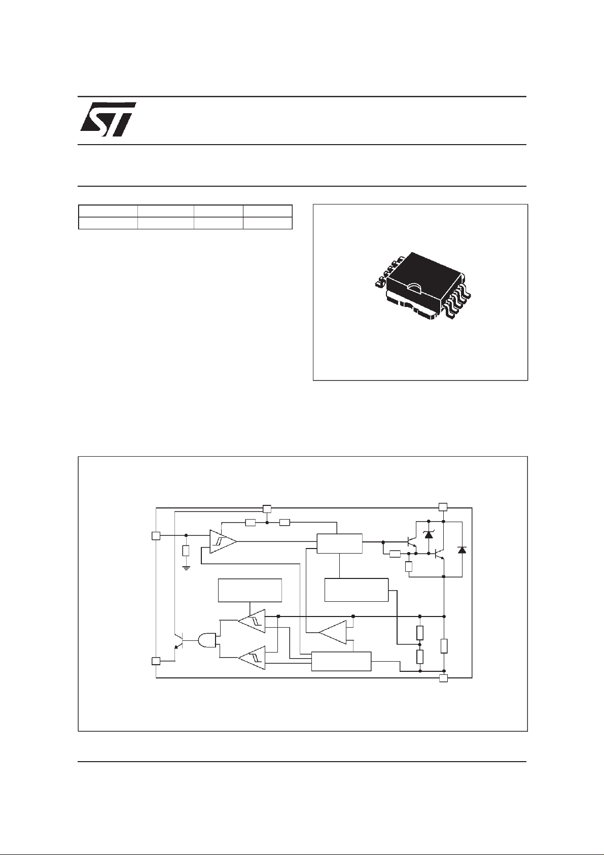
The VB027SP is a high voltage power integrated
circuit made using the STMicroelectronics
VIPower technology, with vertical current flow
power darlington and logic level compatible
driving circuit. Built-in protection circuit for coil
current limiting and collector voltage clamping
allows the device to be used as smart, high
BLOCK DIAGRAM
V
d
10
1
PowerSO-10
voltage, high current interface in advanced
electronic ignition system.
HV
C
INPUT
OVERTEMP.
PROTECTION
FLAG 1
FLAG
June 1999 1/7
FLAG 2
+
-
-
+
DRIVER
QUASI PROP.
BASE CURRENT
REFERENCE
R
SENSE
Page 2
VB027SP
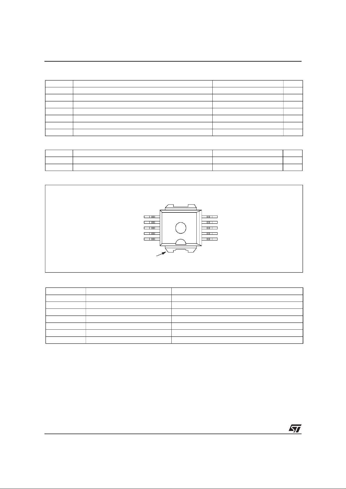
ABSOLUTE MAXIMUM RATING
Symbol Parameter Value Unit
HV
I
V
I
V
T
T
THERMAL DATA
Symbol Parameter Value Unit
R
thj-case
R
thj-amb
CONNECTION DIAGRAM (TOP VIEW)
Collector voltage Internally limited V
c
Collector current Internally limited A
C
Driving stage supply voltage 7 V
d
Driving circuitry supply current 200 mA
d
Input voltage 10 V
IN
Junction operating temperature -40 to 150 °C
j
Storage temperature -55 to 150 °C
stg
Thermal resistance junction-case (MAX) 1.12 °C/W
Thermal resistance junction-ambient (MAX) 62.5 °C/W
GND
V
d
N.C.
INPUT
DIAG
HV
6
7
8
9
10
11
C
5
4
3
2
1
PIN FUNCTION
No Name Function
1÷5 GND Emitter power ground
6(*) GND Control ground
7V
d
8 N.C.
9 INPUT Logic input channel
10 DIAG Diagnostic output signal
TAB HV
(*) Pin 1÷5=Power GND,Pin 6=signal GND. Pin 6 mustbe connected to pins 1÷5 externally.
C
Driving stage supply voltage
Primary coil output signal
GND
GND
GND
GND
GND
2/7
1
Page 3
VB027SP
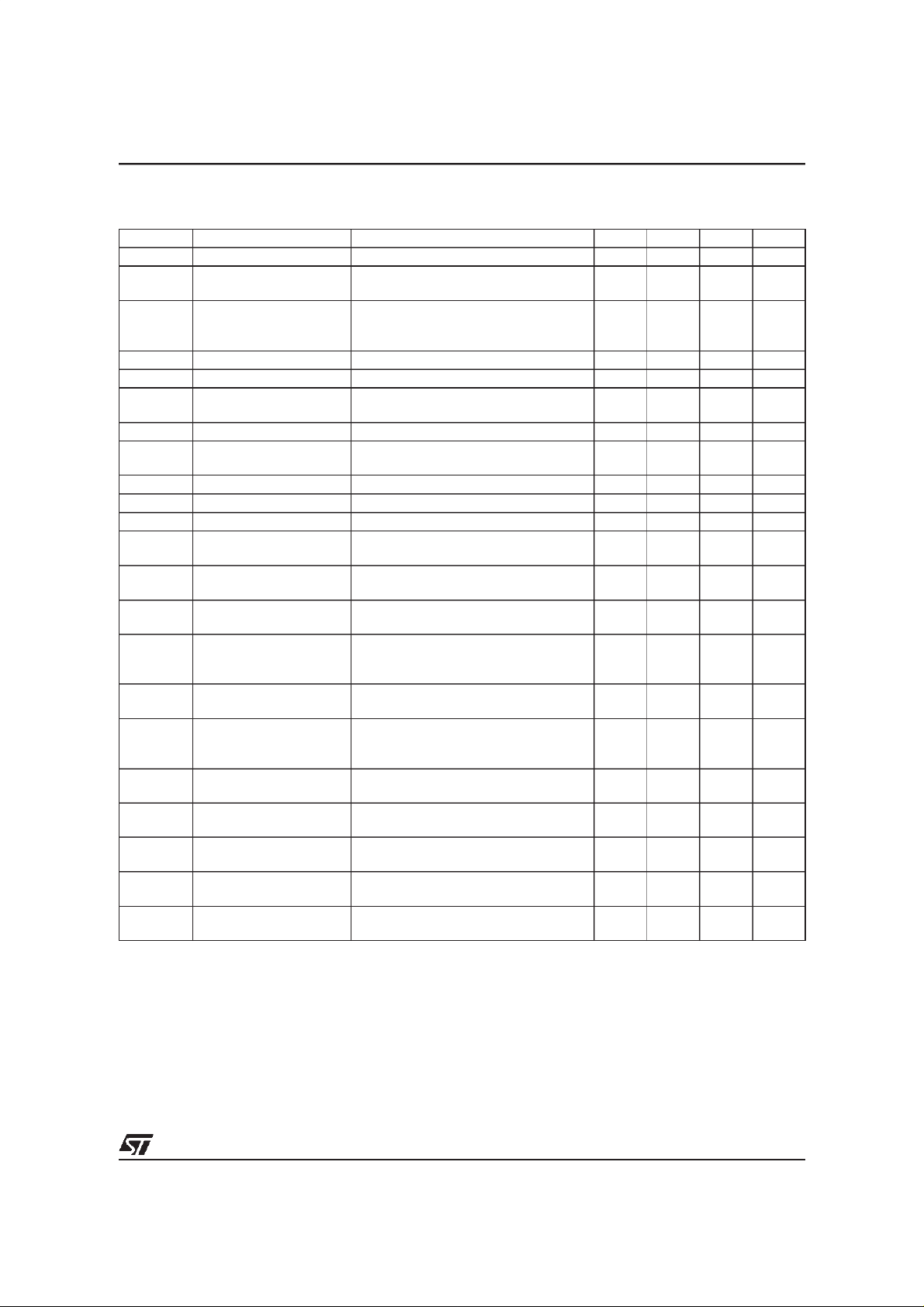
ELECTRICAL CHARACTERISTICS (V
specified)
=13.5V; Vd=5V; Tj=25ºC; R
CC
coil
=510m
Ω;
L
=7mH unless otherwise
coil
Symbol Parameter Test Conditions Min Typ Max Unit
V
V
cg(sat)
V
cg(sat)td
I
d(off)
I
d(on)
V
I
I
cl(td)
V
INH
V
INL
I
INH
V
diagH
V
diagL
I
C(diag1)
High voltage clamp VIN=0.4V; -40°C≤Tj≤125°C; IC=6A 300 360 400 V
cl
Power stage saturation
voltage
Power stage saturation
voltage derating in
temperature
IC=6A; VIN=4V; Id=80mA 1.5 V
IC=6A; VIN=4V; -40°C≤Tj≤125°C;
Id=85mA
Power-off supply current VIN=0.4V 8 mA
Power-on supply current VIN=4V; IC=6A; -40°C≤Tj≤125°C 130 mA
Driving stage supply
d
voltage
Collector current limit VIN=4V (See note 1) 8 8.5 9 A
cl
Collector current limit drift
with temperature
See figure 3
4.5 5.5 V
High level input voltage HVC<2V 4 5.5 V
Low level input voltage IC<2mA; HVC=V
CC
0 0.8 V
High level input current VIN=4V 40 200 µA
High level diagnostic
output voltage
Low level diagnostic
output voltage
First threshold level
collector current
R
=22KΩ (See figure 1) 3.5 (*) V
EXT
R
=22KΩ (See figure 1) 0.5 V
EXT
4.25 4.5 4.75 A
2V
d
First threshold level
I
C(diag1)td
collector current drift with
See figure 4
temperature
I
C(diag2)
Second threshold level
collector current
5.45 5.8 6.15 A
Second threshold level
I
C(diag2)td
t
d(off)
t
f(off)
t
d(diag)
t
r(diag)
t
f(diag)
collector current drift with
temperature
Turn-off delay time of
output current
Turn-off fall time of output
current
Delay time of diagnostic
current
Turn-on rise time of
diagnostic current
Turn-off fall time of
diagnostic current
See figure 5
IC=5.5A 25 µs
=5.5A 8 µs
I
C
R
=22KΩ (See figure 1) 1 µs
EXT
R
=22KΩ (See figure 1) 1 µs
EXT
R
=22KΩ (See figure 1) 1 µs
EXT
V
Note 1: theprimary coil current value Iclmust be measured 1ms after desaturation of the power stage.
(*) Vd-V
be(on)
3/7
1
Page 4
VB027SP
PRINCIPLE OF OPERATION
The VB027SP is mainly intended as high voltage power
switch device driven by a logic level input and interfaces
directly to a high energy electronic ignition coil.
The input V
signal generatedby an external controller thatdetermines
both dwell time and ignition point. During V
the VB027SP increases current in the coil to the desired,
of the VB027SP is fed from a low power
IN
high (≥4V)
IN
internally set current level.
When the collector current exceeds 4.5A, the diagnostic
signal is turned high and it remains so, until the load
current reaches 5.8A (second threshold). At that value,
the diagnostic signal is turned low, and the µC forces the
V
to the low state. During the coilcurrent switch-off, the
IN
primary voltage HV
diodes at an internally set value V
The collector current sensed throughthe R
thanks to the “Current limiter” blockthat, as soon as theI
is clamped by a series of Zener
C
, typically 360V.
cl
sense
, is limited
level is reached, forces the darlington (using the “Driver”
block) to limit the current provided.
The transition from saturation to desaturation, coil current
limiting phase, must have the ability to accommodate an
overvoltage. A maximum overshoot of 20V is allowed.
There can be some short period of time in which the
output pin (HV
current due to leakage inductances and stray
) is pulled below ground by a negative
C
capacitances of the ignition coil. This can cause parasitic
glitches on the diagnostic output. VB027SP has a built-in
protection circuit that allows to lock the p-buried layer
potential of the linear stage to the collector power, when
the last one is pulled underground.
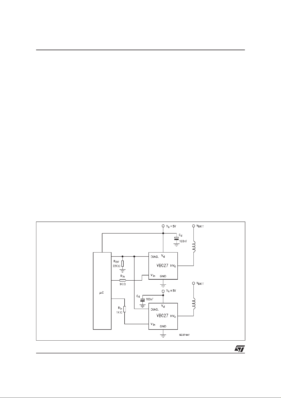
FIGURE 1: Application circuit
THERMAL BEHAVIOUR
You can see in the block diagram of theVB027SPa box
called overtemperature protection. The purpose of this
circuit is to shift the current level at which the first
diagnostic is activateddown of about 1A.
This information can be managed by the micro that can
take the corrective action in order to reduce the power
dissipation. This block is not an effective protection but
just an overtemperature detection. The shift down of the
first flag level cannot be present for temperatures lower
than 125°C.
As an example of its behavior you can suppose a very
simple motor management system in which the micro
does just a simple arithmeticcalculation to decidewhento
switch-off the device after the first flag threshold.
EXAMPLE:
I
C(DIAG1)
cl
I
switch-off
info after x ms (I
info after kx ms.
C(DIAG1)
=2.5A)
As soon as the temperature rises over the overtemp
threshold, the first diagnostic is shifted down to about
1.5A and, in this example, the switch-off current will be
kx*1.5 / 2.5.
OVERVOLTAGE
The VB027SP can withstand the following transients of
the battery line:
-100V /2ms (R
+100V / 0.2ms (R
+50V / 400ms (R
=10Ω)
i
=10Ω)
i
=4.2 Ω, with VIN=3V)
i
4/7
1
Page 5
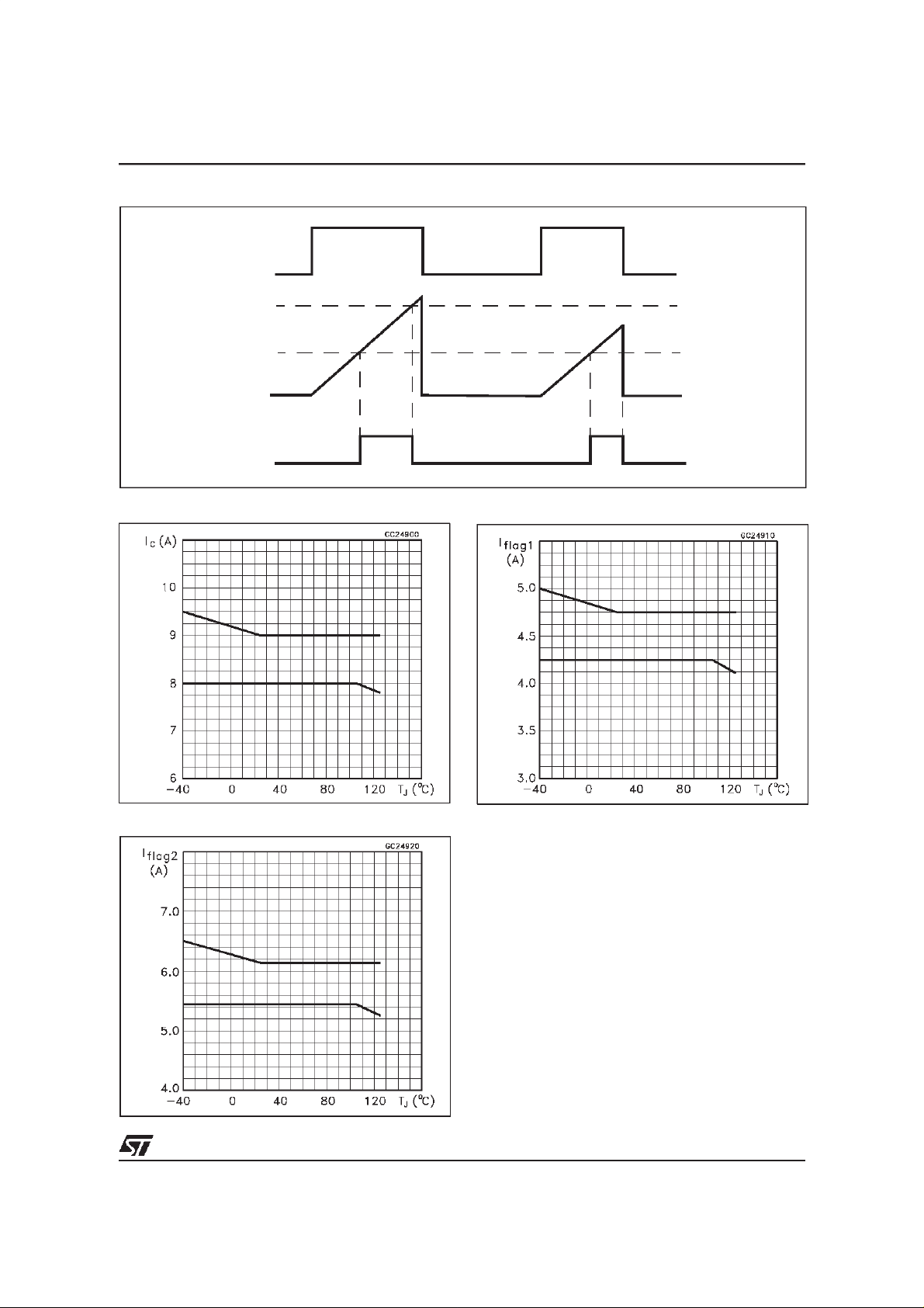
FIGURE 2: Switching waveform
V
IN
2ndThreshold
st
1
Threshold
I
cl
DIAG
VB027SP
FIGURE 3: Maximum IclVS temperature
FIGURE 5: I
C(diag2)
VS temperature
FIGURE 4: I
C(diag1)
VS temperature
5/7
1
1
Page 6
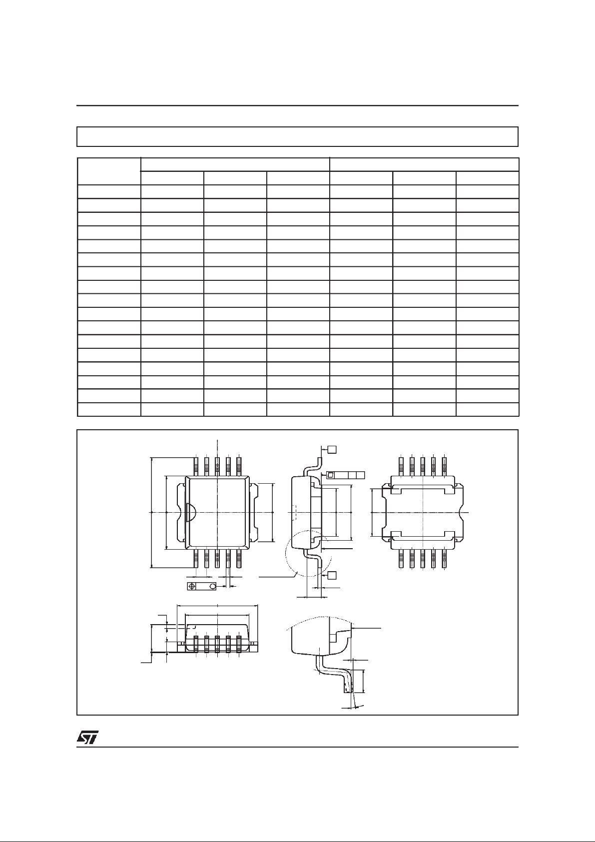
PowerSO-10 MECHANICAL DATA
VB027SP
DIM.
MIN. TYP MAX. MIN. TYP. MAX.
mm. inch
A 3.35 3.65 0.132 0.144
A1 0.00 0.10 0.000 0.004
B 0.40 0.60 0.016 0.024
c 0.35 0.55 0.013 0.022
D 9.40 9.60 0.370 0.378
D1 7.40 7.60 0.291 0.300
E 9.30 9.50 0.366 0.374
E1 7.20 7.40 0.283 0.291
E2 7.20 7.60 0.283 300
E3 6.10 6.35 0.240 0.250
E4 5.90 6.10 0.232 0.240
e 1.27 0.050
F 1.25 1.35 0.049 0.053
H 13.80 14.40 0.543 0.567
h 0.50 0.002
Q 1.70 0.067
α 0º 8º
B
B
Q
0.10 A
E1E3
==
SEATING
PLANE
A
C
α
E4
==
SEATING
PLANE
A1
L
==
==
==
HE
h
A
F
A1
610
51
eB
M
0.25
D
==
D1
==
E2
==
DETAIL”A”
DETAIL”A”
6/7
1
Page 7

VB027SP
Information furnished is believed to be accurate and reliable. However, STMicroelectronics assumes no responsibility for the consequences
of use of such information nor for any infringement of patents or other rights of third parties which may results from its use. No license is
granted by implication or otherwise under any patent or patent rights of STMicroelectronics. Specifications mentioned in this publication are
subject tochange without notice. This publicationsupersedes and replaces all information previously supplied. STMicroelectronics products
are not authorized for useascritical components in life support devices or systems without express written approval of STMicroelectronics.
Australia - Brazil - Canada - China - France - Germany - Italy - Japan - Korea - Malaysia - Malta - Mexico - Morocco -
The Netherlands- Singapore - Spain - Sweden - Switzerland - Taiwan - Thailand - United Kingdom - U.S.A.
The ST logo is a registered trademark of STMicroelectronics
1998 STMicroelectronics - Printed in ITALY- All Rights Reserved.
STMicroelectronics GROUP OF COMPANIES
7/7
 Loading...