

Page 1
ZA Series
[ /Title
(ZA
Series)
/Subject
(Radial
Lead
MetalOxide
Varistors for
Low to
Mediu
m Voltage
Operation)
/Autho
r ()
/Keywords
(Littelfuse,
Inc.,
Suppression
Products,
TVS,
Transient
Suppression,
Protection,
Automotive,
Data Sheet July 1999
Radial Lead Metal-Oxide Varistors for Low
to Medium Voltage Operation
The ZA Series of transient voltage surge suppressors are
radial-lead varistors (MOVs) designed for use in the
protection of low and medium-voltage circuits and systems.
Typical applications include motor control, telecom,
automotive systems, solenoid, and power supply circuits to
protect circuit board components and maintain data integrity.
These devices are available in five model sizes: 5mm, 7mm,
10mm, 14mm and 20mm, and feature a wide V
range of 5.5V to 615V.
See ZA Series Device Ratings and Specifications table for
part number and brand information.
voltage
DC
File Number 2184.6
Features
• Recognized as “Protectors for Data Communications and
Fire Alarm Circuits”, UL File #E135010 to Std. 497B
• VDE Certified. License Number 116895E
• Wide Operating Voltage Range V
• DC Voltage Ratings . . . . . . . . . . . . . . . . . . . 5.5V to 615V
• No Derating Up to 85
• 5 Model Sizes Available . . . . . . . . 5, 7, 10, 14, and 20mm
• Radial-Lead Package for Hard-Wired or Printed Circuit
Board Designs
• Available in Tape and Reel or Bulk Pack
• Standard Lead Form Options
o
C Ambient
M(AC)RMS
. . . . 4V to 460V
Packaging
14MM, 20MM
5MM, 7MM, 10MM
4-34
1-800-999-9445 or 1-847-824-1188
|
Copyright
Littelfuse, Inc. 1999
©
Page 2
ZA Series
Absolute Maximum Ratings
For ratings of individual members of a series, see Device Ratings and Specifications chart.
ZA SERIES UNITS
Continuous:
Steady State Applied Voltage:
AC Voltage Range (V
DC Voltage Range (V
M(AC)RMS
M(DC)
) . . . . . . . . . . . . . . . . . . . . . . . . . . . . . . . . . . . . . . . . . . . . . . . . . . . . .
) . . . . . . . . . . . . . . . . . . . . . . . . . . . . . . . . . . . . . . . . . . . . . . . . . . . . . . . .
4 to 460
5.5 to 615
V
V
Transient:
Peak Pulse Current (I
For 8/20 µ s Current Wave (See Figure 2) . . . . . . . . . . . . . . . . . . . . . . . . . . . . . . . . . . . . . . . . . . . . . . .
TM
)
50 to 6500
A
Single Pulse Energy Range (Note 1)
For 10/1000 µ s Current Wave (W
Operating Ambient Temperature Range (T
Storage Temperature Range (T
Temperature Coefficient ( α V) of Clamping Voltage (V
) . . . . . . . . . . . . . . . . . . . . . . . . . . . . . . . . . . . . . . . . . . . . . . . . . .
TM
) . . . . . . . . . . . . . . . . . . . . . . . . . . . . . . . . . . . . . . . . . . . . . . -55 to 85
A
) . . . . . . . . . . . . . . . . . . . . . . . . . . . . . . . . . . . . . . . . . . . . . . . . . . . . -55 to 125
STG
) at Specified Test Current . . . . . . . . . . . . . . . . . <0.01 %/
C
0.1 to 52
J
o
C
o
C
o
C
Hi-Pot Encapsulation (Isolation Voltage Capability) . . . . . . . . . . . . . . . . . . . . . . . . . . . . . . . . . . . . . . . . . 2500 V
(Dielectric must withstand indicated DC voltage for one minute per MIL-STD 202, Method 301) . . . .
Insulation Resistance. . . . . . . . . . . . . . . . . . . . . . . . . . . . . . . . . . . . . . . . . . . . . . . . . . . . . . . . . . . . . . . . 1000 M Ω
CAUTION: Stresses above those listed in “Absolute Maximum Ratings” may cause permanent damage to the device. This is a stress only rating and operation of the
device at these or any other conditions above those indicated in the operational sections of this specification is not implied..
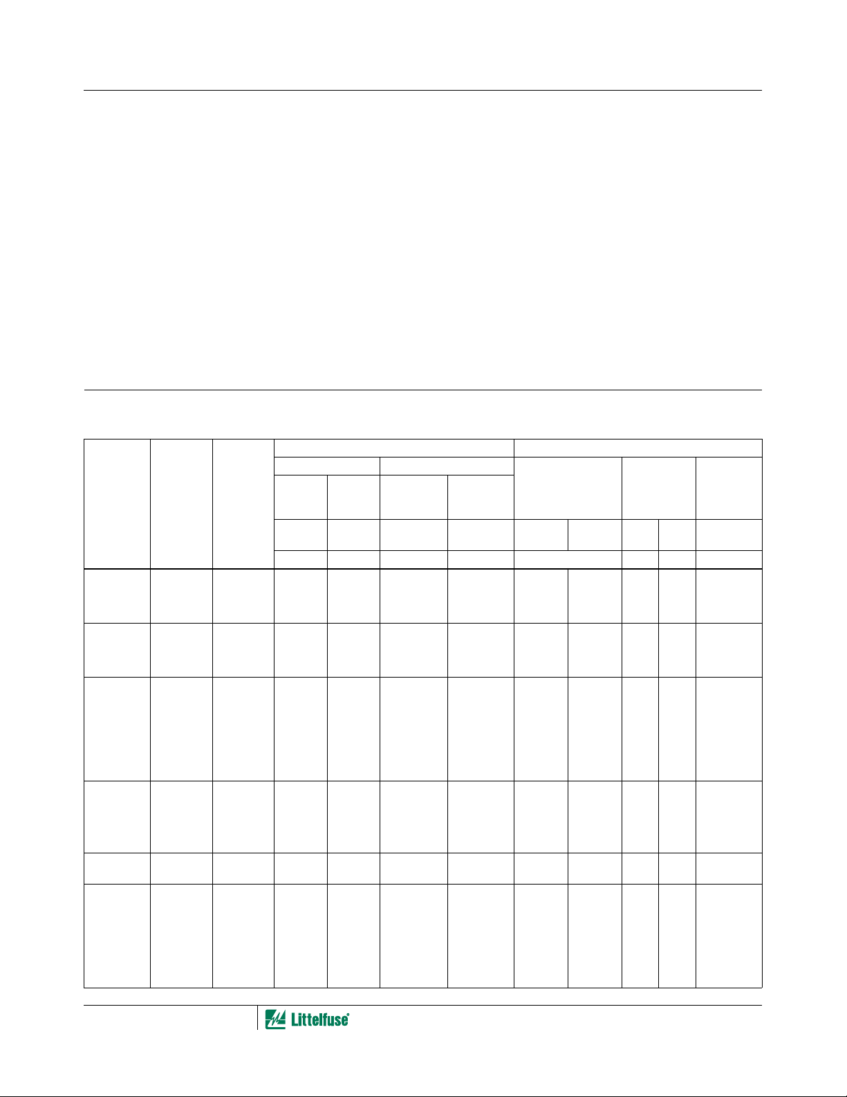
Device Ratings and Specifications
(Note 1)
VDE Certified. License Number 116895E
ZA Series Varistors are listed under UL File No. E135010 as a UL recognized component.
PART
NUMBER
MODEL
SIZE
DISC
DIA. (mm) BRAND
MAXIMUM RATING (85
CONTINUOUS TRANSIENT
ENERGY 10
V
M(AC)
RMS
V
V
M(DC)
DC
x 1000 µ s
o
C) SPECIFICATIONS (25
MAXIMUM
PEAK
CURRENT
8 x 20 µ s
W
TM
I
TM
VARISTOR VOLT-
AGE AT 1mA DC
TEST CURRENT
V
MIN
NOM
V
NOM
MAX V
CLAMPING
VOLTAGE
8 x 20 µ s
C
(V) (V) (J) (A) (V) (V) (A) (pF)
o
C)
TYPICAL
CAPACI-
TANCE
f = 1MHzV
I
PK
C
V8ZA05 5 Z08 4 5.5 0.1 50 6 11 30 1 1400
V8ZA1 7 08Z1 4 5.5 0.4 100 6 11 22 2.5 3000
V8ZA2 10 08Z2 4 5.5 0.8 250 6 11 20 5 7500
V12ZA05 5 Z12 6 8 0.14 50 9 16 37 1 1200
V12ZA1 7 12Z1 6 8 0.6 100 9 16 34 2.5 2500
V12ZA2 10 12Z2 6 8 1.2 250 9 16 30 5 6000
V18ZA05 5 Z18 10 14 0.17 100 14.4 21.6 36 1 1000
V18ZA1 7 18Z1 10 14 0.8 250 14.4 21.6 36 2.5 2000
V18ZA2 10 18Z2 10 14 1.5 500 14.4 21.6 36 5 5000
V18ZA3 14 18Z3 10 14 3.5 1000 14.4 21.6 36 10 11000
V18ZA40 20 18Z40 10 14 80 (Note 2) 2000 14.4
21.6 37 20 22000
(Note 3)
V22ZA05 5 Z22 14 18 0.2 100 18.7 26 43 1 800
V22ZA1 7 22Z1 14 18 0.9 250 18.7 26 43 2.5 1600
V22ZA2 10 22Z2 14 18 2 500 18.7 26 43 5 4000
V22ZA3 14 22Z3 14 18 4 1000 18.7 26 43 10 9000
V24ZA50 20 24Z50 14 18
(Note 4)
100 (Note 2) 2000 19.2
(Note 3)
26 43 20 18000
V27ZA05 5 Z27 17 22 0.25 100 23 31.1 53 1 600
V27ZA1 7 27Z1 17 22 1 250 23 31.1 53 2.5 1300
V27ZA2 10 27Z2 17 22 2.5 500 23 31.1 53 5 3000
V27ZA4 14 27Z4 17 22 5 1000 23 31.1 53 10 7000
V27ZA60 20 27Z60 17 22 120 (Note 2) 2000 23
31.1 50 20 13000
(Note 3)
4-35
Page 3
ZA Series
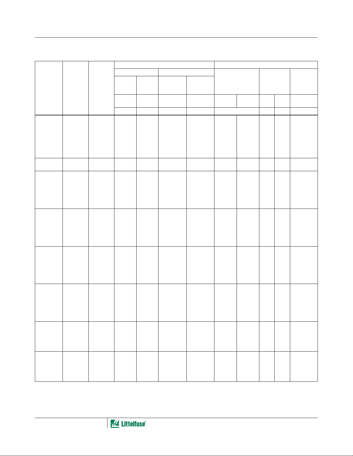
Device Ratings and Specifications
(Note 1) (Continued)
VDE Certified. License Number 116895E
ZA Series Varistors are listed under UL File No. E135010 as a UL recognized component.
PART
NUMBER
MODEL
SIZE
DISC
DIA. (mm) BRAND
MAXIMUM RATING (85
CONTINUOUS TRANSIENT
ENERGY 10
V
M(AC)
RMS
V
V
M(DC)
DC
x 1000 µ s
o
C) SPECIFICATIONS (25
MAXIMUM
PEAK
CURRENT
8 x 20 µ s
W
TM
I
TM
VARISTOR VOLT-
AGE AT 1mA DC
TEST CURRENT
V
MIN
NOM
V
NOM
MAX V
CLAMPING
VOLTAGE
8 x 20 µ s
C
(V) (V) (J) (A) (V) (V) (A) (pF)
o
C)
TYPICAL
CAPACI-
TANCE
f = 1MHzV
I
PK
V33ZA05 5 Z33 20 26 0.3 100 29.5 38 65 1 500
V33ZA1 7 33Z1 20 26 1.2 250 29.5 36.5 65 2.5 1100
V33ZA2 10 33Z2 20 26 3 500 29.5 36.5 65 5 2700
V33ZA5 14 33Z5 20 26 6 1000 29.5 36.5 65 10 6000
V33ZA70 20 33Z70 21 27 150 (Note 2) 2000 29.5
36.5 58 20 13000
(Note 3)
V36ZA80 20 36Z80 23 31 160 (Note 2) 2000 32
40 63 20 12000
(Note 3)
V39ZA05 5 Z39 25 31 0.3 100 35 46 79 1 500
V39ZA1 7 39Z1 25 31 1.2 250 35 43 79 2.5 1100
V39ZA3 10 39Z3 25 31 3 500 35 43 76 5 2700
V39ZA6 14 39Z6 25 31 6 1000 35 43 76 10 6000
V39ZA20 20 39Z20 25 31 20 2000 35 43 76 20 12000
V47ZA05 5 Z47 30 38 0.4 100 42 55 93 1 400
V47ZA1 7 47Z1 30 38 1.8 250 42 52 93 2.5 800
V47ZA3 10 47Z3 30 38 4.5 500 42 52 93 5 2000
V47ZA7 14 47Z7 30 38 8.8 1000 42 52 93 10 4500
V47ZA20 20 47Z20 30 38 23 2000 42 52 93 20 11000
V56ZA05 5 Z56 35 45 0.5 100 50 66 110 1 360
V56ZA2 7 56Z2 35 45 2.3 250 50 62 110 2.5 700
V56ZA3 10 56Z3 35 45 5.5 500 50 62 110 5 1800
V56ZA8 14 56Z8 35 45 10 1000 50 62 110 10 3900
V56ZA20 20 56Z20 35 45 30 2000 50 62 110 20 10000
V68ZA05 5 Z68 40 56 0.6 100 61 80 135 1 300
V68ZA2 7 68Z2 40 56 3 250 61 75 135 2.5 600
V68ZA3 10 68Z3 40 56 6.5 500 61 75 135 5 1500
V68ZA10 14 68Z10 40 56 13 1000 61 75 135 10 3300
V68ZA20 20 68Z20 40 56 33 2000 61 75 135 20 10000
V82ZA05 5 Z82 50 68 2 400 73 97 135 5 240
V82ZA2 7 82Z2 50 68 4 1200 73 91 135 10 500
V82ZA4 10 82Z4 50 68 8 2500 73 91 135 25 1100
V82ZA12 14 82Z12 50 68 15 4500 73 91 145 50 2500
V100ZA05 5 Z100 60 81 2.5 400 90 117 165 5 180
V100ZA3 7 100Z 60 81 5 1200 90 110 165 10 400
V100ZA4 10 100Z4 60 81 10 2500 90 110 165 25 900
V100ZA15 14 100Z15 60 81 20 4500 90 110 175 50 2000
C
4-36
Page 4
ZA Series
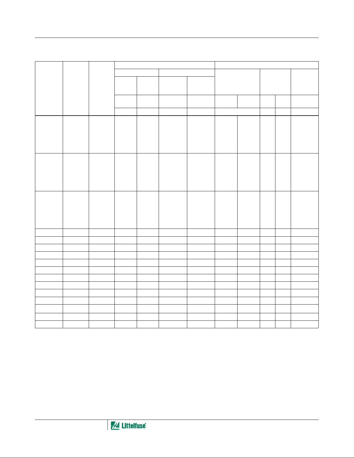
Device Ratings and Specifications
VDE Certified. License Number 116895E
ZA Series Varistors are listed under UL File No. E135010 as a UL recognized component.
MODEL
PART
NUMBER
V120ZA05 5 Z120 75 102 3 400 108 138 205 5 140
V120ZA1 7 120Z 75 102 6 1200 108 132 205 10 300
V120ZA4 10 120Z4 75 102 12 2500 108 132 200 25 750
V120ZA6 14 120Z6 75 102 22 4500 108 132 210 50 1700
V120ZA20 20 120Z20 75 102 33 6500 108 132 210 100 1500
V150ZA05 5 Z150 92 127 4 400 135 173 250 5 120
V150ZA1 7 Z051 95 127 8 1200 135 165 250 10 250
V150ZA4 10 150Z4 95 127 15 2500 135 165 250 25 600
†
V150ZA8 14 150Z8 95 127 20 4500 135 165 250 50 1400
V150ZA20 20 150Z20 95 127 45 6500 135 165 250 100 1000
V180ZA05 5 Z180 110 153 5 400 162 207 295 5 100
V180ZA1 7 180Z 115 153 10 1200 162 198 300 10 200
V180ZA5 10 180Z5 115 153 18 2500 162 198 300 25 500
V180ZA10 14 180Z10 115 153 35 4500 162 198 300 50 1100
V180ZA20 20 180Z20 115 153 52 6500 162 198 300 100 2400
V205ZA05 5 Z205 130 170 5.5 400 184 226 340 5 100
†
V220ZA05 5 Z220 140 180 6 400 198 253 360 5 90
†
V240ZA05 5 Z240 150 200 7 400 216 264 395 5 80
†
V270ZA05 5 Z270 175 225 7.5 400 243 311 455 5 70
†
V330ZA05 5 Z330 210 275 9 400 297 380 540 5 60
†
V360ZA05 5 Z360 230 300 9.5 400 324 396 595 5 55
†
V390ZA05 5 Z390 250 330 10 400 351 449 650 5 50
†
V430ZA05 5 Z430 275 369 11 400 387 495 710 5 45
†
V470ZA05 5 Z470 300 385 12 400 420 517 775 5 35
†
V620ZA05 5 Z620 385 505 13 400 558 682 1025 5 33
V680ZA05 5 Z680 420 560 14 400 610 748 1120 5 32
†
V715ZA05 5 Z715 440 585 15.5 400 643 787 1180 5 31
V750ZA05 5 Z750 460 615 17 400 675 825 1240 5 30
NOTES:
1. Average power dissipation of transients not to exceed 0.2W, 0.25W, 0.4W, 0.6W or 1W for model sizes 5mm, 7mm, 10mm, 14mm and 20mm,
respectively.
2. Energy rating for impulse duration of 30ms minimum to one half of peak current (auto load dump).
3. 10mA DC test current.
4. Also rated to withstand 24V for 5 minutes.
5. Higher voltages available, contact Littelfuse.
Also listed to UL1449, Second Edition, “Transient Voltage Surge Suppressors” File #E75961.
†
SIZE
DISC
DIA. (mm) BRAND
(Note 1) (Continued)
MAXIMUM RATING (85
CONTINUOUS TRANSIENT
DC
ENERGY 10
x 1000 µ s
RMS
V
M(AC)
(V) (V) (J) (A) (V) (V) (A) (pF)
V
V
M(DC)
o
C) SPECIFICATIONS (25
PEAK
CURRENT
8 x 20 µ s
W
TM
I
TM
VARISTOR VOLT-
AGE AT 1mA DC
TEST CURRENT
V
MIN
NOM
V
NOM
MAX V
MAXIMUM
CLAMPING
VOLTAGE
8 x 20 µ s
C
o
C)
TYPICAL
CAPACI-
I
PK
TANCE
f = 1MHzV
C
4-37
Page 5

ZA Series
Power Dissipation Ratings
Should transients occur in rapid succession, the average
power dissipation required is simply the energy (wattseconds) per pulse times the number of pulses per second.
The power so developed must be within the specifications
shown on the Device Ratings and Specifications table for the
specific device. Furthermore, the operating values need to
be derated at high temperatures as shown in Figure 1.
Because varistors can only dissipate a relatively small
amount of average power they are, therefore, not suitable for
repetitive applications that involve substantial amounts of
average power dissipation.
100
90
50
PERCENT OF PEAK VALUE
10
O
1
T
T
1
T
2
TIME
1.
100
90
80
70
60
50
40
30
20
PERCENT OF RATED VALUE
10
0
-55 50 60 70 80 90 100 110 120 130 140 150
AMBIENT TEMPERATURE (
FIGURE 1. CURRENT, ENERGY AND POWER DERATING
CURVE
O1 = Virtual Origin of Wave
T = Time From 10% to 90% of Peak
T1 = Virtual Front time = 1.25 • t
T2 = Virtual Time to Half Value (Impulse Duration)
Example: For an 8/20µs Current Waveform:
8µs = T1 = Virtual Front Time
20µs = T2 = Virtual Time to Half Value
o
C)
FIGURE 2. PEAK PULSE CURRENT TEST WAVEFORM
Transient V-I Characteristics Curves
600
MAX CLAMPING VOLTAGE
500
MODEL SIZE 5mm
400
300
200
100
MAXIMUM PEAK VOLTS (V)
90
80
70
60
50
40
30
20
10
10
V68ZA05
V56ZA05
V47ZA05
V39ZA05
V33ZA05
V27ZA05
V22ZA05
V18ZA05
V12ZA05
V8ZA05
-3
8 TO 68V
T
= -55oC TO 85oC
A
10
N(DC)
-2
RATING
10
-1
PEAK AMPERES (A)
0
10
1
10
2
10
3
10
FIGURE 3. CLAMPING VOLTAGE FOR V8ZA05 - V68ZA05 FIGURE 4. CLAMPING VOLTAGE FOR V82ZA05 - V330ZA05
4-38
2000
1000
500
200
MAXIMUM PEAK VOLTS (V)
100
MAX CLAMPING VOLTAGE
V330ZA05
V270ZA05
V240ZA05
V220ZA05
V205ZA05
V180ZA05
V150ZA05
V120ZA05
0.01 0.1 1 10 100 1000
0.0010.0001
PEAK AMPERES (A)
MODEL SIZE 5mm
82 TO 330V
T
= -55oC TO 85oC
A
N(DC)
RATING
V100ZA05
V82ZA05
Page 6

ZA Series
Transient V-I Characteristics Curves
3000
2000
1000
MAXIMUM PEAK VOLTS (V)
500
V750ZA05
V715ZA05
V680ZA05
V620ZA05
V470ZA05
V430ZA05
V390ZA05
V360ZA05
0.01 0.1 1 10 100 10000.0010.0001
MAX CLAMPING VOLTAGE
MODEL SIZE 5mm
360 TO 750V
= -55oC TO 85oC
T
A
PEAK AMPERES (A)
N(DC)
RATING
(Continued)
500
MAXIMUM CLAMPING VOLTAGE
400
MODEL SIZE 7mm
8 TO 68V
300
200
100
90
80
70
60
50
40
30
MAXIMUM PEAK VOLTS (V)
20
10
10
-3
N(DC)
= -55oC TO 85oC
T
A
V68ZA2
V56ZA2
V47ZA1
V39ZA1
V33ZA1
V27ZA1
V22ZA1
V18ZA1
V12ZA1
V8ZA1
-2
10
RATING
-1
10
PEAK AMPERES (A)
0
10
1
10
10
FIGURE 5. CLAMPING VOLTAGE FOR V360ZA05 - V750ZA05 FIGURE 6. CLAMPING VOLTAGE FOR V8ZA1 - V68ZA2
4,000
3,000
2,000
1,000
900
800
700
600
500
400
300
MAXIMUM PEAK VOLTS (V)
200
100
MAXIMUM CLAMPING VOLTAGE
MODEL SIZE 7mm
-3
10
82 TO 180V
T
= -55oC TO 85oC
A
-2
10
N(DC)
V180ZA1
V150ZA1
V120ZA1
V100ZA3
V82ZA2
10
RATING
-1
10010
PEAK AMPERES (A)
1
2
3
10
4
10
10
500
MAXIMUM CLAMPING VOLTAGE
400
MODEL SIZE 10mm
8 TO 68V
300
N(DC)
T
= -55oC TO 85oC
A
200
100
90
V68ZA3
80
70
V56ZA3
60
V47ZA3
50
V39ZA3
V33ZA2
40
V27ZA2
30
V22ZA2
MAXIMUM PEAK VOLTS (V)
V18ZA2
20
V12ZA2
V8ZA2
10
-3
10
-2
10
RATING
-1
10
10
PEAK AMPERES (A)
0
1
10
10
2
2
3
10
3
10
FIGURE 7. CLAMPING VOLTAGE FOR V82ZA2 - V180ZA1 FIGURE 8. CLAMPING VOLTAGE FOR V8ZA2 - V68ZA3
4,000
3,000
2,000
1,000
900
800
700
600
500
400
300
MAXIMUM PEAK VOLTS (V)
200
100
MAXIMUM CLAMPING VOLTAGE
MODEL SIZE 10mm
-3
10
82 TO 180V
T
A
= -55oC TO 85oC
-2
10
RATING
N(DC)
V180ZA5
V150ZA4
V120ZA4
V100ZA4
V82ZA4
-1
10
PEAK AMPERES (A)
10010
1
10210
3
4
10
600
MAXIMUM CLAMPING VOLTAGE
500
MODEL SIZE 14mm
400
300
18 TO 68V
T
N(DC)
= -55oC TO 85oC
A
200
100
90
80
V68ZA10
70
V56ZA8
60
V47ZA7
50
V39ZA6
V33ZA5
40
MAXIMUM PEAK VOLTS (V)
V27ZA4
30
V22ZA3
V18ZA3
20
-3
10
-2
10
RATING
-1
10
PEAK AMPERES (A)
0
10
1
10
2
10
FIGURE 9. CLAMPING VOLTAGE FOR V82ZA4 - V180ZA5 FIGURE 10. CLAMPING VOLTAGE FOR V18ZA3 - V68ZA10
4-39
3
10
Page 7

ZA Series
Transient V-I Characteristics Curves (Continued)
4,000
MAXIMUM CLAMPING VOLTAGE
MODEL SIZE 14mm
3,000
2,000
82 TO 180V
= -55oC TO 85oC
T
A
N(DC)
RATING
300
MAXIMUM CLAMPING VOLTAGE
MODEL SIZE 20mm
200
18 TO 36V
T
N(DC)
= -55oC TO 85oC
A
RATING
-2
10
V27ZA60
V24ZA50
V18ZA40
V36ZA80
V33ZA70
10-110010
PEAK AMPERES (A)
1
10210
3
1,000
900
800
700
600
500
400
300
MAXIMUM PEAK VOLTS (V)
200
100
100
V180ZA10
V150ZA8
V120ZA6
V100ZA15
V82ZA12
90
80
70
60
50
40
MAXIMUM PEAK VOLTS (V)
30
20
-2
-3
10
10
-1
10
10010
PEAK AMPERES (A)
1
10210
3
4
10
-3
10
FIGURE 11. CLAMPING VOLTAGE FOR V82ZA12 - V180ZA10 FIGURE 12. CLAMPING VOLTAGE FOR V18ZA40 - V36ZA80
1,000
MAXIMUM CLAMPING VOLTAGE
MODEL SIZE 20mm
500
300
200
100
MAXIMUM PEAK VOLTS (V)
50
39 TO 180V
T
= -55oC TO 85oC
A
M(AC)
RATING
V180ZA20
V150ZA20
V120ZA20
V68ZA20
V56ZA20
V47ZA20
V39ZA20
4
10
30
10-310-210-110010110
2
10
4
3
10
PEAK AMPERES (A)
FIGURE 13. CLAMPING VOLTAGE FOR V39ZA20 - V180ZA20
Pulse Rating Curves
50
MODEL SIZE 5mm
1
20
2
10
10
2
10
5
3
10
4
10
5
10
6
10
V8ZA05
2
1
SURGE CURRENT (A)
0.5
0.2
0.1
INDEFINITE
20 100 1,000 10,000
IMPULSE DURATION (µs)
FIGURE 14. SURGE CURRENT RATING CURVES FOR V8ZA05 FIGURE 15. SURGE CURRENT RATING CURVES FOR
100
50
20
10
1
2
2
10
3
10
10
4
10
5
10
6
10
MODEL SIZE 5mm
V12ZA05 - V68ZA05
2
1
SURGE CURRENT (A)
0.5
INDEFINITE
0.2
0.1
20 100 1,000 10,000
IMPULSE DURATION (µs)
V12ZA05 - V68ZA05
4-40
Page 8

Pulse Rating Curves (Continued)
500
1
2
200
10
100
50
2
10
20
10
5
SURGE CURRENT (A)
2
1
0.5
0.2
INDEFINITE
20 100 1,000 10,000
FIGURE 16. SURGE CURRENT RATING CURVES FOR
V82ZA05 - V750ZA05
500
1
200
10
100
2
10
50
3
10
20
10
5
SURGE CURRENT (A)
2
INDEFINITE
1
0.5
0.2
20 100 1,000 10,000
FIGURE 18. SURGE CURRENT RATING CURVES FOR
V18ZA1 - V68ZA2
500
1
200
2
10
100
2
10
50
3
10
20
10
5
SURGE CURRENT (A)
2
INDEFINITE
1
0.5
0.2
20 100 1,000 10,000
FIGURE 20. SURGE CURRENT RATING CURVES FOR
V8ZA2 - V127ZA2
3
10
4
10
5
10
6
10
IMPULSE DURATION (µs)
4
10
2
IMPULSE DURATION (µs)
IMPULSE DURATION (µs)
5
10
6
10
4
10
5
10
6
10
MODEL SIZE 5mm
V82ZA05 - V750ZA05
MODEL SIZE 7mm
V18ZA1 - V68ZA2
MODEL SIZE 10mm
V8ZA2 - V12ZA2
ZA Series
200
1
100
10
50
2
10
20
3
10
10
5
2
SURGE CURRENT (A)
1
0.5
0.2
INDEFINITE
20 100 1,000 10,000
2
IMPULSE DURATION (µs)
4
10
10
5
6
10
MODEL SIZE 7mm
V8ZA1 - V12ZA1
FIGURE 17. SURGE CURRENT RATING CURVES FOR
V8ZA1 - V12ZA1
2,000
1
1,000
2
500
10
200
2
10
100
50
20
10
SURGE CURRENT (A)
INDEFINITE
5
2
1
20 100 1,000 10,000
IMPULSE DURATION (µs)
MODEL SIZE 7mm
V82ZA2 - V180ZA1
3
10
4
10
5
10
6
10
FIGURE 19. SURGE CURRENT RATING CURVES FOR
V82ZA2 - V180ZA1
1,000
1
500
2
200
2
100
10
3
10
50
20
10
SURGE CURRENT (A)
INDEFINITE
5
2
1
20
100 1,000 10,000
IMPULSE DURATION (µs)
MODEL SIZE 10mm
V18ZA2 - V68ZA3
4
10
5
10
6
10
FIGURE 21. SURGE CURRENT RATING CURVES FOR
V18ZA2 - V68ZA3
4-41
Page 9

Pulse Rating Curves (Continued)
5,000
1
2,000
2
1,000
10
500
2
10
200
3
10
100
50
20
SURGE CURRENT (A)
10
INDEFINITE
5
2
20 100 1,000 10,000
10
IMPULSE DURATION (µs)
FIGURE 22. SURGE CURRENT RATING CURVES FOR
V82ZA4 - V180ZA5
4
5
10
6
10
MODEL SIZE 10mm
V82ZA4 - V180ZA5
ZA Series
1,000
500
200
100
50
20
10
SURGE CURRENT (A)
1
2
10
2
10
INDEFINITE
5
2
1
20 100 1,000 10,000
IMPULSE DURATION (µs)
3
10
10
MODEL SIZE 14mm
V18ZA3 - V68ZA10
4
5
10
6
10
FIGURE 23. SURGE CURRENT RATING CURVES FOR
V18ZA3 - V68ZA10
5,000
2,000
1,000
SURGE CURRENT (A)
1
2
10
500
200
100
50
20
INDEFINITE
10
5
2
20 100 1,000 10,000
IMPULSE DURATION (µs)
MODEL SIZE 14mm
V82ZA12 - V180ZA10
2
10
3
10
4
10
5
10
6
10
FIGURE 24. SURGE CURRENT RATING CURVES FOR
V82ZA12 - V180ZA10
10,000
5,000
2,000
1,000
SURGE CURRENT (A)
500
200
100
50
20
10
5
2
1
1
2
10
2
10
3
10
4
10
5
10
6
10
INDEFINITE
20
FIGURE 26. SURGE CURRENT RATING CURVES FOR V120ZA20 - V180ZA20
NOTE: If pulse ratings are exceeded, a shift of V
in a decrease of V
to function, and to provide ample protection.
, may result in the device not meeting the original published specifications, but it does not prevent the device from continuing
N(DC)
N(DC)
2,000
1,000
500
200
100
50
20
SURGE CURRENT (A)
10
5
2
1
2
10
2
10
3
10
4
10
5
10
INDEFINITE
20 100 1,000 10,000
IMPULSE DURATION (µs)
MODEL SIZE 20mm
V18ZA40 - V68ZA20
6
10
FIGURE 25. SURGE CURRENT RATING CURRENT FOR
V18ZA40 - V68ZA20
MODEL SIZE 20mm
V120ZA20 - V180ZA20
10,0001,000100
IMPULSE DURATION (µs)
(at specified current) of more than ±10% could result. This type of shift, which normally results
4-42
Page 10

ZA Series
Tape and Reel Specifications Tape and Reel Data
• Conforms to ANSI and EIA specifications
• Can be supplied to IEC Publication 286-2
• Radial devices on tape are supplied with
crimped leads, straight leads, or undercrimped leads
MODEL SIZE
SYMBOL PARAMETER
P Pitch of Component 12.7 ± 1.0 12.7 ± 1.0 25.4 ± 1.0 25.4 ± 1.0 25.4 ± 1.0
P
0
P
1
P
2
F Lead to Lead Distance 5.0 ± 1.0 5.0 ± 1.0 7.5 ± 1.0 7.5 ± 1.0 7.5 ± 1.0
∆h Component Alignment 2.0 Max 2.0 Max 2.0 Max 2.0 Max 2.0 Max
W Tape Width 18.0 + 1.0
W
0
W
1
W
2
H Height from Tape Center to
H
0
H
1
D
0
t Total Tape Thickness 0.7 ± 0.2 0.7 ± 0.2 0.7 ± 0.2 0.7 ± 0.2 0.7 ± 0.2
L Length of Clipped Lead 11.0 Max 11.0 Max 11.0 Max 11.0 Max 12.0 Max
∆p Component Alignment 3
NOTE: Dimensions are in mm.
Feed Hole Pitch 12.7 ± 0.2 12.7 ± 0.2 12.7 ± 0.2 12.7 ± 0.2 12.7 ± 0.2
Feed Hole Center to Pitch 3.85 ± 0.7 3.85 ± 0.7 2.6 ± 0.7 2.6 ± 0.7 2.6 ± 0.7
Hole Center to Component Center 6.35 ± 1.0 6.35 ± 1.0 6.35 ± 1.0 6.35 ± 1.0 6.35 ± 1.0
Hold Down Tape Width 6.0 ± 0.3 6.0 ± 0.3 6.0 ± 0.3 6.0 ± 0.3 12.0 ± 0.3
Hole Position 9.0 + 0.75
Hold Down Tape Position 0.5 Max 0.5 Max 0.5 Max 0.5 Max 0.5 Max
Component Base
Seating Plane Height 16.0 ± 0.5 16.0 ± 0.5 16.0 ± 0.5 16.0 ± 0.5 16.0 ± 0.5
Component Height 29.0 Max 32.0 Max 36.0 Max 40.0 Max 46.5 Max
Feed Hole Diameter 4.0 ± 0.2 4.0 ± 0.2 4.0 ± 0.2 4.0 ± 0.2 4.0 ± 0.2
5mm 7mm 10mm 14mm 20mm
18.0 - 0.5
9.0 - 0.50
18.0 + 2.0
18.0 - 0.0
o
Max 3o Max 3o Max 3o Max 3o Max
18.0 + 1.0
18.0 - 0.5
9.0 + 0.75
9.0 - 0.50
18.0 + 2.0
18.0 - 0.0
18.0 + 1.0
18.0 - 0.5
9.0 + 0.75
9.0 - 0.50
18.0 + 2.0
18.0 - 0.0
18.0 + 1.0
18.0 - 0.5
9.0 + 0.75
9.0 - 0.50
18.0 + 2.0
18.0 - 0.0
4-43
18.0 + 1.0
18.0 - 0.5
9.0 + 0.75
9.0 - 0.50
18.0 + 2.0
18.0 - 0.0
Page 11

ZA Series
Tape and Reel Ordering Information
Crimped leads are standard on ZA types supplied in tape
and reel and are denoted by the model letter “T”. Model letter
“S” denotes straight leads and letter “U” denotes special
under-crimped leads.
Example:
STANDARD
MODEL
V18ZA3 V18ZT3 V18ZS3 V18ZU3
CRIMPED
LEADS
STRAIGHT
LEADS
UNDER-
CRIMPED
LEADS
Mechanical Dimensions
SYM-
VO LTAG E
BOL
MODEL
A All -
ØD All -
eAll 4
5mm 7mm 10mm 14mm 20mm
MIN MAX MIN MAX MIN MAX MIN MAX MIN MAX
-
-
(0.157)6 (0.236)4 (0.157)6 (0.236)
10
(0.394)
7
(0.276)
SHIPPING QUANTITY
RMS
-
-
-
-
6.5
(0.256)
(MAX)
VOLTAGE
16
(0.630)
12.5
(0.492)
8.5
(0.335)
SIZE
5mm All 1000 1000 1000
7mm All 1000 1000 1000
10mm All 1000 1000 1000
14mm < 300V 500 500 500
14mm ≥ 300V 500 500 500
20mm < 300V 500 500 500
20mm ≥ 300V 500 500 500
VARISTOR MODEL SIZE
-
-
-
-
12
(0.472)
9
(0.354)
QUANTITY PER REEL
“T” REEL “S” REEL “U” REEL
-
-
-
-
6.5
(0.256)
20
(0.787)
17
(0.669)
8.5
(0.335)
-
-
-
-
6.5
(0.256)
(Note 6)
26.5
(1.043)
23
(0.906)
8.5
(0.335)
(Note 6)
e
V8ZA-
1
V56ZA1 (0.039)3 (0.118)1 (0.039)3 (0.118)1 (0.039)3 (0.118)1 (0.039)3 (0.118)1 (0.039)3 (0.118)
V68ZA-
V100ZA
V120ZA-
V180ZA1 (0.039)3 (0.118)1 (0.039)3 (0.118)1 (0.039)3 (0.118)1 (0.038)1 (0.118)
V205ZA-
V750ZA
E V8ZA-
V56ZA
V68ZA-
V100ZA
V120ZA-
V180ZA
V205ZA-
V750ZA
Øb All 0.585
NOTES: Dimensions in millimeters, inches in parentheses.
6. 10mm ALSO AVAILABLE; See Additional Lead Style Options.
7. V24ZA50 only supplied with lead spacing of 6.35mm ± 0.5mm (0.25 ± 0.0196)
Dimension E = 5.85 min.
1.5
(0.059)
1.5
(0.059)
-
-
-
-
-
-
-
-
(0.023)
3.5
(0.138)
3.5
(0.138)
5
(0.197)
5.6
(0.220)
5
(0.197)
5.6
(0.220)
0.685
(0.027)
1.5
(0.059)
-
-
-
-
-
-
-
-
-
-
0.585
(0.023)
3.5
(0.138)
-
-
5
(0.197)
5.6
(0.220)
5
(0.197)
-
-
0.685
(0.027)
1.5
(0.059)
-
-
-
-
-
-
-
-
-
-
0.76
(0.030)
3.5
(0.138)
-
-
5
(0.197)
5.6
(0.220)
5
(0.197)
-
-
0.86
(0.034)
1.5
(0.059)
-
-
-
-5 (0.197)
-
-
-
-5 (0.197)
-
-
0.76
(0.030)
3.5
(0.138)
-
-
5.6
(0.220)
-
-
0.86
(0.034)
NA (NA) NA (NA)
NA (NA) NA (NA)
-
-
-
-5 (0.197)
-
-
-
-5 (0.197)
-
-
0.76
(0.030)
-
-
5.6
(0.220)
-
-
0.86
(0.034)
4-44
Page 12

Additional Lead Style Options
Radial lead types can be supplied with combination
preformed crimp and trimmed leads. This option is supplied
to the dimensions shown.
5mm 7mm 10mm 14mm 20mm
SYMBOL
A--13.0
L
TRIM
NOTE: Dimensions in millimeters, inches in parentheses.
MIN MAX MIN MAX MIN MAX MIN MAX MIN MAX
2.41
(0.095)
(0.512)
4.69
(0.185)
-
-
2.41
(0.095)
15
(0.591)
4.69
(0.185)
ZA Series
VARISTOR MODEL SIZE
-
-
2.41
(0.095)
*SEATING PLANE INTERPRETATION PER IEC-717
CRIMPED AND TRIMMED LEAD
19.5
(0.768)
4.69
(0.185)
-
-
2.41
(0.095)
22.5
(0.886)
4.69
(0.185)
-
-
2.41
(0.095)
(1.142)
(0.185)
29.0
4.69
• To order this crimped and trimmed lead style, standard
radial type model numbers are changed by replacing
the model letter “ZA” with “ZC”. This option is supplied
in bulk only.
Example:
STANDARD CATALOG
MODEL ORDER AS:
V18ZA3 V18ZC3
• For crimped leads without trimming and any variations
to the above, contact Littelfuse.
Ordering Information
VARISTOR
VARISTOR NOMINAL
VOLTAGE (V
(One, Two or Three Digits)
NOM
)
• For 10/±1mm lead spacing on 20mm diameter models
only; append standard model numbers by adding
“X10”.
Example:
STANDARD CATALOG
MODEL ORDER AS:
V18ZA40 V18ZA40X10
V XXX ZA XX
RELATIVE ENERGY INDICATOR
(One or Two Digits)
SERIES DESIGNATOR/
LEAD STYLE DESIGNATOR
ZC = Crimped and Clipped
ZS = Straight
ZT = Crimped
ZU = Under Crimped
4-45
 Loading...