

Page 1
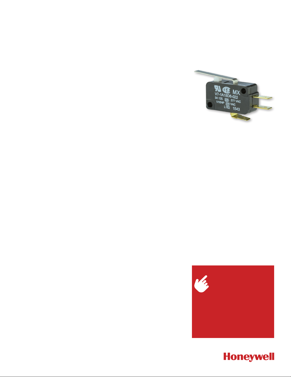
V7 SERIES
MICRO SWITCH Premium Miniature Basic Switches
004987
Issue 4
DESCRIPTION
Honeywell’s MICRO SWITCH V7 Series
premium miniature basic switches
have been designed for long-term
reliability, up to 10 million cycles. These
switches incorporate a snap-spring
mechanism with more than 60 years
of proven service and a high strength
thermoplastic housing for durability.
V7 Series switches are designed with a
standard temperature rating of 85 °C
(185 °F) or options for a temperature
rating up to 175 °C (347 °F).
The switches are available with a single
pole double throw (SPDT) or single pole
single throw (SPST) contact design.
Actuation for the switches includes a
wide range of options, which include the
pin plunger or an assortment of integral
levers with two different lever locations.
Design variations of the internal switch
mechanism and contact materials permit
these switches to reliably control logic
level electrical loads from less than 0.1
A to power duty switching up to 25 A.
Different styles of electrical terminals
solve most installation parameters.
V7 Series miniature basic switches have
been certified by CSA, CE and UL for
global applications as well as being RoHS
compliant. These switches are available
through Honeywell’s worldwide network.
DIFFERENTIATION
• Wide assortment of actuators for the
V7 switch, electrical terminations and
operating characteristics to solve
numerous switch applications
• V7 Series common package size offers
different internal switch designs which
can reliably control a wide range of
electrical loads from logic level to
power duty switching (up to 25 A)
• Honeywell worldwide network for
product availability
VALUE TO CUSTOMERS
• Wide variety of electrical ratings; 0.1 A
up to 25 A
• Available with pin plungers or different
styles of integral levers to integrate
into equipment requirements
• Agency certified for global applications
FEATURES
• High strength thermoplastic housing,
glass-filled PCT high-performance
polyester
• Single pole double throw (SPDT):
3 terminals; single pole single throw
normally closed (SPSTNC)
2 terminals; or single pole single throw
normally open (SPSTNO) 2 terminals
• Wide range of electrical ratings from
logic level (less than 0.1 A) up to 25 A
power duty rated
• Pin plunger actuated or wide
assortment of factory assembled
integral lever options
• Operate force range as low as 15 g
(0.5 oz) up to 400 g (14 oz)
• Rated for up to 10 million cycles
• Temperature range from 40°C to 85°C
[40°F to 185°F] or options for 40°C
to 175°C [40°F to 347°F]
• Common V Series diagonal mounting
pattern; 22,2 mm L x 10,3 mm H [0.88
L x 0.41 in H]
• CSA, ENEC, and UL certifications;
RoHS compliant
POTENTIAL APPLICATIONS
• Vending machines
• Household appliances
• Pressure switch assemblies
• Refrigeration and air-conditioning
equipment*
*An ignition-protected component does not
necessarily comply with all the requirements of the
components for use in hazardous locations as defined
by ANSI/NFPA 70, National Electrical Code.
PORTFOLIO
Honeywell offers a wide range
of MICRO SWITCH basic
switches. These include the
large basic switches,
V Series basic switches, miniature
basic switches, watertight switches
and special duty basic switches.
To view the entire product portfolio,
click here.
Page 2

MICRO SWITCH PREMIUM BASIC SWITCHES, V7 SERIES
TABLE 1. SPECIFICATIONS
CHARACTERISTIC PARAMETER
Circuitry SPDT, SPNO, SPNC
Operating force 0,25 N to 3,9 N [15 g to 397 g]
quick connect; 4,75 mm x 0,51 mm [0.187 in x 0.02 in]
Termination
Actuators pin plunger, integral lever options
Agency certification CSA, ENEC, UL; RoHS compliant
Operating temperature 40°C to 85°C [40°F to 185°F], options for 175°C [347°F]
Mechanical life (cycles) up to 10 million cycles
Contact material silver, gold plated, gold alloy
Housing material glass-filled PCT high-performance polyester
quick connect: 6,35 mm x 0,81 mm [0.25 in x 0.032 in]
PCB (printed circuit board)
TABLE 2. ELECTRICAL RATINGS
RATING CODE UL, CSA ENEC
A
5 A 125 Vac, 250 Vac, 277 Vac
1/10 HP 250 Vac
11 A 1/3 HP 125 Vac, 250 Vac or 277 Vac
B
1/2 A 125 Vdc; 1/4 A 250 Vdc
4 A 125 Vac “L”
1
15.1 A 1/2 HP 125 Vac, 250 Vac or 277 Vac
C
1 /2A 125 Vdc
1/4 A 250 Vdc; 5 A 125 Vac “L”
1
10 A 1/3 HP 125 Vac, 250 Vac or 277 Vac
E
F
S 0.1 A, 125 Vac
V
1/2 A 125 Vdc
1/4 A 250 Vdc, 4 A 125 Vac “L”
1
3 A 125 Vac, 250 Vac, 277 Vac
1/10 HP 250 Vac
4
21 A 1 HP 125 Vac, 250 Vac, 277 Vac
2 HP 250 Vac, 277 Vac
W 15.1 A 125 Vac, 250 Vac, 277 Vac
Z
1
Incandescent lamp rating
2
XX(Y) - XX = max. rated resistive value in amps, and (Y) = max. rated inductive value in amps
3
European ENEC rating requires Mounting Construction code “9” or “0”. See page 4, Mounting Construction column
4
The 0.1A (S Code) design maintains ignition-protected components per UL NCKL2/8 certification for use in refrigeration and air-condi-
25 A, 277 Vac
1 HP, 125 Vac; 2 HP, 250 Vac
3
3 (1) A, 250 Vac
2
10 (3) A, 250 Vac
–
5 (2) A, 250 Vac
2
–
1 (0.05) A, 250 Vac
16 (4) A, 250 Vac
20 (5) A, 250 Vac
2
2
2
2
tioning equipment
2 sensing.honeywell.com
Page 3
MICRO SWITCH PREMIUM BASIC SWITCHES, V7 SERIES
Switch T
,Z
Miniature
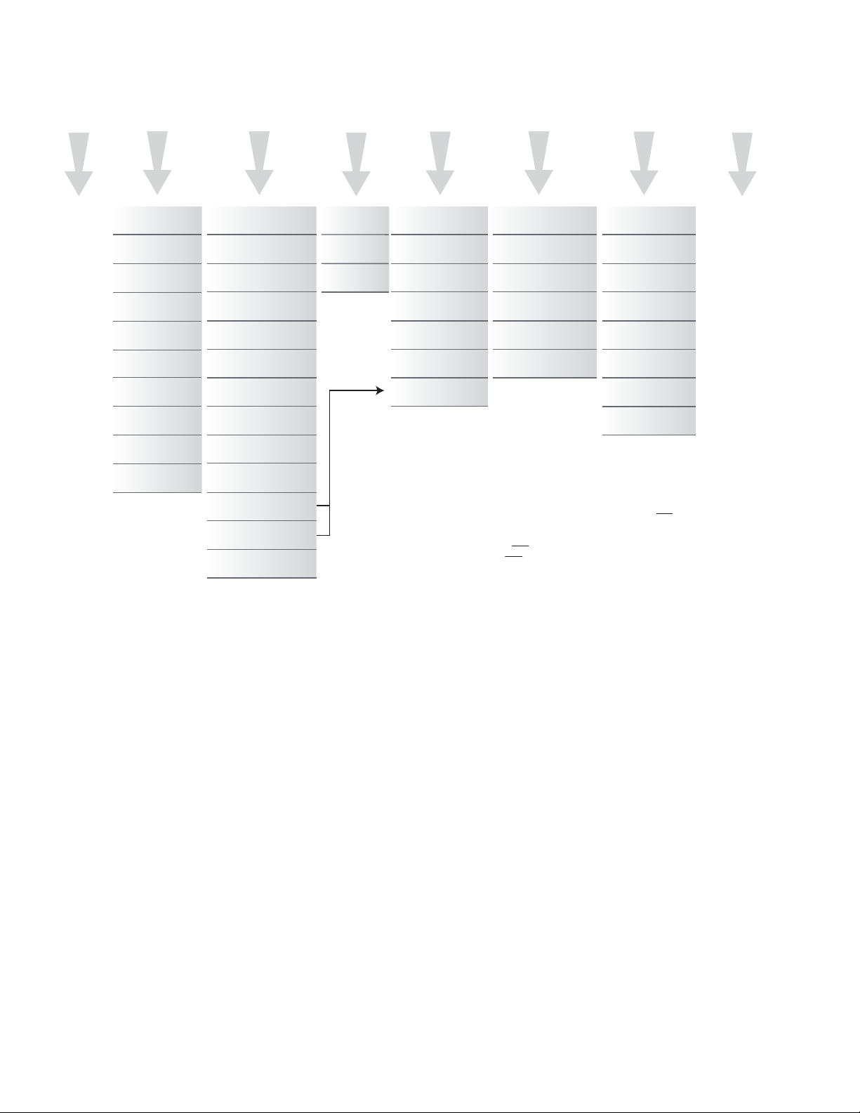
FIGURE 1. PRODUCT NOMENCLATURE
V7
ype
V7 Series
—
A
1
1
1
2
3
4
5
6
7
9
1
Operating
Force
150 g max.
N
175 g max.
P
225 g max.
G
75 g max.
H
50 g max.
I
25 g max.
J
15 g max.
6 oz to 14 oz
max.
8 oz max.
300 g max.
C
Electrical Rating
North
Europe
America
(ENEC)
5 A @
A
125 Vac
11 A @
B
125 Vac
15 A @
K
C
125 Vac
1 A @
D
125 Vac
10 A @
E
125 Vac
3 A @
F
125 Vac
No
H
rating
22 A @
K
125 Vac
0.1 A @
L
S
125 Vac
21 A @
V
125 Vac
15.1 A @
E,M
W
125 Vac
6 A @
E,K
X
125 Vac
25 A @
Z
125 Vac
3 A
10 A
__
1 A
5 A
__
__
20 A
1 A
16 A
__
__
20 A
1
C,F
Circuitry
Code
SPDT
1
SPNO
2
SPNC
3
O
NOTES:
N
A
Not all possible combinations are available, these are only guidelines
L
B
Lever length measured from center of back mounting hole to end of straight lever or center of roller
Y
C
All ratings are UL/CSA, and where noted are also European-rated ENEC
D
Consider the temperature required and the mounting hole size when making this selection
E
Electric ratings “W” and “X” only used with “A” Mounting Construction and vice versa
F
European ENEC rating requires Mounting Construction code “9” or “0”, and Electrical Ratings A,B,D,E,K,S,V
G
Not applicable for Electrical Ratings C,K,V,W,X,Z
H
Not applicable for Electrical Ratings B,C,K,V,W,X,Z
I
Applies to Electrical Ratings A,D,F,S only
J
Applies to Electrical Ratings D,F,S only
K
Applies to 150 g Operate Force and higher
L
Applies to 15 g to 150 g Operate Force
M
Applies to only 300 g Operate Force
N
Applies to only Electrical Rating V
P
Applies to only Electrical Ratings K,Z
7
Mounting/
Construction
150 °C
2,9 mm [0.11 in]
3
mtg. holes
150 °C
3,1 mm [0.12 in]
4
mtg. holes
85 °C
2,9 mm [0.11 in]
7
mtg. holes
85 °C
3,1 mm [0.12 in]
8
mtg. holes
85 °C
F
2,9 mm [0.11 in]
9
mtg. holes
85 °C
F
3,1 mm [0.12 in]
0
mtg. holes
177 °C with
E
2,9 mm [0.11 in]
A
mtg. holes
Termination Style
D,F
D8
E8
D9
E9
P02
P07
Formed quick-connect
terminals available
D8
(Inches)
0.187 x 0.02
quick connect
0.187 x 0.02
quick connect
spread
0.250 x 0.032
quick connect
0.250 x 0.032
quick connect
spread
Left angle
PCB
SPNO on
edge PCB
Lever
Style
Straight
002
22,1 mm [0.87 in]
Straight
022
35,6 mm [1.4 in]
Roller
201
20,6 mm [0.81 in]
Roller
207
34,0 mm [1.34 in]
Sim. roller
263
32,8 mm [1.29 in]
Tall sim. roller
266
34,0 mm [1.34 in]
Straight
048
59,4 mm [2.34 in]
Paddle
636
139,5 mm [5.5 in]
Formed levers available
——
B
Special
Designator
Use only if this switch
has a special feature.
Could be any number.
Sensing and Internet of Things 3
Page 4
MICRO SWITCH PREMIUM BASIC SWITCHES, V7 SERIES
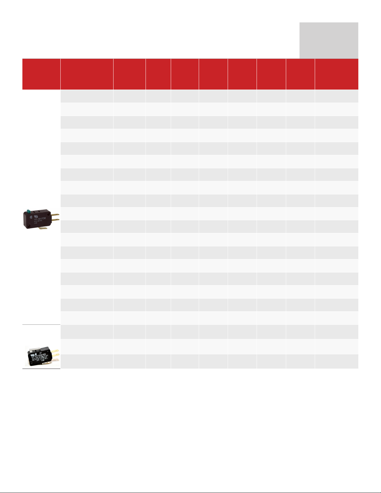
PRODUCT SPECIFICATIONS AND LISTINGS
Contact your Honeywell rep or distributor for additional listings
Pin plunger
BZ/BA Type
Lever
22,1 mm
[0.87 in]
Elect.
Catalog Listing
Rating
UL/CSA
(CE)
V7-2S17DB 0.1 A (---) S SPDT 0,79 [75]
V7-1S17D8 0.1 A (---) S SPDT 1,47 [150]
V7-5F17D8 3 A (---) F SPDT 0,15 [15]
V7-4A17D8 5 A (---) A SPDT 0,25 [25]
V7-3E17D8 10 A (---) E SPDT 0,49 [50]
V7-1B37D8 11 A (---) B SPNC 1,47 [150]
V7-2B17D8 11 A (---) B SPDT 0,74 [75]
V7-2B17E9 11 A (---) B SPDT 0,74 [75]
V7-7B17D8 11 A (---) B SPDT 2,22 [227]
V7-1C17D8 15 A (---) C SPDT 1,47 [150]
V7-1C17E9 15 A (---) C SPDT 1,47 [150]
V7-1C37D8 15 A (---) C SPNC 1,47 [150]
V7-1V19E9 21 A (16 A) V SPDT 1,72 [175]
V7-1V29E9 21 A (16 A) V SPNO 1,72 [175]
V7-1V39E9 21 A (16 A) V SPNC 1,72 [175]
V7-1Z19E9 25 A (20 A) Z SPDT 2,21 [225]
V7-1Z29E9 25 A (20 A) Z SPNO 2,21 [225]
V7-1Z20E9* 25 A (20 A) Z SPNO 2,21 [225]
V7-1C17D8-002 15 A (---) C SPDT 1,57 [160]
V7-1C17E9-002 15 A (---) C SPDT 1,57 [160]
V7-6C18D8-002* 15 A (---) C SPDT 4,05 [413]
Elect.
Rating
Spec.
(page 2)
Contacts
O.F. max.
newtons
[grams]
O. P.
nominal
mm
[inches]
14,7
[0.578]
14,7
[0.578]
14,7
[0.578]
14,7
[0.578]
14,7
[0.578]
14,7
[0.578]
14,7
[0.578]
14,7
[0.578]
14,7
[0.578]
14,7
[0.578]
14,7
[0.578]
14,7
[0.578]
14,7
[0.578]
14,7
[0.578]
14,7
[0.578]
14,7
[0.578]
14,7
[0.578]
14,7
[0.578]
15,2
[0.600]
15,2
[0.600]
15,2
[0.600]
P.T. max.
mm
[inches]
1,19
[0.047]
1,19
[0.047]
1,19
[0.047]
1,19
[0.047]
1,19
[0.047]
1,19
[0.047]
1,19
[0.047]
1,19
[0.047]
1,19
[0.047]
1,19
[0.047]
1,19
[0.047]
1,19
[0.047]
1,19
[0.047]
1,19
[0.047]
1,19
[0.047]
1,19
[0.047]
1,19
[0.047]
1,19
[0.047]
1,52
[0.060]
1,52
[0.060]
1,52
[0.060]
O.F. • Operating force
R.F. • Release force
P.T. • Pretravel
O.T. • Overtravel
D.T. • Differential travel
O.P. • Operating position
O.T. min.
mm
[inches]
1,27
[0.050]
1,27
[0.050]
1,27
[0.050]
1,27
[0.050]
1,27
[0.050]
1,27
[0.050]
1,27
[0.050]
1,27
[0.050]
1,27
[0.050]
1,27
[0.050]
1,27
[0.050]
1,27
[0.050]
1,27
[0.050]
1,27
[0.050]
1,27
[0.050]
1,27
[0.050]
1,27
[0.050]
1,27
[0.050]
0,89
[0.035]
0,89
[0.035]
0,89
[0.035]
mm [inches]
0,05 - 0,25
[0.0020.010]
0,05 - 0,25
[0.0020.010]
0,05 - 0,25
[0.0020.010]
0,05 - 0,25
[0.0020.010]
0,05 - 0,25
[0.0020.010]
0,05 - 0,25
[0.0020.010]
0,05 - 0,25
[0.0020.010]
0,05 - 0,25
[0.0020.010]
0,05 - 0,25
[0.0020.010]
0,05 - 0,25
[0.0020.010]
0,05 - 0,25
[0.0020.010]
0,05 - 0,25
[0.0020.010]
0,05 - 0,25
[0.0020.010]
0,05 - 0,25
[0.0020.010]
0,05 - 0,25
[0.0020.010]
0,05 - 0,25
[0.0020.010]
0,05 - 0,25
[0.0020.010]
0,05 - 0,25
[0.0020.010]
0,36 [0.015]
0,36 [0.015]
0,36 [0.015]
D.T.
max.
max.
max.
4 sensing.honeywell.com
Page 5
MICRO SWITCH PREMIUM BASIC SWITCHES, V7 SERIES
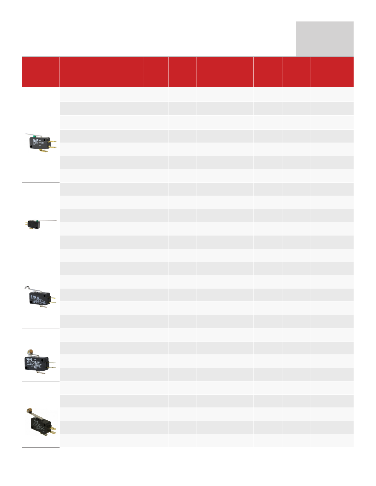
PRODUCT SPECIFICATIONS AND LISTINGS
Contact your Honeywell rep or distributor for additional listings
Lever
35,6 mm
[1.40 in]
Lever
59,4 mm
[2.34 in]
Lever Sim.
Roll 32,8
mm [1.29 in]
Lever, Roller
20,57 mm
[0.81 in]
Lever, Roller
34,04 mm
[1.34 in]
*3,1 mm mtg holes
** 177 °C [350 °F]
Elect.
Catalog Listing
Rating
UL/CSA
(CE)
V7-1S17D8-022 0.1 A (---) S SPDT 0,83 [85]
V7-3S17D8-022 0.1 A (---) S SPDT 0,29 [30]
V7-3S17E9-022 0.1 A (---) S SPDT 0,29 [30]
V7-1B17D8-022 11 A (---) B SPDT 0,80 [82]
V7-1B19D8-022 11 A (10 A) B SPDT 0,80 [82]
V7-2B17D8-022 11 A (---) B SPDT 0,40 [41]
V7-6B19E9-022 11 A (10 A) B SPDT 2,11 [215]
V7-3S17D8-048 0.1 A (---) S SPDT 0,16 [16]
V7-2B17D8-048 11 A (---) B SPDT 0,20 [20]
V7-1C17D8-048 15 A (---) C SPDT 0,44 [45]
V7-1V19E9-048 21 A (16 A) V SPDT 0,54 [55]
V7-9W1AE9-048** 15 A (---) W SPDT 0,88 [90]
V7-1S17D8-263 0.1 A (---) S SPDT 0,88 [90]
V7-3E19E9-263 10 A (5 A) E SPDT 0,32 [33]
V7-1B17D8-263 11 A (---) B SPDT 0,88 [90]
V7-1C17D8-263 15 A (---) C SPDT 0,89 [91]
V7-1V29E9-263 21 A (16 A) V SPNO 1,08 [110]
V7-1Z10E9-263* 25 A (20 A) Z SPDT 1,33 [136]
V7-2S17D8-201 0.1 A (---) S SPDT 0,88 [90]
V7-6B19E9-201 11 A (10 A) B SPDT 4,50 [459]
V7-7B17D8-201 11 A (---) B SPDT 2,78 [283]
V7-1C17D8-201 15 A (---) C SPDT 1,72 [175]
V7-1S17D8-207 0.1 A (---) S SPDT 0,83 [85]
V7-2A17D8-207 5 A (---) A SPDT 0,42 [43]
V7-1B17D8-207 11 A (---) B SPDT 0,83 [85]
V7-1C17D8-207 15 A (---) C SPDT 0,88 [90]
V7-1V19E9-207 21 A (16 A) V SPDT 0,98 [100]
Elect.
Rating
Spec.
(page 2)
Contacts
O.F. max.
newtons
[grams]
O. P.
nominal
mm
[inches]
15,2
[0.60]
15,2
[0.60]
15,2
[0.60]
15,3
[0.603]
15,3
[0.603]
15,3
[0.603]
15,2
[0.60]
15,3
[0.603]
15,3
[0.603]
15,2
[0.603]
15,4
[0.605]
15,2
[0.603]
18,54
[0.730]
18,54
[0.730]
18,54
[0.730]
18,54
[0.730]
18,49
[0.728]
18,49
[0.728]
20,57
[0.810]
20,52
[0.808]
20,52
[0.808]
20,57
[0.810]
20,57
[0.810]
20,57
[0.810]
20,57
[0.810]
20,57
[0.810]
20,52
[0.808]
O.F. • Operating force
R.F. • Release force
P.T. • Pretravel
O.T. • Overtravel
D.T. • Differential travel
O.P. • Operating position
P.T. max.
mm
[inches]
3,04
[0.120]
3,04
[0.120]
3,04
[0.120]
3,04
[0.120]
3,25
[0.128]
3,04
[0.120]
3,25
[0.128]
5,97
[0.235]
5,97
[0.235]
5,94
[0.234]
6,35
[0.250]
6,35
[0.250]
2,79
[0.110]
2,54
[0.100]
2,79
[0.110]
2,79
[0.110]
2,90
[0.114]
2,90
[0.114]
1,19
[0.047]
1,42
[0.056]
1,42
[0.056]
1,19
[0.047]
2,84
[0.112]
2,92
[0.115]
2,92
[0.115]
2,92
[0.115]
3,07
[0.121]
O.T. min.
mm
[inches]
2,16
[0.085]
2,16
[0.085]
2,16
[0.085]
1,70
[0.067]
1,78
[0.070]
1,70
[0.067]
1,35
[0.053]
3,00
[0.118]
2,92
[0.115]
4,19
[0.165]
3,05
[0.120]
3,15
[0.124]
1,90
[0.075]
1,90
[0.075]
1,52
[0.060]
1,55
[0.061]
1,62
[0.064]
1,62
[0.064]
1,02
[0.040]
0,86
[0.034]
0,86
[0.034]
0,81
[0.032]
2,03
[0.080]
1,52
[0.060]
1,52
[0.060]
1,52
[0.060]
1,65
[0.065]
D.T.
mm [inches]
0,76 [0.030]
max.
0,76 [0.030]
max.
0,76 [0.030]
max.
0,69 [0.027]
max.
0,71 [0.028]
max.
0,71 [0.027]
max.
0,76 [0.030]
max.
1,27 [0.050]
max.
1,27 [0.050]
max.
1,52 [0.060]
max.
1,40 [0.055]
max.
1,37 [0.054]
max.
0,76 [0.030]
max.
0,76 [0.030]
max.
0,76 [0.030]
max.
0,61 [0.024]
max.
0,64 [0.025]
max.
0,64 [0.025]
max.
0,38 [0.015]
max.
0,33 [0.013]
max.
0,33 [0.013]
max.
0.30 [0.012]
max.
0,76 [0.030]
max.
0,64[0.025] max.
0,76 [0.030]
max.
0,64[0.025] max.
0,76 [0.030]
max.
Sensing and Internet of Things 5
Page 6
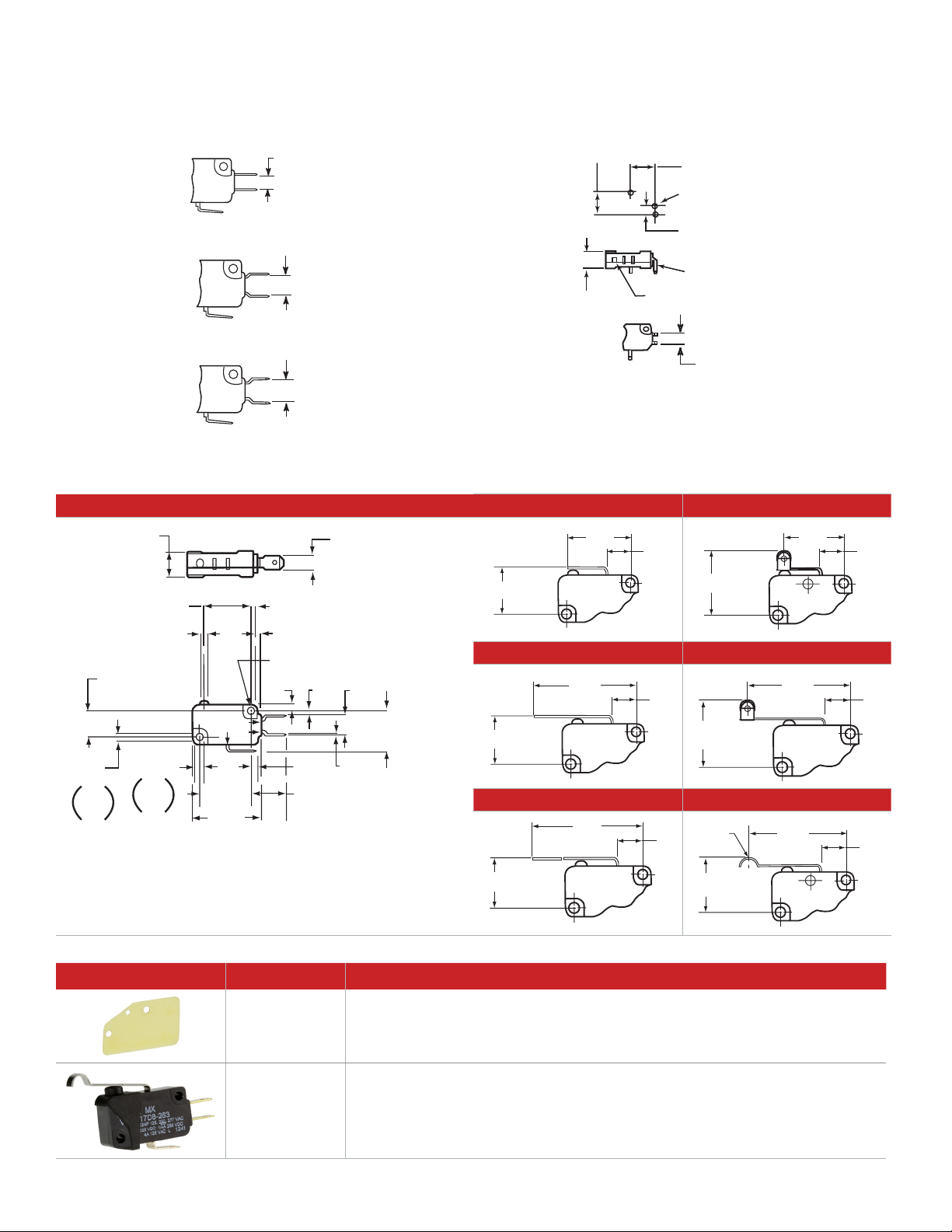
MICRO SWITCH PREMIUM BASIC SWITCHES, V7 SERIES
10,2
[0.40]
6,4
[0.25]
COM
NC
NO
2,8
[0.11]
1,5
[0.06]
8,9
[0.35]
0,8
[0.03]
2,4
[0.10]
14,4 [0.57]
22,2
[0.88]
28,8
[1.14]
3,20
[0.126]
3,46
[0.134]
opt
18,2
[0.72]
(3)
dia
3,10
[0.122]
opt
2,90
[0.114]
10,3
[0.41]
dia
20,2 [0.80]
2,8 [0.11]
1,0 [0.04]
2,90 [0.114] Ø hole (3,10/0.122 option)
max.
2,8 [0.11]
8,2
[0.32]
22,1
[0.87]
15,2
[0.60]
Operating
position
8,2
[0.32]
20,6
[0.81]
Operating
position
20,6
[0.81]
8,2
[0.32]
35,6
[1.40]
15,2
[0.60]
Operating
position
8,2
[0.32]
34,0
[1.34]
20,6
[0.81]
Operating
position
8,2
[0.32]
59,4
[2.34]
15,2
[0.60]
Operating
position
8,2
[0.32]
32,8
[1.29]
18,5
[0.73]
Operating
position
3,0
[0.12]
R
D8
5,48
[0.216]
E8
8,28
[0.326]
E9
7,67
[0.302]
15,24
[0.600] ref.
15,24
[0.600] ref.
10,16
[0.400]
6,4
[0.25]
Ø 1,78
[Ø 0.070] ref. (3)
5,08
[0.200] ref.
0,81 x 1,57
[0.32 x 0.062] pin (3)
Plastic plunger
AVAILABLE TERMINALS
Quick Connect (QC)
D8 Terminals: 0.187 in wide x 0.020 in thick.
E8 Terminals: 0.187 in wide x 0.020 in thick.
E9 Terminals: 0.250 in wide x 0.032 in thick.
STANDARD ACTUATOR OPTIONS
Printed Circuit Board (PO2)
These terminals interface with snap-on receptacles and other
components from AMPMODU interconnection system.
Straight Lever (-002) Roller Lever (-201)
Straight lever (-022)
ACCESSORIES
6 sensing.honeywell.com
Straight Lever (-022) Roller Lever (-207)
Straight Lever (-048) Simulated Roller Lever (-263)
Part Number Description
15PA177V7 Insulator packet: 500 pieces of 0,46 mm [0.018 in] thick varnished fiberglass
15PA260 Elastomer plunger boot seal: dust and splash resistant (Switch not included)
Page 7

WARRANTY/REMEDY
Honeywell warrants goods of its manufacture as being free of defective materials and faulty workmanship during the
applicable warranty period. Honeywell’s
standard product warranty applies unless agreed to otherwise by Honeywell in
writing; please refer to your order acknowledgment or consult your local sales
office for specific warranty details. If warranted goods are returned to Honeywell
during the period of coverage, Honeywell
will repair or replace, at its option, without
charge those items that Honeywell,
in its sole discretion, finds defective.
The foregoing is buyer’s sole remedy
and is in lieu of all other warranties,
expressed or implied, including those
of merchantability and fitness for a
particular purpose. In no event shall
Honeywell be liable for consequential,
special, or indirect damages.
While Honeywell may provide application assistance personally, through our
literature and the Honeywell web site, it
is buyer’s sole responsibility to determine
the suitability of the product in the application.
m WARNING
PERSONAL INJURY
DO NOT USE these products as safety
or emergency stop devices or in any
other application where failure of the
product could result in personal injury.
Failure to comply with these
instructions could result in death or
serious injury.
m WARNING
MISUSE OF
DOCUMENTATION
• The information presented in this
product sheet is for reference only.
Do not use this document as a
product installation guide.
• Complete installation, operation,
and maintenance information
is provided in the instructions
supplied with each product.
Failure to comply with these
instructions could result in death or
serious injury.
FOR MORE INFORMATION
Honeywell Sensing and Internet of
Things services its customers through a
worldwide network of sales offices and
distributors. For application assistance,
current specifications, pricing or the
nearest Authorized Distributor, visit
sensing.honeywell.com or call:
International +815 618 3231
USA/Canada +302 613 44915
Honeywell
Sensing and Internet of Things
9680 Old Bailes Road
Fort Mill, SC 29707
honeywell.com
Specifications may change without
notice. The information we supply is
believed to be accurate and reliable as of
this writing. However, Honeywell assumes
no responsibility for its use.
0049874EN | 4 | 12/19
© 2019 Honeywell International Inc. All rights reserved.
 Loading...